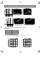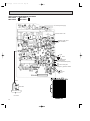
1
OB207t-1qxp
25/9/97 8:51 PM
Page 1
This Servise Manual OB207 deals with MSH-07/09/12/18/24NV-E1,
MUH-07/09/12/18/24NV-E1, MSH-18NV-E2, and MUH-18NV-E2 in
OB176 REVISED EDITION-A issued in July in1997.
Therefore, please refer to OB207, not to OB176 REVISED
EDITION-A, for the above models.
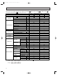
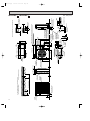
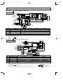
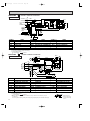
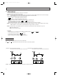
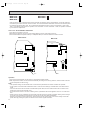
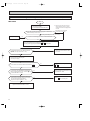
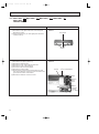
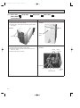
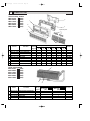
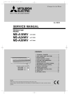
SPLIT-TYPE,HEAT PUMP AIR CONDITIONERS
No. OB207
SERVICE MANUAL
Wireless type
Models
MSH-07NV
MSH-09NV
MSH-12NV
MSH-18NV
MSH-24NV
MSH-07NV
MSH-09NV
MSH-12NV
MSH-18NV
MSH-24NV
MSH-18NV
-
E1 (WH)
E1 (WH)
E1 (WH)
E1 (WH)
E1 (WH)
E2 (WH)
E2 (WH)
E2 (WH)
E2 (WH)
E2 (WH)
E3 (WH)
·
·
·
·
·
·
·
·
·
·
·
MUH-07NV
MUH-09NV
MUH-12NV
MUH-18NV
MUH-24NV
MUH-07NV
MUH-09NV
MUH-12NV
MUH-18NV
MUH-24NV
MUH-18NV
-
E1
E1
E1
E1
E1
E2
E2
E2
E2
E2
E3
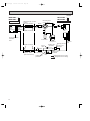
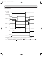
CONTENTS
MSH-18NV MSH-18NV MSH-18NV -
E1
E2
E3
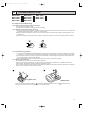
1. TECHNICAL CHANGES ····································2
2. PART NAMES AND FUNCTIONS······················3
3. SPECIFICATION·················································6
4. OUTLINES AND DIMENSIONS ······················ 11
5. WIRING DIAGRAM ··········································15
6. REFRIGERANT SYSTEM DIAGRAM ··············24
7. PERFORMANCE CURVES ······························29
8. MICROPROCESSOR CONTROL ····················33
9. SERVICE FUNCTIONS ····································44
10. TROUBLESHOOTING······································47
11. DISASSEMBLY INSTRUCTIONS·····················60
12. PARTS LIST······················································70
13. OPTIONAL PARTS ····································BACK
Refer to the Service Manual OB185 when MSH-07/09/12NV- E1 , MSH-07/09/12/18NV- E2 , and MSH-18NV- E3
are connected with MXZ-32NV- E1 as multi system units.
OB207t-1qxp
1
25/9/97 8:51 PM
Page 2
TECHNICAL CHANGES
MSH-17NV - E1 ➔MSH-07NV - E2
1. Indoor electronic control P.C.board has changed.
However, it is compatible between E1 and E2 models.
2. Auto restart function is added.
MSH-09NV - E1 ➔MSH-09NV - E2
1. Indoor electronic control P.C.board has changed.
However, it is compatible between E1 and E2 models.
2. Auto restart function is added.
MSH-12NV - E1 ➔MSH-12NV - E2
1. Indoor electronic control P.C.board has changed.
However, it is compatible between E1 and E2 models.
2. Auto restart function is added.
MSH-18NV - E2 ➔MSH-18NV - E3
1. Indoor electronic control P.C.board has changed.
However, it is compatible between E2 and E3 models.
2. Auto restart function is added.
MSH-24NV - E1 ➔MSH-24NV - E2
1. Indoor electronic control P.C.board has changed.
However, it is compatible between E1 and E2 models.
2. Auto restart function is added.
2
OB207t-1qxp
25/9/97 8:51 PM
2
Page 3
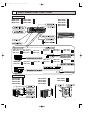
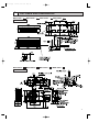
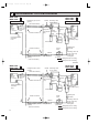
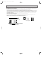
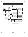
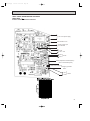
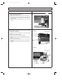
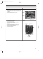
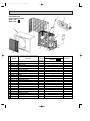
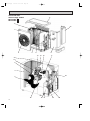
PART NAMES AND FUNCTIONS
INDOOR UNIT
MSH-07NV - E2
MSH-09NV - E2
MSH-12NV - E2
MSH-18NV
MSH-24NV
MSH-18NV
MSH-24NV
MSH-18NV
MSH-07NV - E1
MSH-09NV - E1
MSH-12NV - E1
(When the front panel is open)
MSH-07NV - E1 MSH-09NV - E1
MSH-07NV - E2 MSH-09NV - E2
MSH-18NV - E1
MSH-24NV - E2
MSH-24NV - E1
MSH-18NV - E3
MSH-12NV - E1
MSH-12NV - E2
MSH-18NV - E2
- E1
- E1
- E2
- E2
- E3
MSH-07NV - E1
MSH-07NV - E2
MSH-09NV - E1
MSH-09NV - E2
MSH-12NV - E1
MSH-12NV - E2
MSH-18NV - E1
MSH-24NV - E2
MSH-24NV - E1
MSH-18NV - E3
MSH-18NV - E2
OUTDOOR UNIT
MUH-07NV
MUH-09NV
MUH-07NV
MUH-09NV
- E1
- E1
- E2
- E2
MUH-12NV
MUH-18NV
MUH-18NV
MUH-18NV
-
E1
E1
MUH-24NV MUH-24NV -
E1
E2
E2
E3
3
OB207t-1qxp
25/9/97 8:51 PM
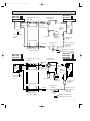
MSH-07NV - E1
Page 4
MSH-09NV - E1
REMOTE CONTROLLER
4
MSH-12NV - E1
MSH-18NV - E1
MSH-18NV - E2
OB207t-1qxp
25/9/97 8:51 PM
MSH-07NV
MSH-12NV
MSH-07NV
MSH-12NV
MSH-24NV
Page 5
- E1 (Serial number 7000201T~) MSH-09NV - E1 (Serial number 7000201T~)
- E1 (Serial number 7000001T~) MSH-24NV - E1
- E2
MSH-09NV - E2
- E2
MSH-18NV - E2 (Serial number 7000001T~)
- E2
MSH-18NV - E3
5
OB207t-1qxp
3
25/9/97 8:51 PM
Page 6
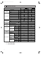
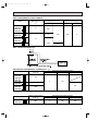
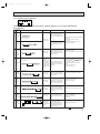
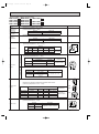
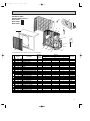
SPECIFICATION
Model
MSH-07NV -
Dehumidification
K /h INDOOR 492 OUTDOOR 1620 INDOOR 492 OUTDOOR 1620
Air flow
Power outlet
A
Running current
A
3.30-3.20
3.15-3.05
4.10-4.00
4.30-4.10
W
710-750
680-720
880-920
920-940
A(kW)
—
—
—
—
98-96
97-96
Power input
Auxiliary heater
Electrical data
%
98-98
Starting current
A
25
Compressor motor current
A
Fan motor current
A
Indoor
Outdoor
fan motor
3.80-3.60
3.60-3.50
RH-174VGHT
W
650
800
"
C-R4.17 C-S5.75
C-R3.26 C-S5.82
RC4V19-AA
RC4V19-AA
Model
Winding resistance(at20:)
"
Model
Winding resistance(at20:)
Outdoor unit
"
WHT-BLK292 BLK-RED324 WHT-BLK292 BLK-RED324
RA6V29-CB
RA6V29-CB
WHT-BLK218.0 BLK-RED423.7 WHT-BLK218.0 BLK-RED423.7
Width
mm
815
815
Height
mm
275
275
Depth
mm
183
183
Width
mm
780
780
Height
mm
540
540
Depth
mm
255
255
Indoor unit
kg
8
8
Outdoor unit
kg
34
34
5
5
37
37
Air direction
Indoor unit
dB
(Hi)
Outdoor unit
dB
47
48
Fan speed
Indoor unit
rpm
1,100
1,100
(Hi)
Outdoor unit
rpm
790-820
790-820
Fan speed
Indoor unit
4
4
regulator
Outdoor unit
Sound level
1
1
Refrigerant filling capacity(R-22)
kg
0.85
0.85
Thermistor
NOTE:Test conditions
Cooling : Indoor
Outdoor
Heating : Indoor
Outdoor
6
2.65-2.55
2.80-2.70
INDOOR 0.17 OUTDOOR 0.33 INDOOR 0.17 OUTDOOR 0.33
3.37-3.30
2.84-2.72
3.68-3.47
3.10-2.93
Winding resistance(at20:)
Indoor unit
Special remarks
25
Output
Dimensions
Weight
10
RH-135VGHT
Model
fan motor
10
Power factor
Coefficient of performance(C.O.P)
Compressor
MSH-09NV - E1 E2
Heating
Cooling
Single phase,220-240V,50Hz Single phase,220-240V,50Hz
3.1
2.5
2.5
2.2
kW
—
1.1
—
0.8
R/h
Capacity
Capacity
E2
Heating
Cooling
Function
Power supply
E1
RT11(at25:)
k"
10
10
RT12(at25:)
k"
10
10
RT61(at0:)
k"
33.18
33.18
DB27°C / WB19°C
DB35°C / WB24°C
DB20°C /WB15.5°C
DB 7°C / WB 6°C
OB207t-1qxp
25/9/97 8:51 PM
Page 7
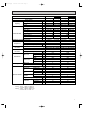
Model
MSH-12NV -
Power supply
kW
Capacity
R/h
Dehumidification
fan motor
—
2.5
5.95-6.10
9.4-9.2
9.2-9.0
10
15
W
1220-1300
1260-1350
2030-2120
1980-2070
A(kW)
—
—
—
—
Power factor
%
96-92
96-92
98-96
98-96
Starting current
A
Compressor motor current
A
Fan motor current
A
35
5.41-5.56
5.21-5.36
52-58
8.56-8.36
8.76-8.56
INDOOR 0.17 OUTDOOR 0.37 INDOOR 0.25 OUTDOOR 0.39
2.73-2.61
2.51-2.41
3.17-2.96
2.78-2.61
RH-231VHAT
NH-36VMDT
Output
W
1100
1700
Winding resistance(at20:)
"
C-R2.1 C-S3.9
C-R1.2 C-S2.7
RC4V19-AA
RA4V27-EA
Model
Winding resistance(at20:)
Winding resistance(at20:)
Outdoor unit
"
Model
Dimensions
"
WHT-BLK292 BLK-RED324 WHT-BLK183.8 BLK-RED250.5
RA6V40-EC or EE
RA6V50-OD or OF
WHT-BLK130 BLK-RED134.6 WHT-BLK116.4 BLK-RED111.0
Width
mm
815
1015
Height
mm
275
320
Depth
mm
183
190
Width
mm
850
850
Height
mm
605
605
Depth
mm
290
290
Indoor unit
kg
8
14
Outdoor unit
kg
43
59
5
5
dB
42
42
Air direction
Special remarks
—
1.6
5.75-5.90
Indoor unit
Weight
Single phase,220-240V,50Hz Single phase,220-240V,50Hz
5.4
5.1
4.0
3.4
A
Model
Outdoor
E3
Heating
A
Coefficient of performance(C.O.P)
fan motor
E2
Running current
Auxiliary heater
Indoor
E1
Power outlet
Power input
Compressor
MSH-18NV Cooling
K /h INDOOR 558 OUTDOOR 2130-2244 INDOOR 756 OUTDOOR 2142
Air flow
Electrical data
E2
Heating
Cooling
Function
Capacity
E1
Sound level
Indoor unit
(Hi)
Outdoor unit
dB
50
52
Fan speed
Indoor unit
rpm
1230
1180
(Hi)
Outdoor unit
rpm
780-820
810-845
4
4
Fan speed
Indoor unit
regulator
Outdoor unit
1
1
Refrigerant filling capacity(R-22)
kg
1.15
1.8
RT11(at25:)
k"
10
10
RT12(at25:)
k"
10
10
RT61(at0:)
k"
33.18
33.18
Thermistor
NOTE:Test conditions
Cooling : Indoor
Outdoor
Heating : Indoor
Outdoor
DB27°C / WB19°C
DB35°C / WB24°C
DB20°C /WB15°.5C
DB 7°C / WB 6°C
7
OB207t-1qxp
25/9/97 8:51 PM
Page 8
Model
MSH-24NV -
Function
Capacity
kW
6.0
6.2
Dehumidification
R/h
3.1
—
Power outlet
K /h
816
A
25
Running current
A
12.6-11.7
Power input
W
2720-2750
Power factor
%
98
Starting current
A
59
Compressor motor current
A
Fan motor current
A
Outdoor
fan motor
Output
W
Winding resistance(at20:)
"
Winding resistance(at20:)
2200
C-R 0.96
C-S 2.07
"
WHT-BLK183.8 BLK-RED250.5
RA6V85-AA
"
WHT-BLK62.7 BLK-YLW30.2 YLW-RED62.9
Width
mm
1015
Height
mm
320
Depth
mm
190
Width
mm
870
Height
mm
850
Depth
Model
Winding resistance(at20:)
Outdoor unit
mm
295
Indoor unit
kg
14
Outdoor unit
kg
72
5
Air direction
Indoor unit
dB
45
(Hi)
Outdoor unit
dB
53
Fan speed
Indoor unit
rpm
1,260
(Hi)
Outdoor unit
rpm
720-750
Fan speed
Indoor unit
regulator
Outdoor unit
Sound level
4
2
Refrigerant filling capacity(R-22)
kg
2.4
Thermistor
NOTE:Test conditions
Cooling : Indoor
Outdoor
Heating : Indoor
Outdoor
8
2.51-2.40
RA4V27-EC
Model
Dimensions
Special remarks
10.63-10.13
NH-47VMDT
Indoor unit
Weight
11.73-10.83
INDOOR 0.29 OUTDOOR 0.58
2.21-2.18
Model
Indoor
2470-2580
—
Coefficient of performance(C.O.P)
fan motor
11.5-11.0
A(kW)
Auxiliary heater
Compressor
Heating
Single phase,220-240V,50Hz
Air flow
Electrical data
E2
Cooling
Power supply
Capacity
E1
RT11(at25:)
k"
10
RT12(at25:)
k"
10
RT61(at0:)
k"
33.18
DB27°C / WB19°C
DB35°C / WB24°C
DB20°C /WB15.5°C
DB 7°C / WB 6°C
OB207t-1qxp
25/9/97 8:51 PM
Page 9
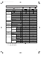
Refer to the Service Manual OB185 when MSH-07/09/12NVconnected with MXZ-32NV- E1 as multi system units.
Model
Dehumidification
kW
—
R/h
—
K /h
Air flow
—
—
—
—
492
10
W
35
35
A(kW)
—
—
Power factor
%
94-86
94-86
Starting current
A
—
—
Compressor motor current
A
—
—
Fan motor current
A
0.17
0.17
—
—
—
—
—
—
Output
W
Winding resistance(at20:)
"
Model
Winding resistance(at20:)
"
Model
—
—
RC4V19-AA
RC4V19-AA
WHT-BLK292 BLK-RED324 WHT-BLK292 BLK-RED324
—
—
"
—
—
Width
mm
815
815
Height
mm
275
275
Depth
mm
183
183
Width
mm
—
—
Height
mm
—
—
Depth
mm
—
—
Winding resistance(at20:)
Indoor unit
kg
8
8
Outdoor unit
kg
—
—
5
5
dB
37
37
Air direction
Special remarks
—
0.17
Outdoor unit
Weight
492
—
10
Dimensions
Sound level
Indoor unit
(Hi)
Outdoor unit
dB
—
—
Fan speed
Indoor unit
rpm
1,100
1,100
(Hi)
Outdoor unit
rpm
—
—
4
4
Fan speed
Indoor unit
regulator
Outdoor unit
—
—
Refrigerant filling capacity(R-22)
kg
—
—
RT11(at25:)
k"
10
10
RT12(at25:)
k"
10
10
RT61(at0:)
k"
—
—
Thermistor
NOTE:Test conditions
Cooling : Indoor
Outdoor
Heating : Indoor
Outdoor
are
Heating
0.17
Indoor unit
E3
(INDOOR UNIT)
Cooling
A
Model
fan motor
Heating
E1 E2
A
Coefficient of performance(C.O.P)
Outdoor
(INDOOR UNIT) MSH-09NV-
Running current
Auxiliary heater
fan motor
, and MSH-18NV-
Power outlet
Power input
Indoor
E2
Single phase,220-240V,50Hz Single phase,220-240V,50Hz
Capacity
Compressor
E1 E2
Cooling
Power supply
Electrical data
, MSH-07/09/12/18NV-
MSH-07NV-
Function
Capacity
E1
Please refer to Service manual OB185 for capacity.
DB27°C / WB19°C
DB35°C / WB24°C
DB20°C /WB15.5°C
DB 7°C / WB 6°C
9
OB207t-1qxp
25/9/97 8:51 PM
Page 10
Refer to the Service Manual OB185 when MSH-07/09/12NVconnected with MXZ-32NV- E1 as multi system units.
Model
Function
Cooling
fan motor
K /h
558
756
—
—
10
10
Running current
A
0.17
0.28
W
35
60
A(kW)
—
—
Power factor
%
94-86
97-89
Starting current
A
—
—
Compressor motor current
A
—
—
Fan motor current
A
0.17
0.25
—
—
—
—
Output
W
—
—
Winding resistance(at20:)
"
—
—
RA4V19-AA
RA4V27-EA
Model
Winding resistance(at20:)
"
Model
WHT-BLK292 BLK-RED324 WHT-BLK184 BLK-RED251
—
—
"
—
—
Width
mm
815
1015
Height
mm
275
320
Depth
mm
183
190
Width
mm
—
—
Height
mm
—
—
Depth
Winding resistance(at20:)
mm
—
—
Indoor unit
kg
8
14
Outdoor unit
kg
—
—
5
5
Indoor unit
dB
42
42
(Hi)
Outdoor unit
dB
—
—
Fan speed
Indoor unit
rpm
1,230
1,180
(Hi)
Outdoor unit
rpm
—
—
Fan speed
Indoor unit
4
4
regulator
Outdoor unit
Sound level
—
—
Refrigerant filling capacity(R-22)
kg
—
—
RT11(at25:)
k"
10
10
RT12(at25:)
k"
10
10
RT61(at0:)
k"
—
—
Thermistor
NOTE:Test conditions
Cooling : Indoor
Outdoor
Heating : Indoor
Outdoor
10
—
Power outlet
Air direction
Special remarks
—
A
Outdoor unit
are
Heating
—
Dimensions
Weight
Cooling
—
Indoor unit
E3
(INDOOR UNIT)
kW
Model
Outdoor
Heating
E2 E3
R/h
Coefficient of performance(C.O.P)
Indoor
UNIT) MSH-18NV-
Dehumidification
Auxiliary heater
fan motor
, and MSH-18NV-
Capacity
Power input
Compressor
E1 E2 (INDOOR
E2
Single phase,220-240V,50Hz Single phase,220-240V,50Hz
Air flow
Electrical data
, MSH-07/09/12/18NV-
MSH-12NV-
Power supply
Capacity
E1
Please refer to Service manual OB185 for capacity.
DB27°C / WB19°C
DB35°C / WB24°C
DB20°C /WB15.5°C
DB 7°C / WB 6°C
OB207t-1qxp
25/9/97 8:51 PM
4
Page 11
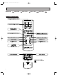
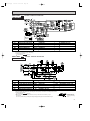
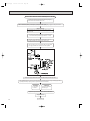
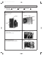
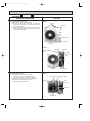
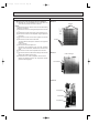
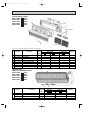
OUTLINES AND DIMENSIONS
Unit: mm
MSH-07NV - E1
MSH-09NV - E1
MSH-07NV - E2
MSH-09NV - E2
INDOOR UNIT
MUH-07NV - E1
MUH-09NV - E1
MUH-07NV - E2
MUH-09NV - E2
OUTDOOR UNIT
11
OB207t-1qxp
25/9/97 8:51 PM
Page 12
Unit: mm
MSH-12NV - E1
MSH-12NV - E2
INDOOR UNIT
9.52
ides
left s only
/
t
h
r rig p has
nt o
.
o
e fro nt, the t tructed
h
t
f
s
I
a
b
c
o
a
n
v
are 10cm u
e
to b
MUH-12NV - E1 MUH-12NV - E2
OUTDOOR UNIT
If the right/left sides or
back side is vacant,the
front has only to be 50cm
unobstructed.
12
OB207t-1qxp
25/9/97 8:51 PM
Page 13
Unit: mm
MSH-24NV - E1
MSH-18NV - E2
MSH-24NV - E2
4holes 11
11✕20
Indoor unit
648
217
254
60
40
20
150
995
MSH-18NV - E3
450
3
450
297
MSH-18NV - E1
INDOOR UNIT
438
352
Wall hole [75
Installation plate
1015
190
5
320
Installation plate
{
Air in
50
775
17.5
Air out
Drain hose [16
Insulation [28
Power supply cord
Lead to right 2m
Lead to left 1m
160
56
190
Liquid line [8-0.5m
Gas line [12-0.43m
Insulation [50 O.D
[28
[
28 I.D
MUH-18NV - E1
MUH-18NV - E2
es
ft sid
ht/le s only
g
i
r
a
r
nt o e top h ted.
h
c
e fro
If th acant, t nobstru
v
are 10cm u
e
to b
MUH-18NV - E3
OUTDOOR UNIT
If the right/left sides or
back side is vacant,the
front has only to be 50cm
unobstructed.
13
95
For 10 units or less
Rear piping hole
10
138
200
Rear fresh
air intake
23
Side air intake
7
295(11-5/8)
Outlet guide
installation hole
Handle for moving
24(1)
33
1000
524
Drain hole
441
Handle
for moving
100
40
524
870(34-1/4)
Drain hole
2-12✕23 Oval holes
(standard bolt M10)
302
Air outlet
Service panel
10
Note:Allow adequate
upper clearance
10
500
Front opening
0
12
R6
Service space
65
120
60
Knock out holes for
power line 2-[27
Standard bolt length
MUH-24NV- E2
Front right piping holesdetail figures
Knock out hole
for right piping
(refrigerant,drainage
R2
and wiring)
Knock out hole
for front piping
(refrigerant,drainage
and wiring)
Bottom
piping hole
33
60
Refrigerant-pipe flared
connection [15.88 5/8F
Refrigerant-pipe flared
connection [9.52 3/8F
Ground
terminal
Handle for moving
Terminal block for power line
2-U-shaped
notched
holes
104
10
Terminal block for indoor and outdoor unit connection
337
Air intake
553
45
Air intake
185
(7-9/32)
352
42
850(33-7/16)
500(19-11/16)
17
185
(7-9/32)
0
179
500
80
Outdoor Unit-Necessary surrounding clearance
(Concentrated installation)
The upper side must be open.
403
150
17
39.5 27.5
330(13)
362(14-1/4)
15
200
Outdoor Unit-Necessary surrounding clearance
R2
45
MUH-24NV- E1
53
14
25/9/97 8:52 PM
25 max.
OB207t-1qxp
Page 14
Unit : mm (inch)
OB207t-1qxp
25/9/97 8:52 PM
5
Page 15
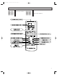
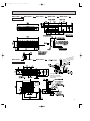
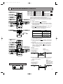
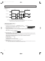
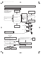
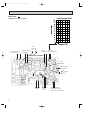
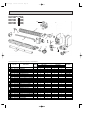
WIRING DIAGRAM
MODELS WIRING DIAGRAM
MSH-07NV - E1
MSH-09NV - E1
INDOOR UNIT
❈
❈
~
❈
❈
❈
❈
~/N
FOR MULTI SYSTEM
TO OUTDOOR 12VDC
UNIT
CONNECTING
L
3
2
N
;
NAME
SYMBOL
SYMBOL
NAME
SYMBOL
NAME
C11
INDOOR FAN CAPACITOR
NR11
VARISTOR
TB
TERMINAL BLOCK
F12
FUSE(93:)
RT11
ROOM TEMPERATURE THERMISTOR
MV
VANE MOTOR
F11
FUSE(3.15A)
RT12
INDOOR COIL THERMISTOR
SR11
MF
INDOOR FAN MOTOR
52C
SOLID STATE RELAY
CONTACTOR
NOTE:1. For the outdoor electric wiring refer to the outdoor unit electric wiring diagram for servicing.
2. Use copper conductors only.(For field wiring)
3. Symbols below indicate.
: Terminal block,
: Connector
MUH-07NV - E1
MUH-09NV - E1
MODELS WIRING DIAGRAM
OUTDOOR UNIT
❈
❈
❈
❈
❈
❈
SYMBOL
NAME
SYMBOL
NAME
❈
SYMBOL
NAME
C1
COMPRESSOR CAPACITOR
MF
OUTDOOR FAN MOTOR
X62
REVERSING VALVE COIL RELAY
C65
OUTDOOR FAN MOTOR CAPACITOR
NR61
VARISTOR
21S4
REVERSING VALVE COIL
52C
CONTACTOR
RT61
DEFROST THERMISTOR
IC881
DC/DC CONVERTER
F61
FUSE(2A)
SR61
SOLID STATE RELAY
MC
COMPRESSOR(INNER THERMOSTAT)
TB
TERMINAL BLOCK
NOTE:1. Use copper conductors only.(For field wiring)
2. Since the indoor and outdoor unit connecting wires have polarity, connect them according to the numbers.
3. Symbols below indicate.
: Terminal block,
: Connector
4. “❈”show the terminals with a lock mechanism, so they cannot be removed when you pull
the lead wire.
Be sure to pull the wire by pushing the locking lever(projected part) of the terminal with a finger.
1.Slide the sleeve.
2.Pull the wire while
pushing the locking
lever.
15
OB207t-1qxp
25/9/97 8:52 PM
Page 16
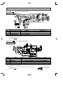
MODEL WIRING DIAGRAM
MSH-12NV - E1
INDOOR UNIT
❈
❈
~
❈
❈
❈
❈
~/N
FOR MULTI SYSTEM
TO OUTDOOR 12VDC
UNIT
CONNECTING
L
3
2
N
;
NAME
SYMBOL
NAME
SYMBOL
NR11
VARISTOR
FUSE(93:)
RT11
FUSE(3.15A)
RT12
C11
INDOOR FAN CAPACITOR
F12
F11
MF
INDOOR FAN MOTOR
SYMBOL
NAME
TB
TERMINAL BLOCK
ROOM TEMPERATURE THERMISTOR
MV
VANE MOTOR
INDOOR COIL THERMISTOR
SR11
SOLID STATE RELAY
CONTACTOR
52C
NOTE:1. For the outdoor electric wiring refer to the outdoor unit electric wiring diagram for servicing.
2. Use copper conductors only.(For field wiring)
3. Symbols below indicate.
: Terminal block,
: Connector
MODEL WIRING DIAGRAM
MUH-12NV - E1
OUTDOOR UNIT
❈
❈
❈
❈
❈
❈
SYMBOL
NAME
SYMBOL
C1
COMPRESSOR CAPACITOR
MF
C65
OUTDOOR FAN MOTOR CAPACITOR
NR61
52C
CONTACTOR
RT61
F61
FUSE(2A)
SR61
SOLID STATE RELAY
MC
COMPRESSOR(INNER THERMOSTAT)
TB
NAME
SYMBOL
NAME
X62
REVERSING VALVE COIL RELAY
VARISTOR
21S4
REVERSING VALVE COIL
DEFROST THERMISTOR
IC881
DC/DC CONVERTER
OUTDOOR FAN MOTOR
TERMINAL BLOCK
NOTE:1. Use copper conductors only.(For field wiring)
2. “❈”show the terminals with a lock mechanism, so they cannot be removed when you pull
the lead wire.
Be sure to pull the wire by pushing the locking lever(projected part) of the terminal with a finger.
3. Symbols below indicate.
: Terminal block,
: Connector
16
1.Slide the sleeve.
2.Pull the wire while
pushing the locking
lever.
OB207t-1qxp
25/9/97 8:52 PM
Page 17
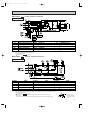
MSH-18NV - E1
MODEL WIRING DIAGRAM
INDOOR UNIT
❈
❈
❈
❈
❈
❈
NAME
SYMBOL
NAME
SYMBOL
C11
INDOOR FAN CAPACITOR
NR11
VARISTOR
F12
FUSE(93:)
RT11
F11
FUSE(3.15A)
MF
INDOOR FAN MOTOR
MV
VANE MOTOR
SYMBOL
NAME
TB
TERMINAL BLOCK
ROOM TEMPERATURE THERMISTOR
DSAR
SURGE ABSORBER
RT12
INDOOR COIL THERMISTOR
HIC1
DC/DC CONVERTER
IC141
HYBRID IC
52C
CONTACTOR
NOTE:1. For the outdoor electric wiring refer to the outdoor unit electric wiring diagram for servicing.
2. Use copper conductors only.(For field wiring)
3. Symbols below indicate.
: Terminal block,
: Connector
MODEL WIRING DIAGRAM
MUH-18NV - E1
OUTDOOR UNIT
❈
❈
❈
❈
❈
SYMBOL
NAME
SYMBOL
C1
COMPRESSOR CAPACITOR
MF
C65
OUTDOOR FAN MOTOR CAPACITOR
SURGE ABSORBER
DSAR
F61
FUSE(2A)
MC
COMPRESSOR<INNER THERMOSTAT>
NAME
SYMBOL
NAME
OUTDOOR FAN MOTOR
X62
REVERSING VALVE COIL RELAY
NR61
VARISTOR
21S4
REVERSING VALVE COIL
RT61
DEFROST THERMISTOR
52C
CONTACTOR
SR61
SOLID STATE RELAY
TB
TERMINAL BLOCK
NOTE:1. Use copper conductors only.(For field wiring)
2. Since the indoor and outdoor unit connecting wires have polarity, connect them according to the numbers.
3. Symbols below indicate.
: Terminal block,
: Connector
4. “❈”show the terminals with a lock mechanism, so they cannot be removed when you pull
the lead wire.
Be sure to pull the wire by pushing the locking lever(projected part) of the terminal with a finger.
1.Slide the sleeve.
2.Pull the wire while
pushing the locking
lever.
17
25/9/97 8:52 PM
MSH-24NV - E1
MODEL WIRING DIAGRAM
220-240V~ 3 TB❈ RED
220-240V~ 2 ❈ WHT
L
TO OUTDOOR
BRN
UNIT
CONNECTING N ❈ BLU
F12
HIC1
NF
BLU2
3 BLU
1
4
52C
❈3
TRANS
CN201
4
3
1
BLU
WHT
POWER
SUPPLY
CORD
~/N 220-240V
50Hz
CN
101
3
CIRCUIT BREAKER
GRN/YLW
CN
151
CN
102
F11
RT12
CN
112
IC141
CN
111
NR11
INDOOR UNIT
Page 18
CN
121
RT11
3
CN211
C11
OB207t-1qxp
4
2
1
BRN
YLW
GRY
WHT
RED
BLK
MF
ELECTRONIC CONTROL P.C BOARD
5
3
MV
RECEIVER
DISPLAY
P.C.BOARD
P.C.BOARD
REMOTE
CONTROLLER
SYMBOL
NAME
SYMBOL
C11
INDOOR FAN MOTOR CAPACITOR
F12
FUSE(93:)
F11
FUSE(3.15A)
MF
INDOOR FAN MOTOR
MV
VANE MOTOR
NAME
SYMBOL
NR11
VARISTOR
RT11
ROOM TEMPERATURE THERMISTOR
HIC1
RT12
INDOOR COIL THERMISTOR
NF
IC141
HYBRID IC
52C
NAME
TERMINAL BLOCK
TB
DC/DC CONVERTER
NOISE FILTER
CONTACTOR
NOTE:1. For the outdoor electric wiring refer to the outdoor unit electric wiring diagram for servicing.
2. Use copper conductors only.(For field wiring)
3. Symbols below indicate.
: Terminal block,
: Connector
MODEL WIRING DIAGRAM
MUH-24NV - E1
X1
OUTDOOR UNIT
6
1
TB2 26F1
N❈
RED 7
BLU 8
DSAR WHT
VLT
BLU
SYMBOL
NAME
C1
COMPRESSOR CAPACITOR
MF
C2
OUTDOOR FAN MOTOR CAPACITOR
NR61
VARISTOR
CR
YLW
52C
YLW
CN721
X62
DEICER
P.C. BOARD
CZ
WHT
52C1
WHT
1
2
C1
WHT C
RED S MC R
BLK
SYMBOL
NAME
NAME
SYMBOL
X62
REVERSING VALVE COIL RELAY
F
21S4
REVERSING VALVE COIL
26F1
THERMOSTAT (AIR FLOW CONTROL)
FUSE(2A)
SURGE ABSORBER 1
RT61
DEFROST THERMISTOR
52C
CONTACTOR
IC881
DC/DC CONVERTER
F61
FUSE(2A)
SR61
SOLID STATE RELAY
52C1
COMPRESSOR CONTACTOR
CR
SURGE ABSORBER 2
MC
COMPRESSOR<INNER THERMOSTAT> TB. TB2 TERMINAL BLOCK
FAN MOTOR RELAY
CZ
SURGE ABSORBER 3
DSAR
X1
NOTE:1. Use copper conductors only.(For field wiring)
2. Since the indoor and outdoor unit connecting wires have polarity, connect them according to the numbers.
3. Symbols below indicate.
: Terminal block,
: Connector
4. “❈”show the terminals with a lock mechanism, so they cannot be removed when you pull
the lead wire.
Be sure to pull the wire by pushing the locking lever(projected part) of the terminal with a finger.
18
CN661
TRANS
3 ❈4 ❈
BLU
<INNER THERMOSTAT>
2 3 4
IC881
❈
TAB20
X1
52C1
VLT
WHT
NAME
OUTDOOR FAN MOTOR
BLK
BLK
3
2
1
WHT
ORN RED
CN711 1
NR61
CN730
SR61
C2
F61
F
21S4
3
RED
220-240V~2 ❈
WHT
SYMBOL
RT61
BRN
5
1
TB
12VDC 3 ❈
GRN/YLW
TO INDOOR
UNIT
CONNECTING
MF
YLW YLW
5
BLK BLK
4
WHT WHT
3
ORN ORN
2
RED RED
1.Slide the sleeve.
2.Pull the wire while
pushing the locking
lever.
OB207t-1qxp
25/9/97 8:52 PM
Page 19
MSH-07NV - E2 MSH-09NV - E2 MSH-12NV - E2
MODELS WIRING DIAGRAM
INDOOR UNIT
TO OUTDOOR TB
L ❈ BRN
UNIT
CONNECTING
BRN
12VDC 3 ❈
SR11
HIC1
RED
F12
220-240V~ 2 ❈
BLU
WHT
BLU
1
LD101
GUARD
PLATE
POWER MONITOR,
RECEIVER
TRANS
RT11
BLK
1
GRY
3
CN
121
2
3
4
WHT
5
RED
6
YLW
BRN
3
2
1
CN211
ELECTRONIC CONTROL P.C BOARD
C11
MF
5
MV
P.C.BOARD
FOR MULTI SYSTEM
L
12VDC 3
TO OUTDOOR
UNIT
CONNECTING
CN
151
5
CIRCUIT BREAKER
NR11
F11
CN
122
RT12
CN
111
❈
3
❈ 4 52C
CN201
3
2
1
1
2
BLU
GRN/YLW
GRN/YLW
N ❈
BLU
BLU
POWER
SUPPLY
CORD
~/N 220-240V
50Hz
CN
112
2
REMOTE
N
CONTROLLER
SYMBOL
NAME
SYMBOL
C11
INDOOR FAN MOTOR CAPACITOR
F12
FUSE(93:)
F11
FUSE(3.15A)
MF
INDOOR FAN MOTOR
NAME
SYMBOL
NR11
VARISTOR
RT11
ROOM TEMPERATURE THERMISTOR
HIC1
DC/DC CONVERTER
RT12
INDOOR COIL THERMISTOR
SR11
SOLID STATE RELAY
52C
TERMINAL BLOCK
TB
CONTACTOR
NAME
VANE MOTOR
MV
NOTE:1. For the outdoor electric wiring refer to the outdoor unit electric wiring diagram for servicing.
2. Use copper conductors only.(For field wiring)
3. Symbols below indicate.
: Terminal block,
: Connector
MODELS WIRING DIAGRAM
TB
3
❈ RED
TO INDOOR
UNIT
CONNECTING
12VDC
220-240V~
2
N
21S4
CN661
CN721
F61
MF
X62
SR61
1
CN730
❈
❈
BLK
RT61
BLK
MUH-07NV - E2 MUH-09NV - E2
OUTDOOR UNIT
1 RED
2 WHT
3
4 BLK
CN711
C65
NR61
IC881
TRANS
BLU
TAB20
52C
WHT
❈4 3 ❈
X62
DEICER P.C. BOARD
WHT C
BLU
GRN/YLW
SYMBOL
NAME
SYMBOL
C1
COMPRESSOR CAPACITOR
MF
F61
FUSE(2A)
NR61
MC
COMPRESSOR<INNER THERMOSTAT>
RT61
SR61
❈
C1
❈
RED S
BLK
MC R
SYMBOL
NAME
SYMBOL
NAME
X62
REVERSING VALVE COIL RELAY
C65
FAN MOTOR CAPACITOR
VARISTOR
21S4
REVERSING VALVE COIL
IC881
DC/DC CONVERTER
DEFROST THERMISTOR
52C
CONTACTOR
TB
TERMINAL BLOCK
NAME
OUTDOOR FAN MOTOR
<INNER THERMOSTAT>
SOLID STATE RELAY
NOTE:1. Use copper conductors only.(For field wiring)
2. Since the indoor and outdoor unit connecting wires have polarity, connect them according to the numbers.
3. Symbols below indicate.
: Terminal block,
: Connector
4. “❈”show the terminals with a lock mechanism, so they cannot be removed when you pull
the lead wire.
Be sure to pull the wire by pushing the locking lever(projected part) of the terminal with a finger.
1.Slide the sleeve.
2.Pull the wire while
pushing the locking
lever.
19
OB207t-1qxp
25/9/97 8:52 PM
Page 20
MODEL WIRING DIAGRAM
MUH-12NV - E2
OUTDOOR UNIT
BLK
TB
N
CN661
MF
CN721
1
CN730
X62
SR61
❈ WHT
❈ BLU
❈
TAB20
TRANS
X62
3❈
DEICER P.C.BOARD
C1
BLU
RED
NAME
SYMBOL
NAME
OUTDOOR FAN MOTOR
C
WHT
S
BLK
SYMBOL
RED RED
1
1
WHT ORN
2
2
WHT
3
3
BLK
4
4 BLK
CN711
52C
❈4
GRN/YLW
C65
RED
NR61
220-240V~ 2
❈
IC881
3
F61
TO
INDOOR UNIT
CONNECTING
12VDC
BLK
21S4
RT61
SYMBOL
NAME
MC
R
SYMBOL
NAME
FAN MOTOR CAPACITOR
C1
COMPRESSOR CAPACITOR
X62
REVERSING VALVE COIL RELAY
C65
F61
FUSE(2A)
NR61
VARISTOR
21S4
REVERSING VALVE COIL
IC881
DC/DC CONVERTER
MC
COMPRESSOR<INNER THERMOSTAT>
RT61
DEFROST THERMISTOR
52C
CONTACTOR
TB
TERMINAL BLOCK
SR61
MF
<INNER THERMOSTAT>
SOLID STATE RELAY
NOTE:1. Use copper conductors only.(For field wiring)
2. Since the indoor and outdoor unit connecting wires have polarity, connect them according to the numbers.
3. Symbols below indicate.
: Terminal block,
: Connector
4. “❈”show the terminals with a lock mechanism, so they cannot be removed when you pull
the lead wire.
Be sure to pull the wire by pushing the locking lever(projected part) of the terminal with a finger.
20
1.Slide the sleeve.
2.Pull the wire while
pushing the locking
lever.
OB207t-1qxp
25/9/97 8:52 PM
Page 21
MSH-18NV - E2
MODEL WIRING DIAGRAM
INDOOR UNIT
❈
❈
❈
❈
❈
❈
~/N
FOR MULTI SYSTEM
TO OUTDOOR 12VDC
UNIT
CONNECTING
L
3
2
N
;
NAME
SYMBOL
NAME
SYMBOL
SYMBOL
NAME
NR11
VARISTOR
FUSE(93:)
RT11
ROOM TEMPERATURE THERMISTOR
DSAR
SURGE ABSORBER
FUSE(3.15A)
RT12
INDOOR COIL THERMISTOR
HIC1
DC/DC CONVERTER
MF
INDOOR FAN MOTOR
IC141
HYBRID IC
MV
VANE MOTOR
C11
INDOOR FAN CAPACITOR
F12
F11
TB
TERMINAL BLOCK
CONTACTOR
52C
NOTE:1. For the outdoor electric wiring refer to the outdoor unit electric wiring diagram for servicing.
2. Use copper conductors only.(For field wiring)
3. Symbols below indicate.
: Terminal block,
: Connector
MODEL WIRING DIAGRAM
MUH-18NV - E2
OUTDOOR UNIT
❈
❈
❈
❈
❈
SYMBOL
NAME
C1
COMPRESSOR CAPACITOR
MF
OUTDOOR FAN MOTOR
X62
REVERSING VALVE COIL RELAY
C65
OUTDOOR FAN MOTOR CAPACITOR
NR61
VARISTOR
21S4
REVERSING VALVE COIL
52C
CONTACTOR
NAME
SYMBOL
SURGE ABSORBER
RT61
DEFROST THERMISTOR
F61
FUSE(2A)
SR61
SOLID STATE RELAY
MC
COMPRESSOR<INNER THERMOSTAT>
DSAR
TB
SYMBOL
IC881
NAME
DC/DC CONVERTER
TERMINAL BLOCK
NOTE:1. Use copper conductors only.(For field wiring)
2. Since the indoor and outdoor unit connecting wires have polarity, connect them according to the numbers.
3. Symbols below indicate.
: Terminal block,
: Connector
4. “❈”show the terminals with a lock mechanism, so they cannot be removed when you pull
the lead wire.
Be sure to pull the wire by pushing the locking lever(projected part) of the terminal with a finger.
1.Slide the sleeve.
2.Pull the wire while
pushing the locking
lever.
21
25/9/97 8:52 PM
MSH-24NV - E2
Page 22
MODEL WIRING DIAGRAM
TB
220-240V~ 3 ❈ RED
220-240V~ 2 ❈ WHT
L
TO OUTDOOR BRN
UNIT
CONNECTING N ❈ BLU
F12
HIC1
NF
BLU 2
3BLU
1
4
❈3 52C
CN201
4
3
1
BLU
TRANS
F11
WHT
POWER
SUPPLY
CORD
~/N 220-240V
50Hz
CN
101
3
CIRCUIT BREAKER
GRN/YLW
CN
151
CN
102
3
RT12
CN
112
IC141
CN
111
RT11
3
CN
121
C11
INDOOR UNIT
NR11
OB207t-1qxp
CN211
4
2
1
BRN
YLW
GRY
WHT
RED
BLK
MF
ELECTRONIC CONTROL P.C BOARD
5
MV
RECEIVER
DISPLAY
P.C.BOARD
P.C.BOARD
REMOTE
CONTROLLER
NAME
SYMBOL
NAME
SYMBOL
NAME
SYMBOL
C11
INDOOR FAN CAPACITOR
NR11
VARISTOR
TB
TERMINAL BLOCK
F12
FUSE(93:)
RT11
ROOM TEMPERATURE THERMISTOR
NF
NOISE FILTER
F11
FUSE(3.15A)
RT12
INDOOR COIL THERMISTOR
HIC1
MF
INDOOR FAN MOTOR
IC141
HYBRID IC
MV
VANE MOTOR
DC/DC CONVERTER
CONTACTOR
52C
NOTE:1. For the outdoor electric wiring refer to the outdoor unit electric wiring diagram for servicing.
2. Use copper conductors only.(For field wiring)
3. Symbols below indicate.
: Terminal block,
: Connector
MODEL WIRING DIAGRAM
MUH-24NV - E2
OUTDOOR UNIT
X1
6
❈
C2
CN730
WHT
ORN
RED
RED 8
TB2 26F1 BLU 7
BLU
X1
VLT
N❈
DSAR WHT
A1
SYMBOL
NAME
SYMBOL
C1
COMPRESSOR CAPACITOR
MF
VLT
BLK
BLK
2 3 4
3
2
1
RED
220-240V~ 2 ❈ WHT F
CN711 1
52C1
CR
WHT
A2
CN661
SR61
TB
3
21S4
BRN
IC881
❈
TAB20
TRANS
52C
YLW
DEICER
P.C. BOARD
3 ❈ 4❈
YLW
WHT
CZ
WHT
52C1
WHT C
1
2
C1
RED S MC R
BLK
NAME
SYMBOL
BLU
CN721
X62
NR61
12VDC
GRN/YLW
TO INDOOR
UNIT
CONNECTING
MF
RT61
5
F61
YLW 5 YLW 1
BLK 4 BLK
WHT 3 WHT 3
ORN 2 ORN
RED 1 RED
NAME
OUTDOOR FAN MOTOR
X62
REVERSING VALVE COIL RELAY
NR61
VARISTOR
21S4
REVERSING VALVE COIL
DSAR
SURGE ABSORBER 1
RT61
DEFROST THERMISTOR
52C
CONTACTOR
CR
SURGE ABSORBER 2
SR61
SOLID STATE RELAY
52C1
COMPRESSOR CONTACTOR
TB,TB2
TERMINAL BLOCK
IC881
DC/DC CONVERTER
X1
FAN MOTOR RELAY
C2
FAN MOTOR CAPACITOR
CZ
SURGE ABSORBER 3
F61
FUSE(2A)
MC
COMPRESSOR<INNER THERMOSTAT>
F
26F1
FUSE(2A)
THERMOSTAT (AIR FLOW CONTROL)
NOTE:1. Use copper conductors only.(For field wiring)
2. Since the indoor and outdoor unit connecting wires have polarity, connect them according to the numbers.
3. Symbols below indicate.
: Terminal block,
: Connector
4. “❈”show the terminals with a lock mechanism, so they cannot be removed when you pull
the lead wire.
Be sure to pull the wire by pushing the locking lever(projected part) of the terminal with a finger.
22
1.Slide the sleeve.
2.Pull the wire while
pushing the locking
lever.
25/9/97 8:52 PM
Page 23
MSH-18NV - E3
HIC1
RED
BLU
WHT
N❈
BLU
2
1
BLU
BLU
BLU
BRN
DSAR
POWER
SUPPLY
CORD
~/N 220-240V
50Hz
TRANS
LD1
CN
151 ELECTRONIC CONTROL P.C BOARD
CN CN
101 102
CN
112
RT12
3
CN
121
F11
CN211
4
2
1
BRN
YLW
GRY
WHT
RED
BLK
CN
111
MF
RT11
5
GRN/YLW
CIRCUIT BREAKER
❈
4
❈ 3 52C
CN201
3
1
NR11
F12
220-240V~ 2 ❈
IC141
C11
TO OUTDOOR TB
UNIT
L ❈ BRN
CONNECTING
BRN
12VDC 3 ❈
GRN/YLW
INDOOR UNIT
MODEL WIRING DIAGRAM
3
3
MV
RECEIVER
DISPLAY
P.C.BOARD
P.C.BOARD
FOR MULTI SYSTEM
L
12VDC 3
TO OUTDOOR
2
UNIT
N
REMOTE
CONTROLLER
CONNECTING
NAME
SYMBOL
NAME
SYMBOL
NAME
SYMBOL
NR11
VARISTOR
FUSE(93:)
RT11
ROOM TEMPERATURE THERMISTOR
DSAR
SURGE ABSORBER
FUSE(3.15A)
RT12
INDOOR COIL THERMISTOR
HIC1
DC/DC CONVERTER
MF
INDOOR FAN MOTOR
IC141
HYBRID IC
MV
VANE MOTOR
C11
INDOOR FAN CAPACITOR
F12
F11
TERMINAL BLOCK
TB
CONTACTOR
52C
NOTE:1. For the outdoor electric wiring refer to the outdoor unit electric wiring diagram for servicing.
2. Use copper conductors only.(For field wiring)
3. Symbols below indicate.
: Terminal block,
: Connector
N
WHT
WH
T
❈ BLU
1
DSAR
VLT
MF
CN720
X62
❈ F61
TAB21
❈
GRN/YLW
CN721
CN661
VLT
BLK
❈
CN730
BLK
220-240V~ 2
RED
SR61
1 RED 1 RED
2 WHT 2 ORN
WHT
3
3
BLK
BLK
4
4
NR61
TB
❈
IC881
3
12VDC
52C
21S4
RT61
C65
MODEL WIRING DIAGRAM
MUH-18NV - E3
OUTDOOR UNIT
TO
INDOOR UNIT
CONNECTING
OB207t-1qxp
TRANS
X62 CN711
TAB20
DEICER P.C.BOARD
WHT NO
52C
COM
C1
BLU
WHT
C
RED
S
BLK
MC
R
SYMBOL
NAME
C1
COMPRESSOR CAPACITOR
MF
OUTDOOR FAN MOTOR
X62
REVERSING VALVE COIL RELAY
C65
OUTDOOR FAN MOTOR CAPACITOR
NR61
VARISTOR
21S4
REVERSING VALVE COIL
52C
CONTACTOR
NAME
SYMBOL
SURGE ABSORBER
RT61
DEFROST THERMISTOR
F61
FUSE(2A)
SR61
SOLID STATE RELAY
MC
COMPRESSOR<INNER THERMOSTAT>
DSAR
TB
SYMBOL
IC881
NAME
DC/DC CONVERTER
TERMINAL BLOCK
NOTE:1. Use copper conductors only.(For field wiring)
2. Since the indoor and outdoor unit connecting wires have polarity, connect them according to the numbers.
3. Symbols below indicate.
: Terminal block,
: Connector
4. “❈”show the terminals with a lock mechanism, so they cannot be removed when you pull
the lead wire.
Be sure to pull the wire by pushing the locking lever(projected part) of the terminal with a finger.
1.Slide the sleeve.
2.Pull the wire while
pushing the locking
lever.
23
OB207t-1qxp
6
25/9/97 8:53 PM
Page 24
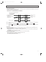
REFRIGERANT SYSTEM DIAGRAM
Unit:mm
MSH-07NV - E1
MSH-07NV - E2
INDOOR UNIT
Refrigerant pipe [ 9.52
(Option)
MUH-07NV - E1
MUH-07NV - E2
OUTDOOR UNIT
Muffler Reversing valve
(4-way valve)
(with heat insulator)
Indoor
heat
exchanger
Indoor coil
thermistor
RT12
Flared connection
Stop valve
(with service Defrost
thermistor
port)
RT61
Strainer
Room temperature
thermistor
RT11
Outdoor
heat
exchanger
Capillary tube
[1.4x800 (2 pcs)
Accumulator
Capillary tube
[1.6x750
Check
valve
Flared connection
Reversing valve coil
(4-way valve coil)
heating ON
cooling OFF
Strainer
Refrigerant pipe [6.35
(Option)
Stop valve
Capillary tube
[1.4x850
Refrigerant flow in cooling
(with heat insulator)
Refrigerant flow in heating
Unit:mm
MSH-09NV - E1
MSH-09NV - E2
INDOOR UNIT
Refrigerant pipe [9.52
(Option)
MUH-09NV - E1
MSH-09NV - E2
OUTDOOR UNIT
Muffler Reversing valve
(4-way valve)
(with heat insulator)
Indoor
heat
exchanger
Indoor coil
thermistor
RT12
Flared connection
Stop valve
(with service Defrost
thermistor
port)
RT61
Strainer
Room temperature
thermistor
RT11
Outdoor
heat
exchanger
Capillary tube
[1.4x800 (2 pcs)
Accumulator
Check
valve
Flared connection
Strainer
Refrigerant pipe [6.35
(Option)
Stop valve
Capillary tube
[1.6x1300
Capillary tube
[1.6x400
Reversing valve coil
(4-way valve coil)
heating ON
cooling OFF
Refrigerant flow in cooling
(with heat insulator)
24
Refrigerant flow in heating
OB207t-1qxp
25/9/97 8:53 PM
Page 25
Unit:mm
MSH-12NV - E1
MSH-12NV - E2
INDOOR UNIT
Refrigerant pipe [12.7
(Optional)
(with heat insulator)
Indoor
heat
exchanger
Indoor coil
thermistor
RT12
Flared connection
MUH-12NV - E1
MUH-12NV - E2
Reversing valve
(4-way valve)
OUTDOOR UNIT
Muffler
Stop valve
(with service port)
Outdoor
heat
exchanger
Defrost
thermistor
RT61
RT11
Room temperature
thermistor
RT11
Accumulator
Compressor
Capillary tube
[1.6x400
Flared connection
Capillary tube
[1.4x500
Strainer
Refrigerant pipe
(Option) [6.35
Stop valve
Indoor
heat
exchanger
Indoor coil
thermistor
RT12
Distributor
MUH-18NV
MUH-18NV
MUH-18NV
OUTDOOR
- E1
- E2
- E3
UNIT
Muffler
Strainer
Stop valve
(with service port)
Defrost
thermistor
RT61
Flared connection
Room temperature
thermistor
RT11
Refrigerant flow in heating
Unit:mm
Reversing valve
(4- way valve)
Refrigerant pipe [15.88
(Option)
(with heat insulator)
Refrigerant flow in cooling
Check
valve
(with heat insulator)
MSH-18NV - E1
MSH-18NV - E2
MSH-18NV - E3
INDOOR UNIT
Reversing valve coil
(4-way valve coil)
heating ON
cooling OFF
Outdoor
heat
exchanger
Accumulator
Compressor
Capillary tube
[1.6x750
(2 pcs)
Flared connection
Strainer
Refrigerant pipe
(Option) [6.35
(with heat insulator)
Capillary tube
[2.0X800
Stop valve
Check
valve
Reversing valve coil
(4-way valve coil)
heating ON
cooling OFF
Refrigerant flow in cooling
Refrigerant flow in heating
25
OB207t-1qxp
25/9/97 8:53 PM
Page 26
Unit:mm
MSH-24NV - E1
MSH-24NV - E2
INDOOR UNIT
Indoor
heat
exchanger
Refrigerant pipe [15.88
(Option)
(with heat insulator)
Indoor coil
thermistor
RT12
Distributor
MUH-24NV - E1
MUH-24NV - E2
OUTDOOR UNIT
Reversing valve
(4- way valve)
Muffler
Strainer
Ball valve
Outdoor
heat
exchanger
Flared connection
Room temperature
thermistor
RT11
Accumulator
Defrost
thermistor
RT61
Compressor
Flared connection
Check
valve
Capillary tube
[1.6X350
Discharge pressure
regurator open
23.5 kgf/J
Strainer
Ball valve
Refrigerant pipe
with Service port
(Option) [9.52
(with heat insulator)
Capillary tube
[2.0X350
26
Capillary tube
[2.4X200
Check
valve
Refrigerant flow in cooling
Refrigerant flow in heating
OB207t-1qxp
25/9/97 8:53 PM
Page 27
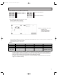
MAX. REFRIGERANT PIPING LENGTH
Refrigerant piping
Max. length : m
Models
A
MSH-07NV -
E1
MSH-09NV -
E1
MSH-07NV -
E2
MSH-09NV -
E2
MSH-12NV MSH-12NV -
E1
MSH-18NV -
E1
MSH-18NV MSH-18NV -
E2
MSH-24NV MSH-24NV -
E1
10
Piping size O.D : mm
Length of connecting pipe : m
Liquid
Indoor unit
Outdoor unit
12.7
6.35
0.43
0
15.88
9.52
Gas
9.52
E2
15
E3
E2
MAX. HEIGHT DIFFERENCE
ADDITIONAL REFRIGERANT CHARGE(R-22 : g)
Refrigerant piping length (one way)
Outdoor unit precharged
Models
(up to 7m)
MSH-07NV -
E1
MSH-09NV -
E1
MSH-07NV -
E2
MSH-09NV -
E2
MSH-12NV MSH-12NV -
E1
MSH-18NV -
E1
MSH-18NV -
E2
MSH-18NV -
E3
7m
10m
0
150
15m
850
1150
E2
400
1800
Calculation : Xg=50g/m ✕ (A-7)m
Refrigerant piping length (one way)
Outdoor unit precharged
Models
MSH-24NV -
E1
MSH-24NV -
E2
(up to 7m)
7m
10m
15m
2400
0
195
520
Calculation : Xg=65g/m ✕ (A-7)m
27
OB207t-1qxp
25/9/97 8:53 PM
Page 28
EVACUATION PROCEDURES(AIR PURGE)
Connect the refrigerant pipes (both the liquid and gas pipes)
between the indoor and the outdoor units.
Remove the service port cap of the stop valve on the side of the outdoor unit gas pipe.(The stop valve will not
work in its initial state fresh out of the factory (totally closed with cap on))
When vacuuming
Connect the gage manifold valve and the vacuum pump to
the service port of the stop valve on the liquid pipe side of the
outdoor unit.
Run the vacuum pump for more than 15 minutes and at this
time confirm that the pressure gage indicates – 0.1 Mpa.
Check the vacuum with the gage manifold valve, then close
the gage manifold valve, and stop the vacuum pump.
Leave it as it is for one or two minutes. Make sure the pointer
of the gage manifold valve remains in the same position.
,
Remove the gage manifold valve quickly from the service port of the stop valve.
After refrigerant pipes are connected and evacuated, fully open all stop valves on gas and liquid pipe sides.
Operating without fully opening lowers the performance and causes trouble.
Pipe length :
7m maximum
No gas charge
is needed
Pipe length
exceeding 7m
Charge the prescribed
amount of gas
Tighten the cap to the service port to obtain the initial status.
Retighten the cap.
Leak test
28
OB207t-2qxp
25/9/97 8:54 PM
7
Page 29
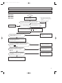
PERFORMANCE CURVES
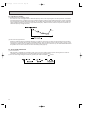
The standard data contained in these specifications apply only to the operation of the air conditioner under normal conditions,
since operating conditions vary according to the areas where these units are installed. The following information has been provided to clarify the operating characteristics of the air conditioner under the conditions indicated by the performance curve.
(1) GUARANTEED VOLTAGE
Rated voltage : ±10% (198 ~ 264V),50Hz
(2) AIR FLOW
Air flow should be set at MAX.
(3) MAIN READINGS
(1) Indoor intake air wet-bulb temperature :
(2) Indoor outlet air wet-bulb temperature :
(3) Outdoor intake air dry-bulb temperature :
(4) Total input:
(5) Indoor intake air dry-bulb temperature :
(6) Outdoor intake air wet-bulb temperature :
(7) Total input :
°CWB
°CWB
°CDB
W
°CDB
°CWB
W
}
Cooling
}
Heating
Indoor air wet/dry-bulb temperature difference on the left side of the chart on next page shows the difference between the
indoor intake air wet/dry-bulb temperature and the indoor outlet air wet/dry-bulb temperature for your reference at service.
How to measure the indoor air wet-bulb/dry-bulb temperature difference
1.
2.
3.
4.
5.
6.
7.
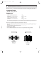
Attach at least 2 sets of wet-and dry-bulb thermometers to the indoor air intake as shown in the figure, and at least 2 sets
of wet-and dry-bulb thermometers to the indoor air outlet. The thermometers must be attached to the position where air
speed is high.
Attach at least 2 sets of wet-and dry-bulb thermometers to the outdoor air intake.
Cover the thermometers to prevent direct rays of the sun.
Check that the air filter is cleaned.
Open windows and doors of room.
Press the EMERGENCY OPERATION switch once(twice) to start the EMERGENCY COOL(HEAT) MODE.
When system stabilizes after more than 15 minutes, measure temperature and take an average temperature.
10 minutes later, measure temperature again and check that the temperature does not change.
INDOOR UNIT
OUTDOOR UNIT
Wet-and dry-bulb
thermometers
Wet-and dry-bulb
thermometers
29
OB207t-2qxp
25/9/97 8:54 PM
Page 30
12.0
14.0
11.4
12.7
10.4
11.5
9.4
10.3
9.1
9.2
7.6
8.1
24
24
8.5
25.5 28.7
28.0
28.0
18.4
23.5 26.5
25.9
25.9
16.9
21.6 24.3
23.7
23.7
15.3
19.6 22.5
21.6
21.6
13.8
17.6 19.9
19.4
19.4
12.3
15.6 17.7
17.2
17.2
10.7
13.7 15.5
15.1
15.1
9.2
11.7 13.2
12.9
12.9
24
24
19.9
NOTE:The above curves are for the heating operation without any frost.
OUTDOOR LOW PRESSURE AND OUTDOOR UNIT CURRENT
COOL operation
① Both indoor and outdoor unit are under the same temperature/humidity condition.
Dry-bulb temperature
Relative humidity(%)
20
50
25
60
30
70
➁ Air flow should be set at MAX.
③ The unit of pressure has been changed to MPa on the international system of units(SI unit system).
f • G)
The conversion factor is : 1(MPa • G) =10.2(kgf/f
7
0.7
6
0.6
MUH-07NV - E1
220/240V
5
0.5
4
0.4
3
0.3
Ambient temperature(˚C)
Ambient humidity(%)
30
MUH-07NV - E1
E2
Outdoor unit current (A)
Outdoor low pressure
(kgf/F•G)(MPa•G)
E2
220V
240V
Ambient temperature(˚C)
Ambient humidity(%)
25/9/97 8:54 PM
(kgf/F•G)(MPa•G)
Outdoor low pressure
7
0.7
6
0.6
5
0.5
Page 31
MUH-09NV - E1
MUH-09NV - E1
E2
220/240V
4
0.4
3
0.3
240V
Ambient temperature(˚C)
Ambient humidity(%)
Ambient temperature(˚C)
Ambient humidity(%)
7
0.7
6
0.6
5
0.5
4
0.4
3
0.3
MUH-12NV - E1
MUH-12NV - E1
E2
Outdoor unit current (A)
Outdoor low pressure
(kgf/F•G)(MPa•G)
220/240V
240V
Ambient temperature(˚C)
Ambient humidity(%)
E2
220/240V
6
MUH-18NV - E1
E3
0.6
5
0.5
4
0.4
3
0.3
2
0.2
(kgf/F•G)(MPa•G)
240V
Ambient temperature(˚C)
Ambient humidity(%)
MUH-24NV - E1
MUH-24NV - E1
E2
0.7
0.6
5
0.5
4
0.4
3
0.3
2
0.2
E2
13
220V
Outdoor unit current (A)
Outdoor low pressure
6
E3
220V
Ambient temperature(˚C)
Ambient humidity(%)
7
E2
0.7
Outdoor unit current (A)
Outdoor low pressure
7
MUH-18NV - E1
E2
220V
Ambient temperature(˚C)
Ambient humidity(%)
(kgf/F•G)(MPa•G)
E2
220V
Outdoor unit current (A)
OB207t-2qxp
Ambient temperature(˚C)
Ambient humidity(%)
220V
12
240V
Ambient temperature(˚C)
Ambient humidity(%)
31
OB207t-2qxp
25/9/97 8:54 PM
Page 32
HEAT operation
Condition indoor:Dry bulb temperature 20.0°C
Wet bulb temperature 14.5°C
MUH-12NV - E1
E2
220V
240V
Outdoor unit current (A)
Outdoor unit current (A)
MUH-07NV - E1
Outdoor:Dry bulb temperature 7,15,20°C
Wet bulb temperature 6,12,14.5°C
220V
240V
Ambient temperature(˚C)
220V
240V
Ambient temperature(˚C)
MUH-18NV - E1
E2
Outdoor unit current (A)
Outdoor unit current (A)
MUH-09NV - E1
E2
E2
220V
240V
Ambient temperature(˚C)
Ambient temperature(˚C)
MUH-24NV - E1
E2
Outdoor unit current (A)
13
220V
12
240V
11
10
9
Ambient temperature(˚C)
32
E3
OB207t-2qxp
25/9/97 8:54 PM
8
Page 33
MICROPROCESSOR CONTROL
Wireless remote controller
MSH-07NV
MSH-18NV
MSH-07NV
MSH-18NV
- E1
- E1
- E2
- E2
MSH-09NV
MSH-24NV
MSH-09NV
MSH-24NV
- E1
- E1
- E2
- E2
MSH-12NV - E1
MSH-12NV - E2
MSH-18NV - E3
Once the controls are set, the same operation mode can be
repeated by simply turning the OPERATE/STOP button ON.
Indoor unit receives the signal with a beep tone.
When the system turns off, 3-minute time delay will operate to
protect system from overload and compressor will not restart
for 3 minutes.
8-1. “I FEEL CONTROL” (
) OPERATION
(1) Press OPERATE/STOP button on the remote controller.
OPERATION INDICATOR lamp of the indoor unit will turn
on with a beep tone.
(2) Press OPERATION SELECT button to set “I FEEL CONTROL”(
). Then a beep tone is heard.
(3) The operation mode is determined by the initial room
temperature at start-up of the operation.
Initial room temperature
Mode
more than 25:
COOL mode of
"I FEEL CONTROL"
23: to 25:
DRY mode of
"I FEEL CONTROL"
less than 23:
HEAT mode of
"I FEEL CONTROL"
● Once the mode is fixed, the mode will not change by
room temperature afterwards.
● Under the ON-TIMER (
) operation, mode is determined according to the room temperature as the operation starts.
● When the system is stopped with the OPERATE/STOP
button on the remote controller, and restarted within 2
hours in “I FEEL CONTROL” (
) mode, the system
operates in previous mode automatically regardless of
the room temperature.
Example
Previous operation
COOL mode of
“I FEEL CONTROL”
or COOL mode
INDOOR UNIT DISPLAY SECTION
Restart
COOL mode of
“I FEEL CONTROL”
● When the system is restarted after 2 hours, the operation
mode is determined by the initial room temperature at
start-up of the operation.
Restart
Example
COOL or DRY or
HEAT mode of “I FEEL
Previous operation
CONTROL” that deterCOOL mode of
mined by initial room
“I FEEL CONTROL”
temperature at start-up
of the operation.
or COOL mode
33
OB207t-2qxp
25/9/97 8:55 PM
Page 34
(4) The initial set temperature is decided by the initial room temperature.
Model
Initial room temperature
COOL mode of
"I FEEL CONTROL"
26: or more
Initial set temperature
24:
❈1
26: or less
DRY mode of
"I FEEL CONTROL"
23: or 25:
HEAT mode of
"I FEEL CONTROL"
23: or less
Initial room temperature
minus 2:
Initial room temperature
minus 2:
26:
❈1 After the system restarts by the remote controller, the system operates with the previous set temperature regardless of
the initial set temperature.
The set temperature is calculated by the previous set temperature.
(5) TEMPERATURES buttons
In “I FEEL CONTROL” (
) mode, set temperature is decided by the microprocessor based on the room temperature.
In addition, set temperature is controlled by TOO WARM or TOO COOL buttons when you feel too cool or too warm.
Each time the TOO WARM or TOO COOL button is pressed,the indoor unit receives the signal and emits a beep tone.
● Fuzzy control
When the TOO COOL or TOO WARM button is pressed, the microprocessor changes the set temperature, considering
the room temperature, the frequency of pressing TOO COOL or TOO WARM button and the user’s preference to heat or
cool. So this is called “Fuzzy control”, and works only in “I FEEL CONTROL” mode.
In DRY mode of “I FEEL CONTROL”, the set temperature doesn’t change.
▲ TOO
COOL … To raise the set temperature 1~2 degrees(°C)
▼ TOO
WARM … To lower the set temperature 1~2 degrees(°C)
34
OB207t-2qxp
25/9/97 8:55 PM
Page 35
— COOL mode of “I FEEL CONTROL” —
ON
ON
Compressor and
outdoor fan motor
OFF
Indoor fan motor
ON
OFF
Run continuously in cooling mode
NOTE : Coil frost prevention during COOL mode of “I FEEL CONTROL”
There are two types of controls in coil frost prevention.
① Temperature control
<MSH-07/09/12> When the indoor coil thermistor RT12 reads 4°C or below for 5 minutes, the coil frost prevention mode
starts.
<MSH-18/24>When the indoor coil thermistor RT12 reads 3°C or below, the coil frost prevention mode starts immediately.
However the coil frost prevention will not work for 5 minutes after the compressor starts.
The compressor stops and the indoor fan operates at the set speed for 5 minutes.
After that, if RT12 still reads below 4°C (MSH-07/09/12) or below 3°C (MSH-18/24) this mode prolonged until the RT12
reads over 4°C (MSH-07/09/12) or 3°C (MSH-18/24).
② Time control
When the three conditions below have been satisfied for 1 hour and 45 minutes, compressor stops for 3 minutes.
a. Compressor has been continuously operating.
b. Indoor fan speed is Lo or Me.
c. Room temperature is below 26°C.
When compressor stops, the accumulated time is cancelled and when compressor restarts, time counting starts from the
beginning.
Time counting also stops temporarily when the indoor fan speed becomes Hi or the room temperature exceeds
26°C.However, when two of the above conditions (b.and c.) are satisfied again.Time accumulation is resumed.
●Indoor fan operates at the set speed by FAN SPEED CONTROL button.
Followings are the fan speed in AUTO.
Initial temperature difference
Fan Speed
Room temperature minus set temperature : 2 degrees or more ··············································Hi
Room temperature minus set temperature : 1 degree or more and less than 2 degrees ·······Me
2 deg. 4 deg.
Room temperature minus set temperature : less than 1 degree··············································Lo
1 deg. 1.66 deg.
—DRY mode of “I FEEL CONTROL”—
The system for dry operation uses the same refrigerant circuit as the cooling circuit.
The compressor and the indoor fan are controlled by the temperature and the microprocessor.
By such controls, indoor flow amounts will be reduced in order to lower humidity without much room temperature
decrease.
The operation of the compressor and indoor fan is as follows.
1. When the room temperature is 23°C or over:
Compressor operates by temperature control and time control.
① Set temperature is controlled to fall 2°C as initial set temperature.
② When the thermostat is ON, the compressor repeats 8 minutes ON and 3 minutes OFF.
When the thermostat is OFF, the compressor repeats 4 minutes OFF and 1 minute ON.
Indoor fan and outdoor fan operate in the same cycle as the compressor.
2. When the room temperature is under 23°C.
When the thermostat is ON, the compressor repeats 2 minutes ON and 3 minutes OFF.
When the thermostat is OFF, the compressor repeats 4 minutes OFF and 1 minute ON.
35
OB207t-2qxp
25/9/97 8:55 PM
Page 36
Operation time chart
Example
ON
1st ON
OFF
Thermostat
Indoor fan
OFF
ON
Outdoor fan
compressor
ON
ON
ON
OFF
ON
OFF
8 min.
ON
OFF
1 min.
3 min.
4 min.
NOTE ● Coil frost prevention during DRY mode of “I FEEL CONTROL”
The operation is as same as coil frost prevention during COOL mode of “I FEEL CONTROL”.
However the indoor fan speed becomes the set speed or Lo.
— HEAT mode of “I FEEL CONTROL” —
1. Indoor fan speed control
(1) Followings are the fan speed in AUTO.
Initial temperature difference
Fan speed
Set temperature minus room temperature: 2 degrees or more················································· Hi
Set temperature minus room temperature: 1 degree or more and less than 2 degrees··········· Me
2 deg. 4 deg.
Set temperature minus room temperature: less than 1 degree················································· Lo
1 deg. 1.66 deg.
(2) Cold air prevention control
The fan runs at set speed when the indoor coil thermistor RT12 temperature exceeds 22°C. The fan operates at VLo
when the temperature is below 18°C. But the fan stops when the indoor fan operates at VLo and the temperature is
15°C or less.
NOTE : At initial in hysteresis this control works.
Released
Cold Air Prevention
18: 22:
(3) New warm air control.
When compressor starts in heating operation or after defrosting, the fan changes the speed due to the indoor coil thermistor RT12 temperature to blow out warm air.
After releasing of cold air prevention, when the indoor coil temperature is 37°C or above, the fan speed shifts to the set
speed, and when the fan speed is changed by the remote controller, the fan speed is the set speed.
When the indoor coil temperature is less than 37°C, the fan speed is controlled by time as below.
<Time condition> <Indoor fan speed>
less than 2 minutes ························Lo
2 minutes to 4 minutes···················Me
4 minutes or more ··························Hi
The upper limit of the fan speed is the set speed.
If the thermostat turns off, this operation changes to flow soft control.
(4) Flow soft control
After the thermostat turns off, the indoor fan operates at VLo.
NOTE : When the thermostat turns on, the fan operates at the set speed. Due to the cold air prevention control, the fan
does not start until the indoor coil thermistor RT12 reads 22°C or more.
36
OB207t-2qxp
25/9/97 8:55 PM
Page 37
2. High pressure protection
During heating operation, the outdoor fan motor is controlled by the indoor coil thermistor RT12 temperature for excess rise
protection of compressor discharge pressure.
Outdoor fan OFF : 52°C (MSH-07/09/12/24), 50°C (MSH-18)
Outdoor fan ON : 48°C (MSH-07/09/12/24), 46°C (MSH-18)
High pressure protection time chart
Indoor coil thermistor
RT12 temperature
52˚C(MSH-07/09/12/24)
50˚C(MSH-18)
Outdoor fan motor
turn OFF
48˚C(MSH-07/09/12/24)
46˚C(MSH-18)
Outdoor fan motor
turn ON
ON
ON
Outdoor fan motor
OFF
OFF
NOTE 1 :When the outdoor fan is OFF in heating, defrosting of outdoor heat exchanger is not detected by the defrost thermistor RT61.
NOTE 2 :When connected to MXZ-32NV- E1 outdoor unit,the MSH-07/09/12NV- E1 , MSH-07/09/12/18NV- E2 and
MSH-18NV- E3 indoor unit sends the data for the temperature to the outdoor unit according to the indoor coil temperature.For the further information,refer to the service manual No.OB185.
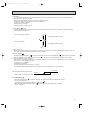
3. Defrostings
Defrostings of outdoor heat exchanger is controlled by DEICER P.C. board, with detection by the defrost thermistor RT61.
(1) Defrost starting conditions
When all conditions of a) ~ c) are satisfied, the defrosting operation starts.
a) Under the heat operation, the compressor cumulative operation time exceeds 40 minutes without the defrosting operation working.
b) The defrost thermistor RT61 reads - 3°C or less.
c) After releasing the high pressure protection 4 minutes and 15 seconds have elapsed.
(2) Defrost terminating conditions
When the condition d) or e) is satisfied, the defrosting operation stops.
d) The defrost thermistor RT61 reads 3.1°C or more.
e) The defrosting time exceeds 10 minutes.
37
OB207t-2qxp
25/9/97 8:55 PM
Page 38
(3) Defrosting time chart
Defrost thermistor RT61
3.1: or more
-3: or less
Outdoor 52C
relay(Compressor)
ON
OFF
X62
(Reversing valve coil)
ON
OFF
15 sec.
30 sec.
30 sec.
5~15 sec.
ON
SR61
Outdoor fan OFF
Defrost
counter
Indoor fan
ON
OFF
ON
Max 10 min.
❈
VLo
OFF
Indoor vane
Horizontal
Set position
NOTE1 ● When the indoor coil thermistor reads above 18°C, indoor fan operates at VLo for 30 seconds.
● When the indoor coil thermistor reads 18°C or less, the indoor fan stops.
NOTE2: Refer to the Service Manual OB185 when MSH-07/09/12NV- E1 , MSH-07/09/12/18NV- E2 , and MSH-18NVare connected with MXZ-32NV- E1 as multi system units.
38
E3
OB207t-2qxp
25/9/97 8:55 PM
Page 39
4. Reversing valve control
Heating · · · · · ON
Cooling · · · · · OFF
Dry · · · · · · · · OFF
NOTE1: The Reversing valve reverses for 5 seconds right before start-up of the compressor.
NOTE2: Refer to the Service Manual OB185 when MSH-07/09/12NV- E1 , MSH-07/09/12/18NVare connected with MXZ-32NV- E1 as multi system units.
Reversing valve
ON
OFF
ON
OFF
Outdoor fan
ON
OFF
Compressor
8-2. COOL (
(COOL / DRY)
(HEAT)
5 sec.
5 sec.
E2
, and MSH-18NV-
E3
ON
OFF
ON
OFF
ON
OFF
) OPERATION
(1) Press OPERATE/STOP button.
OPERATION INDICATOR of the indoor unit turns on with a beep tone.
(2) Select COOL mode.
(3) Set the TEMPERATURES button.
(TOO WARM or TOO COOL button)
The setting range is 16 ~ 31°C
✻ Indoor fan continues to operate regardless of
thermostat’s OFF-ON
✻ Coil frost prevention is as same as COOL
mode of “I FEEL CONTROL”
8-3. DRY (
) OPERATION
(1) Press OPERATE/STOP button.
OPERATION INDICATOR of the indoor unit
turns on with a beep tone.
(2) Select DRY mode.
(3) The microprocessor reads the room temperature and determines the set temperature. Set
temperature is as shown on the right chart.
Thermostat (SET TEMP.)does not work.
The other operations are same as DRY mode of
“I FEEL CONTROL”.
(4) DRY operation will not function when the room
temperature is 13°C or below.
(5) When DRY operation functions, the fan speed
is lower than cool operation.
8-4. HEAT (
) OPERATION
(1) Press OPERATE/STOP button.
OPERATION INDICATOR on the indoor unit turns on with a beep tone.
(2) Select HEAT mode.
(3) Press TEMPERATURES button (TOO WARM or TOO COOL button) to select the desired temperature.
The setting range is 16 ~ 31°C.
(4) Indoor fan speed control, high pressure protection, defrosting, heater control are the same as HEAT mode of “I FEEL
CONTROL”.
39
OB207t-2qxp
25/9/97 8:55 PM
Page 40
8-5. FAN MOTOR CONTROL
(1) Rotational frequency feedback control
The indoor fan motor is equipped with a rotational frequency sensor, and outputs signal to the microprocessor to feedback
the rotational frequency. Comparing the current rotational frequency with the target rotational frequency (Hi,Me,Lo,SLEEP),
the microprocessor controls SR11 (MSH-07/09/12), IC141 (MSH-18/24) and adjusts fan motor electric current to make the
current rotational frequency close to the target rotational frequency. With this control, when the fan speed is switched, the
rotational frequency changes smoothly.
SLEEP
(2) Fan motor lock-up protection
When the rotational frequency feedback signal has not output for 12 seconds, (or when the microprocessor cannot detect
the signal for 12 seconds) the fan motor is regarded locked-up. Then the electric current to the fan motor is shut off. 3 minutes later, the electric current is applied to the fan motor again. During the fan motor lock-up, the OPERATION INDICATOR
lamp flashes on and off to show the fan motor abnormality. (See page 49.)
8-6. AUTO VANE OPERATION
(1) Vane motor drive
MSH-N series is equipped with a stepping motor for the vane. The rotating direction, speed, and angle of the motor are
controlled by pulse signals (approx. 12V) transmitted from indoor microprocessor.
(2) The auto vane angle changes as follows by pressing the VANE CONTROL (
) button.
40
OB207t-2qxp
25/9/97 8:55 PM
Page 41
(3) Positioning
The vane is once pressed to the vane stopper below to confirm the standard position and then set to the desired angle.
The positioning is decided as follows.
(a) When the OPERATE/STOP button is pressed. (POWER ON/OFF)
(b) When the vane control is changed from AUTO to MANUAL.
(c) When the SWING is finished.
(d) When the test run starts.
(e) When the power supply turns ON.
(4) VANE AUTO (
) mode
In VANE AUTO mode, the microprocessor automatically determines the vane angle and operation to make the optimum
room-temperature distribution.
① In COOL and DRY operation
Vane angle is fixed to Angle 1.
➁ In HEAT operation
Vane angle is fixed to Angle 4.
(5) Dew prevention
During COOL or DRY operation at vane Angle 4 or 5 when the compressor cumulative operation time exceeds 1 hour, the
vane angle automatically changes to Angle 1 for dew prevention.
(6) SWING MODE (
)
By pressing the SWING button (
) vane swings vertically. The remote controller displays “
”. SWING mode is cancelled
when the SWING button or VANE CONTROL button (
) is pressed or the operation stops or changes to other mode.
(7) Cold air prevention in HEAT operation
When either of the following conditions occurs in HEAT operation, the horizontal vane angle changes to Angle 1 automatically to prevent cold air blowing on users.
① Compressor is not operating.
➁ Defrosting is performed.
➂ Indoor coil thermistor RT12 reads 24: or below.
➃ Indoor coil thermistor RT12 temperature is raising from 24°C or below, but it does not exceed 28:.
Set position
Indoor coil thermistor RT12 temperature
Angle 1
NOTE:At initial in hysteresis this control works.
8-7. SLEEP MODE (
24:
28:
)
• When the SLEEP button (
indoor unit is decreased.
) is pressed, the indoor fan speed drops and the air flow sound from the
• The indications of the remote controller are “
• When the FAN SPEED CONTROL button (
mode is released.
” and “
”.
) is pressed during the SLEEP mode, the SLEEP
41
OB207t-2qxp
25/9/97 8:55 PM
Page 42
8-8. TIMER OPERATION
1. How to set the timer
(1) Press OPERATE/STOP button to start the air conditioner.
(2) Check that the current time is set correctly.
NOTE : Timer operation will not work without setting the current time. Initially “AM0:00” blinks at the current time display
of TIME MONITOR so set the current time, correctly with CLOCK SET button.
(3) Press TIMER CONTROL button to select the operation.
“
” button... AUTO START operation (ON timer)
“
” button... AUTO STOP operation (OFF timer)
(4) Press HR. and MIN. button to set the timer. Time setting is 10-minute units.
HR. and MIN. button will work when “
” or “
” mark is flashing.
These marks disappear in 1 minute.
When setting the ON timer, check that OPERATION INDICATOR lamp of the indoor unit lights.
NOTE1 : Be sure to place the remote controller at the position where its signal can reach the air conditioner even during
TIMER operation, or the set time may deviate within the range of about 10 minutes.
NOTE2 : Reset the timer in the following cases, or the set time may deviate and other malfunctions may occur.
● A power failure occurs.
● The circuit breaker functions.
2. CANCEL
TIME setting can be cancelled with the TIMER CONTROL buttons. (“
To cancel the ON timer, press the “
” or “
”)
” button.
To cancel the OFF timer, press the “
” button.
TIME is cancelled and the display of set time disappears.
PROGRAM TIMER
● The OFF timer and ON timer can be used in combination.
●“
” and “
” display shows the order of the OFF timer and ON timer operation.
(Example 2) The current time is 11:00 AM.
(Example 1) The current time is 8:00 PM.
The unit turns on at 5:00 PM, and off at 9:00 PM.
The unit turns off at 11:00 PM, and on at 6:00 AM.
NOTE : TIMER setting will be cancelled by power failure or breaker functioning.
42
OB207t-2qxp
25/9/97 8:55 PM
Page 43
8-9. EMERGENCY-TEST OPERATION
When the remote controller is missing, has failed or the batteries run down, press the EMERGENCY OPERATION switch
on the front of the indoor unit. The unit will start and the OPERATION INDICATOR lamp will light.
The first 30 minutes of operation will be the test run operation. This operation is for servicing. The indoor fan runs at high
speed and the system is in continuous operation. The thermostat is ON and the timer is reset to normal.
After 30 minutes of test run operation the system shifts to EMERGENCY COOL/HEAT MODE with a set temperature of 24°C.
The fan shifts to Me speed.
This operation continues until the EMERGENCY OPERATION switch is pressed or a button on the remote controller is
pressed, then normal operation will start.
The coil frost prevention circuit operates in this operation, and defrosting operates too.
In the test run or emergency operation, the horizontal vane operates in AUTO mode with a set temperature of 24°C.
Defrosting of outdoor heat exchanger works in EMERGENCY HEAT MODE.
NOTE : Do not press the EMERGENCY OPERATION switch during normal operation.
Press once
<Cool>
Press again
<Heat>
Press once again
<Stop>
Emergency operation
switch
43
OB207t-2qxp
25/9/97 8:55 PM
9
Page 44
SERVICE FUNCTIONS
1. COMPULSORY DEFROSTING MODE FOR SERVICE
By short circuit of the connector JP607 and R853 on the outdoor deicer P.C. board, defrosting mode can be accomplished
regardless of the defrost interval restriction. See Page 56 and 59.
Defrost thermistor RT61 must read below -3°C
2. DEFROST TERMINATION CHANGE
<JPC> when the JPC wire of the deicer P.C. board is cut, the defrost interval time will be changed. (See page 56 and 59.)
<JPE> when the JPE wire of the deicer P.C. board is cut, the defrost temperature will be changed. (See page 56 and 59.)
Junper wire
MODEL
MSH-07/09/12NVMSH-18NV-
E1
E2
MSH-24NV-
E1
E2
E1
E2
Change point
JPC
Defrost interval time changes from 40 minutes to 15 minutes
JPE
Deforst start temperature changes from -3: to 0:
Deforst finish temperature changes from 3.1: to 10.1:.
E3
3. TIMER SHORT MODE
For service, set time can be shortened by short circuit of JPG and JPS the electronic control P.C. board.
The time will be shortened as follows.
3-minute delay : 3-minute ➔ 3-second.
AUTO START : 1 hour ➔ 1-minutes
Short the connector during the timer mode.
AUTO STOP : 1 hour ➔ 1-minutes
}
4. P.C. BOARD MODIFICATION FOR INDIVIDUAL OPERATION
A maximum of 4 indoor units with wireless remote controllers can be used in a room.
In this case, to operate each indoor unit individually by each remote controller, P.C. boards of remote controller must be
modified according to the number of the indoor unit.
(1)<The reset button can be located on the rear side.>
MSH-07NV - E1
MSH-18NV - E2
MSH-09NV - E1
MSH-12NV - E1
MSH-18NV - E1
How to modify the remote controller P.C. board
Remove batteries before modification.
The board has a print as shown below :
NOTE : For remodeling, take out the batteries at first.
After finish remodeling, put back the batteries then push the RESET button.
Originally, chip parts are fitted on J10/J20 side and there is no chip parts on the other side.
Remove the chip parts of J10/J20 side and connect Jumper wire to J11/J21 side as shown in Table 1.
Either J1O or J11 /J20 or J21 should be attached for normal operation.
Table.1
1 unit operation
2 units operation
3 units operation
4 units operation
No. 1 unit
No modification
Same as at left
Same as at left
Same as at left
No. 2 unit
–
Replace J10 with J 11
Same as at left
Same as at left
No. 3 unit
–
–
Replace J20 with J 21
Same as at left
No. 4 unit
–
–
–
Replace J10 with J11
Replace J20 with J21
NOTE : At power supply failure or installation, indoor unit deletes the memory about remote controller. When
the power supply is turned on and indoor unit receives the first signals from the remote controller, the
remote controller number is designated as the indoor unit number. Therefore at and after the second
time indoor unit accepts the remote controller of the initial setting number.
At setting - error, turn the power supply off to cancel the individual operation and then turn the power
supply on to restart the setting.
44
OB207t-2qxp
25/9/97 8:55 PM
Page 45
(2)<The reset button can be located on the front side.>
MSH-07NV
MSH-12NV
MSH-07NV
MSH-12NV
MSH-24NV
- E1 (Serial number 7000201T~)
- E1 (Serial number 7000001T~)
- E2
- E2
- E2
MSH-09NV
MSH-24NV
MSH-09NV
MSH-18NV
MSH-18NV
- E1 (Serial number 7000201T~)
- E1
- E2
- E2 (Serial number 7000001T~)
- E3
How to modify the remote controller P.C. board
Remove batteries before modification.
The board has a print as shown below :
NOTE : For remodeling, take out the
batteries at first.
After finish remodeling, put
back the batteries then
push the RESET button.
The P.C.board has the print “J1” and “J2”.Jumper wires are mounted to each “J1” and “J2”.Cut J1 and J2 according to the
number of indoor unit as shown in Table 1.
After modification,push the reset button.
Table.1
1 unit operation
2 units operation
3 units operation
4 units operation
No. 1 unit
No modification
Same as at left
Same as at left
Same as at left
No. 2 unit
–
Cut J1
Same as at left
Same as at left
No. 3 unit
–
–
Cut J2
Same as at left
No. 4 unit
–
–
–
Cut both J1 and J2
NOTE : At power supply failure or installation, indoor unit deletes the memory about remote controller. When
the power supply is turned on and indoor unit receives the first signals from the remote controller, the
remote controller number is designated as the indoor unit number. Therefore at and after the second
time indoor unit accepts the remote controller of the initial setting number.
At setting - error, turn the power supply off to cancel the individual operation and then turn the power
supply on to restart the setting.
45
OB207t-2qxp
25/9/97 8:55 PM
Page 46
5. AUTO RESTART FUNCTION
MSH-07NV - E2
MSH-12NV - E2
MSH-18NV - E3
MSH-09NV - E2
MSH-24NV - E2
When the indoor unit is controlled with the remote controller, the operation mode, set temperature, and the fan speed are
memorized by the indoor electronic control P.C.board. The “AUTO RESTART FUNCTION” sets to work the moment power
has restored after power failure.Then, the unit will restart automatically. However if the unit is operated in “I FEEL CONTROL.” mode before power failure, the operation is not memorized. In “I FEEL CONTROL.” mode, the operation is decided
by the initial room temperature.
How to set “AUTO RESTART FUNCTION”
1Turn off the main power for the unit.
2Removed the electronic control P.C. board and the display P.C.board. (See page 60 and 62.)
3Cut the RESISTOR JR07 (MSH-07/09/12) or JR06(MSH-18/24) on the indoor electronic control P.C.board.
MSH-07/09/12
MSH-18/24
IC141
CN2
11
CN211
C11
C11
52C
CN201
52C
CN151
JR07
CN112 CN111 CN121
CN151 SW
BZ
RA102
SW
IC101
CN102 CN101
IC101
CN121
CN112 CN111
CN201
JR06
Operation
1If the main power (220/240V AC) has been cut, the operation settings remain.
2After the power is restored, the unit restarts automatically according to the memory.(However, it takes at least 3 minutes
for the compressor to start running.)
Note:
•The operation settings are memorized when 10 seconds have passed after the remote controller was operated.
•If main power is cut while AUTO START/STOP timer is active ,the timer setting is cancelled when auto restart function
works.
•If the unit has been off with the remote controller before power failure, the auto restart function does not works as the
power button of the remote controller is off.
•To prevent breaker off due to the rush of startting current, systematize other home appliance not to turn on at the same
time.
•When more than one air conditioners are connected under the same power system,compressor starting current as large
as that for all the compressors used flows at a time as soon as the units restart automatically.
Therefore, the specific counter-measures are required to prevent main voltage drop or the rush of starting current after
power failure by providing the system to allow the units to start in regular succession.
46
OB207t-2qxp
25/9/97 8:55 PM
10
Page 47
TROUBLESHOOTING
MSH-07NV
MSH-18NV
MSH-09NV
MSH-24NV
- E1
- E1
- E2
- E2
MSH-09NV
MSH-24NV
MSH-12NV
MSH-18NV
- E1
- E1
- E2
- E3
MSH-12NV - E1
MSH-07NV - E2
MSH-18NV - E2
10-1 Cautions on troubleshooting
10-1-1 Before troubleshooting, check the followings:
1) Check the power supply voltage.
2) Check the indoor/outdoor connecting wire for mis-wiring.
10-1-2 Take care the followings during servicing.
1) Before servicing the air conditioner, be sure to first turn off the remote controller to stop the main unit, and then after
confirming the horizontal vane is closed, turn off the breaker.
2) When removing the electronic control P.C. board, hold the edge of the board with care NOT to apply stress on the
components.
3) When connecting or disconnecting the connectors, hold the housing of the connector. DO NOT pull the lead wires.
Lead wiring
Housing point
10-1-3 Troubleshooting procedure
1) First, check if the OPERATION INDICATOR lamp on the indoor unit is flashing on and off to indicate an abnormality.
To make sure, check how many times the abnormality indication is flashing on and off before starting service work.
2) If the electronic control P.C. board is supposed to be defective, check the copper foil pattern for disconnection and
the components for bursting and discoloration.
3) When troubleshooting, refer to the flow chart on page 48 and the check table on page 49.
10-1-4 How to replace batteries
Weak batteries may cause the remote controller malfunction.
In this case, the remote controller can not be repaired only by the battery replacement. To operate the remote controller normally, discharge the remote controller in the following order.
This remote controller has the reset button. After refilling new batteries, press the reset button with tip end of ball point
pen or the like, and then use the remote controller.
B
A
RESET button
RESET button
There are two kind of remote controllers. A type has the RESET button at the back, and B type does it on the
front. How to use the two buttons are given in the Instruction Manual.
47
OB207t-2qxp
25/9/97 8:55 PM
Page 48
10-2 Instruction of troubleshooting
Start
Indoor unit
dosen’t receive
the signal from
remote
controller.
Indoor unit operates. Outdoor unit
doesn’t operate.
OPERATION INDICATOR
lamp on the indoor unit is
flashing on and off.
2-time flash
Outdoor unit
operates in
only Test
Run operation.
Outdoor unit
doesn’t operate even in
Test Run
operation.
Refer to B
”Check of
receiver P.C.
board” on page
51.
2.5-second OFF
3-time flash
2.5-second OFF
1-time flash
Check room
temperature
thermistor.
Refer to D
“Check of
outdoor unit”
on page 52.
Cause:indoor/outdoor unit
connecting
Trouble of mis-wiring
Trouble of the serial signal
(
Refer to E
“How to check
mis-wiring and signal error
(when outdoor unit
doesn’t work)”
on page 53 and
54.❈1
Indoor unit doesn’t
receive the signal from
remote controller.
Also, OPERATION INDICATOR lamp doesn’t
flash, when the EMERGENCY OPERATION
switch is pressed.
Cause:Indoor unit
2-time-Room temperature/Indoor coil
thermistor trouble
3-time-Indoor fan motor
trouble
Check indoor coil
thermistor. Refer
to“Test point diagram and voltage”
on page 55,57 and
58.
Refer to A
“Check of indoor
fan motor” on
page 51.
Refer to C “Check of
indoor electronic control
P.C. board” on page 52.
6-time flash
2.5-second OFF
Cause:outdoor unit
6-time-Replace the outdoor thermistor
Check room temperature
thermistor. Refer to“Test
point diagram and voltage” on page 55,57 and
58.
❈1<The case of the trouble of the serial signal>
When turn off the power and then turn on the power again, the
indication shows “the trouble of mis-wiring.”
48
OB207t-2qxp
25/9/97 8:55 PM
Page 49
10-2-1 troubleshooting check table
❈ Before taking measures, make sure that the symptom reappears, for accurate troubleshooting.
Self check table
NO.
Abnormal
point
Symptom
Indication
Check point
Detect method
0.5-second ON
Outdoor unit
does not run.
When serial signal stops for 4
to 5 seconds after 1st on of
52C relay by POWER turning
on.
● Check wiring (visual check and conductivity check).
● Check indoor electronic control
P.C.board.
● Check outdoor DEICER P.C. board.
When serial signal from out● Check electrical parts.
door unit stops for 4 to 5 seconds.
Outdoor unit
does not run.
Detect Indoor coil/room temperature thermistor short or
open circuit every 2 seconds
during operation.
Mis-wiring
0.5-second OFF
1
1-time flash
Serial signal
2.5-second OFF
Indoor coil
thermistor
2
Room
temperature thermistor
2-time flash
2.5-second OFF
Indoor fan
repeats 12 seconds ON and 3
minutes OFF.
When the indoor
fan breaks, the
fan keeps stopping.
3-time flash
3
Indoor fan
motor
2.5-second OFF
6-time flash
4
● Check thermistor calibration.
● Reconnect connector.
● Check indoor electronic control P.C.board.
Outdoor unit
does not run
Outdoor
thermistor
When rotational frequency
feedback signal is not emit
during 12-second indoor fan
operation.
● Disconnect connector CN211 and then
check connector CN121 2 - 3 to make
sure rotational frequency feedback signal
of 1.5V or over exists.
● Check indoor electronic control P.C.
board.
● Check indoor fan motor.
● Reconnect conector.
● Shortage of refrigerent.
When the outdoor thermistor ● Check outdoor DEICER P.C. board.
shorts or opens after the compressor start-up.
2.5-second OFF
5-time flash
❈ Outdoor
5 power
system
Outdoor unit
does not run
When the compressor opera- ● Check the inverter output.
tion is continuosly three times ● Check the compressor.
interruped by overcurrent protection within 1 minute after
start-up , it stops operation.
Outdoor unit
does not run
The outdoor unit stops operation when it cannot properly
read data in the nonvolatile
● Check the outdoor control P.C.board.
memory of the outdoor control
P.C.board.
Outdoor unit
does not run
When the indoor unit detects
drain abnormality and the
indoor coil temperature is too
low.
Outdoor unit
runs but the
indoor unit does
not run.
When the operation mode of
each rooms is setted
COOL(includes DRY) and
HEAT at same time, it take
precedence the operation
mode runs first.
2.5-second OFF
7-time flash
❈ Outdoor
6 control
P.C. board
2.5-second OFF
❈
7
10-time flash
Outdoor
control
P.C. board
● Check the drain punp.
● Check the drain sensor.
● Check LEV.
2.5-second OFF
❈ Outdoor
8 control
P.C. board
❈
light
flash
2.5-second OFF
●Adjust the operation mode.
The indication is shown only when the indoor unit connects with the outdoor unit MXZ-32NV-
E1
.
49
OB207t-2qxp
25/9/97 8:56 PM
Page 50
10-2-2 Trouble criterion of main parts
MSH-07NV- E1
MSH-18NV- E1
MSH-07NV- E2
MSH-18NV- E2
MSH-09NV- E1
MSH-24NV- E1
MSH-09NV- E2
MSH-24NV- E2
MSH-12NV- E1
MSH-12NV- E2
MSH-18NV- E3
Check method and criterion
Part name
Room
temperature
thermistor
Indoor coil
thermistor
Figure
Measure the resistance with a tester.
(Part temperature 10°C ~ 30°C)
Normal
Abnormal
8kΩ ~ 20kΩ
Opened or short-circuited
Measure the resistance with a tester.
(Part temperature –10°C ~ 40°C)
Defrost
thermistor
Normal
Abnormal
5kΩ ~ 60kΩ
Opened or short-circuited
Measure the resistance between the terminals with a tester.
(Coil wiring temperature –10°C ~ 40°C)
Normal
Compressor
07NV
09NV
WHT C
P
12NV
18NV
24NV
Abnormal
AUX.
MAIN
S
R
BLK
C-R 3.67~4.50Ω 2.88~3.52Ω 1.85~2.28Ω 1.05~1.30Ω 0.85~1.04Ω
Opened or
C-S 5.07~6.20Ω 5.13~6.28Ω 3.44~4.21Ω 2.38~2.91Ω 1.83~2.23Ω short-circuited
RED
Motor part
Measure the resistance between the terminals with a tester.
(Coil wiring temperature10°C ~ 30°C)
Indoor fan
motor
Normal
07/09/12NV
18/24NV
WHT-BLK
280 ~ 303Ω
176 ~ 192Ω
BLK-RED
313 ~ 336Ω
240 ~ 261Ω
Abnormal
MAIN
Opened or
short-circuited
AUX.
FUSE
Sensor part
Measure the voltage Power ON.
Normal
BLK
Abnormal
BRN-YLW
4.5 ~ 5.5V
YLW-GRY
(When fan revolved one time)
0V➔5V➔0V
(Approx.)
RED
WHT
Remain 0V or 5V
07NV
09NV
MAIN
AUX.
P
Measure the resistance between the terminals with a tester.
(Coil wiring temperature –10°C ~ 40°C)
BLK REDWHT
MAIN
Outdoor fan
motor
Normal
12NV
07/09NV
WHT-BLK
BLK-RED
BLK-YLW
YLW-RED
18NV
24NV
114 ~ 141Ω 102 ~ 126Ω 55.3 ~ 67.6Ω
118 ~ 146Ω 97.9 ~ 120Ω
–
–
–
26.6 ~ 32.6Ω
–
–
55.5 ~ 67.8Ω
192~236Ω
373~458Ω
–
–
Abnormal
12NV
18NV
AUX.
P
BLK RED ORN WHT
Opened or
short-circuited
MAIN
24NV
AUX.1AUX.2
P
C
BLK YLW REDORN WHT
Measure the resistance between the terminals with a tester.
(Part temperature10°C ~ 30°C)
Vane motor
PNK
Vane motor
Normal
07/09/12NV 282 ~ 305Ω
18/24NV
358 ~ 388Ω
ROTOR
Abnormal
Opened or short-circuited
ORN
RED
YLW
BLU
P INNER PROTECTOR
50
OB207t-2qxp
25/9/97 8:56 PM
Page 51
A Check of indoor fan motor
Turn OFF power supply.
Check connector CN211 visually.
Inodoor fan does not operate.
Yes
No
No
Are lead wires connected?
Is soldered point nomal?
Yes
Reconnect the lead wires.
Resolder it.
Disconnect lead wires from connector CN211 on indoor electronic control P.C. board.
Measure resistance between lead wires
No.1 and No.4 and then No.1 and No.2(MSH-18/24)
No.1 and No.3 and then No.2 and No.3(MSH-07/09/12)
{
Is resistance 0 (short circuit) or ∞ (open circuit)?
No
(others)
Yes ( 0 or ∞ )
}
Replace the indoor electronic control P.C. board.
Repair the indoor fan motor.
B Check of receiver P.C. board
Indoor unit operates by pressing the EMERGENCY OPERATION switch, but does not operate with the remote controller.
Check the model name of remote
controller.
Is LCD display on remote controller visible?
No
Replace the batteries.(see page 47.)
(not clear)
Yes
Remove batteries and then set them back.
Check if the unit operates with remote
controller.
Does the unit operate with remote
controller?
No
Turn on a radio to AM and press switch on
remote controller.
Yes
No
OK
Replace the remote controller.
Is noise heard from radio?
Yes
Are there any fluorescent lights of
inverter or rapid-start type within
the range of 1m?
Yes
● Re-install the unit away from lights.
● Attach a filter on receiving part.
No
Measure the voltage between
receiver P.C. board connector No.2 and No.1(MSH-18/24)
{ indoor
electronic control P.C. board connector LD101 No.2 and JPG(MSH-07/09/12)
(+)
}
when remote controller button is pressed.
Yes
Is the voltage approx. 4V DC?
Replace the indoor electronic control P.C.
board.
No(5V or 0V DC)
Replace the receiver.
51
OB207t-2qxp
25/9/97 8:56 PM
Page 52
C Check of indoor electronic control P.C. board
The unit doesn’t operate with the
remote controller.
Also, the OPERATION INDICATOR lamp doesn’t light up by
pressing the EMERGENCY
OPERATION switch.
Replace the fuse.
Trouble of indoor electronic control P.C. board.
Yes
Yes
No
Is fuse(F11)blown?
Check both “parts side”and “pattern
side” of indoor electronic control P.C.
board visually.
1.Pull out power supply
cord.
2.Measure resistance
between CN201
1 on indoor electronic
control P.C. board
and N on the terminal
block with a tester.
Be sure to check both fuse
and varistor in any case.
Is there resistance ?
(Approx.0Ω)
No
Trouble of fuse(F12)
Is varistor(NR11)burnt?
No
07/09NV
CN201
3
1
Yes
F12
12/18NV
Replace the varistor.
L
N Terminal
block
CN201
1
2
F12
24NV
L
N Terminal
block
CN201
3
1
3
2
NF
F12
D Check of outdoor unit
L
N Terminal
block
Compressor and outdoor fan do not operate.(Only indoor fan operates.)
Start
Press EMERGENCY OPERATION switch.
3-minute time delay works.
Test run operation operates for 30 minutes.
24NV
Is voltage applied to fan motor and compressor
relay normal when you look at checkpoints about
outdoor DEICER P.C.borad?
Yes
Check voltage to terminal block of outdoor unit. Is
there AC220-240V to terminal block between 2 - N ?
Yes
07/09/12/18NV
No
Check the outdoor DEICER P.C.board at first, then check
the outdoor fan motor and the compressor.
Check voltage to terminal block of indoor unit. Is
there AC220-240V to terminal block between 2 -
07/09/12/18NV
Replace the indoor electronic control P.C. board.
52
No
Yes
N
?
24NV
Confirm wiring connection
at indoor terminal block.
Check the continuity of indoor and outdoor unit connection.
No
Replace
DEICER
P.C.board
OB207t-2qxp
25/9/97 8:56 PM
Page 53
E How to check mis-wiring and serial signal error (when outdoor unit does not work)
MSH-07NV
MSH-09NV
MSH-12NV
MSH-18NV
Start
1. Turn OFF power supply.
2. Turn ON power supply.
3. Press EMERGENCY OPERATION switch.
❈ 1 Short circuit of JPG and JPS on the
indoor electronic control P.C. board
enables self-check to be displayed in 3
seconds.
3 min. later, when relay 52C turns ON, what self-check result is
displayed on OPERATION INDICATOR lamp on indoor unit? ❈ 1
Serial signal error is indicated.
(0.5-sec.ON, 2.5-sec.OFF)
Mis-wiring is indicated.(0.5-sec.ON, 0.5-sec.OFF)
Yes
Repair wiring.
Is there mis-wiring, poor contact, or wire disconnection?
No
1. Turn OFF power supply and disconnect in-out connecting wire on indoor side.
2. Short-circuit between indoor terminal block N and 3
3. Turn ON power supply and press EMERGENCY OPERATION switch.
Is there 20V DC between both ends of R132 when
relay (52C) turns ON?
( By tester, the stylus is between 0 ~ 20V. )
No
Replace the indoor electronic control
P.C. board.
Yes
•Turn OFF power supply.
•Connect ON in-out connecting wire.
•Turn ON power supply.
3 minutes later, when EMERGENCY OPERATION switch is pressed
and 52C relay turns ON, is there AC 220-240V between outdoor
terminal block 2 - N ?
No
Rectify in-out connecting wire.
Yes
Under the same condition as 3 minutes later, when
EMERGENCY OPERATION switch is pressed and
52C relay turns on, is there DC 5V between
J8 + -J7 – ?
No
Check and rectify fuse and varistor on outdoor DEICER P.C. board.
Yes
Under the same condition as 3 minutes later, when
EMERGENCY OPERATION switch is pressed and
52C relay turns on, is there DC 10V between both
ends of R601?
(By tester, the stylus is between 5 ~10V)
No
Rectify in-out connecting wire.
Yes
Replace the outdoor DEICER P.C. board.
53
OB207t-2qxp
25/9/97 8:56 PM
Page 54
E How to check mis-wiring and serial signal error (when outdoor unit does not work)
MSH-24NV
Start
1. Turn OFF power supply.
2. Turn ON power supply.
3. Press EMERGENCY OPERATION switch.
❈ 1 Short circuit of JPG and JPS on the
indoor electronic control P.C. board
enables self-check to be displayed in 3
seconds.
3 min. later, what self-check result is displayed on OPERATION
INDICATOR lamp on indoor unit? ❈ 1
Serial signal error is indicated.
(0.5-sec.ON, 2.5-sec.OFF)
Mis-wiring is indicated.(0.5-sec.ON, 0.5-sec.OFF)
Yes
Repair wiring.
Is there in-out mis-wiring, poor contact, or wire disconnection?
No
1. Turn OFF power supply and disconnect in-out connecting wire on indoor side.
2. Short-circuit between indoor terminal block N and 3
3. Turn ON power supply and press EMERGENCY OPERATION switch.
3 minutes later,is there DC 20V between both ends
of R132?
( By tester, the stylus is between 0 ~ 20V. )
No
Replace the indoor electronic control
P.C. board.
Yes
•Turn OFF power supply.
•Connect ON in-out connecting wire.
•Turn ON power supply.
No
Is there AC220~240V between outdoor terminal blocks
2
-
N
?
Replace in-out connecting wire of
2 and N .
Yes
3 minutes later, when EMERGENCY OPERATION
switch is pressed is there DC 5V between J8 + -J7
on outdoor DEICER P.C. board?
No
–
Check and rectify fuse and varistor on outdoor DEICER P.C. board.
Yes
3 minutes later, when EMERGENCY OPERATION
switch is pressed and 52C relay turns on, is there
DC 10V between both ends of R601?
(By tester, the stylus is between 5 ~10V)
Yes
Replace the outdoor DEICER P.C. board.
54
No
Replace
3
in-out connecting wire.
OB207t-2qxp
25/9/97 8:56 PM
Page 55
TEST POINT DIAGRAM AND VOLTAGE
MSH-18NV - E1
Indoor electric control P.C.board
}
Fan motor power supply
Fuse AC250V 3.15A
}
Power supply input
AC 220-240V
+
}
--
R132
DC 0 ~20V
+ C144
}
-- C144
DC5V
Room temperature thermistor(RT11)
Indoor coil thermistor(RT12)
Timer short mode point
Emergency operation
switch
-+
JPG
JP43
}
DC12V
55
OB207t-2qxp
25/9/97 8:56 PM
Page 56
MUH-18NV - E1
Outdoor deicer P.C. board
}
R601
DC5~10V
--
Defrost
INPUT
AC 220-240V thermistor(RT61)
+
}
}
Reversing valve coil
AC 220-240V
}
}
Outdoor fan motor
AC 220-240V
DEICER P.C. BOARD
Fuse
2A/250V
Defrost interval
time short pin
+ J8
-- J7
DC12V
56
+
}
+
}
--
--
52C
DC12V
Defrost termination
temperature change.
Jumper wire JPC and JPE
}
DC5V
OB207t-2qxp
25/9/97 8:58 PM
Page 57
TEST POINT DIAGRAM AND VOLTAGE
MSH-07NV - E1 MSH-09NV - E1 MSH-12NV - E1
MSH-07NV - E2 MSH-09NV - E2 MSH-12NV - E2
Indoor electronic control P.C. board
}
Power supply input
AC 220-240V
CN201 No1
Varistor(NR11)
Fuse AC250V 3.15A
Room temperature
thermistor(RT11)
Indoor coil
thermistor(RT12)
Time short mode point
Indoor coil thermistor(RT12)
Room temperature thermistor(RT11)
R132
DC0~20V
P.C.board
57
OB207t-3qxp
25/9/97 9:01 PM
Page 58
TEST POINT DIAGRAM AND VOLTAGE
MSH-24NV - E1 MSH-18NV - E2
MSH-24NV - E2 MSH-18NV - E3
Fan motor power supply
Fuse AC 250V 3.15A
}
+
Power supply input
AC 220-240V
C144
}
DC5V
C144
Room temperature
thermistor(RT11)
Indoor coil thermistor(RT12)
JPS
Time short mode point
JPS
Emergency operation switch
JPG
+ } DC12V
JP41
R132
DC0~20V
P.C.board
58
MUH-12NV - E1
MUH-09NV - E2
MUH-24NV - E2
P.C. board
R601
Reversing valve DC5~10V
coil
+
AC 220-240V
INPUT
AC 220-240V
DEICER P.C. BOARD
Defrost thermistor(RT61)
}
}
Outdoor fan motor
AC 220-240V
MUH-09NV - E1
MUH-07NV - E2
MUH-18NV - E2
}
MUH-07NV - E1
MUH-24NV - E1
MUH-12NV - E2
MUH-18NV - E3
Outdoor deicer
Page 59
}
25/9/97 9:02 PM
}
OB207t-3qxp
Fuse 2A/250V
Defrost interval
time short pin
+ J9
J8
+
}
+
}
DC12V
} DC5V
52C
DC12V
Defrost termination
temperature change.
Jumper wire JPC and JPE
59
OB207t-3qxp
11
25/9/97 9:02 PM
Page 60
DISASSEMBLY INSTRUCTIONS
NOTE:
❈ On the wiring diagram shows the terminals with a lock mechanism, so it
cannot be removed when you pull the lead wire Be sure to pull the wire by
pushing the locking lever (projected part) of the terminal with a finger.
① Slide the sleeve.
➁ Pull the wire while pushing
the locking lever.
11-1 MSH-07NV - E1
MSH-07NV - E2
INDOOR UNIT
MSH-09NV - E1
MSH-09NV - E2
MSH-12NV - E1
MSH-12NV - E2
PHOTOS
OPERATING PROCEDURE
1. Removing the front panel
(1) Remove the screws caps of the front panel.
Remove the screws.
(2) Pull the panel down to your side slightly and unhook the
catches at the top.
Photo 1
Front panel
Screw
2. Removing the electronic control P.C. board and the
display P.C. board.
(1) Remove the front panel. (Refer to 1)
(2) Remove the screw of the electrical cover.
Remove the electrical cover.
(3) Disconnect the room temperature thermistor and the connector from the indoor coil thermistor.
(4) Remove the terminal cover.
Remove the screw of the terminal block.
(5) Remove the cord clamp.
(6) Disconnect all the connectors on the electronic control P.C.
board.
(7) Remove the screw of the ground wire.
(8) Disconnect the white lead wire and the brown lead wire
from 52C relay.
(9) Remove the electronic control P.C. board and the display
P.C. board.
60
Photo 2
Room temperature
thermistor connector
Ground wire screw
Cord clamp
Terminal block
cover
Indoor electronic
control P.C.board
Terminal block
cover screw
OB207t-3qxp
25/9/97 9:02 PM
Page 61
OPERATING PROCEDURE
3. Removing the electrical box
(1)
(2)
(3)
(4)
Remove the front panel. (Refer to 1)
Remove the electrical cover.
Disconnect the connector of the indoor coil thermistor.
Disconnect the motor connector (CN211 and CN121) and
the vane motor connector (CN151) on the electronic control P.C. board.
(5) Unhook the catches (both upper and lower), remove the
electrical box.
PHOTOS
Photo 3
Catch
4. Removing the vane motor
(1) Remove the front panel.
(2) Remove the screw of the vane motor, disconnect the connector.
(3) Remove the vane motor.
Vane motor screw
Photo 4
Drain hose
Vane motor
5. Removing the line flow fan and the indoor fan motor
(1) Remove the front panel. (Refer to 1)
(2) Disconnect the connector from the vane motor.
(3) Pull out the drain hose from the nozzle assembly, remove
the nozzle assembly.
(4) Lifting the left side of the heat exchanger, remove the electrical box.
(5) Remove the fixture of the fan motor.
(6) Remove the hexagon socket set screws.
(7) Remove the line flow fan and the fan motor.
Photo 5
Fan motor
catches
Fan motor
fixture
Indoor coil
termistor
61
OB207t-3qxp
25/9/97 9:03 PM
Page 62
11-2 MSH-18NV - E1 MSH-24NV MSH-18NV - E3
INDOOR UNIT
E1
MSH-18NV -
E2
MSH-24NV -
OPERATING PROCEDURE
1. Removing the front panel
(1) Remove the screw caps at the down of the front panel.
Remove the screws.
(2) Pull the panel down to your side slightly and unhook the
catches at the top.
E2
PHOTOS
Photo 1
Front panel
Screws
2. Removing the electronic control P.C. board
(1)
(2)
(3)
(4)
(5)
(6)
(7)
Remove the front panel. (Refer to 1)
Remove the electrical cover.
Remove the screw, remove the terminal cover.
Remove the screw of terminal block.
Unhook the catch of the lamp holder.
Remove the receiver holder.
Disconnect the connectors and the lead wire from 52C
relay on the electronic control P.C. board and remove the
ground and the indoor coil thermistor.
(8) Remove the electronic control P.C. board.
Photo 2
Ground
Indoor coil thermistor
Screw
Terminal
block
screw
Indoor
electronic
control
P.C. board
62
OB207t-3qxp
25/9/97 9:03 PM
Page 63
PHOTOS
OPERATING PROCEDURE
3. Removing the electrical box
(1)
(2)
(3)
(4)
Remove the front panel. (Refer to 1)
Remove the electrical cover.
Disconnect the connector of the indoor coil thermistor.
Disconnect the motor connector (CN211 and CN121) and
the vane motor connector (CN151) on the electronic control P.C. board.
(5) Remove the screw of the electrical box, remove the electrical box.
screw
Photo 3
screw
4. Removing the indoor fan motor and the line flow fan
(1) Remove the front panel.
(2) Remove the electrical box.
(3) Unhook the catch on the both sides of the nozzle assembly.
(4) Remove the nozzle assembly.
(5) Remove the screws of the bearing support.
(6) Remove the screw of the heat exchanger unhook the
catch.
(7) Lifting the heat exchanger, remove the bearing support.
(8) Remove the motor support.
(9) Loose the screw fixing the line flow fan, remove the line
flow fan.
(10) Remove the screws of the motor band, remove the fan
motor.
Photo 4
Heat exchanger
Catch
Heat exchanger
screw
Bearing support
screws
Photo 5
Indoor fan motor
Fan
motor
screws
Line flow fan
Motor band
63
OB207t-3qxp
25/9/97 9:03 PM
Page 64
11-3 MUH-07NV - E1 MUH-09NV OUTDOOR UNIT
E1
MUH-07NV -
MUH-09NV -
E2
OPERATING PROCEDURE
E2
PHOTOS
1. Removing the cabinet
Photo 1
(1) Remove the top panel.
(2) Remove the cabinet
Photo 2
Screw for
top panel
Screw for
service panel
Service
panel
Screw for
top panel
Screws for
cabinet
Screws for
cabinet
2. Remove the deicer P.C. board
(1) Remove the top panel, the service panel and the cabinet.
(2) Disconnect all the connectors and the terminals on the
deicer P.C. board.
(3) Remove the deicer P.C. board.
Photo 3
3. Removing the propeller fan
(1) Turn the propeller nut clockwise to remove.
(2) Pull the propeller fan toward you to remove.
Photo 4
Propeller nut
64
Deicer P.C board
Propeller fan
OB207t-3qxp
25/9/97 9:04 PM
Page 65
OPERATING PROCEDURE
PHOTOS
4. Removing the outdoor fan motor
(1)
(2)
(3)
(4)
Remove the screws securing the outdoor fan motor.
Remove the lead clamps.
Disconnect the capacitor terminal and wire of the terminal.
Pull out the outdoor fan motor.
Photo 5
Outdoor fan motor set screws
Lead
fxture
Outdoor fan motor
5. Removing the compressor
(1)
(2)
(3)
(4)
(5)
(6)
(7)
(8)
Remove the lead clamps.
Remove the screws securing the relay panel.
Remove the screw securing the service port.
Remove the terminal cover. (See Photo 7.)
Pull out the lead from the compressor terminal.
Remove the overcurrect relay.
Remove the compressor nuts.
Detach the suction pipe welded section and discharge pipe
welded section with a burner.
Photo 6
Relay panel
NOTE
● Before using a burner, purge gas from the pipes until the pressure gauge shows 0 kg/cm2.
● Use the burner under the condition that gas can be released
even when the inner pressure rises by heat.
Photo 7
Photo 9
Terminal cover
Compressor
Photo 8
Discharge pipe
Suction pipe
Sound proof felt
Compressor nuts
65
OB207t-3qxp
25/9/97 9:04 PM
Page 66
11-4 MUH-12NV - E1 MUH-18NV MUH-18NV - E3
OUTDOOR UNIT
E1
MUH-12NV -
MUH-18NV -
E2
OPERATING PROCEDURE
E2
PHOTOS
1. Removing the cabinet
(1) Remove the screws of the cabinet.
(2) Hold the down of the cabinet on the both side to remove
the cabinet.
Photo 1
Photo 2
Screws
Service
panel
Screws
2. Removing the deicer P.C. board
(1) Remove the service panel and the cabinet.
(2) Disconnect all the connectors and the terminals on the
deicer P.C. board.
(3) Remove the deicer P.C. board.
Photo 3
Screws
Deicer
P.C. board
Compressor
Red lead wire
White lead wire Terminal
block
Black lead wire
66
OB207t-3qxp
25/9/97 9:05 PM
Page 67
OPERATING PROCEDURE
3. Removing the outdoor fan motor
(1) Remove the cabinet. (Refer to 1)
(2) Disconnect the connector remove the clamp of fan motor
lead wire.
(3) Remove the propeller nut and remove the propeller.
(4) Remove screws securing the fan motor.
PHOTOS
Photo 4
propeller fan
Set screws for
outdoor fan motor
Lead clamps
Outdoor
fan motor
Propeller
fan nut
Set screws for
outdoor fan motor
4. Removing the compressor
(1)
(2)
(3)
(4)
Remove the cabinet. (Refer to 1)
Remove the soundproof felt.
Remove the terminal cover on the compressor
Remove the electrical assembly.
(Refer to 2)
(5) Release gas from the refrigerant circuit.
(6) Disconnect the welded part of the discharge pipe.
(7) Disconnect the welded part of the suction pipe.
(8) Remove nuts fixing the compressor.
(9) Remove the compressor.
Photo 5
Discharge
pipe
Terminal cover
Suction
pipe
Compressor
Compressor nuts
67
OB207t-3qxp
25/9/97 9:05 PM
Page 68
11-5 MUH-24NV- E1 MUH-24NV- E2
OUTDOOR UNIT
OPERATING PROCEDURE
1. Removing the electrical parts
(1) Remove the screws and the top panel.
(2) Remove the screw of the cover panel. To remove the
cover panel, pull it toward you and unhook the catches from the side panel.
(3) Remove the screw of the service panel. To remove the
service panel, pull it down toward you and unhook the
catches on the both sides.
PHOTOS
Photo 1
Screws
Top panel
Service panel
Panel cover
Front panel
Photo 2
Outdoor controller
board
Transformer
Capacitor
Contactor
Overcurrent
relay
Screws
2. Removing the fan motor
(1) Remove the screws of the front panel.
Open the front panel to a 45-degree angle.
Then lift it and unhook the catches to remove.
(2) Remove the propeller nut and the propeller fan.
(3) Remove the screws and the fan motor.
Disconnect the lead connectors.
Terminal block
Photo 3
Motor support
Propeller
fan
Separator support
Lead
connectors
Valve bed
Propeller nut
68
OB207t-3qxp
25/9/97 9:05 PM
Page 69
OPERATING PROCEDURE
3. Removing the heat exchanger and the compressor
(1) Remove the rear panel.Remove the valve bed, and
open the rear panel to the rear to remove.
NOTE :
All panels are fixed by catches, and must be removed by
shifting up and down.
(2) Remove the screws of the right side panel and remove
it.
(3) Remove the screws of the rear guard and remove it.
(4) Remove the screws of the separator support plate and
remove it.
(5) Remove the screws of the motor support and remove
it.
(6) Remove the screws of the valve bed.
The valve bed is fixed by the catches on the right and
left sides.
Lift it to remove.
(7) Remove the electrical parts box.
Disconnect the connectors from the high pressure
switch, crank case heater, shell thermo, and fan motor
lead.
(8) Remove the screws of the separator and remove it.
(9) Remove the screws of the heat exchanger and remove
it.
Detach the welded point of pipe.
(10) Remove the nuts of the compressor and remove it.
Detach the welded points of the compressor suction
pipe and discharge pipe.
PHOTOS
Photo 4
Screws
Screws
Photo 5
Heat exchanger
Accumulator
Photo 6
Charge plug
Ball valve
Compressor
69
OB207t-3qxp
12
25/9/97 9:06 PM
Page 70
PARTS LIST
INDOOR UNIT
STRUCTURAL PARTS
MSH-07NV - E1 (WH)
MSH-09NV - E1 (WH)
MSH-12NV - E1 (WH)
MSH-07NV - E2 (WH)
MSH-09NV - E2 (WH)
MSH-12NV - E2 (WH)
5
1
6
4
2
Optional parts
3
Symbol
NO.
Part No.
Part Name
in Wiring
Diagram
Q'ty/unit
MSH-07NV- E1 MSH-07NV- E2 MSH-09NV- E1 MSH-09NV- E2 MSH-12NV- E1 MSH-12NV- E2
(WH)
(WH)
(WH)
E02 154 000 FRONT PANEL(WH)
1
(WH)
(WH)
1
1
E02 157 000 FRONT PANEL(WH)
1
1
E02 199 000 FRONT PANEL(WH)
1
1
2
E02 151 010 GRILL(WH)
1
1
1
1
1
1
3
E02 164 100 AIR FILTER
2
2
2
2
2
2
E02 151 234 BOX(WH)
1
4
1
1
1
5
E02 151 970 INSTALLATION PLATE
1
1
1
1
1
1
6
E02 166 067 SCREW CAP(WH)
2
2
2
2
2
2
INDOOR UNIT
HEAT EXCHANGER
MSH-07NV - E1 (WH)
MSH-09NV - E1 (WH)
MSH-12NV - E1 (WH)
MSH-07NV - E2 (WH)
MSH-09NV - E2 (WH)
MSH-12NV - E2 (WH)
2
Symbol
1
2
3
70
Part No.
2PCS/SET
1
3
NO.
1PC/SET
1
1
E02 166 234 BOX(WH)
Remarks
(WH)
Part Name
E02 151 620 INDOOR HEAT EXCHANGER
Q'ty/unit
in Wiring MSH-07/09NV(WH)
Diagram
MSH-12NV(WH)
E1
E2
Remarks
1
1
E02 155 666 UNION(GAS)
E02 151 667 UNION(LIQUID)
E2
1
E02 155 620 INDOOR HEAT EXCHANGER
E02 151 666 UNION(GAS)
E1
1
{9.52
1
{12.7
1
{6.35
OB207t-3qxp
25/9/97 9:07 PM
Page 71
INDOOR UNIT
ELECTRICAL PARTS
MSH-07NV - E1 (WH)
MSH-09NV - E1 (WH)
MSH-12NV - E1 (WH)
MSH-07NV - E2 (WH)
MSH-09NV - E2 (WH)
MSH-12NV - E2 (WH)
10
9
7
8
16
6
3
5
1
2
4
13
12
Part number that are circled is not shown in the illustration.
NO.
1
2
3
4
5
6
7
8
9
10
11
12
13
14
15
16
17
18
Part No.
E02
E02
E02
E02
E02
E02
E02
E02
E02
E02
E02
E02
E02
E02
E02
E02
E02
E02
E02
E02
166
166
141
151
151
151
151
151
151
151
198
199
200
201
152
127
085
001
151
199
235
040
702
303
300
505
302
509
308
307
375
450
450
450
395
382
385
504
468
520
Part Name
NOZZLE(WH)
VANE(WH)
DRAIN HOSE
VANE MOTOR
INDOOR FAN MOTOR
RUBBER MOUNT
LINE FLOW FAN
BEARING MOUNT
ROOM TEMPERATURE THERMISTOR
INDOOR COIL THERMISTOR
TERMINAL BLOCK
ELECT CONTROL P.C.BOARD
ELECT CONTROL P.C.BOARD
ELECT CONTROL P.C.BOARD
POWER SUPPLY CORD
FUSE
VARISTOR
SLEEVE BEARING
RECEIVER
FAN GUARD
Symbol
in Wiring MSH-07NV- E1
(WH)
Diagram
MV
MF
RT11
RT12
TB
1
1
1
1
1
2
1
1
1
1
1
1
Q'ty/unit
E2
MSH-09NV- E1
(WH)
1
1
1
1
1
2
1
1
1
1
1
E2
MSH-12NV- E1
(WH)
1
1
1
1
1
2
1
1
1
1
1
E2
Remarks
RC4V19 2PCS/SET
1
F11
NR11
1
1
1
1
1
1
1
1
1
1
1
1
1
1
1
1
1
1
1
3.15A
71
OB207t-3qxp
25/9/97 9:07 PM
Page 72
OUTDOOR UNIT
STRUCTURAL PARTS
MUH-07NV - E1
MUH-09NV - E1
MUH-07NV - E2
MUH-09NV - E2
5
13
11
2
1
9
10
7
8
4
3
6
Part number that are circled is not shown in the illustration.
Symbol
NO.
Part No.
Part Name
in Wiring
Diagram
Q'ty/unit
MUH-07NV -
E1
E2
MUH-09NV -
1
E02 096 232 CABINET
1
1
2
E02 085 297 TOP PANEL
1
1
3
E02 199 521 FAN GUARD
1
1
4
E02 085 245 SERVICE PANEL
1
1
5
E02 096 630 OUTDOOR HEAT EXCHANGER
1
1
6
E02 128 900 COMPRESSOR
E02 164 900 COMPRESSOR
Remarks
E2
1
MC
MC
E1
RH-174VGHT
1
RH-135VGHT
7
E02 047 506 COMPRESSOR RUBBER SET
1
1
8
E02 096 290 BASE
1
1
9
E02 096 662 STOP VALVE(LIQUID)
1
1
{ 6.35
10 E02 096 661 STOP VALVE(GAS)
11 E02 085 515 MOTOR SUPPORT
1
1
{ 9.52
1
1
12 E02 154 642 CHECK VALVE
13 E02 077 961 REVERSING VALVE
1
1
1
1
1
{3.0 ✕{1.6 ✕ 1300
2
{3.0 ✕{1.4 ✕ 800
1
{3.0 ✕{1.6 ✕ 400
E02 154 936 CAPILLARY TUBE
E02 159 936 CAPILLARY TUBE
2
14 E02 134 937 CAPILLARY TUBE
E02 199 936 CAPILLARY TUBE
1
{3.0 ✕{1.4 ✕ 850
E02 139 936 CAPILLARY TUBE
1
{3.0 ✕{1.6 ✕ 750
72
OB207t-3qxp
25/9/97 9:07 PM
Page 73
OUTDOOR UNIT
FUNCTIONAL PARTS AND ELECTRICAL PARTS
MUH-07NV - E1
MUH-09NV - E1
MUH-07NV - E2
MUH-09NV - E2
6
5
1
2
4
3
Part number that are circled is not shown in the illustration.
Symbol
NO.
Part No.
Part Name
in Wiring
Diagram
Q'ty/unit
MUH-07/09NV-
Remarks
E1
E2
1
1
E02 085 501 PROPELLER FAN
2
E02 096 301 OUTDOOR FAN MOTOR
MF
1
RA6V29-
3
E02 085 353 COMPRESSOR CAPACITOR
C1
1
25+/440VAC
TB
1
RT61
1
4
E02 199 374 TERMINAL BLOCK
5
E02 096 310 DEFROST THERMISTOR
6
E02 199 451 DEICER P.C. BOARD
7
E02 154 490 REVERSING VALVE COIL
1
21S4
1
73
OB207t-3qxp
25/9/97 9:08 PM
Page 74
OUTDOOR UNIT
STRUCTURAL PARTS
MUH-12NV - E1
MUH-12NV - E2
3
17
18
15
16
2
14
7
12
4
10
11
13
6
5
8
9
1
Part number that are circled is not shown in the illustration.
Symbol
NO.
Part No.
Part Name
in Wiring
Diagram
Q'ty/unit
MUH-12NV -
1
E02 141 521 GRILL
1
2
E02 141 232 CABINET ASSEMBLY
1
3
E02 140 233 BACK PANEL
1
4
E02 141 245 SERVICE PANEL
1
5
E02 075 506 COMPRESSOR RUBBER SET
3
6
E02 139 515 MOTOR SUPPORT
1
7
E02 156 630 OUTDOOR HEAT EXCHANGER
1
8
E02 141 900 COMPRESSOR
9
E02 201 290 BASE
MC
E1
Remarks
E2
3 RUBBER
1
RH-231VHAT
1
10 E02 139 662 STOP VALVE(LOQUID)
11 E02 140 661 STOP VALVE(GAS)
1
{ 6.35
1
{ 12.7
12 E02 077 961 REVERSING VALVE
13 E02 141 501 PROPELLER FAN
1
1
14 E02 141 301 OUTDOOR FAN MOTOR
15 E02 079 353 COMPRESSOR CAPACITOR
MF
1
RA6V40 -
CI
1
30+/440VAC
16 E02 201 374 TERMINAL BLOCK
17 E02 139 310 DEFROST THERMISTOR
TB
1
RT61
1
1
1
E02 156 936 CAPILLARY TUBE
1
{3.0✕{1.4✕ 500
E02 134 937 CAPILLARY TUBE
1
{3.0✕{1.6✕ 400
18 E02 201 451 DEICER P.C. BOARD
19 E02 156 490 REVERSING VALVE COIL
20
21 E02 154 642 CHECK VALVE
74
21S4
1
OB207t-3qxp
25/9/97 9:09 PM
Page 75
INDOOR UNIT
STRUCTURAL PARTS
MSH-18NV - E1 (WH)
MSH-24NV - E1 (WH)
MSH-18NV - E2 (WH)
MSH-24NV - E2 (WH)
MSH-18NV - E3 (WH)
1
5
3
2
Optional parts
6
4
Part number that are circled is not shown in the illustration.
Symbol
NO.
Part No.
Part Name
Q'ty/unit
in Wiring
Diagram
MSH-18NVE1
(WH)
MSH-24NV(WH)
E2 E3
E1 E2
1
E02 138 000 FRONT PANEL(WH)
1
1
1
2
E02 138 010 GRILLE(WH)
1
1
1
3
E02 143 234 BOX(WH)
1
1
1
4
E02 141 100 AIR FILTER
2
2
2
5
E02 141 970 INSTALLATION PLATE
1
1
1
6
E02 143 067 SCREW CAP(WH)
3
3
3
E02 168 007 LAMP PANEL(WH)
1
1
7
E02 214 007 LAMP PANEL(WH)
in Wiring
Diagram
1
2
3
Q'ty/unit
MSH-18NVE1 E2 E3
E02 141 620 INDOOR HEAT EXCHANGER
1
E02 138 667 UNION(LIQUID)
1
E02 176 667 UNION(LIQUID)
E02 138 666 UNION(GAS)
3PCS/SET
3
Symbol
Part Name
1PC/SET
1
2
Part No.
(WH)
1
INDOOR UNIT
HEAT EXCHANGER PARTS
MSH-18NV - E1 (WH)
MSH-24NV - E1 (WH)
MSH-18NV - E2 (WH)
MSH-24NV - E2 (WH)
MSH-18NV - E3 (WH)
NO.
Remarks
1
(WH)
MSH-24NVE1 E2
Remarks
(WH)
1
{6.35
1
{9.52
1
{15.88
75
OB207t-3qxp
25/9/97 9:09 PM
Page 76
INDOOR UNIT
ELECTRICAL PARTS
MSH-18NV - E1 (WH)
MSH-24NV - E1 (WH)
MSH-18NV - E2 (WH)
MSH-24NV - E2 (WH)
MSH-18NV - E3 (WH)
10
8
11
15
5
5
7
4
3
16
1
9
6
12
2
14
17
Part number that are circled is not shown in the illustration.
Symbol
NO.
Part No.
Part Name
in Wiring
Diagram
1
2
3
4
5
6
7
8
9
10
11
12
13
14
15
16
17
18
19
76
E02
E02
E02
E02
E02
E02
E02
E02
E02
E02
E02
E02
E02
E02
E02
E02
E02
E02
E02
E02
E02
E02
E02
E02
E02
143
143
141
141
213
001
138
320
139
198
214
141
141
138
141
198
139
278
085
141
001
138
138
127
138
235
040
702
300
300
505
395
395
450
450
450
302
303
329
509
375
375
375
385
468
504
307
308
382
520
NOZZLE(WH)
VANE(WH)
DRAIN HOSE
MF
INDOOR FAN MOTOR
MF
INDOOR FAN MOTOR
RUBBER MOUNT
POWER SUPPLY CORD
POWER SUPPLY CORD
ELECT CONTROL P.C. BOARD
ELECT CONTROL P.C. BOARD
ELECT CONTROL P.C. BOARD
LINE FLOW FAN
VANE MOTOR
MV
DISPLAY P.C. BOARD
BEARING MOUNT
TERMINAL BLOCK
TB
TERMINAL BLOCK
TB
TERMINAL BLOCK
TB
VARISTOR
NR11
RECEIVER P. C. BOARD
SLEEVE BEARING
INDOOR COIL THERMISTOR RT12
ROOM TEMPERATURE THERMISTOR RT11
FUSE
F11
FAN GUARD
Q'ty/unit
MSH-18NVE1
MSH-24NV-
E2
E3
E1
E2
(WH)
(WH)
(WH)
(WH)
1
1
1
1
1
1
1
1
1
1
1
1
1
1
1
2
1
1
2
2
1
2
1
Remarks
RA4V27 -EA
RA4V27 -EC
2PCS/SET
1
1
1
1
1
1
1
1
1
1
1
1
1
1
1
1
1
1
1
1
1
1
1
1
1
1
1
1
1
1
1
1
1
1
1
1
1
1
1
1
1
1
1
1
1
1
1
1
1
1
1
1
1
1
3.15A
OB207t-3qxp
25/9/97 9:10 PM
Page 77
OUTDOOR UNIT
STRUCTURAL PARTS
MUH-18NV - E1
MUH-18NV - E2
MUH-18NV - E3
17
20
19
12
8
10
4
1
22
15
16
9
2
5
3
7
14
6
Part number that are circled is not shown in the illustration.
Symbol
NO.
Part No.
Part Name
Diagram
1
2
3
4
5
6
7
8
9
10
11
12
13
14
15
16
17
18
19
20
21
22
23
E02
E02
E02
E02
E02
E02
E02
E02
E02
E02
E02
E02
E02
E02
E02
E02
E02
E02
E02
E02
E02
E02
E02
E02
E02
E02
141
141
141
139
139
139
139
144
141
082
004
139
198
139
139
138
139
150
140
095
139
198
139
139
077
128
232
521
245
630
515
900
290
301
501
353
340
374
374
936
937
506
662
661
233
382
451
451
310
490
961
383
CABINET
GRILLE
SERVICE PANEL
OUTDOOR HEAT EXCHANGER
MOTOR SUPPORT
COMPRESSOR
BASE
OUTDOOR FAN MOTOR
PROPELLER FAN
COMPRESSOR CAPACITOR
CONTACTOR
TERMINAL BLOCK
TERMINAL BLOCK
CAPILLARY TUBE
CAPILLARY TUBE
COMPRESSOR RUBBER SET
STOP VALVE(LIQUID)
STOP VALVE(GAS)
BACK PANEL
FUSE
DEICER P.C. BOARD
DEICER P.C. BOARD
DEFROST THERMISTOR
REVERSING VALVE COIL
REVERSING VALVE
SURGE ABSORBER
Q'ty/unit
MUH-18NV-
in Wiring
MC
MF
C1
52C
TB
TB
F61
RT61
21S4
DSAR
Remarks
E1
E2
E3
1
1
1
1
1
1
1
1
1
1
1
1
1
1
1
1
1
1
1
1
1
1
1
1
1
1
1
1
1
1
1
1
1
1
1
2
1
4
1
1
1
1
1
2
1
4
1
1
1
1
1
1
1
1
1
1
1
1
1
1
2
1
4
1
1
1
1
1
1
1
1
1
NH-36VMDT
RA6V50 50+/440V
{3.0✕{1.6✕750
{3.0✕{2.0✕800
{ 6.35
{15.88
77
OB207t-3qxp
25/9/97 9:11 PM
Page 78
OUTDOOR UNIT
STRUCTURAL PARTS
MUH-24NV- E1
MUH-24NV- E2
17
13
22
1
2
7
5
3
19 10 18
11
24
23
8
4
20
9
12
78
14
6
15
16
OB207t-3qxp
25/9/97 9:11 PM
Page 79
OUTDOOR UNIT
STRUCTURAL PARTS
MUH-24NV- E1
MUH-24NV- E2
Part number that are circled is not shown in the illustration.
Symbol
NO.
1
2
3
4
5
6
7
8
9
10
11
12
13
14
15
16
17
18
19
20
21
22
23
24
25
Part No.
E02
E02
E02
E02
E02
E02
E02
E02
E02
E02
E02
E02
E02
E02
E02
E02
E02
E02
E02
E02
E02
E02
E02
E02
E02
E02
E02
214
214
214
214
214
042
214
214
214
082
010
198
214
138
010
010
214
138
214
214
176
256
262
214
095
214
288
Part Name
232
521
245
630
515
900
290
301
501
353
342
374
249
506
662
661
297
351
451
310
936
936
936
522
382
381
343
CABINET
FAN GUARD
SERVICE PANEL
OUTDOOR HEAT EXCHANGER
MOTOR SUPPORT
COMPRESSOR
BASE
OUTDOOR FAN MOTOR
PROPELLER FAN
COMPRESSOR CAPACITOR
CONTACTOR
TERMINAL BLOCK
SIDE PANEL
COMPRESSOR RUBBER SET
STOP VALVE(LIQUID)
STOP VALVE(GAS)
TOP PANEL
FAN MOTOR CAPACITOR
DEICER P.C. BOARD
DEFROST THERMISTOR
CAPILLARY TUBE
CAPILLARY TUBE
CAPILLARY TUBE
REAR PANEL
FUSE
THERMAL READ SWITCH
FAN MOTOR RELAY
Q'ty/unit
in Wiring
MUH-24NV-
MUH-24NV-
Diagram
E1
E2
1
1
1
1
1
1
1
1
1
1
1
1
1
4
1
1
1
1
1
1
1
1
1
1
1
1
1
1
1
1
1
1
1
1
1
1
1
1
1
4
1
1
1
1
1
1
1
1
1
1
1
1
1
MC
MF
C1
52C1
TB
C11
RT61
TRS
NH-47VMDT
RA6V85 50+/440VAC
{ 9.52
{15.88
3.0+/440VAC
[3.0✕[1.6✕350
[3.0✕[2.0✕350
[4.0✕[2.4✕200
2A
ACCESSORY AND REMOTE CONTROLLER PARTS
MSH-07NV - E1 (WH)
MSH-09NV - E1 (WH)
2
MSH-12NV - E1 (WH)
MSH-18NV - E1 (WH)
MSH-24NV - E1 (WH)
MSH-07NV - E2 (WH)
MSH-09NV - E2 (WH)
MSH-12NV - E2 (WH)
MSH-18NV - E2 (WH)
MSH-24NV - E2 (WH)
MSH-18NV - E3 (WH)
Symbol
NO.
Part No.
Part Name
in Wiring
Diagram
Remarks
1
Q'ty/unit
MSH-07/09/12/18/24NV MSH-18NV - E3 (WH)
1
E02 139 426 REMOTE CONTROLLER
1
2
E02 141 083 REMOTE CONTROLLER HOLDER
1
E1
E2
(WH)
Remarks
79
OB207t-3qxp
25/9/97 9:11 PM
13
Page 80
OPTIONAL PARTS
1. REFRIGERANT PIPES
The air conditioner has flared connections its indoor and outdoor sides.
Please use the optional extension pipe as follows.
Model
MSH-07NVMSH-09NVMSH-07NVMSH-09NV-
E1
MSH-12NVMSH-12NV-
E1
MSH-18NVMSH-18NVMSH-18NV-
E1
MSH-24NVMSH-24NV-
E1
E2
E2
E2
E2
E3
E1
E2
Part No.
Pipe length
MAC-440PI
MAC-441PI
MAC-442PI
MAC-443PI
MAC-660PI
MAC-661PI
MAC-662PI
MAC-663PI
MAC-664PI
MAC-670PI
MAC-671PI
MAC-672PI
MAC-673PI
MAC-674PI
MAC-860PIE
MAC-861PIE
MAC-862PIE
MAC-863PIE
MAC-864PIE
3m
5m
7m
10m
3m
5m
7m
10m
15m
3m
5m
7m
10m
15m
3m
5m
7m
10m
15m
Pipe size O.D mm (in.)
A-Gas
B-Liquid
Cross-section
,
9.52 (3/8)
Insulation
C
D
27
Additional
refrigerant
charge
R-22(g)
21
0
150
,,
,,
,,,,
0
12.7 (1/2)
6.35 (1/4)
150
400
0
31
27
150
400
15.88 (5/8)
0
9.52 (3/8)
195
520
2. AIR CLEANING FILTER
MSH-07NVMSH-09NVMSH-12NVMSH-18NVMSH-24NVMSH-18NV-
Model
MSH-07NVE1
MSH-09NVE1
MSH-12NVE1
E1
E1
E2
MSH-24NVMSH-18NV-
3. DEODORIZING FILTER
●
●
●
●
,,
● AIR CLEANING FILTER removes fine dust of 0.01 micron from air by means of static electricity.
● Normal life of AIR CLEANING FILTER is 3 months. However, when it becomes dirty, replace it as soon as possible.
● Clogged AIR CLEANING FILTER may reduce the air conditioner capacity or cause frost on the air outlet.
● DO NOT reuse AIR CLEANING FILTER even if it is washed.
● DO NOT remove or attach AIR CLEANING FILTER during unit operation.
Part No.
E2
E2
MAC-1000FT
E2
E2
MAC-1100FT
E3
DEODORIZING FILTER removes ammonia and hydrogen sulphide emitted from tobacco, and odors of pets.
Clean DEODORIZING FILTER every two weeks. If the filter is particularly dirty, clean the filter more often.
For cleaning, soak the filter in warm water for a while, and then wash and rinse it. Dry the filter in the shade thoroughly.
When the filter color is still dark even after cleaning, replace the filter with a new one.
Replace the filter at least once a year.
MSH-07NVMSH-09NVMSH-12NVMSH-18NVMSH-24NVMSH-18NV-
Model
E1 MSH-07NVE1 MSH-09NVE1 MSH-12NVE1 MSH-24NVE1 MSH-18NV-
Part No.
E2
E2
MAC-1500DF
E2
E2
E3
MAC-1600DF
E2
● DEODORIZING FILTER and AIR CLEANING FILTER can be attached on either side.
HEAD OFFICE MITSUBISHI DENKI BLDG.MARUNOUCHI TOKYO100 TELEX J24532 CABLE MELCO TOKYO
C Copyright 1997 MITSUBISHI ELECTRIC ENGINIEERING CO.,LTD
Issued in Sep. 1997. No.OB207 646
Printed in Japan
New publication, effective Sep. 1997
Specifications subject to change without notice.