1
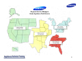
2008 Appliance Products
1
Table of Contents
PAGE
DESCRIPTION
3
17
87
97
161
316
329
Support Information
Refrigerator
Window Air Conditioner
Dishwasher
Laundry
OTR Microwave
Electric Range
2
Chapter 1
Samsung
Support Information
3
4
Support Contact Numbers
•
•
•
•
•
•
•
•
Customer Service
– 1-800-SAMSUNG (726-7864)
Authorized Service Centers Tech Assist
– 866-797-8736 (account number
required)
– Hours 9AM – 9PM Eastern Time
– 11AM - 4PM Eastern Time Saturdays
– Email
[email protected]
Non Authorized Service Centers
– 201-584-0412- Fax service Only
Warranty Assistance: 800-849-2198 option 8
Web Site Assistance: 1-201-229-4177
Web Site Assistance
[email protected]
Training Requests
[email protected]
Tech Talk Newsletter Subscriptions
[email protected]
• Global Service Partner Network
http://service.samsungportal.com
• Login and Password Issues: Elisa Pagliaro
[email protected]
• GSPN Content Issues: Jim Foster
[email protected]
Parts can be ordered through:
Samsung GPCA
Global Parts Center America
Parts ordering or backorders
800-634-8276
or you may use:
Marcone Appliance Parts
800-482-6022
5
Regional Service Managers
Home Appliance Field Service
6
Be Prepared When Calling for
Technical Assistance on Appliances
Slow Times: 6-9 PM EST M-F; 11-4 EST Sat.
For prescreening calls
The technical assistance team needs four things when you call:
•
•
•
•
Your account number
Product model number
Product serial number
Your name
Remove the service covers of the equipment under repair and
be prepared to take measurements and test components.
Please remember, Laundry and Refrigeration products have a
letter at the end of the serial number.
7
Ref & Laundry Serial Number Information
Model Name
Production Line
Check Digit
635543CP100160A
Pro. Year
Y : 2005
A : 2006 Jan
L : From 2006 Feb
P : 2007
Pro. Month
1~9 : Jan~Sep
A : October
B : November
C : December
Model Name
8
Refrigerator Model Number Nomenclature
• RS = Side by Side
• RF = French Door
• RM = Four Door
• RB = Bottom Mount Freezer
9
Technical assistance will not be able to help
unless you are properly prepared with tools when you are with the product.
• Multimeter requirements for appliance calls:
– Accurately measure DC voltage to the hundredths of a
volt (3.56VDC) from 1VDC to 24VDC with special meter
leads or safety pins to read voltages at the small
connectors on the main circuit board.
– Accurately read resistance from 1 Ω to 200K Ω
– Accurately read AC voltage from 16VAC to 240VAC
– Replacement meter batteries!!!!!!
• Please have an instrument available to accurately measure
freezer and refrigerator temperatures.
• An Amp Probe or Watt Meter would be an advantage.
10
Know your
meter scales
Use for Sensor
Voltage Tests or
20 VDC scale on
some meters
Use for Defrost
Heater tests
11
REDO Prevention Tips
Samsung Electronics is currently focusing on reducing our repeat
repairs (Redo). We have prepared the following tips for all of our
Service Centers to follow so that we can improve our overall
service to our mutual customers.
1. The technician should always talk directly to the customer before each call. Many techs get
their idea of what’s wrong via 2nd hand conversation, bring the wrong parts and put it in figuring
doing something is better than nothing. This is a bad practice.
2. Ask the customer if there were any other symptoms before the current problem appeared.
3. If you do not see the defect during your visit and you are not sure what the problem is, do not
guess on the repair. Confirm the symptom by picture, Technical support, or research on PVI
website.
4. Do not submit a claim using EADJ if no adjustments were actually performed because
this will contribute to a REDO if a 2nd call is needed. Be sure to properly code the repair.
See list of repair codes on the next page which do not affect the REDO rate.
5. If you are 99% sure that one of two possible parts will repair the unit, change both parts.
However, only do this when you are sure that this will repair the unit because one of our KPI is
amount of parts used.
6. Spend time after the repair burning the part in (at least 20 min) and talk to the customer to
make sure they are satisfied with the repair (not going to call back after you leave).
7. Please review your claim submission process to make sure that you are not submitting two
claims for the same unit repair at the same time.
These are some of the habits of the best technicians in the country. The best technicians also
concentrate on having the correct parts in stock by reviewing their weekly usage. If you have any
other tips which you have found to be successful in reducing repeat repairs, please send them to
your RSM.
12
Repair Codes Excluded from REDO calculation:
•
•
•
•
•
•
•
•
•
•
•
•
•
CEST: Customer Refuse Estimate
CLEA: Cleaning
CLEN: Cleaning
CUST: Customer Education
DTYX: Dirty
EXCP: EXCH-Company Policies
EXES: EXCH-Excessive Service
EXLW: EXCH-By law
FACT: Factory Modification
HOLD: Waiting for parts
INST: Installation
ISTL: Installation
MACC: Missing Accessory
Samsung will
pay the minor
warranty rate
for a customer
education call
ONE time for
each
consumer
product while
under
warranty
•
•
•
•
•
•
•
•
•
•
•
•
•
MISS: Missing
MMCH: Mis-Match
NPFD: No problem found
NPRB: No problem found
PANT: Paint
RCON: Reconnect
RECH: Recharge
RECO: Reconnect
RSTU: Reseat
SCHX: Scratch
SPEC: Specification
measurement
WSUP: Wrong Setup
RCLL: Recall
If a initial warranty claim is submitted with one of the above repair codes
and another repair is submitted within 90 days the service center is
NOT charged with a REDO
13
Quick Document Search
1. From the Main Menu Select “Warranty/Parts”
2. Type in the Model Number in the
Left Hand Search Field
HLP5063
3. Click on
the
Magnifier
Button
4. Manuals and
Bulletins are
displayed with
appropriate
hyperlinks
14
Parts List Search
To search for the Bill of Materials (BOM)
1. Click Warranty/Parts Tab
2. Order management -> Parts
Information -> Parts list by Model
3. Type in the Model Code and click
Search
15
Bill of Materials Search Tip
1. Click on the correct model code
(Check country list on right to make sure it is the right model)
2. Check mark the parts you need and Click CREAT P/O or ADD TO CART
3. Service bulletins and tips can be found for the specific part
16
Chapter 2
Refrigerator Technology
17
Dual Evaporator with TDM valve
The Time Divided Multi-cycle (TDM) System
(Stepper Valve) is used to switch refrigerant
flow in the 4 Door (RM25*) and French Door
(RFG29*). This improves temperature control
and energy efficiency.
Quad Cooling RM Model
Twin Cooling RS/RF/RB Models
18
Inverter Compressor
Inverter compressors offer energy savings not available in a
standard compressor
19
Refrigerant Path
Compressor
Sub-condenser
Hot Pipe
Dryer
Step valve
R Capillary Tube
R/CR Evaporator
F Capillary Tube
C/CF Evaporator
Suction Pipe
C Capillary Tube
Compressor
20
Chapter 3
Refrigerator Troubleshooting
21
Refrigeration Troubleshooting
• The Forced Operation Mode is a very valuable
troubleshooting tool for testing compressor operation, fan
operation and defrost operation.
• Forced Freeze Mode
• The compressor is started without the 5 minute delay
• You can check the compressor voltage at the main
PCB in this mode.
• You can accurately check defrost sensor voltages
in this mode
• All fans will be turned on in this mode, to allow voltage
testing. The door switches still control the fan
operation.
22
Refrigeration Troubleshooting
• Forced Freeze Mode Inverter Compressors
• The compressor is started without the 5 minute delay
• You can force the three speed options of this
compressor
• You can accurately check the temp and sensor
operation
• All fans will be turned on in this mode, to allow voltage
testing. The door switches still control the fan operation.
23
Refrigeration Troubleshooting
• Forced Defrost Operation
• Standard compressor models can activate the Fridge
defrost only, or both the Fridge and Freezer defrost.
• Inverter compressor models activate all heaters at once.
• In the Forced Defrost Mode the defrost sensor still
controls the heater operation. When defrost is activated
the main PCB will turn over defrost control to the sensor
in about 90 seconds. If the defrost sensor reads a
temperature above the shut off point it will tell the main
PCB to turn off the defrost voltage.
• Even when the defrost is turned off the unit will stay in
the forced mode for up to 24 hours.
24
Refrigeration Troubleshooting
• Selecting the Forced Modes
• When the two buttons are pressed together to enter the
Forced Modes you must wait for the beep and the
display to go blank. You then have 8 seconds to press
the Freeze button to activate the Forced Freeze Mode.
Once you are in this mode, press the Freeze button to
advance to the next function.
• Depending on the model, there are from two to four
Forced Modes. You must always wait for the beeping to
start before advancing to the next mode, if you wait
over 8 seconds to press the Freeze button, you will
have to start over again. If you lose track of where you
are in the Forced Modes, unplug the unit and start over.
25
Forced Operation and Test Mode
Test Mode
Press both buttons simultaneously for 8 seconds!
Display Code
FF
RD
FD
--
Function
Forced Compressor Run
Forced Refrigerator Defrost
Forced Freezer Defrost
Test Mode active
Press any button one more time
to cancellation Forced Mode
Cancellation
Forced
Forced
Operation
Operation
Press any button One time
at the Test Mode
Forced
ForcedDefrost
Defrost
for
forFridge
Fridge
Press any button One time
at the Forced Operation
Forced
ForcedDefrost
Defrost
for
forboth
both
compartment
compartment
Press any button one more time
at the Forced Defrost for Fridge
26
Forced Operation
For various refrigerator panels
Press both buttons simultaneously for 8 seconds!
Cancellation, unplug unit
Press Freezer button One time at the
Test Mode to Force Compressor
Forced
Forced
Compressor
Compressor
Wait 5 seconds between
button pushes
Press Freezer button Second
time for Forced Defrost of Fridge
Forced
ForcedDefrost
Defrost
for
forFridge
Fridge
Press Freezer button a
third time to Force
Defrost for Fridge &
Freezer
Forced
ForcedDefrost
Defrost
for
forboth
both
compartment
compartment
27
RFG29* Series Inverter Compressor Forced Mode
For Test Mode
Press both buttons simultaneously for ~15 seconds!
Press Freezer button One time at the Test
Mode to Force each Compressor test
Forced
Forced
Compressor
Compressor
High
High
Forced
Forced
Compressor
Compressor
Mid
Mid
3600 RPM
2450 RPM
Forced
Forced
Compressor
Compressor
Low
Low
Wait 5 seconds between
button presses
2050 RPM
Simultaneous manual defrost (fresh food and freezer compartments) function
Press Freezer button a 4th time to Force
Defrost for ALL Compartments
Forced
ForcedDefrost
Defrost
for
for ALL
ALL
compartments
compartments
28
RM257*** Series Inverter Compressor Forced Mode
For Test Mode
Press both buttons simultaneously for ~15 seconds!
Press Freezer button One time at the Test
Mode to Force each Compressor test
Forced
Forced
Compressor
Compressor
High
High
Forced
Forced
Compressor
Compressor
Low
Low
~ 3600 RPM
~ 2450 RPM
Forced
Forced
Compressor
Compressor
Mid
Mid
Wait 5 seconds between
button presses
~ 2050 RPM
Simultaneous manual defrost (all four compartments) function
Press Freezer button a 4th time to Force
Defrost for ALL Compartments
Forced
ForcedDefrost
Defrost
for
for ALL
ALL
compartments
compartments
29
Forced Mode for Single Evaporator units
Use Freezer Key as a Test Key
Wait 5 seconds between
button pushes
RS26/2530**
30
Refrigeration Troubleshooting
• The Diagnostic Mode is the most valuable troubleshooting tool
you have for troubleshooting a refrigerator. When you are at
the product this is the first test you should do.
• When a Samsung refrigerator is powered up if performs a Self
Diagnosis, if an open or shorted sensor is detected it will lock
the display and flash the code in the display. The refrigerator
may have no operation, or operate in the emergency mode.
Other faults detected will not lock the display or stop operation.
• To restart operation put into Manual Diagnostic Mode.
• Sensors that are off value, but not shorted or open, will not
bring up a fault code.
Note: accessing this function resets ALL programming and
error codes.
31
Refrigeration Troubleshooting
• To enter the manual Diagnostic Mode you must press and
hold two buttons, and hold them until the display stops
blinking and beeps.
• Fault code display for all models that have temperature
numbers in the display:
– Each 8 is made up of 7 segments, each
of those segments is a possible fault code.
• If there are no faults, the display will be blank or have all four
(8888) showing.
• On single evaporator units, no number display, lines or
symbols will light up for faults.
• On all models the display will come back to normal in about
12 seconds
32
Refrigeration Troubleshooting
• A Sample fault code would be
this is an example of
an Ice Maker Sensor failure.
• Things that can happen with this fault.
• After a power failure the unit would be “dead”, lights work
and blinking this code.
• The Ice Maker is not making any ice
• The Ice Maker is dumping partially frozen cubes
• If you see the fault below, ignore it. This is a modem
communication error not applicable in the US.
33
Self Diagnostics
Press both buttons simultaneously for 8 seconds
If a corresponding LED flickers, it means an
abnormality of a sensor or component.
34
Self Diagnosis
Hold Buttons until display stops blinking and beeps, then release and read
fault codes. Various refrigerator panels are shown
35
Error Code Display Pt 1
Error items for self-diagnostics
Codes are
shown for
example,
a full list
of codes
for the
specific
product is
available
in the
service
manual
NO
Error items
1
I/M-SENSOR
2
R-SENSOR
LED
TROUBLE
Ice maker sensor measures open or shorted
Refrigerator sensor measures open or shorted
DEFROSTING
3 SENSOR OF R
COMPARTMENT
Refrigerator Defrost Sensor measures open or shorted
4
Refrigerator fan motor stuck or spinning to fast
R-FAN ERROR
Temperature Sensors are Negative Temp. coefficient measuring between 2.2 K and 100K Ω
36
Error Code Display Pt 2
Error items for self-diagnostics
NO
Codes are
shown for
example,
a full list
of codes
for the
specific
product is
available
in the
service
manual
5
7
8
Error items
LED
TROUBLE
I/M FUNCTION
ERROR
Ice maker did not return to level after an ice harvest, this is
displayed after three attempts
R-DEFROSTING
ERROR
Refrigerator Compartment defrosting heater- electric wire cut,
short-circuit, contact failure, missing of sensor housing, or
defective temperature fuse/bi-metal. The defect is also displayed
if defrosting is not finished until after continuous heating over 80
minutes.
CR-SENSOR
CR Compartment Sensor Error- This can be an Electric wire cut,
short-circuit, contact failure, or missing sensor. This can also be
caused by a temperature reading > 122° or < -58 .
37
Error Code Display Pt 3
Error items for self-diagnostics
Codes are
shown for
example,
a full list
of codes
for the
specific
product is
available
in the
service
manual
LED
TROUBLE
NO
Error items
9
DEFROSTING
SENSOR OF CR
COMPARTMENT
CR compartment Defrost Sensor Error- This can be an Electric
wire cut, short-circuit, contact failure, or missing sensor. This can
also be caused by a temperature reading > 122° or < -58 .
10
DEFROSTING
SENSOR OF CF
COMPARTMENT
CF compartment Defrost Sensor Error- This can be an Electric
wire cut, short-circuit, contact failure, or missing sensor. This can
also be caused by a temperature reading > 122° or < -58 .
CR-DEFROSTING
ERROR
CR Compartment defrosting heater- electric wire cut, short-circuit,
contact failure, missing of sensor housing, or defective
temperature fuse/bi-metal. The defect is also displayed if
defrosting is not finished until after continuous heating over 80
minutes.
CF-DEFROSTING
ERROR
CR Compartment defrosting heater- electric wire cut, short-circuit,
contact failure, missing of sensor housing, or defective
temperature fuse/bi-metal. The defect is also displayed if
defrosting is not finished until after continuous heating over 80
minutes.
11
12
38
Error Code Display Pt 4
Error items for self-diagnostics
Codes
are
shown
for
example,
a full list
of codes
for the
specific
product
is
available
in the
service
manual
NO
Error items
13
WATER HEATER
ERROR
14
EXT-SENSOR
15
F-SENSOR
16
F-DEF-SENSOR
LED
TROUBLE
Water Reservoir Heater measures open
Ambient Temperature Sensor reads open or shorted
Freezer Temperature Sensor reads open or shorted
Freezer compartment Defrost Sensor Error- This can be an Electric
wire cut, short-circuit, contact failure, or missing sensor. This can
also be caused by a temperature reading > 122° or < -58 .
39
Error Code Display Pt 5
Error items for self-diagnostics
NO
Codes
are
shown
for
example,
a full list
of codes
for the
specific
product
is
available
in the
service
manual
Error items
LED
TROUBLE
Freezer fan motor stuck or spinning to fast
17
F-FAN ERROR
18
C-FAN ERROR
19
CF-SENSOR
CF Compartment Temperature Sensor reads open or shorted
F-DEFROSTING
ERROR
Freezer Compartment defrosting heater- electric wire cut, shortcircuit, contact failure, missing of sensor housing, or defective
temperature fuse/bi-metal. The defect is also displayed if
defrosting is not finished until after continuous heating over 80
minutes.
20
Compressor fan motor stuck or spinning to fast
40
Error Code Display Pt 6
Error items for self-diagnostics
Codes
are
shown
for
example,
a full list
of codes
for the
specific
product
is
available
in the
service
manual
NO
Error items
21
CF-FAN ERROR
22
CR-FAN ERROR
24
ICE PIPE HEATER
ERROR
LED
TROUBLE
CF Compartment fan motor stuck or spinning to fast
CR Compartment fan motor stuck or spinning to fast
Ice Maker Fill line heater measures open
41
Error Code Display Pt 7
Error items for self-diagnostics
Codes
are
shown
for
example,
a full list
of codes
for the
specific
product
is
available
in the
service
manual
NO
Error items
25
Uart
COMMUNICATION
ERROR
26
27
L↔M
COMMUNICATION
ERROR
P↔M
COMMUNICATION
ERROR
LED
TROUBLE
This error is not applicable if you encounter this error during
diagnostics ignore it
Bad communication between LOAD↔MAIN MICOM
Bad communication between LCD Panel ↔MAIN MICOM
42
2008 French Door Refrigerator Error Codes
Codes
are
shown
for
example,
a full list
of codes
for the
specific
product
is
available
in the
service
manual
43
2008 French Door Refrigerator Error Codes
Codes
are
shown
for
example,
a full list
of codes
for the
specific
product
is
available
in the
service
manual
44
Defrosting Troubleshooting
Check for any fault codes in the manual Diagnostic Mode
Frozen Evaporator
YES
Ask the Consumer if there has been water or ice build up
on the bottom of the Fridge compartment or the floor.
Check for frozen drain
and/or open drain heater
NO
Frozen Evaporator
YES
Is the Defrost Heater Open?
Replace heating element
or evaporator
NO
Frozen Evaporator
Is the Door gasket or door flap leaking?
YES
Replace door gaskets
NO
Frozen Evaporator
Check for cracks in liner or air leaks
45
Testing Defrost Circuits
Access the main PCB for voltage/resistance testing
–
–
–
–
With the compressor running test the sensors
Enter Forced Mode Defrost
Measure the heater voltage
Remove the power and heater connector and check the
heater circuit resistance
• Defrost Sensor
– The sensor shuts off heater At 50 in Freezer, 63 in Fridge
– If the sensor is bad it may shut off the defrost circuit in a few
minutes or not start, causing ice build-up, or it could lock up
in defrost mode and become a total no cool.
Note: A defective sensor may check OK at room temperature, test
at operating temperature only.
46
Defrosting Troubleshooting Part 1
• Defrost Sensors
– Testing: Check the DC voltage across both evaporator
defrost sensors, with the compressor running. They
should read less than a tenth of a volt difference, as they
are both on the same refrigerant line. They usually read
~ 3.7VDC, after the compressor has been running for
about 10 minutes. You may find one reading about 30 to
50 degrees off (lower VDC - higher temp), if so replace it.
• Alternate Sensor Testing
Make ice slurry. To do this, fill a cup with ice (preferably
crushed), then add water and a teaspoon of salt to make a
slush. Mix thoroughly and allow to sit for 2 to 3 minutes. This
will give you a 32 reference. Lower the sensor into the mixture
and leave for about 1 minute, check the resistance. It should
be very close to 13,300 Ω. Before reinstalling the sensor, be
sure to rinse it with fresh water and dry it.
47
Defrosting Troubleshooting Part 2
Enter the Forced Mode per instructions
• Check heater circuit amperage at the Main PCB or A/C line;
look for ~1.2 amps for the Fridge and ~2.2 amps for the freezer or
3.4 amps total.
NOTE: If compartment is warm, you only have about 90 seconds
to test.
• Freezer - Check service manual for connector and wire color
code for the model being serviced.
• Fridge - Check service manual for connector and wire color code
for the model being serviced.
• Low Current draw? Check individual defrost circuits, if one is low
check for open defrost heater
• No Current draw? Check voltages and resistances next.
48
Defrosting Troubleshooting Part 3
Enter the Forced Mode per instructions
• Check the heater circuit voltage at the Main PCB; should be
120VAC for Freezer and Fridge.
NOTE: If compartment is warm, you only have about 90 seconds to
test.
Listen for the relay closing then check the heaters.
• Freezer Defrost Heater - Check service manual for connector and
wire color code for the model being serviced.
• Fridge Defrost Heater - Check service manual for connector and
wire color code for the model being serviced.
• No AC Voltage? Change Main PCB
49
Defrosting Troubleshooting Part 4
Heater circuit resistance - Unplug the refrigerator. Remove
the defrost heater connector from PCB.
• Freezer - Check heater circuit resistance at the Main PCB,
look for 35–50 Ω average.
• Fridge - Check heater circuit resistance at the Main PCB,
look for 60-95 Ω average.
• Freezer & Fridge - If resistance is around 2600 Ω, ThermoFuse (Bi-metal) is good, Defrost heater is open.
• Open Circuit - Check the Thermal Fuse (Bi-metal), Heater
and Connectors
50
Defrosting Troubleshooting
Example of a
2600 Ω heater
51
Defrost Error Symptoms
NOTE: Evaporator covers may break if removed while
frozen as they are plastic, replace if damaged.
• Ice build up in either the freezer or refrigerator compartment
can be caused by a blocked drain. It is possible that the drain
is not being defrosted by the heaters enough to properly clear
the drain and pass the melted water into the catch pan.
• Noise from the refrigerator/freezer fan or weak cooling.
Noise disappears when the customer opens door.
The defrost sensor, heater, thermal fuse/bimetal device are
OK but ice is built up in the drain area of evaporator cover.
52
Defrosting Error Causes
• The heat from the defrost heater does not transfer to the
evaporator drain
• The Styrofoam around the evaporator cover absorbs moisture
and frost begins to form on the evaporator, defective evaporator
cover.
• During the defrost cycle, the frost melts and drips down to the
drain where it becomes frozen again.
• Ice blockage in the drain grows larger with every defrost cycle.
• Because of the growing ice block, cooling efficiency diminishes
at a growing rate and eventually blocks the fan blades.
• Self diagnostics will eventually show a fan error.
53
Defrost Circuit Modification
•
Metal clips “A” and “C” can be placed on both the evaporator cover and the
evaporator. The metal clips will touch and transfer heat more efficiently from the
defrost heaters to the drain preventing ice build up.
Part numbers for these parts are as follows:
A: DA61-03502A PLATE-DRAIN INS EVAP, REF
C: DA61-03585A FIXER-EVAP REF
54
Compressor Controller board connector
arrangement and detail explanation (RM257AB*)
Forced Modes:
12VDC
5VDC
Ground
Compressor RPM
FF1 - Compressor high speed
- 2.7 amps
FF2 - Compressor low speed
- 1.6 amps
FF3 - Compressor medium speed - 2.0 amps
FD - All defrost elements on
- ~ 4.0 amps
NOTE: FF2 & FF3 could be reversed.
Compressor not running
Check for 5 minute delay
-- Not in delay
Force Operation
-- If no operation, disconnect CN03 (SMPS PCB) and check resistance to
the windings. ~10 Ω
Comp windings OK
-- Disconnect CN02 (SMPS PCB), check resistance to overload
Overload OK
-- Replace Main PCB and Inverter PCB
Compressor
OLP
55
Model: RFG294 **, RFG295**, RFG299**
Compressor Troubleshooting
CN04
VDD
VSS
RPM
FB
CN01 POWER(115VAC)
CN03
U
V
W
CN02 OLP
Compressor not running
Forced Modes:
Check for 5 minute delay -- Not in delay
FF1 - Compressor high speed
- 2.7 amps
Force Operation
FF2 - Compressor medium speed - 2.0 amps
If no operation, disconnect CN03 (SMPS PCB) and check FF3 - Compressor low speed
- 1.6 amps
resistance to the windings. ~ 10 Ω
FD - All defrost elements on
- ~ 3.4 amps
Comp windings OK
Disconnect CN02 (SMPS PCB), check resistance to overload
Overload OK
Replace Main PCB and SMPS PCB
56
Chapter 4
Common Refrigerator Service Issues
57
No Ice - Flex Tray I/M
•
•
•
•
•
For the ice maker to operate properly, water pressure between 20 and 125 PSI is
required. A quick test of water pressure would be filling a 6 Oz paper cup in less
than 10 seconds. If the internal water filter is clogged, the water pressure to the
icemaker will be reduced. The foreign matter at the water supply valve near the
icemaker can also reduce the water pressure. Additionally, low water pressure at
the fill tube can be caused by a defective fill tube heater.
If the tray seems to be filling completely but the unit never harvests, verify the
operation of the Icemaker sensor in the tray. Normally the unit harvests when the
sensor reads approximately 1.5
for 5 minutes. The sensor should read about
3.7VDC at the main board connector when the cube temperature is 1.5 . After
the fill, the sensor will read water temp, 1.5 to 2.2VDC. Remember, using frame
ground might produce inaccurate values; instead use the DC ground on the PC
board. If this value is incorrect the sensor is suspected to be defective.
You can also verify the operation of the harvest motor by pressing the black test
unit on the motor housing near the back of the assembly.
Is the freezer not dropping below 10 ?
Make sure the Freezer defrost circuit is working properly and the evaporator and
condenser fans are working correctly. Inspect condenser coil for air blockage.
58
Slow Ice - Flex Tray I/M
•
•
•
•
This problem is usually caused by a defective sensor or low water pressure. The I/M
sensor will delay the time by adding extra fills if the water pressure is low. Also check
the operation of the freezer, if the freezer temperature is above 1.5 , ice production
will be delayed. This can also be caused by a problem with the freezer air vent, make
sure the air duct near the ice maker is not restricted. If the unit is on an R/O water
system, water pressure may be to low for consistent ice production.
Is there any frost in the freezer compartment?
Excessive frost could mean warm air leaking into the compartment warming the top
of the freezer preventing the ice maker sensor from maintaining the necessary 1.5
to harvest.
• Check for ice chute failure, a leak at ice maker fill tube, an air leak around
defrost water drain by evaporator coil, cracks in liner or a bad door seal.
Finally make sure the most updated version of Ice maker kit has been installed. The
ice maker designs in many models have been updated for better performance. Check
GSPN for any related service bulletins regarding Ice-maker changes.
59
Shattered Ice Cubes - Flex Tray I/M
•
•
•
•
•
•
When all ice shatters it's because of a bad tray or harvesting at a temp that is too
cold (lower than 1.5 ), in some areas hard water issues that can also cause
shattered cubes. The temp in the freezer should not have any effect on this issue, as
long as it’s below 1.5 , as a properly installed sensor will not read the freezer temp,
only the water/ice temp.
Check the Ice tray for defects in the plastic. Impurities or hard water can cause the
plastic to become rough and inhibit the ice falling from the tray during the twisting. If
this is the case, replace the tray assembly.
It is possible to get ice too cold. Ice that is too cold will shatter during harvest. This
can be from the (1) sensor not reading the correct temp (2) the sensor not mounted
correctly (3) by programming the icemaker offset value to a lower number (4) the
board not understanding the reading.
To check the sensor you must check the tray temp (not air temp) and compare it to
the sensor reading. The sensor should read about 3.7VDC at the main board
connector when the cube temperature is 5 degrees. After the fill the sensor will read
water temp 1.5 to 2.2VDC.
To clear offsets, put unit into Diagnostics mode.
Please note, some shattering is normal for a flex tray icemaker, especially if the Ice
Off feature was used recently.
60
Service ConcernsHeat Release I/M
•
•
•
•
Troubleshooting Observations
Is there any frost in the freezer compartment?
Excessive frost on the evaporator coil will either coat the coil enough to
warm the air to 32 to supply the ice room or block the air duct
completely to the ice room. Make sure the Freezer defrost circuit is
working properly and the freezer and ice room compartments are sealed
properly
The consumer complaint could be “it only makes ice once or twice a day”
The Ice maker will harvest within a few hours of the freezer defrost cycle,
when the evaporator is frost free. As the frost builds up on the
evaporator again the ice maker will stop as the temperature is too warm.
Ice making will stop until the next defrost cycle completes which will be
12 to 23 hours later. This is a defrost error not an icemaker error. Check
the freezer door seal, ice room door seal and the freezer defrost heater.
61
Service Concerns –
Heat Release I/M
• Is the Ice Bucket locked firmly in position?
• Try to move the bucket, when locked in place, any movement
would mean that one of the locks is not latched. This will cause
warm fridge air to enter the ice room and stop ice production.
• Temperature checks (Actual)
• The Back of Ice Room should measure 0 to 6 when making ice
• The Back of Freezer compartment should measure -4 to +3
62
Heat Release Ice Maker - Troubleshooting
• Voltage tests
• The Ice Room Sensor voltage should match the actual
ice room temperature; refer to the sensor voltage/
temperature chart in the service manual.
• The Freezer Sensor voltage should match the freezer
temperature and also be close to the actual ice room
temperature, refer to the sensor voltage/ temperature
chart in the service manual. If the bucket is full the Ice
Room temperature should be around 24
.
63
Heat Release Ice Maker - Troubleshooting
• The Freezer Defrost Sensor Voltage should be 0 to -17 ,
with the compressor running, to show no frost/ice buildup
and good operating system, refer to the sensor
voltage/temperature chart in the service manual.
• The Ejecting Thermistor should not measure below 17 ,
unless the bucket is full, as it should harvest at 18 . If
Ejecting Thermistor measures actual ice room
temperature, and the bucket is not full, it would mean that
the I/M is not harvesting. If there has been a recent
harvest, the thermistor might measure up to 50
as the
mold heater and fresh water has warmed the sensor.
64
Heat Release Ice Maker - Troubleshooting
• If any of the sensors measure incorrectly replace the defective
sensor
• The Ice Room Fan should read around 7 to 9 VDC when it is
running. Be sure to defeat the door open switch when testing
the fans. You can force the fan to turn on by putting the unit
into the Forced Freeze mode.
• If the I/M Thermistor reads below 18 after 38 minutes and
there is no harvest replace the main PCB
65
RF267**, RF26VAB** Not all Connectors and pins used on all models
CN73 A/C Load
1-(CN70-1) Cube Solenoid (Yel/Red) RF267
3-(CN70-1) Auger Motor (Pink/Red) RF267
5-(CN70-1) Dispenser Valve (W/Blk-Red) RF267,266
7-(CN70-1) Ice Maker Valve (Vio/Red)
9-(CN70-1) Ice Cover Route (Brown/Red) RF267
CN71
1-(CN70-1) R Lamps (Blue/Red)
3-(CN70-1) F Lamp (Vio/Red)
5 Common N (Gray)
7-(CN70-1) Comp (SkyBlue/Red)
9 Heater Common (Org)
CN70
1 Common Line L (Red)
3-(CN71-5) Disp Heater (Black/Gray) (RF267)
5-(CN71-5) French Heater (Yel/Gray)
7-(CN71-9) R Defrost (White/Orange)
9-(CN71-9) F Defrost (Brown/Orange)
CN72 (RF267 only)
1-(CN70-1)Ice Maker Motor (Brn)
3-(CN70-1)Ice Maker Heater (Wht)
CN91 Pantry Room Damper
1-2 Damper Heater 12VDC (Blk/Brn)
3-4 Damper Motor (White/Blue)
5-6 Damper Motor (Yel/Red)
CN10 Low Volt Power
1-3 5VDC (Red/Black)
5-3 12VDC (Yel/Black)
CN90 Ice Maker (RF267 only)
4-8 Eject Sensor (White/SkyBlu)
5-8 Test Switch 5VDC (Gry/SkyBlue)
6 Full Switch (Blue)
7 Horizontal Switch (Violet)
8 Ground (Sky/Blue)
CN78
4-5 Water Tank Heater (Brn/Blk) RF267
6,7,8 Pantry Display
9-11 +12vdc (Blue/White)
10-11 +5vdc Switch input (Vio/White)
CN50 Display
4-6 +12 VDC (Org/Pink)
5-6 +5 VDC (Yel/Pink)
8-(CN75-1) Water Switch (Blue/Red) RF266
CN30 Sensors & Switches
1-5 Freezer Dr Switch (Black/Gray)
2-(CN50-7) R Door Switch (Vio/Gray)
3- (CN75-1) F Sensor (Red/Gray)
4-(CN75-1) F Def Sensor (Org/Gray)
6-(CN75-1) R Sensor (White/Gray)
7-(CN75-1) R Def Sensor (SkyBlu-Gry)
8-9 Pantry Sensor (W/Black-Gry)
CN75 F, R, C Fans
2-1 F Fan (Yel/Gray)
3-1 R Fan (Org/Gray)
4-1 C Fan (S/Blu-Gry)
5 F Fan FG (Black)
6 R Fan FG (Brown)
7 C Fan FG (Red)
CN32 Sensor
1-4 Ambient Sensor (White/White)
2-(CN75-1) 5VDC to I/M (Red/Gray) RF267
3-(CN75-1) Ice Room Sensor (Org/Gray) RF267
CN76 Ice Room (RF267 only)
1-(CN75-1) Ice Room Fan (Black/Gray)
2 Ice Fan FG (Brown)
3-(CN75-1) Ice Bucket Switch (Red/Gray)
66
Model : RFG 294 **, RFG295**, RFG299** Not all Connectors and pins used on all models
CN74 A/C Load
1-(CN70-9) Cube Solenoid (Yel/Red)
3-(CN70-9) Auger Motor (Pink/Red)
5-(CN70-9) Dispenser Valve (W/Blk-Red)
7-(CN70-9) Ice Maker Valve (Vio/Red)
9-(CN70-9) Ice Cover Route (Blue/Red)
CN71
1-(CN70-9) R Lamps (Blue/Red)
3-(CN70-9) F Lamp (Violet/Red)
9 Heater Common (Orange)
CN73
1-(CN70-9) I/M Heater (Brn/Red)
3-(CN70-9) I/M Motor (Wht/Red)
CN76 F, R, C Fans
2-1 Ice Room Fan (Blk/Gry)
3-1 F Fan (Yellow/Gray)
4-1 R Fan (Orange/Gray)
5 C Fan (SkyBlue/Gray)
6 Ice Room Fan FG (Pink)
7 F Fan FG (Brown)
8 R Fan FG (Red)
9 C Fan FG (Blue)
CN31 Sensor
1-4 Ambient Sensor (White/White)
2-(CN90-8) 5VDC to I/M (Red/SkyBlu)
3-(CN76-1) Ice Room Sensor (Org/Gray)
CN78 Lamp/Veg LED
4-7 +13VDC (Red/Gray)
CN77 Stepper Motor
1 +13VDC (Red)
CN30 Sensors & Switches
1-5 Freezer Dr Switch (Black/Gray)
2-(CN50-7) R Door Switch (Vio/Gray)
3-(CN76-1) F Sensor (Red/Gray)
4-(CN76-1) F Def Sensor (Org/Gray)
6-(CN76-1) R Sensor (White/Gray)
8-(CN76-1) R Def Sensor (SkyBlu/Gry)
9-(CN76-1) Pantry Sensor (W/Blk-Gry)
CN91 Pantry Room Damper
1-2 Damper Heater 12VDC (Blk/Brn)
3-4 Damper Motor (White/Blue)
5-6 Damper Motor (Yel/Red)
CN90 Ice Maker
4-8 Eject Sensor (White/SkyBlu)
5-8 Test Switch 5VDC (Gry/SkyBlu)
6 Full Switch (Blue)
7 Horizontal Switch (Violet)
8 Ground (Sky Blue)
CN70
1-11 Disp Heater (Black/Gray)
3-11 French Heater (Yel/Gray)
5- (CN71-9) R Defrost (Wht/Org)
7- (CN71-9) F Defrost (Brn/Org)
9- L1 (Red)
10- N (Gray)
CN51 Pantry Room
7-5 +13VDC (Blue/White)
CN75
To Comp Inverter Board
CN50 Display
4-6 +13 VDC (Orange/Pink)
5-6 +5 VDC (Yellow/Pink)
8-6 Ice/Water Switch (Blue/Pink)
9-6 Ice Rte Switch 1 (Vio/Gray)
10-6 Ice Rte Switch 2 (White/Gray)
CN79
1-2 Photosynthesis Module (Blk/Brn)
10-6 Water Tank Heater (White/Pink)
67
Common Defrost Problems
Evaporator frozen, solid ice
• Fridge
– Bad evaporator cover, open drain heater, add Fixer and
Plate, or blocked drain.
• Freezer
– Open drain heater, bad evaporator cover, add fixer and
plate, or blocked drain
Evaporator frozen, all frost
• Fridge or Freezer
– Bad defrost sensor, open thermal fuse, bad main PCB,
open defrost heater
• Ice Chute Flapper not Sealing properly
68
Defrost Service
Single Evaporator Models
•
Frost/Ice forming on the evaporator cover and blocking fan and air tunnel to
fridge.
– Install Repair Kit for Serial Number range: up to **42BL3***** Units
manufactured before April of 2006 For model RS2630
– Check for ice chute failure, leak at ice maker fill tube, air leak around
defrost water drain by evaporator coil, cracks in liner, or door seal on
fridge or freezer.
– Excessive door openings, doors left open for long periods, hot foods
put in fridge
Evaporator frozen, solid ice
•
Blocked drain
Evaporator frozen, all frost
•
Bad defrost sensor, open thermal fuse, bad main PCB, open defrost heater
69
No Cool Service Issues
Both Compartments
•
•
•
•
Unit locked in defrost mode
Compressor relay failure on main PCB
Failure of both defrost circuits
No sealed system charge
Fridge
•
•
•
Failure of defrost circuit
Evaporator fan failure
Door switch failure
Freezer
•
•
•
•
Failure of defrost circuit
Evaporator fan failure
Door switch failure
Low sealed system charge
70
Service Access
•
Disassembly of Quattro Cool Evaporator Covers, both access the same way
71
Chapter 5
Refrigerator Installation and Door Removal
For additional installation details see the accompanying 2008 Installation DVD
72
Water Connection
1
2
- Insert the plastic water pipe hose to the existing water
source and fix it with compression hardware. If there is no
existing icemaker water line consult a licensed plumber.
Connect Water Pipe Hose - Check if there is any water leakage at the
connection areas and if the hose is being kinked.
When there is water leaking, try connecting
again.
Secure the Water Pipe
Tube
- With a C/F clip, fix the water pipe hose to the
refrigerator wall.
Make sure that the water pipe hose is not kinked or
damaged when dressing the excess water pipe.
Example of Bad Installation
Coiled hose, no backup tube, water hose
touching the floor.
Example of Good Installation
No coiled hose, backup tube added, water
hose does not touch on the floor.
Dress the
Water Pipe
Tube
73
Refrigerator Filter Housing Damage
Always use the original Samsung filter when replacement is required at the six month interval. When aftermarket filters are used,
there is the possibility that the filter will leak causing the water to freeze if the refrigerator temperature is set too low. When the water
freezes there is the possibility that the filter housing will crack and start flowing water into the refrigerator compartment. When this
happens the housing must be replaced.
Coat the “O” rings here
Housing may crack and leak here
In order to put the filter in smoothly and to be able to remove it without forcing it, try coating the “O” rings with medical grade silicone.
Note: Replacement refrigerator water filters will no longer be considered a service item and will exclusively be handled by Samsung
sales and marketing groups.
74
Door Removal – French Door Model
1. With the door opened, remove the
Top Table cap with a Flat head
screwdriver, and close the door.
Remove the 3 screws holding
down the Top Table and remove
the Top Table .
Refrigerator
Door
2. Disconnect the electrical connector
above the upper right door hinge and
the 3 electrical connectors above
the upper left door hinge.
Disconnect the water tube by
pulling the tube fitting apart as
shown in the picture.
75
Door Removal – French Door Model
3. Remove the 3 hex head bolts found
attached to the upper left and right door
hinges with a Wrench (10mm).
With a Philips head screwdriver, remove the
ground screw found attached to the upper
left and right door hinges. Remove the upper
left and right door hinges .
Refrigerator
Door
4. Lift the door straight up to remove.
5. With a Philips head screwdriver, remove the
2 screws attached to the lower left and
right door hinges. With a Wrench (10mm),
remove the 2 hex head bolts attached to the
lower left and right door hinges. Remove
the lower left and right door hinge .
76
Door Removal – French Door Model
1. Pull the drawer open to full extension
2. Remove the tilting pocket by pulling the both
brackets upward at the same time.
Freezer
Door
3. Take out the lower basket
up from rail system
by lifting the basket
4. Remove a fixing pin and remove a shaft
pushing it to the right side with your hand.
by
5. Separate the rail from the rail cover by pushing
the hooks in on both sides of the rail. After
pushing the hooks in, remove the drawer by
pulling towards you with both hands.
77
Door Removal – Side by Side Model
Take off the Leg-Cover by Removing the 3 screws.
Separate the Water Line by pressing the coupler and
pulling the water tube away.
With the Door closed, remove the screw on the Upper
Hinge Cover.
Disconnect the wires by gently pulling the connectors
apart.
If necessary, remove the Reed S/W using a flat blade
screwdriver.
Remove the Earth screw and the 3 bolts as shown.
Remove the Upper Hinge and remove the wiring
harness from the hinge slot.
Remove the door from the lower hinge by lifting up the
door straight.
78
Door Removal – Bottom Mount Model
Hinge Cover
1. After removing the screw, disassemble the Upper Right
Hinge Cover with opening door.
Refrigerator
Door
2. Disconnect electric wire on the top of the refrigerator.
3. With the 7/16 inch wrench, remove the three bolts that
hold the top of the refrigerator.
79
Door Removal – Bottom Mount Model
4. Remove the screw that hold the ground wire.
Refrigerator
Door
5. Separate Hinge from electric wire and ground wire as
shown below.
6. Disassemble the fridge door by lifting it upward. Be
careful not to drop and scratch the fridge door.
80
Door Removal – Bottom Mount Model
Refrigerator
Door
7. Separate the Cap assembled on the Middle Hinge.
Middle Hinge
Freezer Door
1. After removing the screw and two bolts,
disassemble Middle Hinge.
81
Door Removal – Bottom Mount Model
2. Remove/Disassemble the Middle Hinge connected to
the Freezer.
Freezer Door
3. Disassemble the Freezer door by lifting it upward. Be
careful not to drop and scratch the Freezer door
4. Disassemble the Cap on the Low Hinge.
82
Chapter 6
Best Refrigerator Repair Practices
83
Refrigerator Truck Stock Recommendations
Part 1
•
The recommended truck stock items list updated bi- monthly please check the Tech
Talk Newsletter for the most updated listing
( ) = Stock Quantity
(4) DA47-10160H Bi-Metal to replace all Thermal Fuses
(1) DA67-00466B Water Filter Bypass Cap (used to verify filter operation)
(1) DA62-00914B Water Valve
(2) DA73-30102E Drier
(2) DA73-30102F Drier
(1) DA31-00010C (DA31-00015A, DA31-00015B, DA31-00015C, DA31-00010D,
DA31-00010F) Condenser Fan Blade
(1) MK183CL2U/E01 (MK183CL2U/E07) Compressor
Defrost Sensor Common Part Number
(4) DA32-00006W -- Defrost Sensor with longest wires
Note: Replacement refrigerator water filters will no longer be considered a service
item and will exclusively be handled by Samsung sales and marketing groups.
84
Refrigerator Truck Stock Recommendations
Part 2
•
The recommended truck stock items list updated bi- monthly please check the Tech
Talk Newsletter for the most updated listing
( ) = Stock Quantity
Motors
(1) DA31-00020E DC Evaporator Fan Motor
(1) DA31-00002V A/C Evaporator Fan Motor
(1) DA31-00020H DC Condenser Fan Motor
(1) DA31-00103A Condenser Fan Motor
Ice Makers with sensor
(1) DA97-00258E ASSY ICE MAKER
(1) DA97-00258C ASSY ICE MAKER
(1) DA59-00294A ASSY ICE MAKER
(1) DA97-00258J ASSY ICE MAKER
(1) DA97-05422A ASSY ICE MAKER All Heat Release
85
Sensor Test Chart
Temp. ( )
-43.6
-41.8
-40.0
-38.2
-36.4
-34.6
-32.8
-31.0
-29.2
-27.4
-25.6
-23.8
-22.0
-20.2
-18.4
16.6
-14.8
-13.0
-11.2
-9.40
-7.60
-5.80
-4.00
-2.20
-0.40
1.40
3.20
5.00
6.80
8.60
10.4
Resistance(
)
98.9
93.7
88.9
84.2
79.8
75.7
71.8
68.2
64.7
61.5
58.4
55.6
52.8
50.2
47.8
45.5
43.3
41.2
39.2
37.4
35.7
34.0
32.4
30.9
29.5
28.1
26.9
25.7
24.5
23.4
22.4
Voltage
Resistance
(V)
Temp. ( )
( )
4.54
4.52
4.49
4.47
4.44
4.42
4.39
4.36
4.33
4.30
4.27
4.24
4.20
4.17
4.13
4.10
4.06
4.02
3.99
3.95
3.91
3.86
3.82
3.78
3.73
3.69
3.64
3.60
3.55
3.50
3.46
12.2
14.0
15.8
17.6
19.4
21.2
23.0
24.8
26.6
28.4
30.2
32.0
33.8
35.6
37.4
39.2
41.0
42.8
44.6
46.4
48.2
50.0
51.8
53.6
55.4
57.2
59.0
60.8
62.6
64.4
66.2
21.4
20.5
19.6
18.7
17.9
17.2
16.4
15.7
15.1
14.5
13.9
13.3
12.7
12.2
11.7
11.3
10.8
10.4
10.0
9.60
9.20
8.80
8.50
8.20
7.90
7.60
7.30
7.00
6.70
6.50
6.20
Table A
Voltage
(V)
Temp.
( )
Resistance
( )
Voltage
(V)
3.41
3.36
3.31
3.26
3.21
3.16
3.11
3.06
3.01
2.96
2.90
2.85
2.80
2.75
2.70
2.65
2.60
2.55
2.50
2.45
2.40
2.35
2.30
2.25
2.20
2.15
2.10
2.06
2.01
1.97
1.92
68.0
69.8
71.6
73.4
75.2
77.0
78.8
80.6
82.4
84.2
86.0
87.8
89.6
91.4
93.2
95.0
96.8
98.6
100.4
102.2
104.0
105.8
107.6
109.4
111.2
113.0
114.8
116.6
118.4
120.2
6.01
5.79
5.58
5.38
5.19
5.00
4.82
4.65
4.49
4.33
4.18
4.03
3.89
3.76
3.63
3.51
3.39
3.28
3.17
3.06
2.96
2.86
2.77
2.68
2.59
2.51
2.43
2.35
2.28
2.21
1.88
1.83
1.79
1.75
1.71
1.67
1.63
1.59
1.55
1.51
1.47
1.44
1.40
1.37
1.33
1.30
1.27
1.23
1.20
1.17
1.14
1.11
1.09
1.06
1.03
1.00
0.98
0.95
0.93
0.90
86