1
Installation
30-Inch
Dishwasher
For use with models: ED30 and ID30
Part No. 65538
Rev. H
Instructions
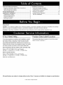
Important Safety Instructions ..........................................
Important Information About Safety Instructions ..............
Safety Symbols and Labels .............................................
General Safety Precautions .............................................
Product Specifications
.....................................................
Preparing for Installation ..................................................
Preparing the Location .....................................................
Electrical Specifications ...................................................
Install the Plumbing ..........................................................
Planning the Drain ...........................................................
1
1
1
2
3
4
4
5
5
5
Installation Instructions ....................................................
6
Verify the Package Contents ............................................
6
Installing the Unit in the Cabinet ...................................... 7
Cabinet Panel Installation ................................................
9
Plumbing Connections ...................................................
10
Verifying Proper Operation ..............................................
11
Toe Kick Installation .......................................................
12
Important:
Installer: In the interest of safety and to minimize problems, read these installation instructions completely and carefully
before you begin the installation process. Leave these installation instructions with the customer.
Customer:
Keep these installation instructions for future reference and the local electrical inspector's use.
If You Need Help...
Product Data Label Location
If you have questions or problems with installation, contact
your Dacor dealer or the Dacor Customer Service Team.
For repairs to Dacor appliances under warranty call the
Dacor Distinctive Service line. Whenever you call, have the
model and serial number of the appliance ready. The model
and serial number are printed on the product data label.
The product data label is located on the left door jamb.
Open the door to expose it.
Dacor Distinctive Service (repairs under warranty only)
Phone: (877) 337-3226 (U.S.A. and Canada)
Monday -- Friday 6:00 A.M.to 4:00 P.M.Pacific Time
Dacor Customer Service
Phone: (800) 793-0093 (U.S.A. and Canada)
Monday -- Friday 6:00 A.M.to 5:00 P.M.Pacific Time
Web site: www.Dacor.com
All specifications
are subject to change without notice. Dacor ®assumes no liability for changes to specifications.
© 2007 Dacor, all rights reserved.
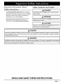
Important Information About
Safety Instructions
Safety Symbols and Labels
The Important Safety Instructions and warnings in
these instructions are not meant to cover all possible
problems and conditions that can occur. Use common
sense and caution when installing, maintaining or
operating this or any other appliance.
•
Always contact the Dacor Customer Service Team
about problems and conditions that you don't
understand. See Customer Service Information.
Immediate hazards that WILL result in severe personal
injury Or deathl
WARNING
Hazards Or Unsafe practices that COULD result in severe
personal injury or death.
I
[_ CAUTION
Hazards 0r Unsafe practices that COULD result in min0r
personal injury or property damage:
I
[_ WARNING
A qualified technician must complete the installation of this built.in appliance. The owner is responsible tO make sure the
dishwasher is properly installed. Improper c0nnecti0n Of the electrical Wiring may create an electric Shock Or fire hazard
and maY result in damage t0the dishwasheris electrical sYsteml
II
I
I
READ AND SAVE THESE INSTRUCTIONS
_mCD_
1
General Safety Precautions
To reduce the risk of fire, electric shock, serious injury or death when using your appliance, follow basic safety
precautions, including the following:
WARNING
Do not install or operate this dishwasher if it has
been damaged, dropped, has damaged electrical
conduit 0r wires or is not working properly. If the
product s damaged when received, immed ately
contact the dea eror builder.
,
Use this d shwasher only for its intended PUrpose
as outlined in the use and care manual. It is not
,
Keep all Packaging materials away from children
WARNING
•
Do not operate the dishwasher without the door
completely closed and the toe kick panel in place.
•
Store all detergents and rinse aids out of the reach of
children.
•
During loading, insert all sharp or pointed objects
with the handles up. Locate these items where they
will not damage the door seal or cause personal
injury.
•
Do not tamper with the controls.
•
Under certain conditions hydrogen gas may be
produced in a hot water system that has not been
used for two weeks or more. Hydrogen gas is
explosive. If the hot water system has not been used
for a period of time, turn on all hot water faucets and
let the water flow for several minutes to release any
accumulated hydrogen gas. Do not smoke or use an
open flame during this process.
•
To prevent child entrapment, always remove the
door from an old dishwasher when remov ng it from
service.
•
To prevent household mold and mildew damage,
periodically check the inlet and drain hoses for leaks.
•
If the dishwasher outlet is connected to a garbage
disposal, make sure the disposal is completely empty
before running the dishwasher.
•
To avoid damage to the racks, do not let sharp edges
come into contact with them.
•
This appliance is designed for installation by more
than one person. To avoid personal injury, do not
attempt to move or lift the dishwasher without
assistance.
•
To prevent personal injury and damage to the unit
due to it tipping over, do not push down on the door
anytime it is open. To reduce the chance of tipping,
attach the anti-tip brackets to the cabinet before
operation.
'
To avoid electric shockl this diShwasher must be
insta led and grounded by a qualified installer in
a
completely enclosed ca b net according to these
installation instructionsl
• AI! installation work, plumbing connections and
electrical
Wiring must be performed in accordance
With all app icable codes and standardsl
•
;
Install 0r locate this appliance only in accordance
with these installation instructions.
The installer must show the cust0merthe location
the fuse box or CirCUit breaker panel and the
electrical outlet so that the customer knows Where
and how to disconnect or turnthe power off.
Before installing or servicing the dishwashefi
disconnect the unit!s power plug from the electrical
outlet or switch power off at the fuse box or circuit
breaker panel and lock the electrica panel door to
prevent power from being sw tched on accidenta!lyl
when the circuit breaker panel cannot be locked
securely fasten a prominent warning device, such as
a tag, t0 the electrical panel
;
2
DO not tamper With the controls;
•
Do not leave children alone or unattended n the area
where the dishwasher is in use. Never allow children
to sit or stand on an applianCel Do not let children
•
Never allow anyone, including children, to sit or stand
on any part of the dishwashe r. Stepping or sitting
on any part of it may result in tipping, damage and
serious injuryl
,
Many surfaces within the dishwasher achieve high
temperatures.
Do not touch surfaces or items inside
the dishwasher during or immediately after Usel
Exercise caution When opening the (Joorl Let hot air
and steam escape before looking or reaching inside.
_mC_
The customer should not install, repair or replace
any part of the dishwasher unless specifically
recommended in the literature accompanying it.
A qualified service technician should perform all
other service. Contact the nearest Dacor authorized
service representative for examination, repair or
adjustment.
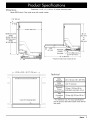
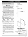
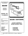
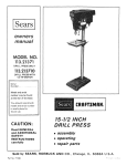
Dimensions
Tolerances: +1/16", -0, (+1.6 mm, -0) unless otherwise stated
Model ED30 shown. Door style varies with model number.
1 1/8" (29 mm)
23 3/4" (603 mm)*
_-
36 1/4"
ED30 Door panel
height
29 5/8" (752 mm)
ID30 Door panel
height
26 7/8" (683 mm)
(921 mm)
to
34"
(864 mm)
U
/4 mm/iusta ,o ,
toe-kick
front plate
,
_ED30
I
,,
"&-i
_-
_-129^J114,!_819_mm)l
o-
47" (1194 mm)*
* Allows for drain hose on back of unit
or ID30 - 29 7/8" (759 mm)_
Technical
I
)
{
I
Water
Pressure
Water
Temperature
Electrical
Circuit
Requirements
Total
Connected
Load
Cycle ON indicating lights
\
20 to 120 psi (138 - 827 kPa)
120 °F, minimum
15 Amp. 120 Vac, 60 Hz
dedicated, grounded, circuit.
12 Amp. @ 120 Vac, 60 Hz.**
** For reference only. For exact specifications
see the product data label located inside the left
door jamb.
_mCD_
3
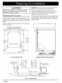
WARNING
observe all governing codes and ordinances during
planning and insta!lati0nl contact your 10calbuilding
I
department for further information.
I
IMPORTANT:shown
Followbelow
all cabinet
andsafe
countertop
dimensions
to insure
operation.minimum
I
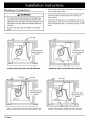
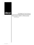
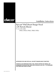
Prepare the installation location as shown below. All
minimum product dimensions be must met or exceeded
(see page 3). Dimensions shown provide minimum
clearances, unless otherwise noted.
Preparing the Location
Carefully check the location where the dishwasher is to be
installed. Put it in a location with convenient access. Make
certain that electrical power can be provided in the selected
location.
The floor must be solid, level and all cut-out surfaces must
be at right angles. The dishwasher must be secured to the
adjacent cabinets using the anti-tip brackets for safety and
proper operation.
Plan the installation so that the appliance can be removed
if service is required.
L
Anti-tip anchor into material under
countertop or adjacent cabinets
Min. countertop 25" (635 mm)
J
7"90°
90_
34"
24" Min. _
5"
(61
1"1
(127 mm)
b_/
(864 mm)
to
36 1/4"
(921 mm)
/
Utilities access hole
A
/
/
__
8" (203 ml l) I
I
ED or ID30 - 30" MJn.(762 ram)
CUT-OUT FRONT VIEW
CABINET INSTALLATION
Power cord
long
80" (2032 mm)
,
!
II II
dishwasher
Back of
54" (1372 mm)long
Water supply hose
U
u
%-_--2"
I
___t_
_--
(51 mm)
___
Drain line 48" (1219 mm)long
UTILITY CONNECTIONS
4
_mC_
SIDE VIEW
i
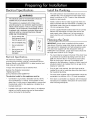
Electrical Specifications
Install the Plumbing
The water pressure must be between 20 and 120 psi
(138-827 kPa). The household hot water heater must
supply a minimum of 120 °F water to the dishwasher
location for best results.
WARNING
•
The electrical outlet for the dishwasher should be
installed only by a licensed electrician.
•
This appliance is equipped with a three prong
grounding plug for your protection against possible
electric shock hazards. If only a two prong outlet is
available, it is the customer-'s responsibility to have
it replaced with a dedicated, grounded three prong
electrical outlet by a licensed electrician. Do not
under any circumstances:
0
Cut or remove the
third (ground) prong
from the power cord.
0
Use an adapter plug.
0
Use an extension
cord.
0
Use a power cord
that is frayed or
damaged.
Install a valve for the hot water supply line where it is
easily accessible after the dishwasher is installed. The
dishwasher water inlet hose is equipped with a 3/8"
(10 mm) compression fitting.
•
Use the supplied flexible braided water line to connect
between the dishwasher hot water inlet and the hot
water supply valve. Make sure it is long enough to
reach when the unit is removed from the cabinet for
repair.
Planning the Drain
®
IMPORTANT: A drain hose is supplied with the product
(see above). Should a longer drain hose be required, use a
hose approved for detergents and high temperature water.
The drain hose supplied with the dishwasher meets an
AHAM DW-1 test standard. Longer drain hoses should not
be longer than a total of 12 ft. in length.
You must install an air gap in the drain if the drain hose
is connected to household plumbing lower than 20 in.
(508 mm) from the floor or if required by local codes.
Plan for the air gap in the sink or countertop area
adjacent to the dishwasher. A section of drain hose (not
provided) needs to be installed from the air gap to the
disposal or waste tee.
Electrical Specifications
The electrical installation, including minimum supply
wire size and grounding, must be Jn accordance with the
National Electric code ANSI/NFPA* (or latest revision) and
local codes and ordinances.
*A copy of this standard may be obtained from:
National Fire Protection Association
1 Batterymarch Park
Quincy, Massachusetts 02269-9101
•
If an air gap is not required, the drain hose must be
installed to an inlet or waste tee above the drain trap in
the household plumbing.
•
The drain hose supplied with the dishwasher should be
connected to a minimum 1/2 in. I.D. drain connection.
•
If the drain is connected to a disposal, see the disposal
manufacturer's installation instructions for correct drain
hose mounting techniques.
The electrical outlet for this appliance must be:
•
Connected to a grounded, dedicated 120 Vac, 60 Hz
circuit protected by a 15 Amp. circuit breaker or time
delay fuse. It is the owner's responsibility to ensure that
the electrical outlet for this appliance is installed by a
licensed electrician.
•
Located to the right or left of the cutout, in an adjacent
cabinet, so that the power plug can be disconnected
without removing the dishwasher.
_mCD_
5
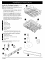
Verify the Package Contents
NOTE: Model ID30 ships without a front panel. It is
designed for the installation of an integrated front panel that
matches the surrounding cabinets.
•
With the assistance of at least one person, remove the
dishwasher from the shipping carton. Place the unit to
the side of the cabinet opening.
Remove all of the packing materials from inside and
outside of the unit. DO NOT allow any of the shipping
materials, loose screws or plastic to remain inside.
Remove the racks. Set them aside for later installation.
•
Unpack the parts box and verify that all required
components have been provided. If any item is missing
or damaged, please contact the dealer immediately. Do
not install a damaged or incomplete appliance.
D
Top rack
D
Bottom rack
I1_
Silverware basket
m_
Large particle filter
m_
small particle filter
m_
Medium particle filter
I[_
Product literature
Toe kick
A bottle of Dacor _ Stainless Steel Cleaner is also
included with models having stainless steel doors.
Additional tools/materials
required for installation:
Crescent wrench
I1_
Phillips head screwdriver
m_
Hose clamp (for 1 3/8" Dia. drain hose)
D
Tape measure
D
Level
Make sure you have everything necessary for proper
installation before proceeding.
E!
Ii
Ig
6
_mC_
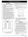
WARNING
Installing the Unit in the Cabinet
•
Do not connect the electrical, water inlet or drain
until instructed to do so in the Verifying Proper
Operation section.
•
Do not install the dishwasher unless the
.
electrical service provided meets the Electrical
Specifications.
.
Care should be exercised when the appliance is installed or
removed, to reduce the likelihood of damage to the power
cord or hoses.
A qualified technician must complete the installation
of this built-in appliance. The owner is responsible to
make sure the dishwasher is properly installed.
•
With the assistance of at least one person, set the unit
in front of the cut-out opening.
Feed the electrical cord, drain hose and water supply
hose through the utility access hole(s) in the side(s) of
the cabinet.
To avoid an electrical shock hazard make su re
the dishwasher power plug is disconnected before
proceeding with the installation.
Do not allow any material, including the hoses or
electrical wiring to be directly behind the dishwasher
while pushing it into the cut-out opening. Carefully
pull the slack out of both hoses and the wire from
utside the cut-out during push back to prevent
pinching. An electric shock hazard or water damage
may result from pinched wires or hoses. Damage due
to improper installation is not covered under warranty.
Utility cutouts
/
\
Hoses and
power cord
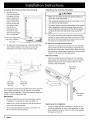
Keep the factory installed high loop drain hose in
place to ensure proper dishwasher operation. Do not
cut, tie, strap or lower it. If it is necessary to lengthen
it, install an aftermarket drain extension kit, available
at most home improvement stores.
.
Drain hose
Slide the dishwasher back into the opening while
pulling the hoses and electric cord through the utility
cutouts in the cabinet from the back. Stop when the
dishwasher contacts the back wall or aligns with the
front cabinet opening.
Leveling the Dishwasher
CAUTION
'
A leVel unit is Very important tO proper operati0nl Be
i
i
sure t0 level the unit front to back and side to sidel
Do not use a power driver t0 adjust the rear leveling
DO
,
legs, doing so may damage the dishwasher:
not over torque the leVeling legs Doing s0
will distort the dishwasher chassis leading to door
alignment problems and possible water damagel
To prevent damaging the dishwasher, adjust the
leveling legs only 1/2 (13 ram) at a time, per leg.
To align the dishwasher correctly inside the cabinet
opening, the legs must be adjusted to level the appliance.
After centering the appliance in the opening, level the
appliance by adjusting all four leveling legs.
1.
HIGH LOOP DRAIN HOSE
.
To verify front to back level, remove the lower rack from
the dishwasher and place a level on the tank side wall
rack guides.
To verify left to right level, place a level on the tank
lower front frame.
Continued...
_mCD_
7
Leveling the Dishwasher (Continued)
3.
Remove the toe
kick mounting plate
to expose the front
legs. To adjust the
front leveling legs,
place a wrench on
the top of each leg
and adjust where
the top of the
dishwasher tank
front trim is flush
L_
Attaching
the Anti-Tip Brackets
H
CAUTION
Make sure to anchor at least one anti-tip bracket on
each side of the dishwasher.
II
with the lower edge
of the countertop.
•
The anchoring material must be no more than 114" (6
mm) from the anti-tip bracket.
•
To prevent leaks, square the dishwasher in the cutout.
When attaching the anti-tip brackets make sure the
tub and frame are not skewed so that the tub gasket
contacts the door liner fully all the way around the
door.
The anti-tip brackets protect against possible tipping
caused by heavy bottom rack loads on the door. There
are anti-tip mounting locations provided around the top
and sides of the dishwasher front frame.
Toe kick mounting plate_
(pull out to remove)
Front leg
To attach the anti-tip bracket anchors:
4.
To adjust the rear leveling legs, rotate the #2 Phillips
drive shafts, located at the toe-kick, to level the
dishwasher from front to back and left to right.
j.
Insert the anchoring screws through the 1/2" diameter
access holes inside the dishwashing compartment on
the ceiling and the sides, near the front. Make sure that
the anchoring screws pass through the anti-tip brackets
located on the outside of the dishwasher.
- .
Alternate method:
Insert the anchoring screw through the 1/2" diameter
tank access hole. Make sure that the anchoring screw
passes through the anti-tip bracket located on the
outside of the dishwasher.
Top anti-tip
bracket
/
Rear leg
adjustment
hex rod
Front leg
adjustment
nut
1
It is important to level the dishwasher from left to right and
front to back. Shimming may be required on extremely
uneven flooring materials. If shims are needed, place the
shim(s) under the adjustable legs.
Side anti-tip
bracket
IMPORTANT:
•
Do not reinstall the toe kick mounting plate until the
installation is inspected for leaks (see page 11).
•
Make sure to anchor at least one anti-tip bracket on
each side of the dishwasher.
•
The anchoring material must be no more than 1/4"
(6 mm) from the anti-tip bracket.
8
_mC_
Squaring up the installation:
Check to make sure the dishwasher is square in the
cutout by observing the door to tub alignment on each
side. Readjust the top or bottom of the unit as needed
to square up the unit.
Cabinet Panel Installation
1/2" (13 mm)
_!_
(Model ID30 Only)
CAUTION
•
To prevent corrosion and the possibility of the panel
falling off, use only stainless steel screws to attach.
•
The provided mounting screws are designed for
panels with a thickness of 5/8" to 3/4". Smaller panels
may require different mounting hardware to prevent
damage to the outside surface.
•
,
6 7/8"
(175 mm)
o
_-_-7/16" (11 mm)
Failure to construct the custom panel and/or toe kick
as instructed on the template may result an improper
fit and may prevent the door from closing properly.
CUSTOM PANEL HOLE
ALIGNMENT
See the included Custom Panel Installation
Template (Dacor PN 100394) for complete installation
instructions and dimensions of the custom panel and if
desired, a custom toe kick. If the custom cabinet panel
requires decorative door hardware, mount the hardware
on the panel before proceeding to the next step. For
proper door spring operation, the maximum door panel
weight, including hardware, is 16 Ibs. (7.3 kg).
18"
(457 mm)
NOTE: Do not install the toe kick until the dishwasher is
completely installed and checked for leaks.
NOMINAL CUSTOM PANEL DIMENSIONS FOR ID30
WIDTH
MAXIMUM
HEIGHT*
29 7/8" (606 mm)
30" (762 mm)
MAXIMUM
THICKNESS
3/4" (19 mm)
Dimension without installation of a custom toe kick. See
included template for further details.
,
,
,
With the door closed, align the custom panel flush with
the control panel bezel and center it on the door front
frame. Utilize the keyholes to hold the panel.
Align the cabinet panel and, using padded clamps,
clamp the cabinet panel to the dishwasher front. Slowly
lower the door and panel to it's full open position.
Attach it to the dishwasher door front utilizing the four
(4) mounting holes. Four (4) #10 stainless steel flat
head screws are provided for installation of decorative
panels with a thickness of 5/8" to 3/4". The four
mounting holes are located on the inside of the door
frame. Two holes are near the top of the door panel.
Two other holes are approximately half way down the
door panel.
If the door springs to do not work properly due to the
weight of the panel, adjust the door counterbalance.
The counterbalance adjustment screws are located on
the far right side and far left side of the chassis below
the door.
CUSTOM PANEL INSTALLATION
o
\
J°_
DOORSPRING
_
ADJUSTMENT
_mCD_
9
Plumbing Connections
.
.
WARNING
•
°
For proper dishwasher operation
drain line must be routed through
cabinet and up to the drain or air
drain hose or air gap outlet must
sink trap.
and drainage, the
the bottom of the
gap connection. The
connect above the
.
Connect the water supply hose from the dishwasher to
the hot water supply valve.
Connect the flexible drain line to the air gap or directly
to the drain tee or disposal above the sink trap as
shown below.
Tighten the holding clamp. For installations with an air
gap, check to make sure the drain line from the air gap
to the disposal/drain tee is connected and tight on both
ends.
If used, an air gap must be installed at countertop
level.
Air gap
pim
Route drain hose
Route drain hose
through bottom of
cabinet
through bottom of
cabinet
U_
INSTALLATION WITH AIR GAP AND DISPOSAL
Drain tee
gap
Sink/_trap
DISPOSAL INSTALLATION WITHOUT AIR GAP
Drain tee
-Io
Route drain hose
through bottom of
cabinet
U_
INSTALLATION
10 c_acar
WITH AIR GAP AND WASTE TEE
Route drain hose
through bottom of
cabinet
Floor
<L
%
Sink trap
20" Min.
WASTE TEE INSTALLATION
WITHOUT AIR GAP
[]
You should hear the dishwasher drain and then begin
to fill with water. Wait approximately two (2) minutes,
then carefully open the door to verify water is filling the
dishwasher tank. If there is water present, close the
door and continue the process. Should the water not
fill the tank or the pump is not running, immediately
push the START/STOP button to stop the dishwasher.
Verify that the water supply valve is turned on, power is
connected, and that main power supply is on.
[]
Check for leaks under the dishwasher. If any leaks
are found, immediately push the START/STOP button
and disconnect power. Tighten the water supply
connections. Reconnect power and restart the cycle.
[]
Check for leaks around the door. A leak around the
door could be caused by the dishwasher door rubbing
or hitting against adjacent cabinets. Disconnect power
and reposition and/or re-square the dishwasher if
necessary. Restart the unit after repositioning.
[]
The dishwasher will drain after the first fill. Check the
drain line for leaks. If leaks are found, immediately
push the START/STOP button and disconnect the
power plug. Tighten the drain connections. Reconnect
power and restart the cycle.
[]
Open the dishwasher door and verify that most of the
water has drained. If not, verify that the disposer plug
has been removed and/or the air gap is not plugged.
[]
Run the dishwasher through another fill and drain
cycle. Verify that there are no leaks.
[]
If the dishwasher does not operate correctly, see the
instructions below.
[]
Add two quarts of water to the bottom of the
dishwasher to lubricate the pump seal.
If the fill, wash and drain cycles operate properly,
reinstall the toe kick mounting plate. Adjust the toe
kick to cover legs and snap it into place on the toe kick
mounting plate. See page 12 for instructions.
[]
Turn on the water supply and check for plumbing leaks.
Tighten connections if necessary.
Activate the warranty on-line or fill out the warranty
card and mail it.
If the dishwasher fails to operate properly:
Verifying Proper Operation
WARNING
•
To ensure a safe and proper installation, the following
checklist should be completed by the installer to
ensure that no part of the installation has been
overlooked and the unit is working properly.
•
Proper installation is the responsibility of the
homeowner. The importance of proper installation of
your Dacor dishwasher cannot be overemphasized.
Pre-verification
Check List
[]
Make sure the power plug is disconnected.
[]
Remove all packing material from inside the
dishwasher.
[]
Check the orientation of the bottom door seal. The seal
"bulb" should be facing into the tank. If it is oriented
towards the exterior of the door, open the dishwasher
door fully and orientate the door seal so that it is facing
into the tank.
[]
Familiarize yourself with operation of the dishwasher by
reading the use and care manual.
[]
Remove any protective film, if present from the control
panel, door panel, etc.
[]
Verify that all wiring is secure and is not being pinched
or in contact with door springs or any other dishwasher
components.
[]
[]
[]
[]
[]
Verify that the dishwasher is level by pulling the
lower rack half way out. Let go of the rack and make
sure it does not roll in or out. If it does, re-level the
dishwasher.
Verify that the door springs do not come in contact with
any dishwasher components.
Verify the hot water temperature by turning on the
hot water faucet at the sink. The water going to the
dishwasher must be between 120 °F and 150 °F.
Wet Test Check List
[]
Plug in the dishwasher power cord.
[]
Program the dishwasher to run a short wash. See the
use and care manual for specific operating instructions.
[]
Close the door completely.
•
Verify that power is supplied to the dishwasher.
•
Check all plumbing connections.
•
Repeat the above test.
•
If the appliance still does not work, contact Dacor
Distinctive Service at (877) 337-3226. Do not attempt
to repair the appliance yourself. If you need service, be
sure to have the model and serial numbers available
when you call. See the inside cover for location.
Dacor is not responsible for the cost of correcting problems
caused by a faulty installation.
ctacor
11
Toe Kick Installation
Adjusting
Kick
and Installing the Included Toe
The the height and depth of the included toe kick are
adjustable.
1.
Adjust the toe kick height. The
typical toe kick height is 4"
high. For other than a typical
installations, remove the rear
assembly screws that hold the two
toe kick sections together. Adjust
the toe kick sections to match
your desired toe kick height and
reinstall the assembly screws.
2.
Snap the toe kick into the toe kick
mounting plate.
,
Install the entire toe kick assembly by inserting the
depth adjustment pins into the chassis and pushing
straight back on both sides until the front of the toe kick
aligns with the adjacent cabinet toe kick.
\\
Side of
unit
Door
/
Toe kick
i\
Mounting
plate
Adjustment
pins
Installing a Custom Toe Kick (Model ID30}
See the Custom Panel Installation Template (Dacor PN
1003g4) for complete installation instructions of a custom
toe kick panel. Use the included stainless steel toe kick as
a mounting surface.
1.
Apply high tack double stick tape to the front of the
stainless steel toe kick.
2.
Attach the custom toe kick to the stainless steel toe
kick. If necessary, screw holes are provided through the
front of the toe kick for material purposes.
3.
,
Snap the toe kick assembly into the toe kick mounting
plate.
Install the entire toe kick assembly by inserting the
depth adjustment pins into the chassis and pushing
straight back on both sides until the front of the toe kick
aligns with the adjacent cabinet toe kick.
12 c_acar
®
The Life of the Kitchen?
Dacor
• Phone: (800)793-0093
• FAX: (626)403-3130
• www.Dacor.com