1
(hill'nJ p
Keg Cooler
The model number can be found
back panel of the unit.
Model. Modele.Modelo
DKC445BL
service depot or call:
1-800-26- Oanl_'
(1-800-263-2629)
plate located
on the
All repair parts available for purchase or special order when you
visit your nearest service depot.
To request service and/or the
location
of the service
depot
nearest
service or
information:
ordering
following
• Product
• Model
Number
you, call the TOLL
FREE
NUMBER.
When
For service, contact your nearest
on the serial
requesting
parts,
always
provide
the
Type
• Part Description
to recommend a depot in
your area.
Glaciere de biere en fOt
(hill'nJ p
Le numero du modele se trouve sur la plaque d'identification situee
sur le panneau arriere de I'appareil.
En cas de reparation, veuillez
contacter votre service
apres-vente le plus pres ou
communiquez au:
1-800-26II)alrlll_"
(1-8oo-263-2629)
pour connaftre le service
apres-vente
Ie plus proche.
II est possible d'acheter les pieces de rechange ou de les obtenir par
commande speciale en vous rendant a votre service apres-vente le
plus proche. Pour effectuer des reparations ou obtenir I'adresse du
service apres-vente le plus proche, veuillez composer le NUMC:RO
SANS FRAIS.
Pour effectuer des reparations ou commander des pieces de
rechange, veuillez donner les renseignements suivants •
• Type de modele
• Numero du modele
• Description des pieces
Barril
refrigerador (hili'n
Para obtener servicio,
comuniquese con el
establecimiento de servicio
mas cercano o Ilame al:
1-800-26Danby
(1-800-263-2629)
para que le recomendemos un
estabtecimiento de su zona..
El nt3merode modelo se encuentra en la placa de serie, ubicada en
el tablero posterior de la unidad.
Puede comprar todos los repuestos o hacer un pedido especial
visitando el establecimientode servicio mas cercano a su domicilio.
Llame al TELEFONO GRATUITO para obtener servicio de
mantenimiento o la direcci6n del establecimiento de servicio mas
cercano a su domicilio.
Siempre, a] solicitar servicio de mantenimiento o hacer un pedido de
repuestos, debe suministrar la siguiente informaci6n:
• Tipo de artefacto
• NQmerode modelo
• Descripci6n del repuesto
Danby ProductsLimited, Guelph,Ontario Canada N1H 6Z9
Danby ProductsInc., Findlay,Ohio USA 45840
Printed
in China (P.R.C)
OWNER'SMANUAL
MANUEL
D'UTILISATION
MANUALDEL
PROPIETARIO
Model, Modele,Modelo
DKC445BL
CAUTION:
Readandfollowallsafetyrules
andoperatinginstructions
beforefirst useof thisproduct,
Keg Cooler
PRECAUTION:
Veuillezlireattentivementles
consignesdesecuriteet les
instructions
d'utilisation
avant
I'utilisationinitialede ce
produit.
Owners Manual
Glaci_re de bi_re en fQt
Guide d'utilisation
PRECAUCION:
Leay observetodaslas
reglasde seguridady las
instrucciones
deoperacion
antesdeusaresteproducto
porprimeravez,
Barril Refrigerador
Manual del propietario
Danby ProductsLimited, Guelph,Ontario Canada N1H 6Z9
Danby ProductsInc., Findlay,Ohio USA 45840
DKC445BL.11.00.
Before putting appliance into use ..................................................
We care for the environment .....................................................
Tips for energy savings .........................................................
Disposal of worn out appliance ...................................................
Location .....................................................................
Instructions for setting up the Chill 'n Tap Keg Cooler ..................................
Chill 'n Tap Keg cooler accessories ................................................
"Warning" CO2 can be dangerous .................................................
Chill 'n Tap assembly instructions .................................................
How to replace and empty CO2 cylinder ............................................
Setting the refrigerator temperature ................................................
Helpful hints on setting the refrigerator temperature ...................................
Cleaning and maintenance .......................................................
Changing the direction of the door opening (swing) ...................................
Helpful hints to assist you in serving the perfect glass of cold beer ......................
Keg sizes ...................................................................
Dispensing beer ..............................................................
Cleaning beer lines ............................................................
Converting the Chill 'n Tap Keg Cooler to a basic "All Refrigerator" . .....................
Optional accessories available for Keg Cooler and/or All Refrigerator ....................
Additional information on CO2 ...................................................
Warranty ....................................................................
2
2
2
2
3
3
4
4
5
8
8
9
9
9
10
11
11
11
12
12
12
13
I_li:{o];]l[ql[o]_
Thank you for buying a Danby Millennium appliance. This unique appliance is designed to offer you two
separate functions. The primary function of this appliance is that of a "Chill'n Tap" Draft Beer Dispensing
unit. When this unit is not being used as a Draft Beer Dispensing unit, it's secondary function allows for
fast and easy conversion to a compact "All Refrigerator" application. This refrigerator is for domestic use
only and is intended for storing fresh foods at temperatures higher than 32°F / 0°C
Model Number:
Serial Number:
Date of Purchase:
Dealer's Name and Address:
This information will be required if your unit requires servicing and/or for general inquiries. To contact a
Customer Service Representative, call Danby TOLL FREE.
1-800-26-1_iIn1_
CAREFULLY READ AND SAVE THESE INSTRUCTIONS
These instructions for use are intended for the user. They describe the appliance and correct installation and
operating procedures for safe use.
IMPORTANT NOTICE:
Beer is easily available with Danby's new Keg Cooler Refrigerator, however, it is not intended to be available
to people under the legal age to consume beer. One of the options Danby offers is a lock so that access to
the ice cold beer can be limited. Danby does not assume liability for the unlawful use or consumption of the
beer, DON'T DRINK AND DRIVE!
NOTE:
This appliance was carefully packed and thoroughly inspected before leaving our factory. Responsibility for its
safe delivery was assumed by the carrier upon acceptance of the shipment. Claims for loss or damage sustained during transit must be made directly to the carrier.
• Beforeconnecting
theappliance
toanyelectricalpowersupply,leaveit standing(upright)forabout2
hours.Thiswillreducethepossibility
of malfunctions
inthecoolingsystemduetotransporthandling.
• Cleantheappliance
thoroughly,
bothinteriorandexterior.(SeeCleaning
andMaintenance)
• Ourproductsuseenvironmentally
friendly(recyclable)
materials.
Tothisend,individual
packaging
materials
areclearlyidentified
witha recycling
symbol.Alwaysuseproperdisposalmethods.
• Whenanyappliance
finallywearsout,alwaysusesafeandproperdisposalmethods.
(i.e.useauthorized
landfill sitesonly)
• Trynotto open
•
•
•
•
the door too often, especially when the weather is hot and humid. Once you open the
door, close it as soon a s possible.
Every now and then check the appliance to make sure it is receiving sufficient ventilation.
(adequate air circulation) behind the appliance.
Set the thermostat from higher to lower settings as soon as possible
(this will depend on loaded conditions and ambient temperatures etc.,)
Before loading the appliance with fresh foods, make sure they are cooled to ambient room temperature.
(excluding soups)
If the door gasket is damaged or the door seal is poor, energy efficiency is lost and energy consumption
is substantially higher. To restore energy efficiency, replace the door gasket and/or adjust the door.
• This appliance must be connected to a properly "grounded" electrical outlet (see Grounding Instructions)
• If food or beverage has a strange smell or color, throw it away, because it is likely that it has spoiled
and therefore dangerous to consume.
• Always disconnect the appliance from the power supply before cleaning and/or attempting
repairs/servicing.
WARNING: Repairs should be performed by qualified service personnel only.
• Do not defrost this appliance using other electric appliances (i.e. hair dryer) and never attempt to
scrape/remove ice/frost from the evaporator (cold plate) with sharp objects.
• The rating plate containing Model No/Serial No. and other technical data specific to this unit, is located
on the exterior rear wall of the refrigerator cabinet.
• When your appliance finally wears out, dispose of it in a safe and harmless manner. If you have bought
this appliance to replace an old one equipped with a door lock that cannot be opened from the inside,
(lock bolt) make sure the lock is removed, disabled or destroyed before discarding. This will make it
impossible for children to accidentally lock themselves inside the appliance and suffocate.
• The refrigerator system of this appliance is filled with refrigerant and insulating substances which should
be treated and processed separately. Call your nearest service agent or specialized servicing center. If
you are unable to locate one, contact your local authorities for proper disposal instructions. Be careful not
to damage the any of the refrigeration lines of the appliance.
Instructions pertaining to the risk of fire, electric shock, or injury to persons.
GROUNDING INSTRUCTIONS
For your personal safety, this appliance must be grounded. In the event of a malfunction or breakdown,
grounding will reduce the risk of electric shock by providing a path of least resistance for electric current.
This appliance is equipped with a power cord having an equipment grounding conductor and grounding
plug. The plug must be plugged into an appropriate wall outlet that is installed and grounded in accordance
with all existing local codes and ordinances. Consult a qualified electrician or serviceman if the grounding
instructions are not clearly understood, or if doubt exist as to whether your electrical wall outlets are
properly grounded.
• Selecting the proper location will ensure peak performance levels of your appliance. Choose a location
where the unit will not be exposed to direct sunlight and away from heat emitting sources.
• This appliance is designed for "indoor" use only and should not be used "outdoors".
• This appliance is inclusive of an in-wall "static" (type) condenser and should not be built-in (recessed)
unless adequate ventilation is provided to maintain proper cooling. (minimum 2~3 inches clearance
required on all sides)
• If the unit (as a Keg Cooler application) is to be built-in, remember this will hamper;
1. Removal of the CO2 cylinder when it needs to be re-filled.
2. Reading/Monitoring/Adjustment of the low pressure CO2 regulator to maintain proper
operating pressure.
Please read and understand these instructions thoroughly before attempting assembly, installation and
operation of your Chill 'n Tap Keg Cooler. Remove and inspect all internal accessories (components)
supplied with this unit are present and in good condition. A check list of accessories is listed below for
reference purposes. In the event any accessory is missing and/or not in good condition, please contact our
after sales service department and ask for customer assistance. TOLL FREE NUMBER "1 800 26-DANBY"
1 ChromeRail(forattachment
to Worktop)
4 Self-Tapping
Screws(toattachchromerail)
1 CO2Cylinder
SupportStand
1 CO2Cylinder
(empty)
1 CO2Regulator
(high/low
pressure
gauges)
1 CO2Air LineHose(red)
2 CO2Air LineHoseConnectors
(black)
1 BeerKegCoupler
1 BeerTowerUnit(complete
withfaucet,hoseandwingnut)
1 RubberWasher(tobeinstalledinsidewingnut)
1 BeerTower(QuickConnect)Bayonet
Attachment
(beertowerinstallation)
4 Machine
Screws(toattachbayonettobeertower)
1 Gasket(beertowerbase)
1 PullHandle(beertowerfaucet)
1 BeerKegStand(required
for30literkeginstallations
only)
1 Protective
Plate(refrigerator
cabinetfloor)
2 Cantilever
WireShelves(conversion
toallrefrigerator
application)
1 Chill'nTapExteriorCabinetPlug(locatedonworktop)
1 CO2AirLineHosePlug(locatedexteriorrearcabinet)
1 PlasticDripTray(2piece)
WARNING:CO2Cylinders
whenchargedcontainhigh-pressure
compressed
gaswhichcanbe
hazardous
if nothandledproperly,Readandunderstand
thefollowingprocedures
forC02cylinders
beforeinstallation,
1. AlwaysconnectCO2gascylindertoa regulator.
Failuretodosocouldresultinan explosion
with possible death or injury when the cylinder valve is opened.
Never connect C02 gas cylinder directly to beer keg.
Always secure C02 gas cylinder in an "upright" position.
Always keep CO2 gas cylinder away from heat.
Never drop or throw CO2 gas cylinder.
Always check the D.O.T. (Department of Transport) test date located on the neck of the cylinder
before installation. If over five (5) years, do not use, return the gas cylinder to gas supplier.
7. Never connect a product container unless there are two (2) safety mechanism's in the pressure
system;
(a) One at or on the CO2 regulator. (the regulator supplied with this unit is inclusive of such a
safety mechanism)
(b) One at or on the product container coupler or in the pressure gas line. (the keg coupler
supplied with this unit is inclusive of such a safety mechanism)
8. Always ventilate area after any leakage of CO2.
2.
3.
4.
5.
6.
If it becomes difficult to breathe and/or your head starts to ache, abnormal concentrations of
carbon dioxide (CO2) may be present in the area, CLOSE THE MAIN VALVE ON THE CO2 CYLINDER,
VENTILATE AND LEAVE THE ROOM IMMEDIATELY.
C02 gas cylinders should be stored in the coolest part of the establishment (preferably) at 70°F (21°C)
and must always be securely fastened in an "upright" position.
N: II ItIki_Hiir_,!-.,l_,T.-._-,,]
_i_vA1:1
L"dlI__-,,]i
I :,11[_ I [el__
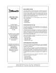
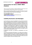
1. Remove Worktop: Using a Phillips Screwdriver, remove the
three screws located on the front underside edge of the
worktop and the three screws located at the rear (back)
side of the worktop.
See Fig's. 1 & 2
Remove the worktop from the cabinet and position the
worktop on top of the cabinet so that the front corners
are staggered across the front corners of the cabinet.
Fig. 1
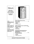
2. Installation of Top Rail: Attach the chrome rail to the work
top using four self-tapping screws from the underside of the
worktop through the pre-drilled holes. (attach the front ends
of the rail first)
3. Re-Install Worktop: Install the front of the worktop onto the
cabinet, then lower the rear side of the worktop over the
backside of the cabinet. Secure using the same screws
removed earlier. (the smaller screws at the front the larger
screws at the rear)
4. installation of CO2 Cylinder Support: Install the cylinder
support onto the four studs located on the exterior back
wall of the cabinet. (no tools required) Align the holes in
the cylinder support with the studs and push down firmly.
See Fig. 3
Fig. 2
Fig. 3
5. Installation of CO2 Cylinder: Install your "fully charged"
CO2 cylinder into the support stand. IMPORTANT NOTICE:
ALWAYS EXERCISE EXTREME CAUTION WHEN
HANDLING PRESSURIZED C02 CYLINDERS:
6. Installation of C02 Regulator: Attach the CO2 Regulator to
the C02 cylinder by screwing the regulator nut onto cylinder
valve and tighten (snug) using an adjustable wrench.
Fig. 4
7. installation of C02 Air Line Hose to Regulator: Attach one
end of the (red) air line hose to the hose barb connection
on the CO2 regulator. Secure hose by using one of the two
(self locking) black plastic snap on clamps provided.
(use pliers to snap the clamp tight to assure that there are
no leaks)
See Fig. 5
Fig. 5
e.]:II It Iki_mF_,I"./_,T_',_
_I;AI:] L'dl I_[_'._i
I :,laIN I [0] __I_o] _M
.
.
installation of CO2 Air Line inside Cabinet:
Remove rubber plug located at the exterior (top
right hand corner) of the cabinet. (store this
plug in a safe place, it will be required when
converting your unit back to a basic refrigerator)
Insert the open end of the air line into the
cabinet through the opening vacated by plug.
See Fig. 6
Remove the Chill 'n Tap Cabinet Plug (located
on top of worktop): Firmly grasp the cabinet
Chill 'n Tap plug, twist and pull upward. (store
this plug in a safe place, it will be required
when converting your unit back to a basic
refrigerator)
10. Installation of the Beer Tower (Quick Connect)
Locking Bayonet: Insert the locking bayonet
into the opening on the worktop. Align the "F"
indicated on top of the bayonet with the right
front corner of the worktop. (push and 1/4 turn
clockwise) The "F" represents the final
"FRONT" installation position of the beer tower.
(at the 6:00 o'clock position)
11. Installation of the Beer Tower Gasket: Position
the rubber (beer tower) gasket directly on top
of the bayonet aligning all four holes in the
gasket with the four holes on the bayonet.
12. Installation of the Beer Tower: Unravel the beer
line (hose) from the tower and insert the beer
line and "wing nut" through both the gasket and
bayonet. This will require a little maneuvering
by positioning (folding) the wing nut (together
with the beer line) in a "north/south" direction
and pushing it through the hole. Align the four
holes in the base of the beer tower, gasket and
bayonet. The beer faucet should be aligned
with the "F" on the bayonet and facing the front
Fig. 6
Fig. 7
of the cabinet. (6:00 o'clock position) Using a
Phillips Screwdriver, attach the beer tower to
the bayonet using four machine screws
provided and tighten firmly. To remove (unlock)
the beer tower assembly from the cabinet,
grasp the tower and 1/4 turn counter clock wise
(until it stops) and lift. This allows quick and
easy removal of the beer tower assembly when
converting the unit from the keg cooler
application to the "all refrigerator" application.
13. installation of the Beer Tower Faucet Handle:
Screw the black faucet handle (clockwise) onto
the beer tower faucet. (hand tighten only)
14. installation of the Protective Plate: To prevent
unnecessary damage (marring) to the floor of
the refrigerator cabinet, the protective plate
should always be installed when the keg stand
is being used. The protective plate also makes
installation and removal of the keg stand easier.
15, installation of the Beer Keg: Position the keg
stand directly in front of the open refrigerator
cabinet. Using proper lifting technique, (using
keg handles only) carefully lift the beer keg onto
the keg stand. See Fig. 7
NOTE: The keg stand is required when
using 30 Liter (1/4 barrel) kegs only. To install
the beer keg and stand inside the refrigerator
cabinet, brace your knees behind the keg stand
and grasp the keg stand handles. Lift the
front of the keg stand just enough so that the
front edge of the stand is resting on the front
edge of the refrigerator cabinet. See Fig. 8
Grasp the keg stand (front) handles and "care
fully" slide the keg stand all the way into the
refrigerator cabinet.
Fig. 8
d -"II I Ijl _Ii F;I".iV;_.!.I;l_VJl
:] li'| I__.']11
:_1[_1i [e] __.I[Ke] _i
16. Installation of the Keg Coupler: IMPORTANT
NOTICE; Make sure the black pull handle of the
keg coupler is in the "upward" (closed) position
before installing on the beer keg. See Fig. 9 Insert
the keg coupler into the locking neck of the beer
keg and apply a 1/4 turn clockwise to lock into
position.
17. Installation of the CO2 Air Line Hose to the Keg
Coupler: Attach the open end of the (red) air line
hose to the hose barb connection on the keg
coupler. Secure hose by using the remaining (self
locking) plastic snap on clamp provided. (use pliers
to tighten clamp and assure there are no leaks)
18. Installation of the Beer Line Hose to the Keg
Coupler: IMPORTANT NOTICE: The black rubber
washer (provided) must be installed inside the
wing nut before connecting the beer line to the keg
coupler. Remove the black rubber protective cap
located on top of the keg coupler and screw the
wing nut (with rubber washer) onto the keg
coupler. (hand tighten firmly)
19. Making the connection between the Keg
Coupler and Beer Keg: Before making (opening)
connection between the keg coupler and beer keg,
make sure the beer tower faucet is in the closed
position. (faucet handle straight back) To engage
the tank connection, pull the keg coupler handle
out and push down until it locks into position.
Listen for positive "click" of the pull handle in the
final downward position. See Fig. 10
When the secondary valve (handle) is positioned
"Vertical" (north/south) the valve is open.
To open the main C02 cylinder valve, (slowly) turn
the main valve counter clockwise until fully open.
You will notice the needles on both gauges start to
climb.
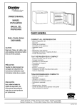
21. Adjusting the CO2 Regulator: There are two
pressure gauges on the CO2 regulator.
See Fig. 12 The upper gauge #1 monitors "LOW"
(internal keg) pressure and must be adjusted to
the correct operating pressure of 10~12psi/Ibs. The
lower gauge #2 monitors "HIGH" (CO2 cylinder)
pressure and is not adjustable. The high pressure
gauge also acts as a fuel gauge to let you know
when the C02 cylinder needs re-filling
IMPORTANT: The internal operating pressure of the
beer keg should be adjusted and maintained between
10 ~ 12psi/Ibs. To adjust the "low" pressure gauge;
• Using an adjustable wrench, release the adjustment
lock nut # 3. See Fig. 12
• Using a flat screwdriver, turn the regulator
adjustment screw # 4 See Fig. 12
Clockwise rotation of the adjustment screw will
increase low pressure.
Counter clockwise rotation of the adjustment screw
will decrease low pressure
• When the required operating pressure is attained
retighten the adjustment lock nut # 3.
• You are now ready to serve cold beer
20. Opening the C02 Cylinder Main Valve: Before
opening the main valve located on top of the C02
cylinder. Make sure the "secondary" shut-off valve
located on the lower stem pipe of the regulator is
in the "closed" position. See Fig. 11
NOTE: When the secondary valve (handle) is
positioned "Horizontal" (east/west) the valve is
closed.
I
Secondary
Valve
Fig. 9
Fig. 10
Fig.
11
Fig. 12
: [ol*AVil
lie] :,1:1".,I
I&To,]:IF;! _1:1;4 U Ik'io{o),_[o_'d! I_I ;] =:
1. Close the main cylinder valve (A) by turning in a
clockwise direction. See Fig.13
9. Readjust regulator pressure (D) (if necessary)
between 10 ~ 12 psi/Ibs.
2. Close the secondary shut-off valve (C) by
turning to "horizontal" (east/west) position on
lower stem pipe. See Fig.13
10. Open the secondary shut-off valve (C)by turning
to "vertical" (north/south) position on lower stem
pipe.
3. Remove the air line clamp and hose from the
regulator.
4. Remove the regulator assembly (E) from empty
cylinder. See Fig.13
5. Remove dust cap from new and/or replacement
CO2 cylinder
6. Re-attach regulator assembly (E) to
new/replacement cylinder. See Fig.13
7. Re-attach the air line hose to regulator (barb
connection) and secure with clamp.
Fig. 13
8. Slowly open main valve (A) all the way.
See Fig. 13
.la n I1_[dll-'ll
:_= i :_[_1= :f:| [o] :lii =;4-.i = :!:| ill :_q
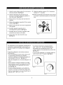
The temperature of the refrigerator compartment is
controlled by adjusting/setting the thermostat control knob, located on the ceiling of the refrigerator
cabinet.
To start the refrigerator, and achieve maximum
cooling quickly;
• Turn the temperature control knob (using a coin
or screwdriver) clockwise to the furthest
(maximum) setting on the darker blue section of
the graduated control dial. See Fig. 14
• To maintain temperatures ranging between
34°F ~ 38°F.(1°C ~ 3°C) We recommend the
thermostat knob be positioned at the "2:00
o'clock" setting on the graduated blue control dial.
See Fig. 15
• To turn off the refrigerator, (no cooling) rotate the
control knob to the "0" position. See Fig.14
• Allow the refrigerator to run at this setting for 3~4
hours.
• When maximum cooling is achieved, turn back
the temperature control knob setting to the 2:00
o'clock position on the graduated blue control
dial. See Fig. 15
o
Fig. 14
• Correct cooling temperature is a key factor to
consider in storing and dispensing draught beer.
• Optimum temperature for serving draught beer is
between 34°F ~ 38°F.(1°C ~ 3°C)
0
Fig. 15
Keep a thermometer handy. (adjust temperature control knob accordingly)
Periodically monitor temperatures inside your cooler. (adjust as necessary)
Keep the refrigerator door closed as much as possible to avoid temperature fluctuations
AUTOMATIC DEFROSTING:
There is no need to defrost the refrigerator, because ice depositing on
ically. Ice build-up on the evaporator during compressor operation; will
off) defrost automatically. Defrost water collects inside the drain trough
in the rear wall into a drain pan situated above the compressor, where
the evaporator is defrosted automat(when the compressor has cycled
and passes through the drain outlet
it evaporates.
CLEANING THE APPLIANCE:
Always disconnect the power cord before cleaning and/or servicing the appliance. Do not use coarse or
aggressive cleaning agents as they can damage painted surfaces. Clean the exterior cabinet with warm
water and a mild detergent. Clean the interior with warm water and a mild detergent, adding one or two
spoonfuls of vinegar. After cleaning, connect the appliance to power supply.
SWITCH OFF AND/OR DISCONNECT THE APPLIANCE WHEN NOT IN USE:
If you do not intend to use the appliance for long periods of time, (vacations) set the thermostat knob to the
"0" (off) position and disconnect the power cord. Take out all foods and clean the appliance. Leave the
door slightly open to reduce mold/mildew from accumulating inside the cabinet.
If you find the direction of the door swing on your appliance inconvenient, you can change it to the
opposite side. Simply follow the steps listed below.
.
2.
Lay the unit on it's back.
Remove the adjustable leveling leg from the lower right hinge.
3.
Remove two (2) screws from the lower door hinge.
4.
Open the main door and pull down, until the door releases from the upper door hinge pin.
5.
Remove the plastic door plug (cap) from the top left side of the main door.
6.
Re-install plastic door plug (cap) to the top right side of the main door
7.
Remove (unscrew) the upper door hinge pin. (right side cabinet)
8.
Re-install the upper door hinge pin. (left side cabinet)
9.
Position the main door back on the cabinet and push up until the top hinge pin is inserted
into the top of the door.
10.
Re-install the lower door hinge to the left side of the cabinet, using the same screws
removed earlier.
11.
Align the main door on the cabinet before tightening the lower hinge screws.
12.
Re-install the leveling leg back into the lower hinge.
13.
Return the unit back to the upright position.
14.
Allow the unit to stand 30 minutes before switching the unit on.
STORAGE
ANDHANDLING:
• Draught Beer should be treated as a food product. In most instances draught beer is not pasteurized.
It is very important that you store and handle it properly.
• Draught Beer should be immediately stored in a refrigerated cabinet.
• Draught Beer products have a shelf life, which on "average" is 30 days after the keg is tapped.
By keeping the beer keg pressurized, (with CO2) the shelf life can be extended (60 days)
• Beer Kegs should be stored (refrigerated) separately from other food products. It is very important that
food not be stored near or on the beer keg.
BEER TEMPERATURE:
• Correct temperature is a key factor to consider in storing and dispensing draught beer.
• Beer can freeze, so it is important to select and maintian proper operating temperatures inside the
refrigerator cabinet.
• Optimum temperatures for serving cold beer are 34° ~380 F (1 ° ~30 C)
• Temperatures too cool or too warm may cause flavour loss, off taste and dispensing problems.
CO2 PRESSURE:
• Periodically monitor the pressure regulators to ensure applied operating pressures remain constant.
(10 ~12psi/Ibs)
• Always keep equipment in good repair.
TAPPING KEG:
• Do not agitate kegs unnecessarily. If excessive agitation occurs (during transportation) allow keg to settle
for 1 ~2 hours before tapping.
• Prior to tapping the keg, ensure the beer faucet is in the off position.
• Completely remove the dust cover (identification cap) from the beer keg.
• Check that the keg coupler (handle) is in the up (off) position. See Fig. 9
• Insert the keg coupler into the locking neck of the beer keg and apply a turn clockwise to lock
into position.
• Pull keg coupler handle out and downward until it locks into position. See Fig. 10
This activates both the beer and (C02) pressure line.
The keg is now tapped and ready to draw beer,
CLEAN BEER GLASSES:
Keeping your glassware "beer clean" is the key to serving good draught beer. To achieve this:
• Maintain strict sanitary conditions in the glass washing area.
• Never wash glassware with utensils or dishes used to serve food, Food particles and/or residue can effect
the quality/taste of draught beer.
• Do not use regular liquid household dish washing detergents for glassware. They are fat-based and will
leave a slight oily film on the glass. This causes beer to go flat quickly. Use a detergent designed
specifically for beer glass cleaning. It must be low-suds, odor-free and non-fat.
• Avoid drying glassware with towels as they tend to leave traces of lint on the surface of the glass.
• We recommend that you use beer glassware only for beer. Dairy and other food products leave a residue
which can effect the quality/taste of the draught.
10
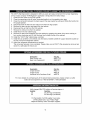
Therearetwo(2)standardsizebeerkegsthatcanbeusedinyourChill'NTapKegCooler.
30LiterKeg(1/4Barrel)yields3-1/2cases(1056ozs)
of beer.(KegWeight911bs
Full)
20LiterKeg( 1/6Barrel)yields2-1/2cases(704ozs)
of beer(KegWeight541bsFull)
Note:Thekegstandis requiredonlywhenusingthe30litersizebeerkeg.
IMPORTANT
NOTICE:
Beeris easilyavailable
withDanby'snewKegCoolerRefrigerator,
however,
it is notintended
to beavailabletopeopleunderthelegalagetoconsumebeer.OneoftheoptionsDanbyoffersisa locksothat
accesstotheicecoldbeercanbelimited.Danbydoesnotassumeliabilityfortheunlawfuluseorconsumptionofthebeer.PLEASE DON'T DRINK AND DRIVE!
•
•
•
•
•
Keep beer keg refrigerated at all times.
Never let beer lines empty or allow them to dry out.
Rinse the beer glass with fresh cold water before pouring.
Hold glass at a 450 angle, hold steady, when 2/3 full start to straighten glass and top it off.
When beer is dispensing through the faucet, condensation may form on the outer surface of the faucet.
This is a normal condition and cannot be avoided. This is caused by temperature differentials between
cold beer flowing across the warmer ambient surfaces of the inner faucet.
• Always make sure the faucet handle is pushed fully back (closed) to prevent excess dripping.
• A beer faucet lock kit for the purpose of limiting access, is readily available and can be purchased
through our after sales service department at 1-800 26-DANBY (1-800-263-2629)
_ II :lr±1#II #[€]1:1:1:1t,i III# I#_.
Why do dispensing lines have to be cleaned?
Beer lines have to be cleaned because a scale called calcium oxalate, commonly referred to as "beerstore" forms on the fittings, lines and taps.
"Beerstore", if not completely removed in a cleaning process will leave an unsanitary surface that can harbour microorganisms.
Line cleaning, with the proper equipment and chemical, eliminates the build-up of 'beerstore" protecting
the integrity of the product.
Microorganisms or bacteria will grow very quickly if a sanitary environment is not maintained, causing "offflavours" or shorten the shelf life of beer.
Regular cleaning assures that bacteria does not have the opportunity to reach levels which affect the
quality/taste of the beer.
Line cleaning should be done on a regularly scheduled basis.(approximately every 6 weeks)
A standard cleaning kit will perform approximately eight (8) scheduled line cleanings.
Line cleaning kits are readily available and can be purchased through our after sales service department.
For more information please call 1-800 26-DANBY (t-800-263-2629)
11
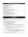
_o] _LvJ:lr,t i I_[€']i I" I:[_]" Il! lid _II It:1"J[4 :[€'[e[oIo] I! :1:| _o1:1 :Y:_ [_:I
! q :__ _ :_[_ _ :;:_ |o] _
The Chill 'N Tap Keg Cooler is designed to offer you quick and easy conversion from a beer dispensing
unit to a basic compact "All Refrigerator" application, Simply follow the below steps;
1. Close the main valve on the CO2 cylinder.
2. Close the secondary shut-off valve (horizontal position) on the regulator stem pipe.
3. Close the connection between the beer keg and the keg coupler by pulling and lifting the handle into
the upright position.
4. Disconnect both the beer line and CO2 air line from the keg coupler,
5. Remove the beer keg and keg stand from the cabinet,
6. Disconnect the air line from the CO2 cylinder,
7. Remove the CO2 air line from the cabinet.
8. Install the air line rear cabinet plug.
9. Remove the beer tower assembly from the cabinet by grasping the center of the tower making a i
turn counter clockwise and lift. (pull the beer line through the top of the cabinet)
10. Install the "Chill 'N Tap" cabinet plug. (worktop)
11. Install the (2) cantilever wire shelves onto the factory installed cantilever support brackets located on
the rear wall of the refrigerator cabinet.
12. Adjust the refrigerator temperature as required.
The conversion process is now complete, Please make sure all Chill 'N Tap accessories removed are
stored in a safe place for future use.
o] "Ji [e]_r:1IF:T@][@]
:(_1.'[e]rJI:_11_[e]r,t[e]" IIII_ _l _:I d :4_eIe]
Description
Beer Faucet Lock.
Beer Line Cleaning Kit.
| _ _i
Part No.
#445-7703
#445-5571
;]"Ji [e]_r:! IF:T_@]:(_'T:[o]rJI:(_1_[o]r,tV:! II II r,_:1_1r,_[_ _ :!:_ (el _i
Description
Crisper Drawer
Crisper Cover
Additional Wire Cantilever Shelf
Part No.
#452. tC
#452.28
#452.33
For more details on purchasing any of the above listed accessories, please contact our after
sales service department at 1-800-26-DANBY (1-800-263-2629).
:I ;] ;] i i [o]#r:1II I#I_[o]r,lLv_
r:l i [o]#[el #[e[o]_
Afully charged (51b).CO2cylinder will service (approx.):
Quantit,z
Kea Size.
20
30 Liter Kegs (t/4 Barrels)
25
20 Liter Kegs (1/6 Barrels)
For the location of a CO2 supplier in your area,
(re-fills) please look in your "Yellow Page"
telephone directory under "OXYGEN" suppliers.
12
nby
° LIMITED
PRODUCT
WARRANTY
This qualityproductis warrantedto befree frommanufacturer'sdefectsin materialandworkmanship,providedthat theunit is usedunderthe normaloperating
conditionsintendedbythemanufacturer.
This warrantyis availableonly to thepersonto whomtheunit wasoriginallysoldby Danbyor byan authorizeddistributorof Danby,andis non-transferable.
TERMSOFWARRANTY
Plasticparts(ie. evaporatordoor,door rails,coversandtrays arewarrantedfor thirty (30)days onlyfrompurchasedate,withno extensionsprovided.
First Year
Duringthefirst year (1),any electricalpartsof this productfoundto be defective,includinganysealedsystemunits,wilI berepairedor
replaced,at warrantor'soption,at no chargeto the ORIGINALpurchaser.
Consumableparts(ie. lightbulbs)are notwarrantedor guaranteedfor any lengthof time.
SecondThrough
Duringthe nextfour years(4)any part of thesealedsystemfoundto be defective(consistingof compressor,condenser,evaporator,
Fifth Year
dryerandalIrelatedtubing)will bereplacedwithoutcharge.The purchasershallpay for all labourandreturnfreightduringthis four
year(4)periodfor repairor replacementof any sealedsystemcomponents.Any unit beingdiagnosedas non-functionaldueto sealed
systemfailureandwarrantingan exchangeduringthe existingfour (4)yearswill be subjectto an appropriatedepreciationor userfee,
includingany and allfreightchargesbeingleviedagainsttheconsumer.
Toobtain
Service
Contactyourdealerfromwhomyourunit waspurchased,or contactyournearestauthorizedDanbyservicedepot,whereservice
mustbe performedby a qualifiedservicetechnician,tf serviceis performedonthe unitsby anyoneotherthanan authorizedservice
depot,or the unit is usedfor commercialapplication,all obligationsof Danbyunderthis warrantyshallbeat an end.
The followingclauserefersto singleanddoubledoorrefrigerators,suppliedwithor withouta separatefreezersection. Nothingwithinthis warrantyshallimply
that Danbywill be responsibleor liablefor anyspoilageor damageto food or othercontentsof this appliance,whetherdueto any defectof the appliance,or its
use, whetherproperor improper.
EXCLUSIONS
Saveas hereinprovided,DanbyProductsLimited(Canada)or DanbyProductsInc.(U.S.A.),thereare no otherwarranties,conditions,representationsor guarantees,expressor implied,madeor intendedbyDanbyProductsLimitedor its authorizeddistributorsandall otherwarranties,conditions,representationsor
guarantees,including
any warranties,conditions,representationsor guaranteesunderany Saleof GoodsAct or Iike legislationor statuteis herebyexpressly
excluded.Saveas hereinprovided,DanbyProductsLimited(Canada)or DanbyProductsInc. (U.&A), shallnotbe responsiblefor any damagesto personsor
property,including
the unit itself,howsoevercausedor anyconsequentialdamagesarisingfrom themalfunctionof theunit and bythe purchaseof the unit,the
purchaserdoes herebyagreeto indemnifyandsaveharmlessDanbyProductsLimitedfrom any claimfor damagesto personsor propertycausedbythe unit.
GENERALPROVlSIONS
Nowarrantyor insurancehereincontainedor setoutshalIapplywhendamageor repairis causedbyany of thefollowing:
1) PowerFailure.
2) Damageintransitor when movingthe appliance.
3) improperpowersupplysuchas lowvoltage,defectivehousewiringor inadequatefuses.
4) Accident,alteration,abuseor misuseof the appliancesuchas inadequateair circulationin theroomor abnomlaloperatingconditions,
(extremelyhigh or low roomtemperature).
5) Usefor commercialor industrialpurposes.
6) Fire,water damage,theft,war, riot,hostility,acts of Godsuchas hurricanes,floodsetc.
7) Servicecallsresultingincustomereducation.
Proofof purchasedatewill be requiredfor warrantyclaims;so,pleaseretainbillsof sale. Inthe eventwarrantyserviceis required,presentthisdocumentto our
AUTHORIZEDSERVICEDEPOT.
Warrantv
Compacts
DanbyProductsLimited
EO. Box1778,Guelph,Ontario,Canada N1H6Z9
Telephone:(519)837-0926FAX: (519)837-0449
Canada
In Home
Service
United States
In Home
11/OO
DanbyProductsInc.
EO. Box 669,Findlay,Ohio,U.S.A. 45839-0669
Telephone:(419)425-8627FAX: (419)425-8629