1
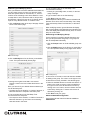
Installation Instructions
Please Read Before Installing
HomeWorks®/AMX inconcert Processor
HP5-H48-AMX-120 (AMX Model: ALD-H48-AMX-INT)
12 V
60 Hz 30 VA
Overview
The HP5-H48-AMX-120 Processor allows connection of
HomeWorks Wired Keypads and HomeWorks Wired
Maestro® Local Lighting Controls. The central processor
provides lighting presets and easy integration into an
AMX system.
A maximum of 24 Designer-Style keypads may be
connected to and powered by the Keypad Link on the
HP5-H48-AMX-120 Processor.
Important Notes
Figure 1 - HP5-H48-AMX-120 Processor
Codes: Install in accordance with all local and
national electrical codes.
Installation
Power: Two separate power inputs exist on this
processor:
1. Processor power is provided by the 2 conductor
harness that is integral to the HWI-LV24 enclosure. The processor is powered when the green
LED labeled “PWR” is on.
2. Connected keypads are powered by the supplied
plug-in adapter connected to the power jack
labeled “Keypad Link 15 V ”. The Keypad Link
is powered properly when the green “Keypad
LINK PWR” LED is on. If the red “LINK SHORT”
LED is on, the Keypad Link is shorted (between
terminal 1 and 2) or overloaded (exceeding 150
LEDs).
1. Ensure High-voltage cover in HWI-LV24 enclosure is
securely installed. Locate and lock supply breaker in
the OFF position before installing processor assembly.
Danger - Wiring with power on may result in
personal injury.
2. Install processor assembly in the enclosure: The
HP5-H48-AMX-120 Processor is attached to the HWILV24 enclosure using four mounting keyholes and the
mounting screws provided.
The HP5-H48-AMX-120
Processor mounts in the upper
left corner of an HWI-LV24
enclosure.
Both Processor power and Keypad Link power must
be present for the processor and keypads to function
properly.
Processor Power: 12 V
Keypad Link Power: 15 V
30 VA
900 mA NEC Class 2;
IEC PELV
Use only the adapter provided by Lutron with
the HP5-H48-AMX-120 Processor.
Environment: Ambient operating temperature:
0-40 °C, 32-104 °F, 0-90% humidity, non-condensing.
Indoor use only.
Cleaning: To clean, wipe with a clean damp cloth. DO
NOT use any chemical cleaning solutions.
High-voltage enclosure
(shown with cover installed).
Figure 2 - Mounting
Diagram
3. Ensure all DIP
switches are in the down position.
Example: Setting Switch #6 ON.
Down (OFF)
Up (ON)
4. Connect to HomeWorks lighting controls. Connect
the communication wiring from the HomeWorks
Maestro Dimmers to the factory installed Dimmer Hub.
See Figure 3, page 2. Gray and violet connections are
marked on the printed circuit board.
1
5. Connect Keypad link: For keypads that are to be
controlled by this Processor, connect the communication wires to the Keypad Link.
6. Connect power. Plug the power input harness terminals (blue wires) from the HWI-LV24 enclosure onto
the power feed lugs on the HP5-H48-AMX-120
Processor. Connect plug from adapter to Keypad Link
Power connector. Plug adapter into receptacle in
bottom of HWI-LV24 enclosure. The HP5-H48-AMX120 Processor has battery-backed memory. The
battery provides power during power outages and
other temporary power interruptions. In vacation
homes and other residences which are not
continuously occupied, the Processor MUST be
powered by a circuit that is never turned off even
when the residence is unoccupied.
7. Turn power ON. Restore the supply breaker to the
ON position.
8. Connect Ethernet Link. Connect a standard RJ45
connector to the Ethernet jack on the Processor. If
plugging into a network, a standard cable is used (see
Figure 4). The orange LED (ACT) will illuminate when
there are any Ethernet signals being transmitted or
received. The green LED (CON) will illuminate when
the Processor is connected to a hub/switch/router or a
computer.
Mounting
Keyhole (4
places)
To HomeWorks® Wired Maestro®
controls
Dimmer
Hub
Processor
Label
Ethernet Port
Processor
Board
To HomeWorks
Keypads
Figure 3 - HomeWorks/AMX inconcert Processor
Quick Start Guide
For more detailed programming instructions, refer to the
ALD-H48 Instruction Manual available on-line at
www.amx.com.
Overview
The ALD-H48 from AMX is a Lutron lighting solution with
a complementary Duet module. The result is a Lutron
device that functions within a NetLinx project.
After you have installed the ALD-H48, using the installation documentation included with the unit, you can create
a NetLinx project and configure the dimmers. You need
NetLinx Studio v2.3 or higher and a NetLinx Master capable of running Duet modules (firmware version 3.0.XXX
or higher).
Using the web interface capabilities of your NetLinx master you can configure dimmers connected to your ALDH48.
The web interface supports:
• Internet Explorer v 6.0 (and higher)
• Mozilla Firefox v 1.0 (and higher)
Step-By-Step Instructions
Step 1: Downloading The ALD-H48 Workspace
First you must attain the ALD-H48 Workspace file
(.AXW). To download the Duet module go to either
amx.com > Dealers > InConcert or the Product Catalog
page for the ALD-H48. From the InConcert page you can
search for and download the ALDH48 Duet module, they
are indicated by the D within the legend displayed below.
L232>. At the prompt type SETIP,1, xxx.xxx.xxx.xxx .
Follow the onscreen instructions from this point.
(Where 1 is the number of processors present on the
H48 and xxx.xxx.xxx.xxx is the IP address to be
decided by you.)
Further, at the prompt type HELP and a list of all supported command is displayed. In order to get the correct syntax to set the IP address type at the prompt HELP,
SETIP.
Step 3: Opening The ALD-H48 Workspace
After you have downloaded the ALD-H48 Workspace file
you need to open your NetLinx project. The .AXW file
provided by AMX is intended to be a starting point for
your ALD-H48 project.
5. Launch NetLinx Studio v2.3 or higher.
6. Select File > Open Workspace to launch the Open
Workspace dialog.
7. Browse to the location where you saved the ALD-H48
Workspace file (.AXW) and click Open.
8. Manually enter the IP address assigned to the ALD-48
within Lutron_H48_UI.axs and then recompile the project before transferring it to the NetLinx Master.
You can also make any additional edits to the ALD-H48
project or elect to send the file to the NetLinx Master as
is.
Step 4: Transferring The ALD-H48 Project to A
NetLinx Master
NetLinx Studio can transfer the ALD-H48 project file to
any connected NetLinx Master with firmware version
3.XX or higher.
1. Select Tools > File Transfer to open the File Transfer
dialog.
FIG. 1 Module Legend
2. If the Workspace file is not already listed in the window
click Quick Load to open the corresponding dialog.
Included in the .AXW file:
3. In the drop down list select the ALD-H48 Workspace.
• The NetLinx Main Code (.AXS)
4. Click Select All.
• The Duet module (.JAR)
5. Click OK.
• Associated TPD4 files
6. Make sure there is a check in the box next to the ALDH48 workspace within the File Transfer dialog and
click Send.
Step 2: Setting The ALD-H48 IP Address
In order for the NetLinx Master to locate the ALD-H48,
you must set the IP address for the device.
1. Connect your PC to the H48 serial port using a standard DB-9 serial cable.
2. Open your preferred serial client (HyperTerm, TELNET,
etc...)
3. Make sure your serial connection baud rate and handshaking settings match the H48 serial settings.
(Default Baud Rate 9600, Data Bits: 8, Parity: None,
Stop Bits: 1, Flow Control: None)
4. Upon a successful connection, you are prompted with
3
Step 5: Addressing The Dimmers via The Web
Interface
Once you have installed the ALD-H48 and dimmers using
the hardware installation literature included with the unit,
you must now address the dimmers.
Controlling Dimmers via the Web Page
Once a dimmer has been addressed, you have access to
a few basic level controls from the master’s web page.
1. Click the button Dimmer Control to open the Dimmer
Control page.(FIG. 4)
You can only select addresses available on the bus to
which the dimmer is physically connected. For example,
if you want to assign address 17 to a particular dimmer, it
must be connected to bus 3 of the ALD-H48 as indicated
below.
Bus Address Location
Bus
1
2
3
4
5
6
Address
1-8
9-16
17-24
25-32
33-40
41-48
To address the dimmers:
1. Using your web browser, go to the target NetLinx
Master’s web page. Note: Refer to the NetLinx Master
documentation for more detailed information concerning the NetLinx Master Web Interface.
2. Click on Lights and all connected modules are displayed below Lights. There is only one module per
device.
Upon your first visit to Lights, the page will have the following message, FIG. 2.
FIG. 2 Initial Lights Configuration Page
3. Click Address Mode to set the master to look for
available dimmers.
4. Tap the dimmer you wish to address three times to
make it available to the master.
5. The displayed addresses are only those that are available on that physical bus that have not been used.
Bold text indicates the address has already been
assigned. Pick an available number and click Select to
address the dimmer.
FIG. 3 Dimmer Address
4
FIG. 4 Dimmer Control
Listed in the column on the left are all dimmer addresses
available for control. On the right is a percentage bargraph representation of the current state of the selected
dimmer.
2. To change the state of a dimmer, select a dimmer
address in the column on the left.
• Click on 100% to ramp the dimmer completely on and
0% to ramp the dimmer off.
• Click within the bargraph area on the right to shift the
dimmer state up and down to a desired percentage.
Establishing And Modifying Scenes
Once your dimmers have been addressed and states set,
you can create a scene. A scene is a collection of dimmers with specific states for each dimmer, i.e., Scene 1
could be set as a meeting scene where Dimmers 1 and
12 ramp down to 45%, Dimmers 6 and 14 ramp to 80%
and Dimmers 2 through 5 ramp to 0%. A dimmer can be
a part of many different scenes. To create a scene:
1. Click the Scenes button at the top of the page. Shown
below is the Scenes page.
5. Type a number value in the field Ramp Time.
The next field is intensity.
• Intensity is a percentage value, 0-100%, for the luminosity of the light.
6. Type a number value in the field Intensity.
7. Click Save to set your scene.
Global Adjustment allows you to select and deselect all
dimmers at one time, and to set the Delay Time, Ramp
Time and Intensity values for all dimmers, to the same
value.
When modifying scenes, ignored dimmers will display
their current intensity level while dimmers included in the
scene will display their defined intensity level, not necessarily the current state.
Establishing And Modifying Groups
For the purpose of controlling several dimmers at one
time you can place them into groups. The groups can
then be manipulated collectively.
1. Click the Groups button to list all available group numbers.
2. Click the Modify button for the Group you would like to
set. This opens the Modify Group page, shown below.
FIG. 5 Scenes Page
2. Click the Modify button for the Scene you would like
to set. This opens the Modify Scene page.
FIG. 7 Modify Group
FIG. 6 Modify Scene
3. Moving left to right the first field is a check box.
Placing a check in the box includes the dimmer in the
scene.
Once you have all of your desired dimmers selected you
can set the Delay time.
• The delay time is the duration, in 1/10ths of seconds, it
takes the dimmers to respond to the button push.
4. Type a number value in the field Delay Time.
The next field is the ramp time.
• The ramp time is the duration, in 1/10ths of seconds, it
takes the dimmers to go from their current intensity
state to that set in the scene.
In the column on the left is a list of all dimmers available
for adding to the group. The column on the right is a list
of all dimmers currently included in the selected group.
3. Select an available dimmer on the left and click the “>”
button in the center to move it to the included list on
the right. You can move all dimmers at one time by
clicking on the “>>” button, remove a dimmer from the
scene list by clicking the “<” button and remove all
dimmers by clicking “<<”.
4. Click Save to set your group.
Advanced ALD-H48 Configuration
Consult the ALD-H48 Instruction Manual available at
www.amx.com.
5
Notes:
6
Notes:
7
Technical and Sales Assistance
AMX
If you need assistance, call the toll-free AMX
Technical Support Center. Please provide exact
model number when calling.
1.800.222.0193
Tel: 469.624.8000
www.amx.com
Lutron
If you need assistance, call the toll-free Lutron
Technical Support Center. Please provide exact
model number when calling.
1.800.523.9466 (U.S.A., Canada and the Caribbean)
Other countries call:
Tel: 610.282.3800
Fax: 610.282.3090
Visit our Web site at www.lutron.com
Lutron Electronics Co., Inc.
7200 Suter Road
Coopersburg, PA 18036-1299
Made and printed in the U.S.A. 7/05 P/N 043-222 Rev. A
LIMITED WARRANTY
Lutron will, at its option, repair or replace any unit that is defective in materials or manufacture within two years after purchase. For warranty service, return unit to place of purchase or
mail to Lutron at 7200 Suter Rd., Coopersburg, PA 18036-1299, postage pre-paid. Telephone
the Lutron Technical Support Center toll free at 800-523-9466. After the two year period, a
pro-rated warranty applies to this product until eight years after the purchase. For more information regarding this warranty contact your Lutron representative.
THIS WARRANTY IS IN LIEU OF ALL OTHER EXPRESS WARRANTIES, AND THE
IMPLIED WARRANTY OF MERCHANTABILITY IS LIMITED TO TWO YEARS FROM PURCHASE. THIS WARRANTY DOES NOT COVER THE COST OF INSTALLATION,
REMOVAL OR REINSTALLATION, OR DAMAGE RESULTING FROM MISUSE, ABUSE,
OR IMPROPER OR INCORRECT REPAIR, OR DAMAGE FROM IMPROPER WIRING OR
INSTALLATION. THIS WARRANTY DOES NOT COVER INCIDENTAL OR CONSEQUENTIAL DAMAGES. LUTRON’S LIABILITY ON ANY CLAIM FOR DAMAGES ARISING OUT
OF OR IN CONNECTION WITH THE MANUFACTURE, SALE, INSTALLATION, DELIVERY,
OR USE OF THE UNIT SHALL NEVER EXCEED THE PURCHASE PRICE OF THE UNIT.
This warranty gives you specific legal rights, and you may also have other rights which vary
from state to state. Some states do not allow limitations on how long an implied warranty lasts,
so the above limitation may not apply to you. Some states do not allow the exclusion or limitation of incidental or consequential damages, so the above limitation or exclusion may not
apply to you.
AMX and the AMX logo are registered trademarks and in concert and the inconcert logo are
trademarks of AMX, Inc., Richardson, TX. Lutron, HomeWorks, Maestro, GRAFIK Eye, the
sunburst logo, and the HomeWorks logo are registered trademarks of Lutron Electronics Co.,
Inc.
© 2005 Lutron Electronics Co., Inc.