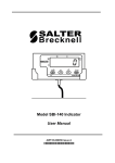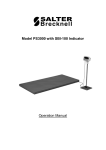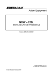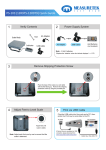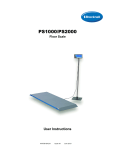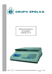
1
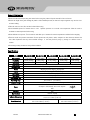
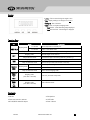
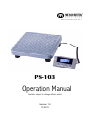
W W W. M E A S U R E T E K . N E T PS-103 Operation Manual Contents subject to change without notice Version 1.0 11/2011 General Information Read and understand all operating instructions before using this product. Keep this manual for future reference. Record the weight shortly after loading the platform. After extended periods, the load cell’s output signature may result in a less accurate reading. Place the scale on a hard, flat, and level surface before using. Avoid extended exposure to extreme heat or cold. Optimum operation is at normal room temperature. Allow the scale to acclimate to room temperature before using. Allow sufficient warm up time. Turn the scale on and allow up to 2 minutes for internal components to stabilize before weighing. Electronic scales are precision instruments. Do not operate near cell phones, radios, computers or other electronic devices that emit radio frequencies that may cause unstable readings. If the scale performs poorly, try moving to a different room or location. Avoid using in heavy vibration or heavy airflow conditions. Specifications Model PS-103-35 Max Capacity Readability Resolution Construction Weighing Units Modes Display Zero Range Tare Range Stabilization Time Operating Temp. Humidity Range 77lb (35kg) 0.05lb (0.02kg) 1:1750 Power Interface Max Overload Indicator Dimensions Base Dimensions PS‐103 PS-103-68 PS-103-75 PS-103-180 PS-103-200 150lb (68kg) 165lb (75kg) 397lb (180kg) 440lb (200kg) 0.5lb (0.2kg) 0.1lb (0.05kg) 0.5lb (0.2kg) 0.2lb (0.1kg) 1:300 1:1500 1:900 1:2000 Epoxy painted carbon steel, treaded surface kg / lb / lb:oz Weighing, Dynamic weighing, Display hold 0.58” (15mm) 7-segment LCD, 51/2 digits +20% of full capacity Full capacity <3 seconds 40° to 105°F (5° to 40°C) <90% relative humidity, non-condensing Alkaline Batteries: 4 x “AAA” size cells AC Adapter: 6Vdc/500mA, with central negative: USB USB 120% of capacity 5.73 x 2.08 x 0.71” (L x W x H) 145.5 x 53 x 18mm (L x W x H) 12” x 12” x 2.28” (L x W x H) 12” x 12” x 2.52” (L x W x H) 305 x 305 x 58mm (L x W x H) 305 x 305 x 64mm (L x W x H) www.measuretek.net . 1 . Display >0< - Scale is zeroed and gross weight is zero. Net - Display reading is net weight; tare is not 0. lb, kg, oz - Unit of measure. Hold - Scale is in dynamic weighing mode. - Hold flashes - actual fluctuating weight displayed. - Hold does not flash - locked weight is displayed. Function Keys KEY PRINT/ HOLD MODE Weighing mode <3 seconds Sends output data via the USB port >3 seconds Enters or exits HOLD mode Setup or Calibration mode UNIT TARE ON/OFF/ ZERO Weighing mode Setup/Calibration mode Weighing mode Setup or Calibration mode Weighing mode Shifts the flashing data entry position from right to left Chooses weight unit of measure Increases the digit in the flashing data entry position by 1 Tares the weight Confirms the input data and forwards to next step <3 seconds Zeros the platform weight >3 seconds Powers off the scale Setup or Calibration mode ON/OFF/ ZERO + UNIT ON/OFF/ ZERO + TARE DEFINITION Exits to normal weighing mode Weighing mode (more than 3 seconds) Enter user parameter setup mode. Weighing mode (more than 3 seconds) Enter calibration mode Contents Indicator Scale platform Cable from load cell to indicator 6’ USB cable AC120V/DC6V 500mA UL adaptor Owner’s Manual PS‐103 www.measuretek.net . 2 . Calibration Mode Note: A standard calibration weight of at least 10% of the scale’s rated capacity is required. The calibration operation must be in pounds. Press ZERO/ON/OFF at any time to exit calibration mode. Using 80% to 100% of the scale’s rated capacity is recommended for optimum results. 1. From normal weighing mode, press TARE and ZERO/ON/OFF until “CAL-?” is displayed. 2. Within calibration mode: Press PRINT/HOLD to shift the flashing data entry position from right to left Press UNIT to increase the digit in the flashing data entry position by 1 Press TARE to confirm and save the set data and enter next setting Press ZERO/ON/OFF key to exit this mode 3. Press TARE to confirm and enter calibration mode. 4. “CAL.P0“will be displayed to calibrate scale’s zero-point. Remove all weight from the scale platform and press TARE to confirm and move to the next step, or press ON/OFF to exit. 5. “CAL.P1“ will be displayed and the scale will be ready to accept the next calibration point. The default calibration input weight will be 50% of the scale’s rated capacity. Use the PRINT/HOLD and UNIT keys adjust to the standard calibration weight you will use. Note: do not use less than 10% of the scale’s rated capacity. and press TARE to confirm your input and move to the next step. Place the standard calibration weight on the platform If “CAL.Er” is displayed, press ZERO/ON/OFF key to exit this mode and begin again. 6. “CAL.P2“ will be displayed and the scale will be ready to accept the next calibration point. This step is optional, but better linearity will be achieved by calibrating to a second point. To skip this step, press the TARE key. Otherwise, the default calibration input weight will be 100% of the scale’s rated capacity. Use the PRINT/HOLD and UNIT keys adjust to the standard calibration weight you will use. Note: do not use less than 20% of the scale’s rated capacity. calibration weight on the platform and press TARE Place the standard to confirm your input and move to the next step. If “CAL.Er” is displayed, press ZERO/ON/OFF key to exit this mode and begin again. 7. “CAL.P0“will be displayed again. Remove all weight from the platform and press TARE to confirm and enter normal weighing mode. PS‐103 www.measuretek.net . 3 . User Parameter Setup Mode 1. From normal weighing mode, press UNIT and ZERO/ON/OFF until “USer” is displayed. 2. Within user parameter setup mode: Press PRINT/HOLD to shift the flashing data entry position from right to left Press UNIT to increase the digit in the flashing data entry position by 1 Press TARE to confirm and save the set data and enter next setting Press ZERO/ON/OFF key to exit this mode Parameter Default U1 05 U2 2 U3 2 U4 0 U5 1 U6 3 U7 0 PS‐103 Setting Auto-off time: 0 = No auto-off function 01-15 = Scale will auto power off after 1-15 minutes with no activity Backlight on-off mode option: 0 = Backlight is always off 1 = Backlight is always on 2 = Backlight is auto-off after 10 seconds with no activity PRINT/HOLD key function set: 0 = Hold only 1 = Print only 2 = Hold and Print Hold function mode: 0 = No hold function 1 = Holds the largest weight reading 2-50 = Displays the stable weight within 3 seconds. Note: When weight exceeds 10d and the variation is within ±2d~±50d, the stable weight is displayed until less than 10d is detected on the platform. 1d = 1 division = 1 unit of readability as noted in Specifications Serial communication output format: 0= Communication is disabled 1 = Outputs stable weight, unit, and status when PRINT/HOLD is pressed, but does not receive data 2 = Output gross, tare, net weight, unit, and status when PRINT/HOLD is pressed, but does not receive data 3 = Continuously outputs displayed weight, unit, and status, but does not receive data 4 = Continuously outputs gross, tare, net weight, unit, and status, but does not receive data 5 = Outputs weight, unit, and status one time after scale is becomes stable 6 = Outputs gross, tare, net weight, unit, and status one time after scale becomes stable 7 = Two way communication mode Baud rate for Serial communication: 0 = 1200 3 = 9600 1 = 2400 4 = 19200 2 = 4800 Serial communication byte format: 0 = 8N1 – 8 data bits, no parity, 1 stop bit 1 = 7O1 – 7 data bits, 1 bit odd parity, 1 stop bit 2 = 7E1 – 7 data bits, 1 bit even parity, 1 stop bit www.measuretek.net . 4 . Serial Communication Loadcell Power USB Before using the USB communication port, download the USB driver from http://www.measuretek.net/Download.html Detailed Serial (USB) Output Information: U5=0: No serial communication. No data transmitted or received even if the scale is installed with serial communication hardware. U5=1: Pressing PRINT/HOLD will output the current stable weight, weight unit, and current status data in the following format, but will not receive data: <LF>< weight, minus, decimal point, weight unit><CR><LF> H1H2H3 <CR><ETX> U5=2: Pressing PRINT/HOLD will output the current stable gross weight, tare, net weight, weight unit and current status data in the following format, but will not receive data: <LF><Gross: reading, minus, decimal point, unit><CR> <LF> <Tare: reading, decimal point, unit><CR> <LF> <Net: reading, minus, decimal point, unit><CR> <LF> H1H2H3<CR><ETX> Bytes used: 8 - Weight reading 1 - Minus 1 - Decimal point 2 or 5 3 - Weight unit Current status (H1.H2.H3) U5=3: Continuously outputs the current displayed reading, weight unit, and current status data, but will not receive data. The output format is the same as U5=1. U5=4: Continuously outputs the current gross weight, tare weight, net weight data, weight unit, and current status data, but will not receive data. The output format is the same as U5=2. U5=5: When the scale is stable, it will output the current displayed reading ,weight unit, and current status data automatically one time, but will not receive data. The output format is same as U5=1. U5=6: When the scale is stable, it will output the current gross weight, tare weight, net weight unit, and current status data automatically one time, but will not receive data. The output format is same as U5=2. U5=7: Two way communication. PS‐103 Responses to serial commands will be immediate, or within one www.measuretek.net . 5 . Serial Communication (continued) weight measure cycle of the scale. One second is adequate for use as a time-out value by remote (controlling) device. After receiving an available command, the indicator will send out the corresponding messages: For normal operation, weight data will be 8 digits long; minus sign will be 1 digit; decimal point will be 1 digit; and unit of measure will be 2 digits if “lb” or “kg”, and 5 digits if “lb:oz”. Unit of measure abbreviations are always lower case. If the weight is over capacity, the scale will return ten ‘^’ characters (the minus sign, decimal point, and weight data fields are filled by ‘^’). If the weight is under capacity or if there is a zero point error, the scale will return ten ‘_’ characters. The minus ‘-’ character indicates negative weight, and a space ‘ ’ character indicates positive weight. The minus sign follows after the first digit. Leading zero digits are suppressed. Serial Communication Symbols <LF> <CR> <ETX> <SP> H1H2H3 <p> W1-W8 <dp> U1U2 Line Feed character (hex 0AH) Carriage Return character (hex 0DH) End of Text character (hex 03) Space (hex 20H) Three status bytes (see below for byte definitions) Polarity (minus sign for negative weight and space for positive weight) Weight data Decimal point Measure units, “kg”, “lb”, or “lb oz” Status Byte Definitions Bit 0 1 2 3 4 5 6 7 PS‐103 Byte 1 (H1) 0=stable 1= not stable 0= not at zero point 1= at zero point 0=not AD over 1=AD over 0= eeprom OK 1= eeprom error always 1 always 1 always 0 parity Byte 2 (H2) 0= not under capacity 1= under capacity 0= not over capacity 1= over capacity 0=not zero over 1=zero over 0=not zero down 1= zero down always 1 always 1 always 1 parity www.measuretek.net Byte 3 (H3) 01=normal work mode 10= hold work mode 00=not defined 11= not defined 0= gross weight 1= net weight 0=not AD down 1=AD down always 1 always 1 always 0 parity . 6 . Serial Communication (continued) Serial Commands and Responses Command: S<CR> (53h 0dh) Response: <LF> H1H2H3<CR><ETX> Command: W<CR> (57h 0dh) Responses: over capacity: <LF>^^^^^^^^^^u1u2<CR><LF>H1H2H3<CR><ETX> under capacity: <LF>_________u1u2<CR><LF> H1H2H3<CR><ETX> zero-point error: <LF>----------u1u2<CR><LF> H1H2H3<CR><ETX> Note: If the weight unit is lb:oz, U1U2 = “lb oz” in above item ①②③. Normal weight is displayed, current weight unit is kg or lb: <LF><p>w1w2w3w4w5w6<dp>w7w8u1u2<CR><LF>H1H2H3<CR><ETX> Normal weight is displayed, current weight unit is lb:oz, <LF><p>w1w2w3w4w5w6lb<sp>w7w8<o><z><CR>H1H2H3<CR><ETX> <LF><p>w1w2w3w4w5lb<sp> w6w7<dp>w8oz<CR>H1H2H3<CR><ETX> or Command: Z<CR> (5ah 0dh) Response: <LF> H1H2H3<CR><ETX> Zero function is activated and returns to current scale status, like pressing ZERO/ON/OFF. If zero function cannot be activated, it will return to current scale status. Command: T<CR> (54h 0dh) Response: <LF> H1H2H3<CR><ETX> Tare function is activated and returns to current scale status, like pressing function cannot be activated, it will return to current scale status. TARE . If tare Command: U<CR> (55h 0dh) Response: <LF>u1u2<CR><LF> H1H2H3<CR><ETX> Changes unit of measure and returns to current scale status with new units, like pressing UNIT button. Command: L<CR> (4ch 0dh) Response: <LF> H1H2H3<CR><ETX> If hold function is enabled, goes to or exits from hold mode. Command: X<CR> (58h 0dh) Response: none Powers off the scale, like pressing ZERO/ON/OFF. Command: All others Response: <LF>? <CR><ETX> Unrecognized command. Load Cell Wiring PIN1 PIN2 PIN3 PIN4 --------------------- PS‐103 Excitation + Signal + Signal Excitation – www.measuretek.net . 7 . Serial Communication (continued) Meaning of Some Symbols: 0¯ ¯ ¯ ¯ 0_ _ _ _ Ad¯ ¯ ¯ Ad _ _ _ ¯¯¯¯¯ ____ EEP.E1 EEP.E2 CAL-Px CAL.Er CAP.-Cx.y Ux.y Lo.bAt Zero point is over the setting range Zero is below the setting range Analog digital converter chip over max. range Analog digital converter chip below min. range Weight signal is too large Weight signal is too small Config parameters incorrect (no set, no calibration, over normal range, etc.) User parameters incorrect Calibration point Error in calibration The setting full capacity will be displayed No. x configuration parameter is set to y No. x user parameter is set to y Battery voltage is below 3.6V Replacement Parts Part Number Description MH12R97601G AC120V/DC6V 500mA UL adaptor One Year Limited Warranty MeasureTek products covered in this manual are guaranteed to be free from defects in material and workmanship for a period of one year after date of purchase. Misuse, accidental damage, overload, alteration, and improper installation are expressly excluded. Any product which is determined to be defective in material or workmanship within this time period may, as the exclusive remedy, be returned to an authorized MeasureTek distributor or service center, freight prepaid with prior return authorization, to be repaired or replaced at the manufacturer’s option. MeasureTek’s liability under this warranty is limited to the repair or replacement of the defective product and in no event shall MeasureTek be liable for consequential or indirect damages. PS‐103 www.measuretek.net . 8 .