1
TRAINING MANUAL
Mazda5
No part of this hardcopy may be reproduced in any form without prior permission of
Mazda Motor Europe GmbH.
The illustrations, technical information, data and descriptive text in this issue, to the best
of our knowledge, were correct at the time of going to print.
No liability can be accepted for any inaccuracies or omissions in this publication,
although every possible care has been taken to make it as complete and accurate as
possible.
© 2005
Mazda Motor Europe GmbH
Training Services
Contents
Title
Section
General Information
00
Engine
01
Suspension
02
Driveline / Axle
03
Brakes
04
Transmission / Transaxle
05
Steering
06
Heater, Ventilation &
Air Conditioning (HVAC)
07
Restraints
08
Body & Accessories
09
Service Training Mazda5
Service Training Mazda5
00
General Information
00 General Information
General Information ............................................................................................1
Product Concept .............................................................................................1
Jacking and Lifting ..........................................................................................2
Towing ............................................................................................................3
Vehicle Identification Number .........................................................................4
For European (L.H.D.) Specifications .......................................................5
For UK Specifications ...............................................................................5
Engine Identification Number ..........................................................................6
L8/LF ........................................................................................................6
MZR-CD ...................................................................................................6
Technical Data ................................................................................................7
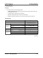
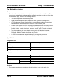
Maintenance Schedule ...................................................................................8
Table of Contents 00
Service Training Mazda5
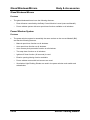
General Information
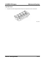
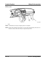
General Information
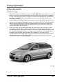
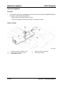
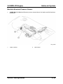
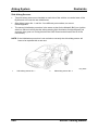
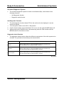
Product Concept
•
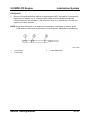
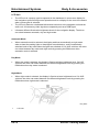
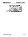
When Mazda began developing its next-generation MAV (Multi Activity Vehicle), it set its
sights on creating a new global standard. It goes without saying that a MAV is intended
to carry a lot of people and a lot of luggage. From this basic premise, we characterized
our MAV as a ‘lifestyle partner’ that enables people to enjoy activities together with
relatives and friends.
•
Given our focus on creating a MAV that enhances communication, we decided to use an
entirely new seven seater packaging concept. In contrast to the ‘5+2’ concept, whereby
space is evenly divided among the five seating positions rear of the front seats, our
‘6+One’ packaging concept provides for the occasional use of one seat, creating more
space for the rest of the occupants.
•
At the same time, we provided the Mazda5 with performance that’s focused on easy,
enjoyable driving and riding, rather than the kind of performance that’s reflected in
overwhelming power. The choice of either a 1.8 liter or 2.0 liter gasoline engine coupled
to a 5-speed manual transmission, or 2.0 liter turbo-diesel engine (in high-power and
standard-power versions) with particulate filter coupled to a six-speed manual
transmission allow the customer to choose between performance and economy. Sporty
chassis performance completes the package, providing a total Zoom-Zoom driving
experience for the driver and passengers.
M5_00001
Service Training Mazda5
00-1
General Information
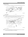
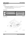
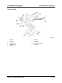
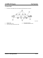
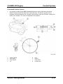
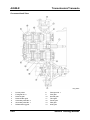
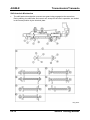
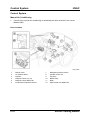
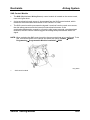
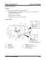
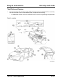
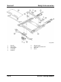
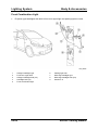
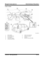
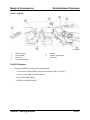
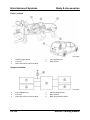
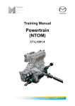
Jacking and Lifting
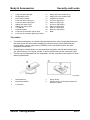
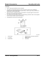
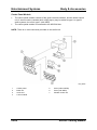
•
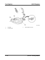
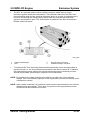
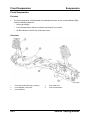
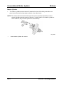
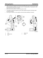
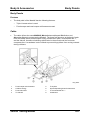
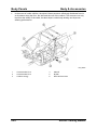
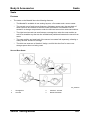
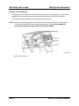
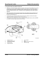
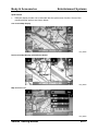
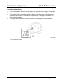
The front of the vehicle can be lifted with a jack near the center of the front crossmember.
M5_00002
1
2
Front crossmember
Jack up position
3
Front
NOTE: To prevent obstruction between the jack body and front bumper when the jack body
is inserted, use a low floor type jack (frame height is 170 mm or less).
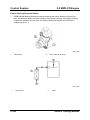
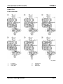
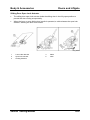
•
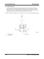
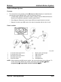
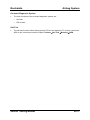
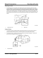
The rear of the vehicle can be lifted with a jack at the center of the rear crossmember.
M5_00003
1
Rear crossmember
NOTE: Place a board (approximately 20 mm {0.78 in} thick) between the rear crossmember
and the jack to prevent damage to the crossmember.
00-2
Service Training Mazda5
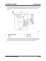
General Information
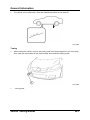
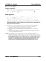
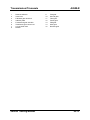
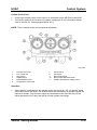
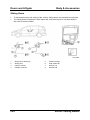
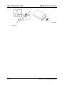
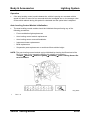
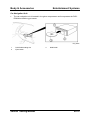
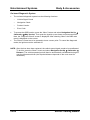
•
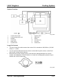
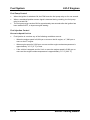
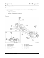
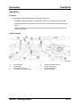
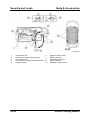
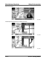
The vehicle can be lifted with a lift at the indicated positions on the side sill.
M5_00004
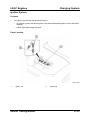
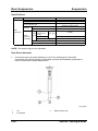
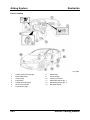
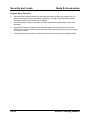
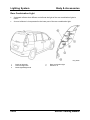
Towing
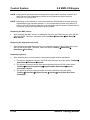
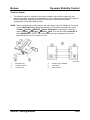
•
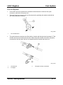
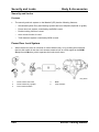
When towing the vehicle, remove the towing eylet from the storage box in the rear cargo
area, open the cap located on the front bumper and install the towing eyelet.
M5_00005
1
Towing eyelet
Service Training Mazda5
00-3
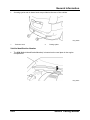
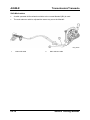
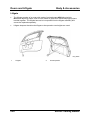
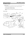
General Information
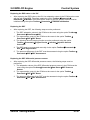
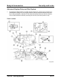
•
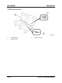
A towing eyelet and tie down hook are provided at the rear of the vehicle.
M5_00006
1
Tie down hook
2
Towing eyelet
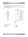
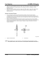
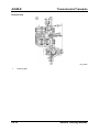
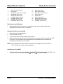
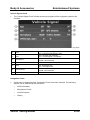
Vehicle Identification Number
•
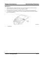
The VIN (Vehicle Identification Number) is located on the cowl plate in the engine
compartment.
M5_00007
00-4
Service Training Mazda5
General Information
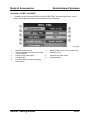
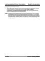
•
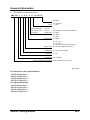
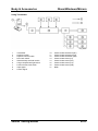
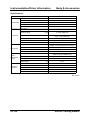
The VIN key is shown as below:
JMZ CR 1 9 8 2 5 # 1 2 3 4 5 6
Serial No.
0 = Hiroshima
Plant 1 = Hofu
For Europe-RHD :
Dummy
0
For Europe-LHD
:
Dummy
5 to 9 (Same as model year-Israel etc.)
For Others
:
Model year
5 = 2005
2 = 5MTX
5 = 4ATX
Transmission 6 = 6MTX
8 = L8 (1.8 L)
F = LF (2.0 L)
T = RF-Turbo-Standard power (2.0 L)
Engine Type R = RF-Turbo-High power (2.0 L)
Body style 9 = 4-door station wagen
Drive axle 1 = FF
Vehicle type CR = Mazda5
World manufacturer indication JMZ = European (L.H.D., U.K.)
M5_00T001
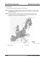
For European (L.H.D.) Specifications
JMZCR1982##100001 ⎯
JMZCR19F2##100001 ⎯
JMZCR19R6##100001 ⎯
JMZCR19T6##100001 ⎯
For UK Specifications
JMZCR19820#100001 ⎯
JMZCR19F20#100001 ⎯
JMZCR19R60#100001 ⎯
JMZCR19T60#100001 ⎯
Service Training Mazda5
00-5
General Information
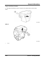
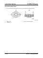
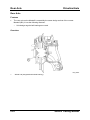
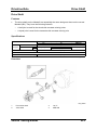
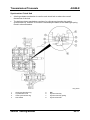
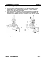
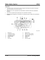
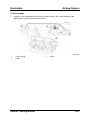
Engine Identification Number
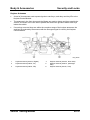
•
The engine identification number is located on the cylinder block as shown below:
L8/LF
M5_00008
MZR-CD
M5_00009
1
00-6
Front
Service Training Mazda5
General Information
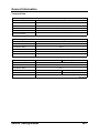
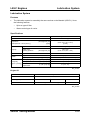
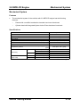
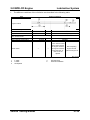
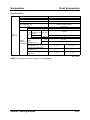
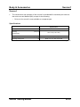
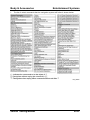
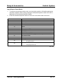
Technical Data
1.8 L MZR Engine
3
Displacement
1798 cm
Bore x Stroke
83 x 83.1 mm
10.8:1
Compression Ratio
Maximum Power
85 kW {115 PS} at 5,300 rpm
Maximum Torque
165 Nm at 4,000 rpm
Euro 4
Emission Standard
2.0 L MZR Engine
3
Displacement
1999 cm
Bore x Stroke
87.5 x 83.1 mm
10.8:1
Compression Ratio
Maximum Power
107kW {145 PS} at 6,000 rpm
Maximum Torque
185 Nm at 4,500 rpm
Euro 4
Emission Standard
2.0 L MZR-CD Engine
Standard Power
High Power
3
Displacement
1998 cm
Bore x Stroke
86 x 86 mm
16.7:1
Compression Ratio
Maximum Power
81 kW {110PS} at 3,500 rpm
Maximum Torque
310 Nm at 2,000 rpm
Emission Standard
105 kW {143 PS} at 3,500 rpm
360 Nm at 2,000 rpm
Euro 4
M5_00T002
Service Training Mazda5
00-7
General Information
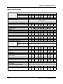
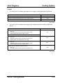
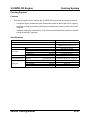
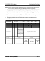
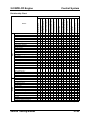
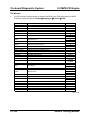
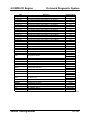
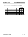
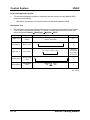
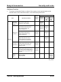
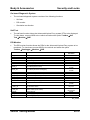
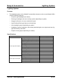
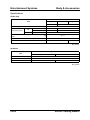
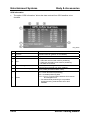
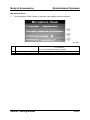
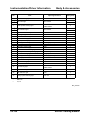
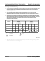
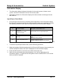
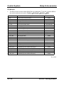
Maintenance Schedule
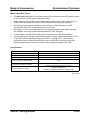
Maintenance Interval (Number of months or km (miles), whichever comes first)
Months
x1000 km
x1000 miles
Maintenance Item
12
20
12.5
24
40
25
36
60
37.5
48
80
50
60
100
62.5
72
120
75
84
140
87.5
96
108
160
180
100 112.5
GASOLINE ENGINE
Audible inspection every 120,000 km (75,000 miles),
if noisy, adjust.
Engine valve clearance
Spark plugs
Air cleaner element
Evaporative system (if installed)
DIESEL ENGINE
Engine valve clearance
Engine timing belt
Fuel filter
Fuel injection system
Fuel system (Drain water)
Air cleaner element
GASOLINE and DIESEL ENGINE
Engine oil *1
Engine oil filter *1
Drive belts
Cooling system/coolant top-up
Replace every 120,000 km (75,000 miles)
R
I
I
R
I
R
I
I
Replace every 120,000 km (75,000 miles)
I
D
C
D
C
R
R
R
R
R
I
D
R
R
R
I
I
D
C
D
C
R
R
R
R
I
R
I
D
R
R
R
I
I
D
C
D
C
R
R
R
R
Replace every 200,000 km (125,000 miles) or 11 years
Others
Replace at first 100,000 km (62,500 miles) or 4 years;
after that, every 2 years
Fuel lines and hoses
Battery electrolyte level and specific gravity
Brake lines, hoses and connections
Brake fluid *3
Parking brake
Disc brakes
Power steering fluid, lines, hoses,
and connections
I
I
I
I
I
R
I
I
I
I
I
I
Steering operation and linkages
Manual transaxle oil
Front and rear suspension and ball joints
I
I
I
I
I
I
I
I
R
I
I
I
I
I
I
I
I
I
I
I
I
R
I
I
I
I
I
I
I
I
I
I
I
I
I
R
I
I
I
I
I
I
I
I
Inspect every 80,000 km (50,000 miles) or 5 years
Drive shaft dust boots
Exhaust system and heat shields
Body condition
(for rust, corrosion and perforation)
Cabin air filter (if installed)
Tires (including spare tire)
(with inflation pressure adjustment)
I
I
I
I
I
R
I
I
I
I
R
R
I
I
FL22 type *2
Engine coolant
R
I
D
R
Inspect annually
R
I
I
R
I
I
R
I
I
R
I
I
I
M5_00T003
00-8
Service Training Mazda5
General Information
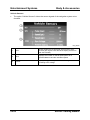
I
R
C
D
•
: Inspect and clean, repair, adjust, or replace if necessary.
: Replace
: Clean
: Drain
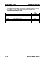
Refer below for a description of items marked * in the maintenance chart.
–
*1: If the vehicle is operated under hard conditions (dusty road, extended periods of
idling or low speed operation, cold temperature or short driving distances), change
the engine oil and oil filter every 10,000 km (6,250 miles) or less.
–
*2: Use FL22 type coolant in vehicles with the inscription “FL22” on the radiator cap
itself or the surrounding area. Use FL22 when replacing the coolant.
–
*3: If the brakes are used extensively (for example, continuous hard driving or
mountain driving) or if the vehicle is operated in extremely humid climates, change
the brake fluid annually.
Service Training Mazda5
00-9
General Information
NOTES:
00-10
Service Training Mazda5
01
Engines
01 Engines
Table of Contents
L8/LF Engines
Mechanical System .............................................................................................1
Features..........................................................................................................1
Specifications..................................................................................................1
Overview .........................................................................................................1
Engine Performance Curve.............................................................................2
Lubrication System .............................................................................................3
Features..........................................................................................................3
Specifications..................................................................................................3
Engine Oil .................................................................................................3
Parts Location .................................................................................................4
Cooling System ...................................................................................................5
Features..........................................................................................................5
Specifications..................................................................................................5
Parts Location .................................................................................................6
System Overview ............................................................................................7
Long Life Coolant............................................................................................7
Cooling Fan.....................................................................................................8
Wiring Diagram ...............................................................................................8
Control ............................................................................................................9
Fail-safe Function .........................................................................................10
Over-current Failsafe ..............................................................................10
Overheat Failsafe ...................................................................................10
Fan Control Module Input Signal Failsafe...............................................10
Intake-air System...............................................................................................11
Features........................................................................................................11
Parts Location ...............................................................................................12
System Overview ..........................................................................................13
Fuel System .......................................................................................................14
Features........................................................................................................14
Specifications................................................................................................14
Parts Location ...............................................................................................15
Fuel Line Removal ........................................................................................17
Fuel Pump Control ........................................................................................18
Fuel Injection Control ....................................................................................18
Excessive Speed Fuel Cut......................................................................18
Exhaust System.................................................................................................19
Features........................................................................................................19
Table of Contents 01
Service Training Mazda5
01 Engines
Table of Contents (continued)
Emission System...............................................................................................20
Features........................................................................................................20
Parts Location ...............................................................................................20
Charging System...............................................................................................22
Features........................................................................................................22
Specifications................................................................................................22
Parts Location ...............................................................................................22
Ignition System..................................................................................................23
Features........................................................................................................23
Parts Location ...............................................................................................23
Ignition Coil ...................................................................................................24
Control System..................................................................................................25
Features........................................................................................................25
Specifications................................................................................................25
Parts Location ...............................................................................................26
System Overview ..........................................................................................27
Relationship Chart ........................................................................................28
2.0 MZR-CD Engine
Mechanical System ...........................................................................................29
Features........................................................................................................29
Specifications................................................................................................29
Engine Performance Curve...........................................................................30
Overview .......................................................................................................31
Pistons ...............................................................................................................32
Cylinder Head ....................................................................................................33
Lubrication System ...........................................................................................34
Features........................................................................................................34
Specifications................................................................................................34
Engine Oil ...............................................................................................34
Parts Location ...............................................................................................35
Engine Oil...........................................................................................................36
Oil Dipstick ....................................................................................................37
Oil Dilution Calculation ..................................................................................38
Oil Cooler and Oil Filter ........................................................................................
Service Training Mazda5
Table of Contents 01
01 Engines
Table of Contents (continued)
Cooling System .................................................................................................40
Features........................................................................................................41
Specifications................................................................................................41
Parts Location ...............................................................................................42
Intake-air System...............................................................................................43
Features........................................................................................................43
Parts Location ...............................................................................................43
Turbocharger .....................................................................................................44
Manifold Absolute Pressure Sensor................................................................45
Fuel System .......................................................................................................46
Features........................................................................................................46
Parts Location ...............................................................................................46
Common Rail .....................................................................................................47
Injectors .............................................................................................................48
Injector Correction Factors............................................................................50
Injection Amount Learning Function..............................................................51
Emission System...............................................................................................52
Parts Location ...............................................................................................52
Exhaust System.................................................................................................53
Features........................................................................................................53
Parts Location ...............................................................................................53
Exhaust Gas Recirculation System .................................................................54
Features........................................................................................................54
EGR Valve ....................................................................................................54
EGR Cooler...................................................................................................57
Intake Shutter Valve......................................................................................58
Diesel Particulate Filter System .......................................................................61
Features........................................................................................................61
Diesel Particulates ........................................................................................61
Diesel Particulate Filter .................................................................................62
DPF Differential Pressure Sensor .................................................................65
Diagnostics .............................................................................................68
Exhaust Gas Temperature Sensors..............................................................70
Heated Oxygen Sensor.................................................................................72
DPF Indicator Light .......................................................................................75
Regeneration Control ....................................................................................76
Soot Amount Calculation ........................................................................76
Regeneration Process ............................................................................78
Regeneration Intervals............................................................................79
Table of Contents 01
Service Training Mazda5
01 Engines
Table of Contents (continued)
Charging System...............................................................................................80
Features........................................................................................................80
Specifications................................................................................................80
Parts Location ...............................................................................................80
Smart Charging System....................................................................................81
Control System..................................................................................................83
Features........................................................................................................83
Parts Location ...............................................................................................83
Relationship Chart ........................................................................................85
Powertrain Control Module............................................................................86
Crankshaft Position Sensor...........................................................................87
Camshaft Position Sensor.............................................................................89
Accelerator Pedal Position Sensor................................................................91
Power Steering Pressure Switch...................................................................94
Maintenance and Repair ...............................................................................95
Replacing the engine oil .........................................................................95
Manual regeneration...............................................................................95
Replacing the MAF sensor .....................................................................96
Replacing the high-pressure pump .........................................................96
Replacing injectors .................................................................................96
Replacing the EGR valve or the ISV.......................................................97
Replacing the DPF..................................................................................97
Replacing the DPF differential pressure sensor .....................................97
Replacing the HO2S ...............................................................................98
Replacing the PCM.................................................................................98
On-board Diagnostic System ...........................................................................99
Features........................................................................................................99
Self Test........................................................................................................99
PID Monitor .................................................................................................100
Simulation Test ...........................................................................................103
Service Training Mazda5
Table of Contents 01
NOTES:
Table of Contents 01
Service Training Mazda5
L8/LF Engines
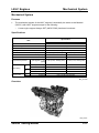
Mechanical System
Mechanical System
Features
•
The mechanical system of the L8/LF engines is essentially the same as the Mazda6
(GG/GY) with L8/LF engines except for the following:
–
A new engine support hanger SST (49C0175AO) has been introduced.
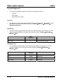
Specifications
Specification
Item
L8
Type
Cylinder arrangement and number
Combustion chamber
Valve system
Displacement
(ml {cc, cu in})
Bore x stroke
(mm {in})
Compression ratio
Compression pressure
IN
Valve timing
EX
Valve clearance
(engine cold)
IN
EX
LF
Gasoline 4-stroke
Inline, 4-cylinder
Pentroof
DOHC, Timing chain driven, 16 valves
1,798 {1,798, 109.7}
83 x 83.1
10.8
(kPa {kgf/cm 2 , psi}
1,750 {17.85, 253.82} [300]
[rpm])
Open BTDC (°)
Close ABDC (°)
Open BBDC (°)
Close ATDC (°)
(mm {in})
(mm {in})
1,999 {1,999, 122}
87.5 x 83.1
10.8
1,720 {17.54, 249.5} [300]
4
33
37
4
4
52
37
4
0.22-0.28 {0.0087-0.0110}
0.27-0.33 {0.0107-0.0129}
M5_01T018
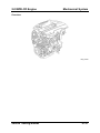
Overview
M5_01017
Service Training Mazda5
01-1
Mechanical System
L8/LF Engines
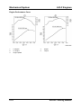
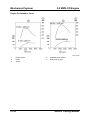
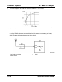
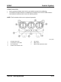
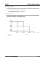
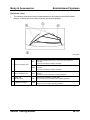
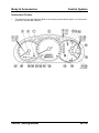
Engine Performance Curve
M501T066
1
2
3
01-2
L8 engine
LF engine
Engine speed
4
5
Output
Torque
Service Training Mazda5
L8/LF Engines
Lubrication System
Lubrication System
Features
•
The lubrication system is essentially the same as that on the Mazda6 (GG/GY). It has
the following features:
–
–
Spin-on type oil filter.
Water-cooled type oil cooler.
Specifications
Item
Specification
Force-fed type
Type
Oil pressure
[oil temperature: 100°C {212°F}]
(kPa {kgf/cm2, psi}
[rpm])
234—521
{2.39—5.31, 33.9—75.5}
[3,000]
Type
Oil pump
Relief valve
opening pressure
Oil Cooler
Type
Type
Oil filter
Bypass pressure
Total (dry engine)
Oil replacement
Oil capacity
(approx. quantity) Oil and oil filter
replacement
Trochoid gear type
(kPa {kgf/cm2, psi}
(kPa {kgf/cm2, psi})
(L {US qt, Imp qt})
(L {US qt, Imp qt})
450—550
{4.59—5.61,65.3—79.8}
Water-cooled
Full-flow, paper element
80— 120 {0.82— 1.22, 11.6—17.4}
4.6 {4.8, 4.0}
3.9 {4.1, 3.4}
(L {US qt, Imp qt})
4.3 {4.5, 3.8}
M5_01T001
Engine Oil
Specification
Item
API SL, ACEA A3
Grade
Viscosity (SAE)
Remarks
5W – 30
10W – 40
Mazda genuine Dexelia oil e.g.
5W – 20
–
M5_01T002
Service Training Mazda5
01-3
Lubrication System
L8/LF Engines
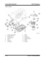
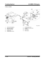
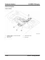
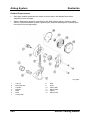
Parts Location
M5_01001
1
2
3
4
5
6
7
8
01-4
Oil pump chain tensioner
Oil pump chain guide
Oil pump chain
Oil pump sprocket
Oil pump
O-ring
Oil strainer
Oil drain plug
9
10
11
12
13
14
15
16
Washer
Oil pan
Oil jet valve
Oil filter adapter
Oil pressure switch
Oil filter
Gasket
Oil cooler
Service Training Mazda5
L8/LF Engines
Cooling System
Cooling System
Features
•
The cooling system has the following features:
–
Cooling system pressure cap has been moved from the coolant reserve tank to the
cooling system filler neck.
–
–
–
A long-life engine coolant has been introduced.
Separate cooling system filler neck has been introduced.
Stepless cooling fan controlled by a fan control module has been introduced.
Specifications
Item
Type
Coolant capacity (approx. quantity)
Water pump
Thermostat
Radiator
Cooling system
cap
Cooling fan
Type
Type
Opening
temperature
Full-open temperature
Full-open lift
Type
Cap valve opening
pressure
Type
Number of blades
Outer diameter
Fan motor output
(L {US qt, lmp qt})
Specification
Water-cooled, Electromotive
With heater: 7.0 {7.4, 6.2}
Without heater: 6.5 {6.9, 5.7}
Centrifugal, V-ribbed belt-driven
Wax, bottom-bypass
(°C {°F})
80—84 {176—183}
(° C {° F})
(mm {in})
97 {207}
8.0 {0.31} or more
Corrugated fin
(kPa {kgf/cm 2 , psi})
(mm {in})
(W)
93.2—122.6 {0.95—1.25, 13.5—17.8}
Electric
7
360 {14.2}
240
M5_01T003
Service Training Mazda5
01-5
Cooling System
L8/LF Engines
Parts Location
M5_01002
1
2
3
4
5
6
01-6
Cooling system cap
Coolant reserve tank
Cooling system filler neck
Radiator
Thermostat
Water pump
7
8
9
10
11
Cooling fan assembly
Cooling fan
Radiator cowling
Cooling fan motor
Fan control module
Service Training Mazda5
L8/LF Engines
Cooling System
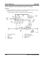
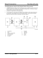
System Overview
M5_01003
1
2
3
4
5
6
Coolant reserve tank
Cooling system filler neck
Radiator
Thermostat
Water pump
Cylinder block
7
8
9
10
11
12
Cylinder head
EGR valve
Heater
Oil cooler (AT)
Oil cooler
Coolant flow
Long Life Coolant
•
The use of long life coolant means that coolant life is extended to 200,000 km (125,000
miles) or 11 years.
•
It is not recommended that normal coolant is mixed with long life coolant, as the life of
the long life coolant will be reduced.
•
Because the long life coolant is green, and therefore indistinguishable from normal
coolant, the designation ‘FL22’ is written on or near the cooling system pressure cap to
indicate the correct coolant type.
M5_01004
Service Training Mazda5
01-7
Cooling System
L8/LF Engines
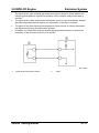
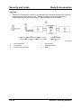
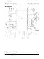
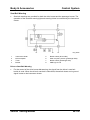
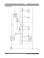
Cooling Fan
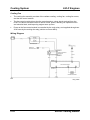
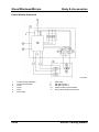
•
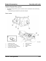
The cooling fan assembly consists of the radiator cowling, cooling fan, cooling fan motor,
and the fan control module.
•
The fan control module drives the fan motor based on a duty signal received from the
PCM. This allows variable control of the fan motor speed, reducing fan operation noise
and electrical load, and improving engine warm up time.
•
Power to the fan control module is controlled by the main relay, and supplied through two
30 A fuses by the cooling fan relay (similar to current MPV).
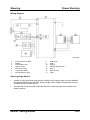
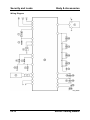
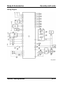
Wiring Diagram
M5_01005
01-8
Service Training Mazda5
L8/LF Engines
Cooling System
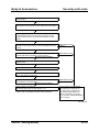
Control
•
The cooling fan is controlled according to the engine coolant temperature as follows :
Conditions
Duty ratio
• Engine coolant temperature is less than 100 ° C {212 ° F}.
0%
• Engine coolant temperature is 106—108 ° C {223—226 ° F}.
75%
• Engine coolant temperature is 108 ° C {226 ° F} or more.
100%
M5_01T004
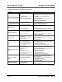
•
The cooling fan is controlled according to the refrigerant pressure switch condition as
follows:
Conditions
• When all of the following conditions are met:
— A/C is on.
— Refrigerant pressure switch (medium pressure) is off.
— Vehicle speed is 85 km/h {53 mph} or more.
Duty ratio
0%
• A/C is off.
• When all of the following conditions are met:
— A/C is on.
— Refrigerant pressure switch (medium pressure) is off.
— Vehicle speed is 45—85 km/h {28—52 mph}.
60%
• When all of the following conditions are met:
— A/C is on.
— Refrigerant pressure switch (medium pressure) is off.
— Vehicle speed is 45 km/h {27 mph} or less.
65%
• When all of the following conditions are met:
— A/C is on.
— Refrigerant pressure switch (medium pressure) is on.
75%
M5_01T005
Service Training Mazda5
01-9
Cooling System
L8/LF Engines
Fail-safe Function
Over-current Failsafe
•
If current to the fan motor exceeds a specified value, the fan control module stops the
fan motor for a specified amount of time.
Overheat Failsafe
•
If the internal temperature of the fan module exceeds a specified value, the fan control
module operates the cooling fan at high speed. If the temperature continues to rise, the
cooling fan is switched off (normal cooling fan control will be resumed by switching the
ignition switch OFF and then ON again).
Fan Control Module Input Signal Failsafe
•
If the voltage at input signal terminal from the fan control module remains low or high, the
module determines that the fan control circuit has a malfunction and will operate the fan
at high speed.
01-10
Service Training Mazda5
L8/LF Engines
Intake-air System
Intake-air System
Features
•
The intake-air system is essentially the same as that on the current Mazda3 (BK) with LF
engine. It has the following features:
–
–
–
Variable intake air system is used (LF engines only).
–
Plastic intake manifold is used.
Variable tumble control system is used.
Two resonance chambers, one near the fresh-air duct and one near the air cleaner
are used.
Service Training Mazda5
01-11
Intake-air System
L8/LF Engines
Parts Location
M5_01070
1
2
Fresh-air duct
Resonance chamber (fresh-air duct side)
8
9
3
4
5
6
7
Air cleaner
Resonance chamber (air cleaner side)
Throttle body
IAC valve
Variable intake air solenoid valve (LF
engine)
10
11
12
13
01-12
Variable tumble solenoid valve
Variable intake air shutter valve actuator
(LF engine)
Variable tumble shutter valve actuator
Intake manifold
Accelerator cable
Accelerator pedal
Service Training Mazda5
L8/LF Engines
Intake-air System
System Overview
M5_01071
1
Air cleaner
9
2
Resonance chamber (fresh-air duct side)
10
3
4
5
6
7
8
Resonance chamber (air cleaner side)
IAC valve
Throttle body
Vacuum chamber
Check valve
Variable intake air solenoid valve (LF
engine)
11
12
13
14
15
Service Training Mazda5
Variable intake air shutter valve actuator
(LF engine)
Variable intake air shutter valve (LF
engine)
Variable tumble solenoid valve
Variable tumble shutter valve actuator
Variable tumble shutter valve
Intake manifold
To Powertrain Control Module
01-13
Fuel System
L8/LF Engines
Fuel System
Features
•
The fuel system is essentially the same as that used on the current Mazda3 (BK) except
for the following:
–
–
–
Steel fuel tank is used.
–
–
Quick connectors attaching the fuel hoses to the fuel tank have been changed.
Fuel pump unit can be removed through access hole under second row seats.
Fuel pump unit can be disassembled and individual components replaced (fuel pump
motor, fuel gauge sender, low pressure filter, pressure regulator).
New SST for quick connector removal has been established.
Specifications
Item
Injector
Specifications
Type
Hi-ohmic
Type of fuel delivery
Top-feed
Type of drive
Voltage
Pressure
regulator
Regulating pressure
(approximately)
(kPa {kgf/cm 2 , psi})
390 {3.98, 56.6}
Fuel tank
Capacity
(L {US gal, lmp gal})
60 {16, 13}
Fuel pump
Type
Fuel
Quality
Electric
Premium unleaded fuel
(Research octane number is
95 or more (conforming to EN228)
M5_01T006
01-14
Service Training Mazda5
L8/LF Engines
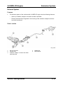
Fuel System
Parts Location
M5_01007
1
2
Fuel injector
Quick release connectors
Service Training Mazda5
3
4
Main fuse block
Fuel pump relay
01-15
Fuel System
L8/LF Engines
M5_01008
1
2
Fuel tank
Fuel pump unit
01-16
3
Quick release connector
Service Training Mazda5
L8/LF Engines
Fuel System
Fuel Line Removal
•
A new SST has been introduced to enable the disconnection of the fuel line quick
connector used at the fuel pump unit..
•
The quick release connector can be disconnected by pinching the retainer tab with the
SST and pulling the connector.
M5_01009
1
•
SST 49 E042 001
The quick release connectors are fitted with a checker tab that prevents improper fit. This
checker tab cannot normally be removed. When the quick release connector is properly
connected to the fuel pipe, the lock is released and the checker tab comes off.
M5_01010
1
2
Checker tab
Fuel pipe
Service Training Mazda5
3
Fuel pipe correctly connected
01-17
Fuel System
L8/LF Engines
Fuel Pump Control
•
When the ignition is switched ON, the PCM turns the fuel pump relay on for one second.
•
When a crankshaft position sensor signal is detected during cranking, the fuel pump
relay is turned ON.
•
The fuel pump relay remains ON for approximately two seconds after the ignition has
been switched OFF, to improve engine starting.
Fuel Injection Control
Excessive Speed Fuel Cut
•
Fuel injection is cut when any of the following conditions are met:
–
When the engine speed is 6,800 rpm or more on the L8 engine, or 7,000 rpm or
more on the LF engine.
–
When engine speed is 5,500 rpm or more and the engine coolant temperature is
approximately -15 °C {5 °F} or less.
–
If the vehicle is stopped, and for 2 min or more the engine speed is 5,000 rpm or
more and the engine coolant temperature is approximately 117 °C {243 °F}.
01-18
Service Training Mazda5
L8/LF Engines
Exhaust System
Exhaust System
Features
•
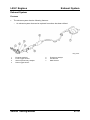
The exhaust system has the following features:
–
An exhaust system that can be replaced in sections has been utilized.
M5_01011
1
2
3
4
Exhaust manifold
Front oxygen sensor
Warm-up three-way-catalyst
Rear oxygen sensor
Service Training Mazda5
5
6
7
Three-way-catalyst
Pre-silencer
Main silencer
01-19
Emission System
L8/LF Engines
Emission System
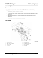
Features
•
The emission system on the Mazda5 is the same as that of the current Mazda3 (BK) with
LF engine. It has the following features:
–
–
Exhaust gas recirculation system is used.
Three-way catalytic converter with warm-up converter is used.
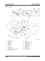
Parts Location
M5_01067
1
2
3
Positive crankcase ventilation valve
Exhaust gas recirculation valve
Purge solenoid valve
01-20
4
5
Warm-up three-way catalyst
Three-way catalyst
Service Training Mazda5
L8/LF Engines
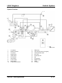
Emission System
Fuel Tank
M5_01068
1
2
3
Fuel filler cap
Charcoal canister
Evaporative chamber
Service Training Mazda5
4
5
Check valve (two-way)
Rollover valve
01-21
Ignition System
L8/LF Engines
Charging System
Features
•
The charging system on the Mazda5 is the same as that of the current Mazda3 (BK) with
LF engine. It has the following features:
–
–
A non-regulator type generator with built-in power transistor is used.
Cooling duct is provided for the battery.
Specifications
Item
Voltage
Battery
Type and capacity
(5-hour rate)
Output
Generator Regulated voltage
Self diagnosis function
Specifications
12
(V)
(A·h)
50D20L (40), 75D26L (52),
(V-A)
12-90
Controlled by PCM
M5_01T020
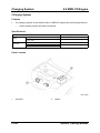
Parts Location
M5_01069
1
Battery
01-22
2
Generator
Service Training Mazda5
L8/LF Engines
Charging System
Ignition System
Features
•
The ignition system has the following features:
–
An ignition system with direct ignition coils and independent ignition control has been
adopted.
–
Iridium type spark plugs are used.
Parts Location
M5_01013
1
Ignition coil
Service Training Mazda5
2
Spark plug
01-23
Ignition System
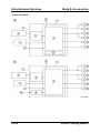
L8/LF Engines
Ignition Coils
•
Ignition coils installed directly to each spark plug have been adopted.
•
The direct ignition coil consists of an ignition coil with integrated power transistor, ignition
coil connector, and rubber boot.
•
Construction of the ignition coils is essentially the same as those on the current Mazda3
(BK) with ZJ/Z6 engine.
M5_01014
1
2
3
4
5
6
Ignition coil external view
Ignition coil
Ignition coil electrical circuit
PCM
Cylinder number
No. 1
01-24
7
8
9
10
11
12
No. 2
No. 3
No. 4
Capacitor
Ignition switch
Battery
Service Training Mazda5
L8/LF Engines
Control System
Control System
Features
•
The engine control system is essentially the same as that of the Mazda3 (BK) with LF
engine.
Specifications
Item
Neutral switch
Specification
ON/OFF
CPP switch
ON/OFF
ECT sensor
Thermistor
IAT sensor (inside MAF)
Thermistor
TP sensor
MAF sensor
Potentiometer
Hot-wire
Front HO2S
Zirconia element (Stoichiometric air/fuel ratio sensor)
Rear HO2S
Zirconia element (Stoichiometric air/fuel ratio sensor)
BARO sensor (built into PCM)
Piezoelectric element
KS
Piezoelectric element
MAP sensor
Piezoelectric element
CKP sensor
Magnetic pickup
CMP sensor
Magnetic pickup
Brake switch
ON/OFF
M5_01T019
Service Training Mazda5
01-25
Control System
L8/LF Engines
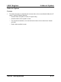
Parts Location
M5_01015
1
2
3
4
5
6
7
8
9
10
MAF/IAT sensor
TP sensor
IAC valve
MAP sensor
CKP sensor
KS
Fuel injector
CMP sensor
VIS solenoid valve (LF engine)
VTCS solenoid valve
01-26
11
12
13
14
15
16
17
18
19
PCM
Purge solenoid valve
EGR valve
Neutral switch (MT)
TR switch (AT)
HO2S (front, rear)
ECT sensor
Brake switch
CPP switch (MT)
Service Training Mazda5
L8/LF Engines
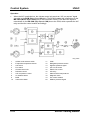
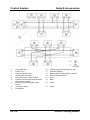
Control System
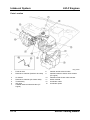
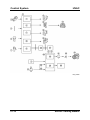
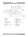
System Overview
M5_01016
1
2
3
4
5
6
7
8
9
10
Air cleaner
MAF/IAT sensor
TP sensor
MAP sensor
CMP sensor
ECT sensor
CKP sensor
Front H O2S
Rear HO2S
Purge solenoid valve
Service Training Mazda5
11
12
13
14
15
16
17
18
19
20
EGR valve
VIS solenoid valve (LF engine)
VTCS solenoid valve
IAC valve
Fuel pump unit
KS
Fuel injector
BARO sensor
PCM
To PCM
01-27
Control System
L8/LF Engines
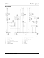
Refrigerant pressure switch
(medium pressure)
Battery voltage
Generator (terminal P: stator coil)
Vehicle speed signal
Instrument cluster
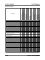
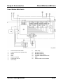
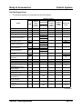
Output
IAC valve
VIS solenoid valve
VTCS solenoid valve
Fuel injectors
Fuel pump relay
Ignition coil
EGR valve
Purge solenoid valve
Front HO2S heater
Rear HO2S heater
A/C relay
Fan control module
Starter relay
Generator (terminal D: field coil)
01-28
x
x
x
x
x
x
x
x
x
x
x
x
x
x
x
x
x
x
x
x
x
x
x
x
x
Generator control
x
x
Immobiliser system
x
x
x
x
x
x
x
Electrical fan control
x
x
A/C cut-off control
Fuel pump control
x
x
x
x
Rear HO2S heater control
x
x
x
x
Front HO2S heater control
x
Fuel injection control
Variable tumble control system
x
Purge control
x
x
x
x
x
x
x
x
x
EGR control
x
x
x
x
x
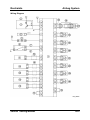
Electronic spark advance (ESA) control
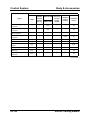
Input
IAT sensor
MAF sensor
TP sensor
MAP sensor
ECT sensor
CMP sensor
CKP sensor
KS
Front HO2S
Rear HO2S
BARO sensor
Neutral switch
CPP switch
Brake switch
A/C on request signal, refrigerant pressure
switch (high, low pressure)
Variable intake-air system
Component
Idle air control (IAC)
Relationship Chart
x
x
x
x
x
x
x
x
x
x
x
x
x
x
x
x
x
x
x
x
x
x
x
x
x
x
x
x
x
x
x
x
x
x
x
x
x
x
x
x
x
M5_01T007
Service Training Mazda5
2.0 MZR-CD Engine
Mechanical System
Mechanical System
Features
•
The mechanical system of the vehicles with 2.0 MZR-CD engine has the following
features:
–
–
Pistons with a modified combustion chamber have been introduced.
Cylinder head with integrated injector leak-off lines has been introduced.
Specifications
Item
Type
Cylinder arrangement and number
Combustion chamber
Valve system
Displacement
Bore x stroke
Compression ratio
(kPa {kgf/cm2, psi}
[rpm])
Compression pressure
IN
Valve timing
EX
Valve clearance
(engine cold)
(ml {cc, cu in})
(mm {in})
IN
EX
Service Training Mazda5
Open BTDC (°)
Close ABDC (°)
Open BBDC (°)
Close ATDC (°)
(mm {in})
(mm {in})
Specification
Diesel 4-stroke
Inline, 4-cylinder
Direct injection
SOHC, belt driven, 16-valve
1,998 {1,988, 122.9}
86.0 x 86.0 {3.39 x 3.39}
16.7
2,900 {29.6, 420.7} [250]
6
30
41
8
0.12-0.18 {0.0048-0.0070}
0.32-0.38 {0.0126-0.0149}
M5_01T008
01-29
Mechanical System
2.0 MZR-CD Engine
Engine Performance Curve
M5_01018
1
2
3
Engine speed
Power
Torque
01-30
4
5
Standard power engine
High power engine
Service Training Mazda5
2.0 MZR-CD Engine
Mechanical System
Overview
M5_01019
Service Training Mazda5
01-31
Mechanical System
2.0 MZR-CD Engine
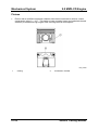
Pistons
•
Pistons with a modified combustion chamber have been introduced to achieve a lower
compression ratio of ε = 16.7 . This leads to lower pumping losses and optimized thermal
efficiency at middle and high engine load, reducing the fuel consumption.
M5_01020
1
Coating
01-32
2
Combustion chamber
Service Training Mazda5
2.0 MZR-CD Engine
Mechanical System
Cylinder Head
•
A cylinder head with integrated leak-off lines for the injectors has been introduced.
M5_01021
Service Training Mazda5
01-33
Lubrication System
2.0 MZR-CD Engine
Lubrication System
Features
•
The lubrication system of the vehicles with 2.0 MZR-CD engine has the following
features:
–
–
–
An engine oil with reduced ash content has been introduced.
An oil dipstick with an additional “X” mark has been introduced.
Oil cooler and oil filter located at the rear of the engine have been introduced.
Specifications
Item
Type
Oil pressure (reference value)
[oil temperature: 100 °C {212 °F}]
Type
Oil pump Relief valve opening pressure
(reference value)
Type
Oil cooler
Type
Oil filter
Bypass pressure
Oil capacity Total (dry engine)
(approx.
Oil replacement
quantity)
Oil and oil filter replacement
(kPa {kgf/cm2, psi}
[rpm])
(kPa {kgf/cm2, psi}
[rpm])
(kPa {kgf/cm2, psi})
(L {US qt, lmp qt})
(L {US qt, lmp qt})
(L {US qt, lmp qt})
Specification
Force-fed type
147 {1.5, 21} min. [1,000]
343 {3.5, 50} min. [3,000]
Trochoid gear type
580-700 {5.9-7.1, 84.1-101.5} [3,000]
Water-cooled
Full-flow, paper element
78-118 {0.8-1.2, 11.3-17.1}
5.5 {5.8, 4.8}
4.9 {5.2, 4.3}
5.1 {5.4, 4.5}
M5_01T009
Engine Oil
Item
Grade
Viscosity
Recommended oil
Specification
ACEA C1 or JASO DL-1
SAE 5W-30
e.g. Mazda genuine Dexelia DPF
M5_01T010
01-34
Service Training Mazda5
2.0 MZR-CD Engine
Lubrication System
Parts Location
M5_01022
1
2
3
4
5
6
Oil filter
Oil cooler
O-ring
Oil jet valve
Oil drain plug
Washer
Service Training Mazda5
7
8
9
10
11
Oil pan
Oil strainer
Gasket
Oil pressure switch
Oil pump
01-35
Lubrication System
2.0 MZR-CD Engine
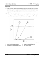
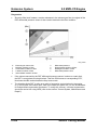
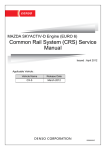
Engine Oil
•
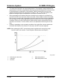
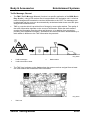
In order to limit the ash amount accumulated in the diesel particulate filter, an engine oil
with reduced ash content is required. This oil must meet the specification ACEA C1
(equivalent to the Japanese specification JASO DL-1) and is also termed as low SAPS
(Sulphate Ash, Phosphor, Sulphur) oil, since it has a reduced proportion of these
components.
NOTE: The use of engine oil with a higher ash content is strictly forbidden as this can lead to
blockage of the DPF. In addition, the usable filter volume is reduced significantly due
to the ash amount deposited in the DPF. As a result, the regeneration intervals are
shortened, so that the fuel consumption and hence the oil dilution are increased.
M5_01058
X
1
2
Service life of DPF
Normal engine oil (ACEA A3/B3/B4)
Conventional low SAPS oil (ACEA C2/C3)
01-36
Y
3
4
Ash amount in the DPF
Mazda low SAPS oil (ACEA C1)
DPF blocked with ash
Service Training Mazda5
2.0 MZR-CD Engine
Lubrication System
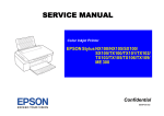
Oil Dipstick
•
Since the fuel post-injections required to regenerate the DPF can lead to an excessively
high engine oil dilution, an “X” mark has been added to the oil dipstick to make the
customer aware of this condition. If the oil level is close to or exceeds the “X” mark, the
engine oil must be replaced.
NOTE: Every time the engine oil is replaced, the parameter “Calculated oil dilution” in the
PCM must be reset (refer to the section “Control System, Maintenance and Repair”).
M5_01023
1
2
L mark (Low)
F mark (Full)
Service Training Mazda5
3
X mark (Excessive)
01-37
Lubrication System
2.0 MZR-CD Engine
Oil Dilution Calculation
•
The PCM calculates the oil dilution amount based on the duration of the regeneration
process and the regeneration intervals.
•
If the engine oil level reaches a certain limit due to oil dilution, DTC P252F is stored in
the PCM but no warning light is illuminated. This DTC comes up when the regeneration
of the DPF has been started multiple times but could never be completed due to the
driving method (such as frequent short distance driving with low engine speed etc.). In
this case, check the engine oil level. If the oil level is lower than the “X” mark on the
dipstick, delete the DTC. In addition, the customer must be informed to change the
driving method (such as driving the vehicle at middle or high engine speeds for a longer
distance), so that regeneration of the DPF is enabled.
•
If the engine oil performance and engine oil level is approaching the limit due to oil
dilution, the DPF indicator light flashes and DTC P253F is stored in the PCM. In addition,
the PCM reduces the fuel injection amount to protect the engine. However, the engine
could be damaged if the vehicle continues to be driven. In this case, replace the engine
oil even if the engine oil level is lower than the “X” mark on the dipstick. In addition, the
customer must be informed to change the driving method (such as driving the vehicle at
middle or high engine speeds for a longer distance), so that regeneration of the DPF is
enabled.
01-38
Service Training Mazda5
2.0 MZR-CD Engine
•
Lubrication System
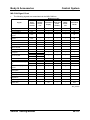
The different conditions of the oil dilution are described in the following table.
Engine oil dilution
Item
Engine oil level
DPF indicator light
—
—
Flashes every 0.4 s
MIL
—
—
—
Output restriction
—
—
Max. 150 km/h (93 mph)
P252F
DTC stored in PCM
Customer action
DPF automatic regeneration
Dealer action
P253F
—
Enabled
—
—
—
Bring the vehicle to a dealer
Disabled
If DTC 253F is stored
in the PCM, replace
the engine oil even if
After inspecting
the engine oil level is
engine oil level
lower than the "X" replace the engine oil.
mark on the oil
dipstick.
M5_01T011
1
2
3
F mark
X mark
Oil dipstick
Service Training Mazda5
4
5
Oil level okay
Oil level excessive
01-39
Lubrication System
2.0 MZR-CD Engine
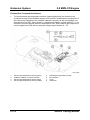
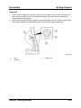
Oil Cooler and Oil Filter
•
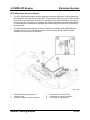
An oil cooler and oil filter located at the rear of the engine have been introduced.
M5_01024
1
2
External view
Cut-view A-A
01-40
3
Engine coolant flow direction
Service Training Mazda5
2.0 MZR-CD Engine
Cooling System
Cooling System
Features
•
The cooling system of the vehicles with 2.0 MZR-CD engine has the following features:
–
–
A long-life engine coolant has been introduced (similar to that of the L8/LF engines).
–
Stepless cooling fan controlled by a fan control module has been introduced (similar
to that of the L8/LF engines).
Separate cooling system filler neck has been introduced (similar to that of the L8/LF
engines).
Specifications
Item
Type
Coolant capacity (approx. quantity)
W ater pump
Thermostat
Radiator
Cooling system cap
Cooling fan
Type
Type
Opening temperature
Full-open temperature
Full-open lift
Type
Cap valve opening
pressure
Type
Number of blades
Outer diameter
Fan motor output
(L {US qt, lmp qt})
(°C {°F})
(°C {°F})
(mm {in})
(kPa {kgf/cm2, psi})
(mm {in})
(W)
Specification
Water-cooled, Electromotive
With heater: 8.5 {9.0, 7.5}
Without heater: 8.0 {8.5, 7.0}
Centrifugal, Timing belt-driven
Wax, bottom-bypass
80-84 {176-183}
95 {203}
8.5 {0.33} or more
Corrugated fin
93.2-122.6 {0.95-1.25, 13.5-17.8}
Electric
7
360 {14.2}
240
M5_01T012
Service Training Mazda5
01-41
Cooling System
2.0 MZR-CD Engine
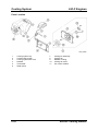
Parts Location
M5_01025
1
2
3
4
5
6
Cooling fan assembly
Fan control module
Radiator cowling
Cooling fan motor
Cooling fan
Coolant reserve tank
01-42
7
8
9
10
11
Cooling system cap
Cooling system filler neck
Radiator
Thermostat
Water pump
Service Training Mazda5
2.0 MZR-CD Engine
Intake-air System
Intake-air System
Features
•
The intake-air system of the vehicles with 2.0 MZR-CD engine has the following
features:
–
–
MAF learning function has been cancelled.
–
Manifold absolute pressure sensor located above the intake manifold has been
introduced.
–
Variable swirl control valves have been cancelled.
Turbocharger with variable geometry turbine and reduced turbine diameter has been
introduced.
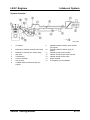
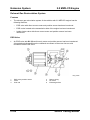
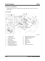
Parts Location
M5_01026
1
2
3
4
Glow plug lead
VBC vacuum actuator
Turbocharger
Air cleaner
Service Training Mazda5
5
6
7
8
Charge-air cooler
Charge-air cooler duct
Intake manifold
Glow plug
01-43
Intake-air System
2.0 MZR-CD Engine
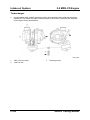
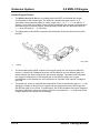
Turbocharger
•
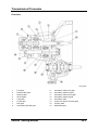
A turbocharger with variable geometry turbine and reduced turbine diameter has been
introduced. This leads to a lower inertia moment of the turbine, improving the response
of the engine during acceleration.
M5_01027
1
2
VBC vacuum actuator
Intake air flow
01-44
3
Exhaust gas flow
Service Training Mazda5
2.0 MZR-CD Engine
Intake-air System
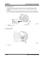
Manifold Absolute Pressure Sensor
•
A MAP (Manifold Absolute Pressure) sensor located above the intake manifold has been
introduced.
M5_01059
1
Intake manifold
Service Training Mazda5
2
MAP sensor
01-45
Fuel System
2.0 MZR-CD Engine
Fuel System
Features
•
The fuel system of the vehicles with 2.0 MZR-CD engine has the following features:
–
–
–
–
Common rail located above the intake manifold has been introduced.
Solenoid valve-type injectors with injector correction factors have been introduced.
Injector driver module has been cancelled.
Injection amount learning function has been modified.
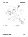
Parts Location
M5_01028
A
1
2
3
4
LHD
Fuel warmer
Priming pump
Fuel filter
Fuel injector
01-46
B
5
6
7
8
RHD
Pressure limiter valve
Common rail
Fuel metering valve
High-pressure pump
Service Training Mazda5
2.0 MZR-CD Engine
Fuel System
Common Rail
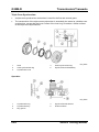
•
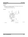
A common rail located above the intake manifold has been introduced.
M5_01060
1
2
3
Common rail
Pressure limiter valve
Connection (high-pressure pump-side)
Service Training Mazda5
4
5
Fuel pressure sensor
Connection (fuel injector-side)
01-47
Fuel System
2.0 MZR-CD Engine
Injectors
•
Solenoid valve-type injectors with lower power consumption and better response have
been introduced.
M5_01072
1
2
From common rail
Connector
3
To fuel tank
NOTE: Since the size of the injector connector is relatively big compared to the diameter of
the injector head, there might be an interference between the connector and the
injector seal during removal and installation of the cylinder head cover. In order to
prevent any damage to the seal, wrap vinyl tape around the injector connector
covering its edges.
•
In addition, the leak-off lines of the injectors are located under the cylinder head cover.
As a result, the total leak-off amount of the injectors must be measured and compared to
the values of a known good vehicle in order to detect a leaking solenoid valve.
NOTE: Always replace the gaskets of the injector leak-off lines when removing them. As the
leak-off lines are located under the cylinder head cover, fuel leaking from the lines
can contaminate the engine oil. This results in engine oil dilution and hence in engine
damage.
01-48
Service Training Mazda5
2.0 MZR-CD Engine
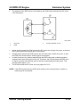
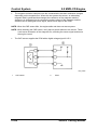
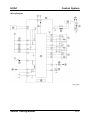
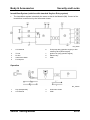
•
Fuel System
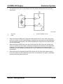
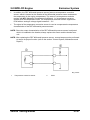
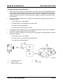
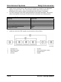
The injectors are directly driven by the PCM. The module has a high-voltage generator
inside, which amplifies the battery voltage into a high voltage of approx. 90 V and stores
it in a capacitor. A control circuit outputs the high voltage to the injectors as a drive
signal.
M5_01073
1
2
3
4
•
From PCM control relay
High voltage generator
PCM
Injector no.1
5
6
7
8
Injector no 2
Injector no 3
Injector no.4
Control circuit
All injectors are connected in parallel, i.e. they feature the same PCM terminal for the
positive voltage supply. In case of an open circuit on one injector the PCM cuts off the
power supply for this injector, so that the engine still runs on three cylinders.
Service Training Mazda5
01-49
Fuel System
2.0 MZR-CD Engine
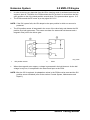
•
When the required injection amount is small, the PCM outputs a short drive signal to the
injectors. As a result, the opening time of the injectors is short, resulting in a small
injection amount.
•
When the required injection amount is large, the PCM outputs a long drive signal to the
injectors. As a result, the opening time of the injectors is long, resulting in a large
injection amount.
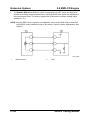
Injector Correction Factors
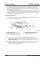
•
The manufacturing tolerances of the injectors are taken into account by injector
correction factors. The correction factors are determined during injector production and
are labeled as hexadecimal numbers (seven four-digit blocks and one two-digit block) on
top of the injector connector.
•
At the end of the vehicle production line the injector correction factors of the installed
injectors are programmed into the PCM. Hereby the PCM equalizes the injection amount
of the individual injectors in order to improve engine running, combustion noise and
exhaust emissions.
M5_01029
1
Injector correction factor
2
View from A
NOTE: After replacing one or more injectors, several steps must be performed to ensure
their proper function (refer to the section “Control System, Maintenance and Repair”).
01-50
Service Training Mazda5
2.0 MZR-CD Engine
Fuel System
NOTE: When re-installing the injectors after a repair, they must be matched to the cylinders
they were removed from. Therefore make a note of the injector correction factors and
the allocated cylinders before removing the injectors. Failure to follow this instruction
may cause irregular idling, increased combustion noise and/or increased black
smoke emissions.
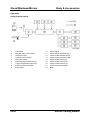
Injection Amount Learning Function
•
The injection amount learning function has been modified. As a result, the PCM carries
out the injection amount learning function every 150 km within the first 1,500 km and
after that every 3,000 km, when all of the following conditions are met:
–
–
–
–
–
–
–
•
Engine is idling
Shift lever is in Neutral position
Vehicle speed is 0 km/h
Engine coolant temperature is between 65…95 °C
A/C is not operating
Accelerator pedal is not depressed
DPF regeneration is not performed
If any of these conditions change while carrying out the injection amount learning
function, the process will be suspended until the conditions are once again met. In
addition, the injection amount learning function has to be carried out at specified service
intervals (refer to the workshop manual).
NOTE: The injection amount learning function is performed several times at a fuel pressure
of 35 MPa, 65 MPa, 100 MPa and 140 MPa. As a result, slight changes in engine
sound are normal.
NOTE: The injection amount learning function will be aborted, if the idle fluctuation of the
engine is too high (e.g. due to a faulty injector). In this case the WDS indicates a
communication fault, although the communication between WDS and PCM is okay
Service Training Mazda5
01-51
Emission System
2.0 MZR-CD Engine
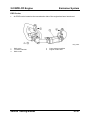
Emission System
Parts Location
M5_01030
1
2
Oxidation catalytic converter and diesel
particulate filter
EGR cooler
01-52
3
Intake shutter valve
4
EGR valve
Service Training Mazda5
2.0 MZR-CD Engine
Emission System
Exhaust System
Features
•
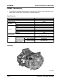
The exhaust system of the vehicles with 2.0 MZR-CD engine has the following features:
–
–
Warm-up oxidation catalytic converter has been cancelled.
Diesel particulate filter integrated in the housing of the oxidation catalytic converter
has been introduced.
Parts Location
M5_01031
1
2
3
Exhaust manifold
Flexible pipe
Oxidation catalytic converter and diesel
particulate filter
Service Training Mazda5
4
5
Middle pipe
Main silencer
01-53
Emission System
2.0 MZR-CD Engine
Exhaust Gas Recirculation System
Features
•
The exhaust gas recirculation system of the vehicles with 2.0 MZR-CD engine has the
following features:
–
–
–
EGR valve with direct current motor and position sensor has been introduced.
EGR cooler located at the transmission-side of the engine has been introduced.
Intake shutter valve with direct current motor and position sensor has been
introduced.
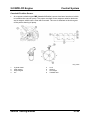
EGR Valve
•
An EGR valve with DC (Direct Current) motor and position sensor has been introduced.
A threaded spindle transforms the rotational movement of the motor into an axial
movement of the EGR valve.
M5_01032
1
2
3
EGR valve position sensor
Valve
Push rod
01-54
4
5
6
Return spring
DC motor
Exhaust gas flow
Service Training Mazda5
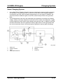
2.0 MZR-CD Engine
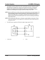
•
Emission System
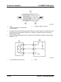
The position of the EGR valve is controlled by the PCM, which activates the DC motor
via a duty signal.
M5_01033
1
2
DC motor
PCM
3
Current detection circuit
•
At low engine speeds the PCM controls the DC motor with a large duty cycle, so that the
EGR valve opens and exhaust gas is recirculated.
•
At high engine speeds the PCM controls the DC motor with a small duty cycle, so that
the EGR valve closes and no exhaust gas is recirculated.
•
In order to remove any carbon deposits from the EGR valve seat a cleaning mode is
activated each time the engine is shut off. Therefore, the PCM actuates the EGR valve
so that it is moved from the fully open to the fully closed position several times. This
process takes approx. 10 s.
•
The PCM controls the DC motor by a duty signal 0 V/12 V.
NOTE: If the EGR system fails, the EGR valve adopts in the closed position in which no
exhaust gas is recirculated.
Service Training Mazda5
01-55
Emission System
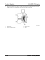
•
2.0 MZR-CD Engine
The EGRVP (EGR Valve Position) sensor is integrated in the DC motor and detects its
position by a sliding contact potentiometer. When the EGR valve opens the resistance of
the potentiometer rises. The sensor supplies the PCM with an analogue voltage signal
between 0…5 V.
NOTE: After the EGR valve is replaced, its adaptation values in the PCM must be reset and
the EGRVP sensor initialized (refer to the section “Control System, Maintenance and
Repair”).
M5_01034
1
EGRVP sensor
01-56
2
PCM
Service Training Mazda5
2.0 MZR-CD Engine
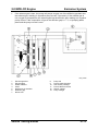
Emission System
EGR Cooler
•
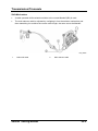
An EGR cooler located at the transmission-side of the engine has been introduced.
M5_01061
1
2
3
EGR valve
To intake manifold
EGR cooler
Service Training Mazda5
4
5
From exhaust manifold
Engine coolant flow
01-57
Emission System
2.0 MZR-CD Engine
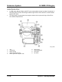
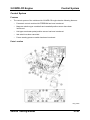
Intake Shutter Valve
•
An ISV (Intake Shutter Valve) with DC motor and position sensor has been introduced. A
reduction gear ensures, that a large rotation angle of the motor results in a small rotation
angle of the valve.
•
The valve body is connected to the engine coolant circuit to prevent icing of the ISV at
low ambient temperatures.
M5_01035
1
2
3
4
5
ISV
Valve body
Return spring
Stator with hall element
Driven gear with magnetic rotor
01-58
6
7
8
9
Drive circuit
Intermediate gear
Drive gear
DC motor
Service Training Mazda5
2.0 MZR-CD Engine
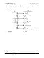
•
Emission System
The position of the ISV is controlled by the PCM, which activates the DC motor via a
duty signal.
M5_01033
1
2
DC motor
PCM
3
Current detection circuit
•
When the required EGR rate is high the PCM controls the DC motor with a large duty
cycle. As a result, the ISV closes halfway, reducing the cross-section of the intake pipe.
Thus a vacuum is generated in the intake manifold and a large amount of exhaust gas
can be recirculated.
•
When the required EGR rate is low the PCM controls the DC motor with a small duty
cycle. As a result, the ISV opens, making the complete cross-section of the intake pipe
available. Thus atmosphere or boost pressure is generated in the intake manifold
(depending on the operating conditions) and only a small amount of exhaust gas can be
recirculated.
•
When the engine is switched off the PCM controls the DC motor with maximum duty
cycle. As a result, the ISV closes fully and no air is induced into the engine, preventing
bucking movements during shut-off.
Service Training Mazda5
01-59
Emission System
2.0 MZR-CD Engine
•
In order to remove any deposits from the ISV a cleaning mode is activated each time the
engine is shut off. Therefore, the PCM actuates the ISV so that it is moved from the fully
open position to the fully closed position several times. This process takes approx. 10 s.
•
The PCM controls the DC motor by a duty signal 0 V/12 V.
NOTE: If the ISV system fails, the ISV adopts in the open position in which no vacuum is
produced.
•
The ISV position sensor is integrated in the cover of the valve body and detects the ISV
position by a hall-type sensor. The sensor consists of a stator with hall element and a
magnetic rotor joint to the driven gear.
M5_01036
1
•
ISV position sensor
2
PCM
When the magnetic rotor rotates, a voltage is generated in the hall element. As the hall
voltage is very low, it is amplified in the sensor and input to the PCM.
NOTE: After the ISV is replaced, its adaptation values in the PCM must be reset and the ISV
position sensor initialized (refer to the section “Control System, Maintenance and
Repair”).
01-60
Service Training Mazda5
2.0 MZR-CD Engine
Emission System
Diesel Particulate Filter System
Features
•
The diesel particulate filter system of the vehicles with 2.0 MZR-CD engine has the
following features:
–
Diesel particulate filter with differential pressure sensor and three exhaust gas
temperature sensors (upper/middle/lower) has been introduced.
–
Heated oxygen sensor located behind the diesel particulate filter has been
introduced.
Diesel Particulates
•
Under engine operating conditions such as cold start, acceleration and high load the
combustion process of the diesel engine is incomplete, resulting in an increased
formation of soot particles. These microscopically small particles have a diameter of only
about 0.05 µm.
•
Soot itself has no harmful effect on the human organism. Hydrocarbons originating from
the fuel and lubricants, as well as water and sulphates, attach themselves to these
granulates, increasing their size to 0.09 µm. In this way the harmful soot particles are
formed.
•
The human nose and bronchial tubes are not able to filter out particles smaller than
2.5 µm (for comparison: a hair is about 70 µm thick). As a result, the particles can then
penetrate through the airways deep into the lungs and pose a health threat especially to
children and adults with certain medical conditions. Soot particles are suspected of
triggering allergies and even cancer. This is especially true of the smallest particles
measuring between 0.1…1.0 µm.
•
The European Union is introducing progressively stricter emissions legislation to achieve
a long-lasting reduction in air pollution from vehicle emissions. As part of this legislation,
all new Diesel passenger vehicles requiring type approval from January 1st 2005 must
comply with the Euro 4 emission standard. In addition, all Diesel passenger vehicles first
registered from January 1st 2006 must meet the Euro 4 standard.
Service Training Mazda5
01-61
Emission System
2.0 MZR-CD Engine
•
In comparison to the particulate matter limit for Euro 3 vehicles (0.05 g/km), the limit for
Euro 4 vehicles (0.025 g/km) has been lowered by 50 %. In order to comply with the
strict Euro 4 emission legislation, the Mazda5 CR with 2.0 MZR-CD engine is equipped
with a diesel particulate filter system.
•
The following sample calculation shows the benefit of a diesel particulate filter: A modern
Common Rail diesel engine without diesel particulate filter has emitted on average about
3 kg of soot after 80.000 km. With a filter it would have emitted less than 100 g over the
same mileage, which is a reduction of 95 %.
Diesel Particulate Filter
•
The oxidation catalytic converter and the DPF (Diesel Particulate Filter) are located one
behind another in a combined housing.
M5_01037
1
2
3
4
Oxidation catalytic converter and DPF
Heated oxygen sensor
Exhaust gas temperature sensor (lower)
Exhaust gas temperature sensor (middle)
5
6
7
Exhaust gas temperature sensor (upper)
Connection for reference pressure
Connection for high pressure
NOTE: To ensure proper function of the DPF system only mineral diesel fuel with a
maximum sulphur proportion of 350 ppm according to DIN EN 590 must be used.
The use of fuel with a higher sulphur proportion is strictly forbidden as this can lead
to blockage of the DPF.
NOTE: Mixing of any additives with metallic compounds to the diesel fuel (e.g. valve cleaner,
coldstart accelerator) is strictly forbidden since this leads to an increased ash
formation, resulting in a blocked DPF.
01-62
Service Training Mazda5
2.0 MZR-CD Engine
•
Emission System
The DPF is a monolith made of silicon carbide ceramics, which features a high
resistance against temperature fluctuations. The individual channels of the filter have
porous dividing walls and are closed at alternative ends. As a result, the exhaust gas is
forced to flow through the dividing walls, which retain the soot particles and allow
gaseous components to pass. The accumulation of particles in the filter increases the
filtration effect still further.
M5_01038
1
2
•
Cleaned exhaust gas
DPF
3
4
Exhaust gas from engine
Oxidation catalytic converter
To avoid the DPF from becoming blocked with soot particles it must be regenerated at
regular intervals, i.e. the soot particles accumulated in the filter are burnt off. In addition,
the regeneration process reduces the exhaust gas back-pressure caused by the soot
amount accumulated, preventing an increase in fuel consumption.
NOTE: On vehicles with a higher mileage soot residues can often form on the exhaust
tailpipe. This is an inherent by-product of the regeneration process and should not be
considered a concern.
NOTE: Under certain conditions it is possible for white smoke to be emitted from the exhaust
tailpipe during regeneration. This is also a by-product of the regeneration process
and should not be considered a concern.
Service Training Mazda5
01-63
Emission System
2.0 MZR-CD Engine
•
The channels of the DPF are coated with platinum. This catalytic coating facilitates the
regeneration of the filter by significantly lowering the light-off temperature of the soot and
by accelerating the combustion of the particles. Without coating the burn-off of the
particles takes place above a temperature of approx. 600 °C. Due to the effect of the
platinum coating the light-off temperature of the soot is lowered to 500 °C.
•
After regeneration ash residues that have formed from the engine oil and diesel fuel
remain in the DPF and cannot be further converted. These residues reduce the usable
filter volume, shortening the regeneration intervals. Since the filter pores are clogged by
the ash residues, the exhaust gas back-pressure and hence the fuel consumption are
increased. Due to the use of an engine oil with low ash content, these effects can be
reduced to a minimum. For this reason, there is no replacement interval given for the
filter.
•
However, depending on the operating conditions the usable filter volume reaches the
limit within the lifetime of the vehicle. In this case, the DPF must be replaced.
NOTE: After replacing the DPF, several steps must be performed to ensure its proper
function (refer to the section “Control System, Maintenance and Repair”).
M5_01039
X
1
2
Exhaust-gas volume flow
Used filter
New filter
01-64
Y
3
Differential pressure
Differential pressure limit
Service Training Mazda5
2.0 MZR-CD Engine
Emission System
DPF Differential Pressure Sensor
•
The DPF differential pressure sensor detects the pressure difference in the exhaust gas
flow upstream and downstream of the DPF. The pressure difference is a measure for the
soot amount accumulated in the filter (i.e. the higher the pressure difference, the higher
the soot amount). The sensor is located in the engine compartment at the bulkhead and
is connected to the upstream and downstream measuring point of the DPF by means of
pressure lines.
•
The differential pressure sensor consists of a pressure chamber with integrated semiconductor element. The electrical resistance of the element varies, when its shape
changes due to exposure to pressure.
M5_01040
1
2
3
DPF differential pressure sensor
Pressure lines
Oxidation catalytic converter and DPF
Service Training Mazda5
4
5
6
Temperature correction sensor
Connection for reference pressure
Connection for high pressure
01-65
Emission System
2.0 MZR-CD Engine
M5_01041
1
2
DPF
Measuring points for DPF differential
pressure sensor
3
Oxidation catalytic converter
•
The signal of the DPF differential pressure sensor is used to determine, whether the soot
amount requires regeneration of the filter. In addition, the signal serves to monitor the
regeneration process.
•
The DPF differential pressure sensor supplies the PCM with an analogue voltage signal
between 0…5 V.
M5_01042
1
DPF differential pressure sensor
01-66
2
PCM
Service Training Mazda5
2.0 MZR-CD Engine
Emission System
•
In addition, the DPF differential pressure sensor features a temperature correction
sensor, which is located on the bracket of the differential pressure sensor and detects
the temperature in the engine compartment. The sensor is a temperature-resistive
resistor with NTC (Negative Temperature Coefficient), i.e. its resistance becomes
smaller when the temperature rises. The temperature correction sensor supplies the
PCM with an analogue voltage signal between 0…5 V.
•
The signal of the temperature correction sensor is used to compensate the temperature
characteristics of the DPF differential pressure sensor.
NOTE: Since the output characteristics of the DPF differential pressure sensor is adjusted
while it is installed to the bracket, always replace the sensor and the bracket as a
unit.
NOTE: After replacing the DPF differential pressure sensor, several steps must be performed
to ensure its proper function (refer to the section “Control System, Maintenance and
Repair”).
M5_01042A
1
Temperature correction sensor
Service Training Mazda5
2
PCM
01-67
Emission System
2.0 MZR-CD Engine
Diagnostics
•
Since the filter itself creates a certain resistance in the exhaust gas flow, the signal of the
DPF differential pressure sensor is also used to determine the filter condition.
M5_01043
X
1
2
3
4
Exhaust-gas volume flow
Blocked condition of filter
Overloaded condition of filter
Loaded condition of filter
Intermediate condition of filter
Y
5
6
7
Differential pressure
Regenerated condition of filter
Damaged condition of filter
Differential pressure limit
•
If the value measured by the DPF differential pressure sensor is above a certain limit,
the DPF is recognized as being blocked. Then the PCM stores a corresponding DTC,
illuminates the MIL and activates the limp home mode.
•
The blocking of the DPF is often as a result of excessive soot emission by the engine
(e.g. due to EGR valve stuck open, leak in the intake-air system etc.) or can be attributed
to multiple failed regeneration processes. To rectify this concern, a manual regeneration
should be carried out using WDS (refer to the section “Control System, Maintenance and
Repair”).
01-68
Service Training Mazda5
2.0 MZR-CD Engine
Emission System
•
If the value measured by the DPF differential pressure sensor is below a certain limit, the
DPF is recognized as being damaged. Then the PCM stores a corresponding DTC,
illuminates the MIL and activates the limp home mode.
•
In this case, the DPF differential pressure sensor should be checked first. Call up the
Datalogger of the PCM and select the PID EXHPRESS_DIF (Press). Then connect a
hand-operated pressure/vacuum pump to the upstream pressure line at the DPF, apply a
pressure of 30 kPa and monitor the PID. If the PID indicates 30 kPa, replace the DPF.
Otherwise check the upstream pressure line and the DPF differential pressure sensor.
Service Training Mazda5
01-69
Emission System
2.0 MZR-CD Engine
Exhaust Gas Temperature Sensors
•
The three exhaust gas temperature sensors (upper/middle/lower) are located in the
combined housing of the oxidation catalytic converter/DPF and detect the temperature of
the exhaust gas upstream of the oxidation catalytic converter, as well as upstream and
downstream of the DPF. Each sensor is a temperature-resistive resistor with NTC, i.e. its
resistance becomes smaller when the temperature rises. Each exhaust gas temperature
sensor supplies the PCM with an analogue voltage signal between 0…5 V.
M5_01044
1
2
3
4
Exhaust gas temperature sensor (upper)
Oxidation catalytic converter and DPF
Exhaust gas temperature sensor (lower)
Exhaust gas temperature sensor (middle)
01-70
5
6
7
8
Exhaust gas temperature sensor
NTC element
Cover
Sheath pin
Service Training Mazda5
2.0 MZR-CD Engine
Emission System
•
The signal of the upper exhaust gas temperature sensor allows to check, whether the
exhaust gas temperature required for operation of the oxidation catalytic converter is
reached.
•
The signal of the middle exhaust gas temperature sensor is used to determine, whether
the exhaust gas temperature required for regeneration of the filter is reached.
•
The signal of the lower exhaust gas temperature sensor serves to monitor the exhaust
gas temperature during the regeneration process.
•
In addition, the information from the exhaust gas temperature sensors is used for the
calculation of the soot amount burnt off in the DPF.
M5_01042A
1
Exhaust gas temperature sensor
Service Training Mazda5
2
PCM
01-71
Emission System
2.0 MZR-CD Engine
Heated Oxygen Sensor
•
The HO2S (Heated O2 Sensor) is located behind the DPF and detects the oxygen
concentration in the exhaust gas. The HO2S is a broad-band type sensor, i.e. it
generates a clear electrical signal in a wide range from λ = 0.7…∞ (∞ = air with 21 %
oxygen). As a result, the sensor is also capable of detecting the oxygen concentration in
the exhaust gas of a diesel engine, which generally works with an excess-air factor of
λ ∼ 1.4 (at full load) to λ ∼ 3.4 (at idle).
•
The information of the HO2S is used for the calculation of the soot amount burnt off in
the DPF.
M5_01045
1
HO2S
•
The broad-band type HO2S consists of an oxygen pump cell and a narrow-band O2
sensor (= Nernst cell). Between the pump cell and Nernst cell is a diffusion gap, into
which exhaust gas enters through the gas access passage. The Nernst cell compares
the oxygen concentration of the exhaust gas in the diffusion gap to the oxygen
concentration of the ambient air in the reference air chamber, and outputs a voltage to
the PCM.
•
The pump cell serves to maintain the composition of gas in the diffusion gap at λ = 1. By
applying a voltage to the pump cell, oxygen can be pumped from the exhaust gas into
the diffusion gap or vice versa. To achieve this, the PCM compares the output voltage of
the Nernst cell with a reference voltage of 450 mV (equivalent to λ = 1) and controls the
voltage applied to the pump cell accordingly.
01-72
Service Training Mazda5
2.0 MZR-CD Engine
•
Emission System
If the exhaust gas is lean, the pump cell pumps oxygen out of the diffusion gap back into
the exhaust gas, resulting in a positive pump current. Conversely, if the exhaust gas is
rich, oxygen is pumped from the exhaust gas into the diffusion gap, leading to a negative
pump current. If the composition of gas in the diffusion gap is λ = 1, no pumping takes
place and the pump current is zero.
M5_01046
1
2
3
4
5
6
7
Exhaust gas flow
Exhaust pipe
Heater element
PCM
Reference air chamber
Diffusion gap
Nernst cell
Service Training Mazda5
8
9
10
11
12
13
Pump cell
Porous protective layer
Gas access passage
Porous diffusion barrier
Sensor voltage
Pump voltage
01-73
Emission System
•
2.0 MZR-CD Engine
The HO2S supplies the PCM with a current between -1.8…+1.8 mA.
M5_01047
X
•
Excess-air factor λ
Y
Current
Since the HO2S only generates a usable signal above a certain temperature, it features
an integral heater element. The temperature of the HO2S is controlled by the PCM,
which activates the heater element via a duty signal.
M5_01048
1
2
From PCM control relay
Heater element
01-74
3
PCM
Service Training Mazda5
2.0 MZR-CD Engine
Emission System
•
At low exhaust gas temperatures the PCM controls the heater element by a large duty
cycle, so that the required operating temperature is reached quickly.
•
At high exhaust gas temperatures the PCM controls the heater element by a small duty
cycle, so that no heating takes place.
•
The PCM controls the heater element by a duty signal 0 V/12 V.
NOTE: After replacing the HO2S, its adaptation values in the PCM must be reset (refer to the
section “Control System, Maintenance and Repair”).
DPF Indicator Light
•
The DPF indicator light is located in the instrument cluster and serves to alert the driver
to a malfunction in the DPF system. During normal operation the DPF indicator light
illuminates when the ignition is on and is extinguished after a few seconds. If the DPF
indicator light illuminates or flashes during driving, then a fault has been detected.
M5_01049
Service Training Mazda5
01-75
Emission System
2.0 MZR-CD Engine
Regeneration Control
•
The regeneration control determines the soot amount accumulated in the DPF and starts
the regeneration process accordingly. The regeneration control is integrated in the PCM.
Soot Amount Calculation
•
The PCM receives information about the soot amount accumulated in the filter from the
DPF differential pressure sensor. In order to establish the soot emission of the engine,
the PCM evaluates the customers driving method by monitoring the engine load, engine
speed and vehicle speed. In addition, the PCM calculates the soot amount burnt off in
the DPF using the signals from the HO2S and the exhaust gas temperature sensors.
•
Depending on the signal from the DPF differential pressure sensor, the calculated soot
emission, the burnt-off soot amount and the distance travelled, the PCM decides
whether and when a regeneration should be carried out. In this way, the filter does
neither become blocked nor damaged by a violent regeneration following an overaccumulation of soot. As a result, it is possible to maintain the long-term integrity of the
DPF while achieving minimum fuel consumption, minimum oil dilution and optimum
engine performance.
•
If the soot accumulation rate in the DPF is 80 % or more, the DPF indicator light
illuminates. In this case an automatic regeneration of the DPF must be penabled by
driving the vehicle at an engine speed of 2000 min-1 or more and a vehicle speed of
40 km/h or more for approx. 10…15 min. As soon as the automatic regeneration process
starts, the DPF indicator light turns off.
NOTE: Although the DPF indicator light turns off when the automatic regeneration is started,
the regeneration process is continued until the soot accumulation rate decreases to
60 % or less.
NOTE: If the customer complains that the DPF indicator light illuminates frequently, he must
be informed to change the driving method (such as driving the vehicle at middle or
high engine speeds for a longer distance), so that regeneration of the DPF is
enabled.
•
If the soot accumulation rate in the DPF reaches 100 % or more, the DPF indicator light
flashes and DTC P2458 is stored in the PCM. In addition, the PCM reduces the fuel
injection amount to lower the exhaust gas temperature, preventing the filter from
overheating. Due to the reduced injection amount the soot emission of the engine and
hence the soot amount accumulated in the filter is also reduced. In this case a manual
regeneration of the DPF must be performed.
01-76
Service Training Mazda5
2.0 MZR-CD Engine
Emission System
NOTE: Do NOT perform automatic regeneration when the soot accumulation rate in the DPF
is 100 % or more, since this may cause damage to the filter or the engine.
•
If the soot accumulation rate in the DPF reaches 140 % or more, the MIL also illuminates
and DTC P242F is stored in the PCM. In addition, the PCM further reduces the fuel
injection amount and hence the soot emission of the engine, resulting in a lower soot
amount accumulated in the filter. Here, a manual regeneration of the DPF must also be
performed.
•
If the soot accumulation rate in the DPF reaches 200 %, the filter cannot be regenerated
anymore and must therefore be replaced.
•
The different conditions of the soot accumulation in the DPF are described in the
following table:
Item
Soot accumulation in the DPF
Soot accumulation
rate
60%
DPF indicator light
—
MIL
80%
—
100%
125%
Illuminates
140%
200%
Flashes every 0.4 s
—
—
—
Output restriction
—
—
—
Max. 150 km/h (93 mph)
Max. 70 km/h (43 mph)
DTC stored in PCM
—
—
—
P2458
P242F
—
Enable automatic
regeneration by
driving the vehicle at
an engine speed of
2,000 rpm or more
and a vehicle speed
of 40 km/h (22 mph)
or more for 10...15
min
Customer action
—
DPF automatic
regeneration
—
Dealer action
—
—
—
Bring the vehicle to a dealer
Enabled
—
Illuminates
Disabled
Perform
manual
regeneration
(normal mode)
Perform manual
regeneration
(long mode)
Replace the
DPF
M5_01T013
Service Training Mazda5
01-77
Emission System
2.0 MZR-CD Engine
Regeneration Process
•
Due to the effect of the catalytic coating the diesel particles are burnt off above a
temperature of 500 °C. Since the exhaust gas temperature during normal driving is
between 150…400 °C (depending on the engine operating conditions), it must be
increased artificially by external intervention from the engine management system to
start the regeneration process.
•
If regeneration of the DPF is required, the PCM checks whether the engine operating
conditions are suitable to start the regeneration process. If the requirements for
regeneration are met, the PCM performs the following measures to artificially increase
the exhaust gas temperature:
–
Closing the EGR valve to increase the combustion temperature by highering the
oxygen proportion of the cylinder charge
–
Closing the ISV partially to increase the combustion temperature by reducing the
excess air
–
Performing an early post-injection to increase the combustion temperature by
burning an additional fuel amount
–
Performing two late post-injections to increase the exhaust gas temperature by
burning fuel in the oxidation catalytic converter
•
By these measures the minimum exhaust gas temperature of 150 °C (at low engine load
and engine speed) is increased to 500 °C and regenerations starts. Then the PCM
monitors the regeneration process using the signals from the DPF differential pressure
sensor and from the exhaust gas temperature sensors. Control over the regeneration
process is critically important since the DPF is damaged when its temperature exceeds
1000 °C.
•
The regeneration process takes up to 15 min. When regeneration has started it will be
completed regardless of the engine operating conditions. It is only stopped when the
engine is shut off. In this case, the regeneration process is started again once the
required operating conditions are met.
01-78
Service Training Mazda5
2.0 MZR-CD Engine
Emission System
Regeneration Intervals
•
Depending on the operating conditions of the vehicle the DPF is regenerated every
100…300 km. Due to the ash residues that have formed from the engine oil and diesel
fuel the usable filter volume is reduced. Since the ash amount accumulated in the DPF
increases with every regeneration process, the regeneration intervals become shorter
with rising mileage.
NOTE: High fuel consumption, low fuel quality (high sulphur content), high engine oil
consumption and low oil quality (high ash content) accelerate the accumulation of
ash in the DPF, shortening the regeneration intervals more quickly.
Service Training Mazda5
01-79
Charging System
2.0 MZR-CD Engine
Charging System
Features
•
The charging system of the vehicles with 2.0 MZR-CD engine has the following features:
–
Smart charging system has been introduced.
Specifications
Battery
Generator
Item
Voltage
Type and capacity
(5-hour rate)
Output
Regulated voltage
Self diagnosis function
(V)
Specification
12
(Ah)
95D31L (64), 115D31L (70)
(V-A)
12-90
Controlled by PCM
M5_01T014
Parts Location
M5_01050
1
Generator
01-80
2
Battery
Service Training Mazda5
2.0 MZR-CD Engine
Charging System
Smart Charging System
•
A so-called "Smart Charging System” has been introduced to improve battery charging
and durability. The exciting current of the field coil and hence the charging voltage is
controlled by the PCM, which actuates the generator by a duty signal. In addition, the
generator sends a feedback signal to the PCM, which hereby monitors the generator
load.
•
The PCM determines the duty ratio outputted to the generator according to the battery
voltage, battery electrolyte temperature (derived from the intake air temperature, engine
coolant temperature and vehicle speed signal) and generator load. In addition, the PCM
transmits information about the generator warning light status via the high-speed CAN
bus to the instrument cluster, which activates the generator warning light accordingly.
M5_01051
1
2
3
4
Stator coil
Power transistor
PCM
High-speed CAN bus
Service Training Mazda5
5
6
7
Instrument cluster
Battery
Field coil
01-81
Charging System
2.0 MZR-CD Engine
•
When the battery voltage/battery electrolyte temperature is high and/or the generator
load is low, the PCM controls the generator with a small duty cycle. As a result, a low
exciting current flows through the field coil and the generator outputs a low charging
voltage.
•
When the battery voltage/battery electrolyte temperature is low and/or the generator load
is high, the PCM controls the generator with a large duty cycle. As a result, a high
exciting current flows through the field coil and the generator outputs a high charging
voltage.
01-82
Service Training Mazda5
2.0 MZR-CD Engine
Control System
Control System
Features
•
The control system of the vehicles with 2.0 MZR-CD engine has the following features:
–
–
Powertrain control module with FEEPROM has been introduced.
–
–
–
Hall-type accelerator pedal position sensor has been introduced.
Magneto resistive-type crankshaft and camshaft position sensor have been
introduced.
Idle switch has been cancelled.
Power steering pressure switch has been introduced.
Parts Location
M5_01052
Service Training Mazda5
01-83
Control System
A
1
2
3
4
5
6
7
8
9
10
11
12
13
14
15
16
LHD
Exhaust gas temperature sensor
Park neutral position switch
Intake air temperature sensor no.2
Crankshaft position sensor
MAF/IAT sensor
ISV with DC motor and position sensor
EGR valve with DC motor and position
sensor
Engine coolant temperature sensor
Fuel temperature sensor
Fuel metering valve
Generator (stator coil and field coil)
Fuel pressure sensor
Glow plug
MAP sensor
Fuel injector
Refrigerant pressure switch
01-84
2.0 MZR-CD Engine
B
17
18
19
20
21
22
23
RHD
Main fuse box
Glow plug relay
Starter relay
PCM control relay
A/C relay
DPF differential pressure sensor
Temperature correction sensor
24
25
26
27
28
29
30
31
32
Power steering pressure switch
Camshaft position sensor
VBC solenoid valve
Accelerator pedal position sensor
Brake switch
Clutch pedal position switch
PCM (with built-in BARO sensor)
Cruise control switches
HO2S
Service Training Mazda5
2.0 MZR-CD Engine
Control System
Relationship Chart
Output
Input
Refrigerant pressure switch
Cruise control switches
Accelerator pedal position sensor
MAF/IAT sensor
IAT sensor no.2
Engine coolant temperature sensor
Fuel temperature sensor
BARO sensor (integrated in PCM)
MAP sensor
Fuel pressure sensor
Camshaft position sensor
Crankshaft position sensor
Vehicle speed signal
Generator (stator coil)
DPF differential pressure sensor
Temperature correction sensor
Exhaust gas temperature sensor
(upper/middle/lower)
ISV position sensor
EGRVP sensor
HO2S (sensor)
Immobilizer-related information
Starter relay
Fuel metering valve
Fuel injectors
VBC solenoid valve
EGR valve DC motor
ISV DC motor
Glow indicator light
Cruise main indicator light
Cruise set indicator light
Glow plug relay
Generator (field coil)
HO2S (heater element)
A/C relay
Fan control module
Immobilizer-related information
X
X
X
X
X
X
Immobilizer system
Generator control
A/C control
X
X
X
X
X
Electrical fan control
X
X
Cruise control system
X
X
DPF regeneration control
HO2S heater control
X
X
X
EGR control
X
X
X
ISV control
X
X
X
Fuel pressure control
Multiple injection control
X
X
Injection timing control
X
Injection amount control
X
X
X
Variable boost control
Battery
Starter signal
Clutch pedal position switch
Park/Neutral position switch
Brake switch
Power steering pressure switch
Glow control
Device
Idle speed control
Control Item
X
X
X
X
X
X
X
X
X
X
X
X
X
X
X
X
X
X
X
X
X
X
X
X
X
X
X
X
X
X
X
X
X
X
X
X
X
X
X
X
X
X
X
X
X
X
X
X
X
X
X
X
X
X
X
X
X
X
X
X
X
X
X
X
X
X
X
X
X
X
X
X
X
X
X
X
X
X
X
X
X
X
X
X
X
X
X
X
X
X
X
X
X
X
X
X
X
X
X
X
X
X
X
X
X
X
X
X
X
X
X
X
X
X
X
X
X
X
X
X
X
X
X
X
X
X
X
X
X
M5_01T015
Service Training Mazda5
01-85
Control System
2.0 MZR-CD Engine
Powertrain Control Module
•
The PCM (Powertrain Control Module) is located behind a cover in the passenger
footwell and features a 121-pin (two-block) connector.
NOTE: When replacing the PCM, several steps must be performed to ensure its proper
function (refer to the section “Control System, Maintenance and Repair”).
M5_01062
1
Wiring harness side-connector of the PCM
•
The PCM features an FEEPROM (Flash Electronically Erasable Programmable ROM),
which can be erased electronically by a flash voltage and reprogrammed with updated
calibration data. As a result, the strategy program and the calibration data logged in the
FEEPROM can be updated without replacing the PCM.
•
If the PCM should be updated with a later software calibration, the module has to be
reprogrammed with the aid of the WDS. Therefore, select the option ToolboxÆ
Module ProgrammingÆModule ReprogrammingÆPCM and follow the instructions of
the WDS.
NOTE: As later software calibrations are usually released to resolve specific customer
concerns, module reprogramming should only be carried out when recommended
e.g. by a Service Information or by the Technical Hotline/Technical Service
Department.
01-86
Service Training Mazda5
2.0 MZR-CD Engine
Control System
Crankshaft Position Sensor
•
An magneto resistive-type CKP (Crankshaft Position) sensor has been introduced,
which is located at the rear side of the clutch housing. The sensor consists of two
magneto resistive elements and a magnet, which scan a rotor with 56 teeth, missing five
teeth in one location. The rotor is integrated in the flywheel.
M5_01053
1
2
3
4
Clutch housing
CKP sensor
Output signal
5V
Service Training Mazda5
5
6
7
8
0.5 V
Ground
Crank angle
Toothed rotor
01-87
Control System
•
2.0 MZR-CD Engine
The magneto resistive elements have the characteristics that their resistance changes
depending on the magnetic flux. When the rotor passes the sensor, an alternating
magnetic field is generated that changes the resistance of the magneto resistive
elements. An integrated circuit converts the output voltage of the magneto resistive
elements into a rectangular wave signal, which is then input to the PCM.
NOTE: When the CKP sensor fails, the engine stalls and does not start anymore.
NOTE: When installing the CKP sensor, verify that no swarfs adhere to the sensor. These
could cause fluctuation of the magnetic flux, affecting the sensor signal and hence
the engine control.
•
The CKP sensor supplies the PCM with a digital voltage signal 0 V/5 V.
M5_01054
1
CKP sensor
01-88
2
PCM
Service Training Mazda5
2.0 MZR-CD Engine
Control System
Camshaft Position Sensor
•
An magneto resistive-type CMP (Camshaft Position) sensor has been introduced, which
is located at the vacuum pump. The sensor consists of two magneto resistive elements
and a magnet, which scan a rotor with five teeth. The rotor is attached to the drive gear
of the power steering oil pump.
M5_01055
1
2
3
4
Cylinder head
CMP sensor
Output signal
5V
Service Training Mazda5
5
6
7
8
0.5 V
Ground
Cam angle
Toothed rotor
01-89
Control System
•
2.0 MZR-CD Engine
The magneto resistive elements have the characteristics that their resistance changes
depending on the magnetic flux. When the rotor passes the sensor, an alternating
magnetic field is generated that changes the resistance of the magneto resistive
elements. An integrated circuit converts the output voltage of the magneto resistive
elements into a rectangular wave signal, which is then input to the PCM.
NOTE: When the CMP sensor is faulty, this can be recognized by the increased engine noise
(Diesel knocking). In order to identify cylinder no.1 during engine start the PCM
injects metered quantities of fuel into the individual cylinders and monitors the engine
speed via the CKP sensor. The cylinder in question is the one where the engine
speed increases after fuel has been injected. As a result, the starting process takes
longer than normal.
NOTE: When installing the CMP sensor, verify that no swarfs adhere to the sensor. These
could cause fluctuation of the magnetic flux, affecting the sensor signal and hence
the engine control.
•
The CMP sensor supplies the PCM with a digital voltage signal 0 V/5 V.
M5_01063
1
CMP sensor
01-90
2
PCM
Service Training Mazda5
2.0 MZR-CD Engine
Control System
Accelerator Pedal Position Sensor
•
A hall-type APP (Accelerator Pedal Position) sensor has been introduced. For safety
reasons the APP sensor consists of two hall elements integrated in the stator and a
magnetic rotor joint to the accelerator pedal.
NOTE: If one hall-type sensor fails, the PCM uses the signal from the other sensor to detect
the driver’s acceleration demand. As a result, the engine speed is limited to approx.
2500 min-1. If the APP sensor fails completely, the engine speed is limited to
1500 min-1.
M5_01056
1
Accelerator pedal
Service Training Mazda5
2
APP sensor
01-91
Control System
•
2.0 MZR-CD Engine
When the magnetic rotor rotates, a voltage is generated in the hall elements. As the hall
voltage is very low, it is amplified in the sensor and input to the PCM.
M5_01057
1
2
Sensor body
Stator with hall elements
01-92
3
4
Magnetic rotor
Shaft
Service Training Mazda5
2.0 MZR-CD Engine
•
Control System
Each hall-type sensor supplies the PCM with an analogue voltage signal between
0…5 V. In order to facilitate failure detection there is a voltage offset of 0.5 V between
both signals.
M5_01064
1
APP sensor
Service Training Mazda5
2
PCM
01-93
Control System
2.0 MZR-CD Engine
Power Steering Pressure Switch
•
A PSP (Power Steering Pressure) switch located at the power steering oil pump has
been introduced to detect the load condition of the power steering. If the power steering
oil pressure exceeds a given value, the switch closes and supplies the PCM with a
voltage signal of 0 V.
M5_01065
1
PSP switch
2
Power steering oil pump
M5_01066
1
PSP switch
01-94
2
PCM
Service Training Mazda5
2.0 MZR-CD Engine
Control System
Maintenance and Repair
Replacing the engine oil
•
Every time the engine oil is replaced, the parameter “Calculated oil dilution” in the PCM
must be reset with the aid of WDS. Therefore, select the option ToolboxÆ
PowertrainÆData ResetÆEngine Oil.
Manual regeneration
•
If the DPF is blocked due to an excessive soot amount accumulated, it must be
regenerated manually with the aid of WDS. Therefore, select the option ToolboxÆ
PowertrainÆDPFÆDPF Regeneration.
•
Depending on the amount of soot accumulated in the DPF the PCM automatically
selects normal regeneration mode (34 min) or long regeneration mode (60 min). Long
regeneration mode is performed when the soot accumulation rate exceeds 125 %. Due
to the longer duration the manual regeneration can be performed at a lower exhaust gas
temperature. As a result, damage of the DPF by a violent regeneration following an overaccumulation of soot is prevented.
•
In order to cancel the manual regeneration process perform the following procedure:
1. Depress the clutch pedal, shift to 1st gear and verify that the engine speed
decreases to idle speed (manual regeneration is cancelled).
2. Shift to neutral and increase the engine speed to 3000 min-1 for 1 min (DPF is
cooled).
3. If the manual regeneration must be performed again, wait for approx. 5 min before
re-starting the regeneration process.
NOTE: Always perform the manual regeneration in a well-ventilated place and use an
appropriate exhaust-gas extraction system. The vehicle should also not be parked in
front of any flammable or low heat resistant material, since high temperature exhaust
gas is emitted during this process. In addition, the hood should be opened to prevent
the engine from overheating. Do NOT apply electrical load (such as turning on the
headlights or rear window defroster) during manual regeneration, since the post
injection amount is changed and regeneration may not be performed correctly.
Service Training Mazda5
01-95
Control System
2.0 MZR-CD Engine
NOTE: If the exhaust gas temperature during manual regeneration exceeds a certain limit,
the PCM stops the regeneration process and increases the engine speed to
2500 min-1 to cool the DPF.
NOTE: Depending on the amount of soot accumulated the PCM performs normal and long
regeneration mode one after another, i.e. the regeneration process may take up to
94 min. If the DPF indicator light does not extinguish after the manual regeneration is
completed, perform the regeneration process again.
Replacing the MAF sensor
•
After replacing the MAF sensor, its adaptation values in the PCM must be reset with the
aid of the WDS. Therefore, select the option ToolboxÆPowertrainÆData ResetÆ
MAF Sensor.
Replacing the high-pressure pump
•
After replacing the high-pressure pump, its adaptation values in the PCM must be reset
with the aid of the WDS. Therefore, select the option ToolboxÆPowertrainÆ
Data ResetÆFuel Pump.
Replacing injectors
•
After replacing one or more injectors, the following steps must be performed:
1. The injector adaptation values in the PCM must be reset using the option ToolboxÆ
PowertrainÆData ResetÆInjector.
2. The injector correction factors must be programmed into the PCM via the option
ToolboxÆModule ProgrammingÆProgrammable ParametersÆInjector
Correction Factors.
3. The injection amount learning function must be performed using the option
ToolboxÆPowertrainÆEngine ChecksÆLearningÆCorrection after Parts
Installation.
01-96
Service Training Mazda5
2.0 MZR-CD Engine
Control System
Replacing the EGR valve or the ISV
•
After replacing the EGR valve or the ISV, its adaptation values in the PCM must be reset
with the aid of the WDS. Therefore, select the option ToolboxÆPowertrainÆ
Data ResetÆETB/EGR. Then the EGRVP sensor or the ISV position sensor must be
initialized using the option ToolboxÆPowertrainÆETB/EGR Initialization.
Replacing the DPF
•
After replacing the DPF, the following steps must be performed:
1. The DPF adaptation values in the PCM must be reset using the option ToolboxÆ
PowertrainÆData ResetÆDPF.
2. The regeneration control in the PCM must be reset via the option ToolboxÆ
PowertrainÆDPFÆDPF Reset.
3. The injection amount learning function must be performed using the option
ToolboxÆPowertrainÆEngine ChecksÆLearningÆInjection Amount
Correction.
4. The DPF must be regenerated manually via the option ToolboxÆPowertrainÆ
DPFÆDPF Regeneration.
5. The pressure difference of the DPF must be assessed using the option ToolboxÆ
PowertrainÆDPFÆDPF Assessment.
Replacing the DPF differential pressure sensor
•
After replacing the DPF differential pressure sensor, the following steps must be
performed:
1. The adaptation values of the DPF differential pressure sensor in the PCM must be
reset using the option ToolboxÆPowertrainÆData ResetÆDPF Pressure
Sensor.
2. The regeneration control in the PCM must be reset via the option ToolboxÆ
PowertrainÆDPFÆDPF Reset.
3. The pressure difference of the DPF must be assessed using the option ToolboxÆ
PowertrainÆDPFÆDPF Assessment.
Service Training Mazda5
01-97
Control System
2.0 MZR-CD Engine
Replacing the HO2S
•
After replacing the HO2S, its adaptation values in the PCM must be reset with the aid of
the WDS. Therefore, select the option ToolboxÆPowertrainÆData ResetÆ
O2 Sensor.
Replacing the PCM
•
After replacing the PCM, the following steps must be performed:
1. The PCM must be configured using the option ToolboxÆModule ProgrammingÆ
Programmable Module InstallationÆPCM.
2. The keys must be programmed via the option ToolboxÆBodyÆSecurityÆPATS
Functions.
3. All the adaptation values in the PCM must be reset using the option ToolboxÆ
PowertrainÆData ResetÆPCM.
4. The EGRVP sensor and the ISV position sensor must be initialized via the option
ToolboxÆPowertrainÆETB/EGR Initialization.
5. The regeneration control in the PCM must be reset using the option ToolboxÆ
PowertrainÆDPFÆDPF Reset.
6. The injection amount learning function must be performed via the options ToolboxÆ
PowertrainÆEngine ChecksÆLearningÆCorrection after Parts
Installation/Injection Amount Correction.
7. The DPF must be regenerated manually via the option ToolboxÆPowertrainÆ
DPFÆDPF Regeneration.
8. The pressure difference of the DPF must be assessed using the option ToolboxÆ
PowertrainÆDPFÆDPF Assessment.
9. Since the parameter “Calculated oil dilution” has also been reset, the engine oil level
must be checked. If the oil level is close to or exceeds the “X” mark on the dipstick,
replace the engine oil.
01-98
Service Training Mazda5
2.0 MZR-CD Engine
On-board Diagnostic System
On-board Diagnostic System
Features
•
The On-board diagnostic system consists of the following functions:
–
–
–
Self-test function
PID monitor function
Simulation test function
Self Test
•
The self-test function allows to read out the CMDTCs of the PCM with the aid of WDS.
Therefore, select the option ToolboxÆSelf TestÆModulesÆPCMÆRetrieve CMDTCs.
•
In addition, the KOEO self-test can be performed using the option ToolboxÆSelf TestÆ
ModulesÆPCMÆKOEO On-demand Self Test.
•
In order to conduct the KOER self-test select the option ToolboxÆSelf TestÆ
ModulesÆPCMÆKOER On-demand Self Test.
Service Training Mazda5
01-99
On-board Diagnostic System
2.0 MZR-CD Engine
PID Monitor
•
The PID monitor function allows to monitor the PIDs of the PCM with the aid of WDS.
Therefore, select the option ToolboxÆDataloggerÆModulesÆPCM.
Item
AC_REQ
ACCS
ALTF
ALTT V
APP
APP_LRN
Definition
A/C ON request
A/C compressor cycling switch
Generator field current control duty cycle
Generator output voltage
Accelerator pedal position
APP learning value - closed
APP1
APP sensor no.1
APP2
APP sensor no.2
ARPMDES
Target idle speed
BARO
Barometric pressure sensor
BOO
BOOST_DSD
CATT11_DSD
CATT12_DSD
CATT21_DSD
CHRGLP
CPP
DEC_CMP
Brake switch
Boost pressure desired
Catalyst temperature desired (upper)
Catalyst temperature desired (middle)
Catalyst temperature desired (lower)
Generator warning light
CPP switch
Fuel correction for deceleration
DSC_ACT
DSC control
DTCCNT
DTC count
ECT
ECT sensor
EGR_LRN
EGR valve learning value - closed
EGRP
EGRVP sensor
EQ_RAT11
ETC_ACT
Equivalence ratio (lambda)
ISV position actual
ETC_DSD
ISV position desired
EXHPRESS_DIF
EXHPRESS_LRN
EXHPRESS2
EXHTEMP1
EXHTEMP2
EXHTEMP3
DPF differential pressure sensor
DPF differential pressure sensor learning value
DPF differential pressure sensor (middle)
Exhaust gas temperature sensor (upper)
Exhaust gas temperature sensor (middle)
Exhaust gas temperature sensor (lower)
Unit/Condition
On/Off
On/Off
%
V
%
V
%
V
%
V
RPM
Pa
V
On/Off
Pa
°C
°C
°C
On/Off
On/Off
No unit
Enabled/
Disabled
No unit
°C
V
mm
V
mm
%
No unit
°
%
°C
Pa
Pa
Pa
°C
°C
°C
M5_01016
01-100
Service Training Mazda5
2.0 MZR-CD Engine
On-board Diagnostic System
Item
FAN_DUTY
FI_LRN_01
FI_LRN_02
FI_LRN_03
FI_LRN_04
FI_LRN_11
FI_LRN_12
FI_LRN_13
FI_LRN_14
FI_LRN_21
FI_LRN_22
FI_LRN_23
FI_LRN_24
FI_LRN_31
FI_LRN_32
FI_LRN_33
FI_LRN_34
FIA_DSD
FIP_FL
FIP_FL_DSD
FIP_SCV
FLT
FP
Definition
Fan control duty cycle
Fuel injection learning value (injector 1 at 35 MPa)
Fuel injection learning value (injector 2 at 35 MPa)
Fuel injection learning value (injector 3 at 35 MPa)
Fuel injection learning value (injector 4 at 35 MPa)
Fuel injection learning value (injector 1 at 65 MPa)
Fuel injection learning value (injector 2 at 65 MPa)
Fuel injection learning value (injector 3 at 65 MPa)
Fuel injection learning value (injector 4 at 65 MPa)
Fuel injection learning value (injector 1 at 100 MPa)
Fuel injection learning value (injector 2 at 100 MPa)
Fuel injection learning value (injector 3 at 100 MPa)
Fuel injection learning value (injector 4 at 100 MPa)
Fuel injection learning value (injector 1 at 140 MPa)
Fuel injection learning value (injector 2 at 140 MPa)
Fuel injection learning value (injector 3 at 140 MPa)
Fuel injection learning value (injector 4 at 140 MPa)
Fuel injection amount desired [mm3/stroke]
High-pressure pump flow
High-pressure pump flow desired
Fuel metering valve
Fuel temperature sensor
Fuel metering valve duty cycle
FRP
Fuel pressure sensor
FRP_A
GENVDSD
GLWPG V
GP_LMP
GPC
Fuel pressure after fuel injection
Generator voltage desired
Glow plug voltage
Glow plug indicator light
Glow plug relay
HTR11
HO2S (heater element)
HTR_OFF
HTR_ON
HO2S voltage - off
HO2S voltage - on
IAT
IAT sensor
IAT2
IAT sensor no.2
ICP
ICP_DSD
INGEAR
ISV_LRN_C
ISV_LRN_O
IVS
LOAD
Injector control pressure
Injector control pressure desired
Load/No load condition
ISV learning value - closed
ISV learning value - open
Idle validation switch
Engine load
Unit/Condition
%
ms
ms
ms
ms
ms
ms
ms
ms
ms
ms
ms
ms
ms
ms
ms
ms
No unit
A
No unit
A
°C
%
V
Pa
Pa
V
V
On/Off
On/Off
%
Ohms
V
V
V
°C
V
°C
Pa
Pa
On/Off
%
%
Idle/Off Idle
%
M5_01T016A
Service Training Mazda5
01-101
On-board Diagnostic System
Item
2.0 MZR-CD Engine
Definition
MAF
MAF sensor
MAF_C
MAF_C_DSD
Mass air flow per cylinder
Mass air flow per cylinder desired
MAP
MAP sensor
MIL
MIL_DIS
O2
O2S11
O2S11_CAL
PM_ACC
PM_ACC_DSD
PM_GEN
PSP
REG_AUTO
REG_MAN
RPM
SC_CANCEL
SC_COAST
SC_MAIN
Malfunction indicator light
Travelled distance since MIL illuminated
Oxygen concentration in exhaust gas
HO2S (sensor)
HO2S calibration value
Soot accumulation amount
Soot accumulation amount desired
Soot generation amount
PSP switch
Automatic regeneration
Manual regeneration
Engine speed
Cruise control cancel switch
Cruise control coast switch
Cruise control main switch
Unit/Condition
g/s
V
g
g
Pa
V
On/Off
km
%
Current
No unit
g/L
g/L
g/L
Low/High
On/Off
On/Off
RPM
Active/Inactive
Active/Inactive
Active/Inactive
Off/Standby/
Active/Tap-up/
Set/Tap-down/
Coast
SC_MODE
Cruise control operation mode
SC_ON
SC_RES
SC_SET
SC_SET/ACC
SCCS
TC_CMP
TIRESIZE
Cruise control actuator switch on
Cruise control resume switch
Cruise control set indicator light
Cruise control set/acceleration switch
Cruise control command switch
Fuel correction for torque-down control [mm3/stroke]
Tire revolution per mile
TP1
ISV position sensor
VBCV
VPWR
VSS
VBC solenoid valve duty cycle
Battery positive voltage
Vehicle speed
On/Off
Active/Inactive
On/Off
Active/Inactive
V
No unit
rev/mile
%
V
%
V
km/h
M5_01T016B
01-102
Service Training Mazda5
2.0 MZR-CD Engine
On-board Diagnostic System
Simulation Test
•
The simulation test function allows to activate certain PIDs of the PCM with the aid of
WDS. Therefore, select the option ToolboxÆDataloggerÆModulesÆPCM.
Item
ACCS
EGRP
GENVDSD
GP_LMP
GPC
INJ_1
INJ_2
INJ_3
INJ_4
VBCV
Definition
A/C compressor cycling switch
EGR valve position sensor
Generator voltage desired
Glow plug indicator light
Glow plug relay
Fuel injector no.1
Fuel injector no.2
Fuel injector no.3
Fuel injector no.4
VBC solenoid valve duty cycle
Service Training Mazda5
x: Applicable
—: Not applicable
Test condition
Unit/Condition
KOEO
KOER
On/Off
X
X
%
X
X
___
V
X
On/Off
X
X
On/Off
X
X
___
On/Off
X
___
On/Off
X
___
On/Off
X
___
On/Off
X
%
X
X
M5_01T0017
01-103
On-board Diagnostic System
2.0 MZR-CD Engine
Notes:
01-104
Service Training Mazda5
02
Suspension
02 Suspension
Wheels and Tires.................................................................................................1
Specifications..................................................................................................1
Standard Tire ............................................................................................1
Temporary Spare Tire...............................................................................1
Front Suspension................................................................................................2
Features..........................................................................................................2
Overview .........................................................................................................2
Specifications..................................................................................................3
Front Shock Absorber .....................................................................................4
Rear Suspension .................................................................................................5
Features..........................................................................................................5
Overview .........................................................................................................5
Specifications..................................................................................................6
Rear Shock Absorber......................................................................................6
Table of Contents 02
Service Training Mazda5
Suspension
Wheels and Tires
Wheels and Tires
•
Wheel and tire sizes are the same as the current Mazda3 (BK), but tire speed ratings
have changed.
Specifications
Standard Tire
Item
Tire
Specifications
Size
195/65R15 91V
205/55R 16 91V
205/50R 17 93V
Size
15 X 6J
16 X 6 1/2J
17 X 6 1/2J
Material
Steel
Wheel
Aluminium
alloy
Aluminium alloy
Offset
(mm {in})
52.5 (2.07)
Pitch circle
diameter
(mm {in})
114.3 (4.50)
M5_02T002
Temporary Spare Tire
Item
Tire
Specifications
Size
T115/70D 15
T125/70D 16
Size
15 X 4T
16 X 4T
Material
Wheel
Steel
Offset
mm/(in)
4.5 (1.8)
Pitch circle
diameter
mm/(in)
114.3 (4.50)
M5_02T003
Service Training Mazda5
02-1
Front Suspension
Suspension
Front Suspension
Features
•
The front suspension of the Mazda5 is essentially the same as the current Mazda3 (BK).
It has the following features:
–
–
–
Strut-type design.
Front crossmember rubber mounted to the body at four points.
Oil filled bushes used for the front lower arms.
Overview
M5_02003
1
2
3
02-2
Front shock absorber and coil spring
Front stabilizer control link
Front stabilizer
4
5
Front lower arm
Front crossmember
Service Training Mazda5
Suspension
Front Suspension
Specifications
Item
Engine type
Type
Spring type
Shock absorber type
Stabilizer
Front
suspension
Wheel
alignment
(unloaded)
Specification
L8,LF
MZR-CD
Strut type
Coil spring
Low-pressure gas charged,
cylindrical, double-acting
Type
Diameter
(mm {in})
Tire
[Tolerance ±4
(mm {in})
Total
{0.15}]
toe-in
Rim inner
Degree
Maximum steering
Inner
angle
Outer
[Tolerance ±3 °]
Torsion bar
23 {0.90}
2 {0.08}
1 ± 3 {0.04 ± 0.12}
0 ° 11´ ± 22
40 ° 05´
33 ° 07´
Caster angle (Reference)
[Tolerance ±1 °]
3 ° 14´
3 ° 12´
Camber angle (Reference)
[Tolerance ±1 °]
-0 ° 42´
-0 ° 44´
Steering axis inclination
(Reference)
13 ° 59´
14 ° 04´
M5_02T001
NOTE: The camber and caster angle are not adjustable.
Service Training Mazda5
02-3
Front Suspension
Suspension
Front Shock Absorber
•
A shock absorber with an internal rebound spring is used to control wheel-lift* during
hard cornering. The rebound spring allows a limited amount of movement of the shock
absorber when it is fully extended. Without the spring the shock absorber would top-out,
making the suspension ineffective and causing wheel hop or wheel lift.
*Wheel-lift: Tendency for wheels on the inside of a curve to lift off the ground during cornering.
M5_02001
1
2
02-4
Rebound spring
Oil chamber
3
Gas chamber
Service Training Mazda5
Suspension
Rear Suspension
Rear Suspension
Features
•
The rear suspension is essentially the same as the current Mazda3 (BK). It has the
following features:
–
–
E-type design layout.
Separate shock absorber and springs.
Overview
M5_02004
1
2
3
4
5
Rear shock absorber
Rear crossmember
Rear trailing link
View from rear of vehicle
Rear lower arm
Service Training Mazda5
6
7
8
9
10
Rear coil spring
Rear stabilizer control link
Rear stabilizer
Rear lateral link
Rear upper arm
02-5
Rear Suspension
Suspension
Specifications
Item
Type
Spring type
Shock absorber type
Stabilizer
Rear
suspension
Wheel
alignment
(unloaded)
Type
Diameter
Tire
[Tolerance ±4
Total
{0.15}]
toe-in
Rim inner
(mm {in})
(mm {in})
Degree
Camber angle [Tolerance ± 1° ]
Specification
Multi-link
Coil spring
High-pressure gas charged,
cylindrical, double-acting
Torsion bar
20 {0.79}
2 {0.08}
1 ± 3 {0.04 ± 0.12}
0 ° 11´ ± 22´
-1°29´
Thrust angle [Tolerance ± 48´]
0°
M5_02T004
NOTE: The camber angle is not adjustable.
Rear Shock Absorber
•
A monotube-type rear shock absorber is used. The advantages of monotube
construction are that oil foaming is eliminated, and that shock absorber performance
does not deteriorate at high temperatures.
M5_02002
1
2
02-6
Oil
Free piston
3
High-pressure gas
Service Training Mazda5
03
Driveline/
Axle
03 Driveline/Axle
Front Axle.............................................................................................................1
Features..........................................................................................................1
Overview .........................................................................................................1
Rear Axle..............................................................................................................2
Features..........................................................................................................2
Overview .........................................................................................................2
Drive Shaft ...........................................................................................................3
Features..........................................................................................................3
Specifications..................................................................................................3
Overview .........................................................................................................3
Table of Contents 03
Service Training Mazda5
Driveline/Axle
Front Axle
Front Axle
Features
•
The front axle on the Mazda5 is essentially the same design as that of the current
Mazda3 (BK). It has the following features:
–
Unit-design angular ball bearings are used.
Overview
M5_03002
1
Wheel hub
Service Training Mazda5
2
Wheel bearing
03-1
Rear Axle
Driveline/Axle
Rear Axle
Features
•
The rear axle on the Mazda5 is essentially the same design as that of the current
Mazda3 (BK). It has the following features:
–
Unit-design angular ball bearings are used.
Overview
M5_03001
1
03-2
Wheel hub (integrated with wheel bearing)
Service Training Mazda5
Driveline/Axle
Drive Shaft
Drive Shaft
Features
•
The drive shafts on the Mazda5 are essentially the same design as those on the current
Mazda3 (BK). They have the following features:
–
–
A bell joint is used for the wheel-side constant velocity joints.
A tripod joint is used for the transaxle-side constant velocity joint.
Specifications
Item
Specifications
LF
Bell joint
Double offset joint
Tripod joint
26.0 {1.02}
L8
Wheel side
Joint type
RH
LH
(mm{in})
Differential side
Shaft diameter
Joint shaft
Shaft diameter
Tripod joint
MZR-CD
Tripod joint
40.0 {1.57}
(mm{in})
M5_03T001
Overview
M5_03003
1
2
Front drive shaft
Joint shaft
Service Training Mazda5
3
4
L8, LF
MZR-CD
03-3
Driveline/Axle
NOTES:
03-4
Service Training Mazda5
04
Brakes
04 Brakes
Conventional Brake System ...............................................................................1
Features..........................................................................................................1
Specifications..................................................................................................1
Master Cylinder...............................................................................................2
Antilock Brake System .......................................................................................3
Features..........................................................................................................3
Parts Location .................................................................................................3
Dynamic Stability Control...................................................................................4
Parts Location .................................................................................................4
Combine Sensor .............................................................................................5
Table of Contents 04
Service Training Mazda5
Brakes
Conventional Brake System
Conventional Brake System
Features
•
The construction and operation of the brake system is essentially the same as the
current Mazda3 (BK). It has the following features:
–
–
–
An intrusion minimizing brake pedal is used.
Mechanical brake assist is included in the power brake unit.
A remote master cylinder reservoir tank has been added.
Specifications
Item
Type
Brake pedal
Pedal lever ratio
Max. Stroke
(mm {in})
Type
Master cylinder
Cylinder bore
(mm {in})
Type
Cylinder bore
(mm {in})
Pad dimensions (area x thickness)
2
2
Front brake
(mm x mm {in x in})
Disc plate dimensions
Rear brake
Rear brake
Power brake
unit
Rear wheel
braking force
control device
Brake piping
Parking brake
Brake fluid
(mm {in})
Type
Cylinder bore
(mm {in})
Pad dimensions (area x thickness)
2
2
(mm x mm {in x in})
Disc plate dimensions
(mm {in})
Type
Outer diameter
(mm {in})
Type
Piping layout
Type
Operating method (application/release)
Play adjustment method
Type
Specification
Suspended design
2.8
117 {4.61}
Tandem
22.2 {0.874}
Ventilated disc
57 {2.2}
5,140 × 12.0 {7.967 × 0.47}
With 15 inch brake: 278 × 25 {10.9 × 0.98}
With 16 inch brake: 300 × 25 {11.8 × 0.98}
Solid disc
38 {1.5}
2,700 × 10.8 {4.185 × 0.43}
With 15 inch brake: 280 × 11 {11.0 × 0.43}
With 16 inch brake: 302 × 11 {11.9 × 0.43}
Vacuum multiplier, single diaphragm
272.1 {10.71}
Electronic Brakeforce Distribution (EBD)
X pattern
Mechanical design, rear two-wheel braking
Manually operated lever design
Auto-adjusting
SAE J1703, FMVSS 116 DOT-3 or DOT-4
M5_04T001
Service Training Mazda5
04-1
Conventional Brake System
Brakes
Master Cylinder
•
The master cylinder remote reservoir is attached to the vehicle body under the cowl
panel, and connected to the master cylinder via a rubber hose.
NOTE: The remote reservoir and connecting hoses can be replaced separately, but the
master cylinder and main reservoir cannot. If a fault exists in the master cylinder or
main reservoir, they must be replaced as an assembly.
M5_04001
1
04-2
Brake master cylinder and reservoir
Service Training Mazda5
Brakes
Antilock Brake System
Antilock Brake System
Features
•
The construction and operation of the ABS (Antilock Brake System) is essentially the
same as the current Mazda3 (BK). It has the following features:
–
A TEVES MK7 hydraulic unit/control module is used to control ABS and Electronic
Brake force Distribution operation (vehicles without DSC).
–
–
Giant Magneto Resistance element type ABS wheel speed sensors are used.
Magnetic encoder type ABS sensor rotor that is integrated with the hub is used.
Parts Location
M5_04002
1
2
3
4
5
Front ABS wheel-speed sensor
Front ABS sensor rotor
Rear ABS wheel-speed sensor
Rear ABS sensor rotor
Instrument cluster
6
7
8
9
10
Brake system warning light
ABS warning light
ABS HU/CM
PCM (L8,LF)
PCM (MZR-CD)
NOTE: When replacing the ABS control module, the new module has to be configured. To
do this connect the WDS to the vehicle, select the option ToolboxÆModule
programmingÆProgrammable module installationÆABS.
Service Training Mazda5
04-3
Dynamic Stability Control
Brakes
Dynamic Stability Control
•
The construction and operation of the DSC (Dynamic Stability Control) is essentially the
same as the current Mazda3 (BK). It has the following features:
–
A TEVES MK6 DSC hydraulic unit/control module, controlling DSC/TCS/ABS/EBD is
used.
–
–
A combine sensor, integrating both the yaw rate sensor and lateral-G sensor is used.
A private controller area network system is used for communication between the
combine sensor and DSC control module.
Parts Location
M5_04003
1
2
3
4
5
6
7
8
9
04-4
Front ABS wheel-speed sensor
Front ABS sensor rotor
Rear ABS wheel-speed sensor
Rear ABS sensor rotor
Combine sensor
Brake fluid pressure sensor (built into DSC
HU/CM)
Steering angle sensor
DSC OFF switch
Instrument cluster
10
11
12
13
14
15
DSC OFF light
DSC indicator light
Brake system warning light
ABS warning light
PCM (MZR-CD)
PCM ( L8,LF)
16
17
Diesel engine
Gasoline engine
Service Training Mazda5
Brakes
Dynamic Stability Control
Combine Sensor
•
The combine sensor is located on the cross member under the front right seat, and
detects the vehicle yaw rate and lateral-G force. The combine sensor transmits yaw and
lateral acceleration information to the DSC HU/CM via a dedicated CAN bus
(independent of the MS-CAN/HS-CAN).
NOTE: When replacing the combine sensor, the new sensor has to be initialized. To do this,
connect WDS (Worldwide Diagnostic System) to the vehicle and select the option
Toolbox→Chassis→ABS/DSC→Sensor Initialization. Alternatively, select the
option Toolbox→Datalogger→Modules→ABS. Then set the PIDs LATACCEL #
and YAWRATE # to TRUE. After initialization has been completed, the vehicle
should be driven for five minutes or more.
M5_04004
1
2
3
External view
Combine sensor
Vehicle front
Service Training Mazda5
4
5
6
System wiring diagram
CAN driver
DSC HU/CM
04-5
Dynamic Stability Control
Brakes
NOTES:
04-6
Service Training Mazda5
05
Transmission/
Transaxle
05 Transmission/ Transaxle
Manual Transaxle ................................................................................................1
Features..........................................................................................................1
G35M-R Transmission ........................................................................................2
Specifications..................................................................................................2
Overview .........................................................................................................3
Triple Cone Synchronizer................................................................................4
Operation..................................................................................................4
Shift Mechanism .............................................................................................5
A26M-R Transmission.........................................................................................6
Specifications..................................................................................................6
Overview .........................................................................................................6
Construction....................................................................................................7
Cross-sectional View ......................................................................................8
Power Flow .....................................................................................................9
First to Sixth Gear.....................................................................................9
Reverse Gear .........................................................................................10
Synchronizer Clutch Hub ..............................................................................11
Shift Interlock Mechanism .............................................................................12
Shift Mechanism ...........................................................................................14
Reverse Lockout Mechanism........................................................................15
Oil Level Inspection.......................................................................................16
Drain Plug Location ................................................................................16
Table of Contents 05
Service Training Mazda5
Transmission/Transaxle
Manual Transaxle
Features
•
The transmission/transaxle has the following features:
–
–
–
–
–
Cable operated shift mechanism.
–
–
–
6-speed A26M-R manual transmission for diesel engine models.
Shift lever located at centre of dashboard.
Hydraulically operated clutch (same as Mazda3 (BK)).
Quick connector clutch pipes (same as Mazda3 (BK)).
5-speed G35M-R manual transmission for gasoline engine models (similar to
Mazda3 (BK)).
Dual-mass flywheel for diesel engine models (same as Mazda6 (GG/GY)).
Self-adjusting clutch cover for diesel engine models (same as Mazda2 (DY)).
Service Training Mazda5
05-1
G35M-R
Transmission/Transaxle
G35M-R Transmission
•
The G35M-R manual transaxle is essentially the same as that used on the current
Mazda3 (BK) with LF engine, except for the following:
–
–
Triple-cone synchronizer is used for first and second gears.
Double-cone synchronizer is used for third and fourth gears.
Specifications
Item
Engine type
Manual transaxle type
Operation system
Transaxle control
Forward
Shift assist
Reverse
1GR
2GR
3GR
Gear ratio
4GR
5GR
Reverse
Final gear ratio
Grade
Specifications
Viscosity
All season
Above 10°C{50°F}
LF
G35M-R
Cable
Floor-shift
Synchromesh
Selective sliding and synchromesh
3,666
3,307
2,059
1,842
1,392
1,310
1,030
0,795
3,454
4,388
4,588
API service GL-4 or GL-5
SAE 75W-90
SAE 80W-90
Capacity
(approximately)
(L{US qt, lmp qt})
2.87 {3.03, 2.53}
Oil
L8
M5_05T001
05-2
Service Training Mazda5
Transmission/Transaxle
Overview
M5_05016
1
2
3
4
5
6
7
8
First gear
Reverse idler gear
Reverse gear
Second gear
Third gear
Fourth gear
Fifth gear
Secondary shaft fifth gear
Service Training Mazda5
9
10
11
12
13
14
15
16
Secondary shaft fourth gear
Secondary shaft third gear
Secondary shaft second gear
Secondary shaft first gear
Secondary shaft
Clutch hub sleeve (reverse gear)
Primary shaft
Differential gear
05-3
G35M-R
Transmission/Transaxle
Triple Cone Synchronizer
•
A triple-cone synchronizer mechanism is used for the first and second gears.
•
The construction of the triple-cone synchronizer is essentially the same as a double-cone
synchronizer, except that the inner surface of the inner ring is used as a friction surface
on the triple-cone synchronizer.
M5_05002
1
2
3
Gear
Inner synchronizer ring
Synchronizer cone
4
5
Outer synchronizer ring
Synchronizer hub assembly
Operation
M5_05003
1
2
3
05-4
Synchronizer ring
Synchronizer key
Key groove
4
5
Synchronizer hub sleeve
Friction surface
Service Training Mazda5
Transmission/Transaxle
Shift Mechanism
•
A cable operated shift mechanism similar to the current Mazda3 (BK) is used.
•
The main selector cable is adjusted by unclipping it from the selector mechanism and
then reattaching it to achieve the correct cable length, the same as on the Mazda3.
M5_05004
1
Main shift cable
Service Training Mazda5
2
Main selector cable
05-5
A26M-R
Transmission/Transaxle
A26M-R Transmission
•
The A26M-R 6-speed manual transaxle is manufactured by Aisin, and designed for frontwheel-drive vehicles with a transversely mounted powertrain.
Specifications
Item
Viscosity
All season
Above 10°C{50°F}
Specifications
MZR-CD
A26M-R
Cable
Synchromesh
Synchromesh (lever type)
3,538
1,913
1,218
0,880
0,809
0,673
3,166
1GR, 2GR, 3GR, 4GR: 3.611
5GR, 6GR, Reverse: 3.095
API service GL-4 or GL-5
SAE 75W-90
SAE 80W-90
Capacity
(approximately)
(L{US qt, lmp qt})
2.55 {2.69, 2.24}
Engine type
Manual transaxle type
Operation system
Forward
Shift assist
Reverse
1GR
2GR
3GR
Gear ratio
4GR
5GR
6GR
Reverse
Final gear ratio
Grade
Oil
M5_05T002
Overview
M5_05005
05-6
Service Training Mazda5
Transmission/Transaxle
A26M-R
Construction
•
The A26M-R manual transaxle is a three-shaft design; one primary (input) shaft and two
secondary (output) shafts.
•
The three-shaft design allows for a more compact construction due to the fact that each
output shaft needs only to carry three or four gears, so can thus be made shorter.
•
As a result of the three shaft construction there are two final gear ratios; one for the first
to fourth gears and a different one for the fifth, sixth and reverse gears.
•
A triple-cone synchronizer mechanism is used for first, second, and third gears. Fourth
gear has a double-cone synchronizer mechanism.
M5_05006
1
2
Differential
Secondary shaft No. 1
Service Training Mazda5
3
4
Primary shaft
Secondary shaft No. 2
05-7
A26M-R
Transmission/Transaxle
Cross-sectional View
M5_05007
1
2
3
4
5
6
7
05-8
Primary shaft
Final gear No. 2
Reverse gear
Reverse idler gear
Secondary shaft No. 2
Secondary shaft No. 1
Differential ring gear
8
9
10
11
12
13
14
Final gear No. 1
First gear
Second gear
Third gear
Fourth gear
Fifth gear
Sixth gear
Service Training Mazda5
Transmission/Transaxle
A26M-R
Power Flow
First to Sixth Gear
M5_05008
1
2
3
First gear
Second gear
Third gear
Service Training Mazda5
4
5
6
Fourth gear
Fifth gear
Sixth gear
05-9
A26M-R
Transmission/Transaxle
Reverse Gear
M5_05009
1
Reverse gear
05-10
Service Training Mazda5
Transmission/Transaxle
A26M-R
Synchronizer Clutch Hub
•
A ball-type detent mechanism is used in each clutch hub to reduce the overall
dimensions of the hub.
•
The ball-type detent mechanism consists of a coil-type synchronizer key spring,
synchronizer key, and ball. Its function is essentially the same as the radial-type spring
found in other transaxles.
M5_05010
1
2
3
4
Outer synchronizer ring
Synchronizer cone
Inner synchronizer ring
Hub sleeve
Service Training Mazda5
5
6
7
8
Ball
Synchronizer key
Synchroniser key spring
Synchronizer hub
05-11
A26M-R
Transmission/Transaxle
Shift Interlock Mechanism
•
The shift interlock mechanism prevents two gears being engaged at the same time.
During shifting, the shift forks and control rod, except for the one in operation, are locked
in the neutral position by the interlock plate.
M5_05011
05-12
Service Training Mazda5
Transmission/Transaxle
1
2
3
4
5
6
7
8
Reverse shift fork
Inner lever
Fifth/sixth gear shift fork
Interlock plate
First/second gear shift fork
Third/fourth gear control rod
A-A sectional view
Neutral
Service Training Mazda5
A26M-R
9
10
11
12
13
14
15
First gear
Second gear
Third gear
Fourth gear
Fifth gear
Sixth gear
Reverse gear
05-13
A26M-R
Transmission/Transaxle
Shift Mechanism
•
A cable operated shift mechanism similar to the current Mazda3 (BK) is used.
•
The main selector cable is adjusted the same way as on the Mazda3.
M5_05012
1
Main shift cable
05-14
2
Main selector cable
Service Training Mazda5
Transmission/Transaxle
A26M-R
Reverse Lockout Mechanism
•
The reverse lockout mechanism consists of a guide plate attached to the shift lever
assembly, which restricts the movement of the shift lever to prevent accidentally
selecting reverse when shifting into first gear.
•
Under normal conditions, movement of the shift lever is restricted by the guide plate.
When the shift lever is pressed down and moved towards the reverse position, the
projection is pushed below the guide plate, thus allowing reverse gear to be selected.
M5_05013
1
2
3
Normal conditions
Pushing shift lever
Reverse position
Service Training Mazda5
4
5
Guide plate
Movement restricted
05-15
A26M-R
Transmission/Transaxle
Oil Level Inspection
•
The A26M-R manual transaxle is filled with 2.55 litres of manual transaxle oil which
complies with the specification API Service GL-4 or GL-5 (grade) and SAE 75W-90
(viscosity).
•
To check the transaxle oil level, verify that the oil level is near the brim of the filler plug
hole. If the oil level is low, add the specified amount and type of oil through the plug hole.
M5_05014
1
2
Oil level
Back-up light switch
3
Neutral switch
Drain Plug Location
M5_05015
1
Drain plug
05-16
Service Training Mazda5
06
Steering
06 Steering
Steering ................................................................................................................1
Features..........................................................................................................1
Specifications..................................................................................................1
Power Steering ....................................................................................................2
Features..........................................................................................................2
Parts Location .................................................................................................2
Electro Hydraulic Power Assist Steering (L8/LF engines)...............................4
Features..........................................................................................................4
Wiring Diagram ...............................................................................................5
Steering Angle Sensor ....................................................................................5
Table of Contents 06
Service Training Mazda5
Steering
Steering
Features
•
The steering system has the following features:
–
Steering column with tilt and telescopic adjustment, as well as bending sheet and
telescopic energy absorption mechanism (same as current Mazda3 (BK)).
Specifications
Steering wheel
Steering shaft
Item
Outer diameter
Lock to lock
Shaft type
Coupling type
Tilt amount
Telescope amount
(mm {in})
(turns)
(mm {in})
(mm {in})
Type
Steering gear and
linkage
Rack stroke
Rack and pinion design
(mm {in})
ATF M-III or equivalent
(e.g. Dexron®II)
Type
Fluid specification
81.0 {3.19} x 2
Engine speed sensing (MZR-CD)
Vehicle speed sensing (L8, LF)
Power assist system
Power steering
Specifications
372 {14.6}
2,9
Collapsible design
Cross-shaped joint design
40 {1.6}
50 {2.0}
Capacity *
(approximate
quantity)
(L {USqt,
lmp qt)
1 .97 {1.03, 0.85} (MZR-CD)
0.80 {0.84, 0.70} (L8, LF)
* When fluid reservoir tank is at maximum volume.
M5_06T001
Service Training Mazda5
06-1
Power Steering
Steering
Power Steering
Features
•
Electro-hydraulic power steering for vehicles with L8/LF engine (similar to Mazda3 (BK)
with LF engine).
•
Hydraulic power steering for vehicles with MZR-CD engine (similar to Mazda6 (GG/GY)
with MZR-CD engine.
Parts Location
M5_06001
06-2
Service Training Mazda5
Steering
1
2
3
4
5
6
Steering wheel
Steering column and shaft
Steering gear and linkage
Power steering oil pump
Electric power steering oil pump
EHPAS control module ( built into electric
power steering oil pump
Service Training Mazda5
Power Steering
7
8
9
10
11
12
Steering angle sensor
Instrument cluster
EHPAS warning light
PCM
L8, LF
MZR-CD
06-3
Power Steering
Steering
Electro Hydraulic Power Assist Steering (L8/LF engines)
Features
•
The same EHPAS as that utilized on the current Mazda3 (BK) with LF engine is used on
the Mazda5 with L8/LF engines, with the following changes:
–
Steering angle sensor built into steering gear has been discontinued.
M5_06002
1
2
3
4
5
6
06-4
EHPAS control module
Reserve tank
Pump
Motor
Steering wheel
Steering shaft
7
8
9
10
11
Steering angle sensor
Steering gear and linkage
Hydraulic pressure
Electric signal
PCM
Service Training Mazda5
Steering
Power Steering
Wiring Diagram
M5_06003
1
2
3
4
5
6
7
EHPAS control module
Battery
EHPAS 80 A fuse
Ignition switch
EHPAS 5 A fuse
Instrument cluster
EHPAS warning light
8
9
10
11
12
13
14
CAN driver
CAN_L
CAN_H
Steering angle sensor
DLC-2
DSC HU/CM
PCM
Steering Angle Sensor
•
Instead of using a steering angle sensor located on the steering gear as on the Mazda3,
the Mazda5 EHPAS uses the DSC steering angle sensor (fitted to the steering column)
to detect steering rotation speed.
•
Vehicles that do not have DSC fitted will still have a steering angle sensor fitted to the
steering column.
Service Training Mazda5
06-5
Steering
NOTES:
06-6
Service Training Mazda5
07
Heating, Ventilation&
Air Conditioning
07 HVAC
Basic System .......................................................................................................1
Features..........................................................................................................1
Specifications..................................................................................................1
Control System....................................................................................................2
Manual Air Conditioning ..................................................................................2
Parts Location...........................................................................................2
Climate Control Unit..................................................................................3
Operation..................................................................................................4
Wiring Diagram .........................................................................................5
Full-auto Air Conditioning................................................................................6
Parts Location...........................................................................................6
Wiring Diagram .........................................................................................7
Climate Control Unit..................................................................................9
Operation..................................................................................................9
On-board Diagnostic System ..................................................................12
Simulation Test .......................................................................................12
Water Heater System (MZR-CD engine) ..........................................................13
Parts Location ...............................................................................................13
Operation ......................................................................................................14
Starting Conditions........................................................................................15
Full/half Switching .........................................................................................15
On-board Diagnostics ...................................................................................16
Self Test .................................................................................................16
PID Monitor.............................................................................................16
Simulation Test .......................................................................................16
Start Heater Utility.........................................................................................17
Prefill Utility ...................................................................................................17
Water Heater System Unlock Utility ..............................................................17
Table of Contents 07
Service Training Mazda5
HVAC
Basic System
Basic System
Features
•
The construction and operation of the HVAC (Heater/Ventilator/Air Conditioning) is
essentially the same as the current Mazda3 (BK).
–
–
–
–
Sirocco blower motor is used.
Pollen filter is used.
Triple-type refrigerant pressure switch is used.
Sub-cooling type condenser is used.
Specifications
Item
Specification
Heating capacity
(kW {kcal/h})
4.550 {3,913}: LF, L8
5.200 {4.472}: MZR-CD
Cooling capacity
(kW {kcal/h})
3.960 {3,406}
Type
Refrigerant
R-134a
Amount
(approximately)
(g {oz})
Type
Vane-rotary
Discharge capacity
A/C compressor
Max. allowable speed
(ml {cc, fl,oz})
120 {120, 4.06}
(rpm)
7,200: LF, L8
6,400: MZR-CD
Type
Lube oil
Sealed volume
(approximately)
ATMOS GU10
(ml {cc, fl,oz})
Type
Radiated heat
Condenser
500 {17.7}
Receiver/drier capacity
Desiccant
150 {150, 5.07}
Multiflow (sub-cooling type)
(kW {kcal/h})
6.600 {5,680}
(ml {cc, fl,oz})
180 {180, 6.08}
Synthetic zeolite
Expansion valve
Type
Block type
Evaporator
Type
Double-tank drawn cup
Temperature control
Reheat full air mix type
M5_07T001
Service Training Mazda5
07-1
Control System
HVAC
Control System
Manual Air Conditioning
•
Control of the manual air conditioning is essentially the same as that for the current
Mazda3 (BK).
Parts Location
M5_07002
1
2
3
4
5
6
07-2
Blower motor
Air intake actuator
Resistor
Magnetic clutch (LF, L8)
Magnetic clutch (MZR-CD)
Evaporator temperature sensor
7
8
9
10
11
12
Refrigerant pressure switch
Climate control unit
A/C relay
Blower relay
BCM
Water heater unit (MZR-CD)
Service Training Mazda5
HVAC
Control System
Climate Control Unit
•
A wire operated climate control unit is used with the manual air conditioning.
•
The airflow mode dial features an additional microswitch to turn the air intake mode to
fresh when the airflow mode is set to the defrost position.
NOTE: The illumination bulbs can be replaced separately.
M5_07003
1
2
3
4
Climate control unit
Temperature control dial
Fan control dial
Airflow mode selector dial
Service Training Mazda5
5
6
7
A/C switch
REC switch
Rear window defroster switch
07-3
Control System
HVAC
Operation
•
When the A/C is switched on, the climate control unit sends an “A/C on request” signal
via cable to the BCM (Body Control Module). The BCM forwards this information via the
MS-CAN (Middle-Speed CAN) bus to the instrument cluster. From there the signal is
transmitted via the HS-CAN (High-Speed CAN) bus to the PCM, which operates the A/C
relay and the fan control module accordingly.
M5_07004
1
2
3
4
5
6
7
8
9
10
07-4
Airflow mode selector switch
Evaporator temperature sensor
A/C switch
Fan switch
Climate control unit
Defroster control
A/C compressor control
Air intake actuator
BCM
Instrument cluster
11
12
13
14
15
16
17
18
19
20
PCM
Refrigerant pressure switch
High/low pressure signal
A/C cut-off control
Electric fan control
A/C relay
Stator and thermal protector
Magnetic clutch
Fan control module
Medium pressure signal
Service Training Mazda5
HVAC
Control System
Wiring Diagram
M5_07005
1
2
3
4
5
6
7
Blower relay
Blower motor
Resistor
Air intake actuator
Evaporator temperature sensor
A/C relay
Magnetic clutch
Service Training Mazda5
8
9
10
11
12
13
14
Refrigerant pressure switch
Fan switch
Climate control unit
TNS relay
PCM
BCM
To CPU
07-5
Control System
HVAC
Full-auto Air Conditioning
•
Control of the full-auto air conditioning is essentially the same as that for the current
Mazda3 (BK).
Parts Location
M5_07006
1
2
3
4
5
6
7
8
9
10
07-6
Air intake actuator
Air mix actuator
Air flow mode actuator
Blower motor
Power MOS-FET
Magnetic clutch (LF, L8)
Magnetic clutch (MZR-CD)
Solar radiation sensor
Ambient temperature sensor
Cabin temperature sensor
11
12
13
14
15
16
17
18
19
Evaporator temperature sensor
Refrigerant pressure switch
Climate control unit
A/C relay
Blower relay
PCM ( LF, L8)
PCM (MZR-CD)
BCM
Water heater (MZR-CD)
Service Training Mazda5
HVAC
Control System
Wiring Diagram
M5_07012
Service Training Mazda5
07-7
Control System
1
2
3
4
5
6
7
8
9
10
07-8
Ambient temperature sensor
Cabin temperature sensor
Evaporator temperature sensor
Solar radiation sensor
Magnetic clutch
Refrigerant pressure switch
Air mix actuator
Airflow mode actuator
Air intake actuator
Blower motor
HVAC
11
12
13
14
15
16
17
18
19
Blower relay
Power MOS-FET
Climate control unit
A/C relay
TNS relay
Climate control unit switches
CPU
BCM
PCM
Service Training Mazda5
HVAC
Control System
Climate Control Unit
•
A logic-type climate control unit is used. It is connected via the MS-CAN to the BCM.
•
The current status of the full-auto A/C system is displayed on the information display
(refer to section 09, “Instrumentation/Driver Info”).
NOTE: The illumination bulbs can be replaced separately.
M5_07007
1
2
3
4
5
6
Climate control unit
Fan control dial
OFF switch
MODE switch
DEFROSTER switch
Temperature control dial
7
8
9
10
11
AUTO switch
A/C switch
Recirculate switch
Rear window defroster switch
Ambient temperature display switch
Operation
•
When the A/C is switched on, the climate control unit sends an “A/C on request” signal
via the MS-CAN to the BCM. The BCM forwards this information via the MS-CAN to the
instrument cluster. From there the signal is transmitted via the HS-CAN to the PCM
which operates the A/C relay and the fan control module accordingly.
Service Training Mazda5
07-9
Control System
HVAC
M5_07008
07-10
Service Training Mazda5
HVAC
1
2
3
4
5
6
7
8
9
10
11
12
13
14
Ambient temperature sensor
ECT sensor
Cabin temperature sensor
Evaporator temperature sensor
Solar radiation sensor
Climate control unit
Airflow temperature control
Airflow volume control
Airflow mode control
Air intake control
A/C compressor control
Air mix actuator
Power MOS-FET
Blower motor
Service Training Mazda5
Control System
15
16
17
18
19
20
21
22
23
24
25
26
27
28
Airflow mode actuator
Air intake actuator
Refrigerant pressure switch
High/Low pressure signal
Medium pressure signal
A/C cut-off control
A/C relay
Thermal protector
Magnetic clutch
Electric fan control
Fan control module
BCM
Instrument cluster
PCM
07-11
Control System
HVAC
On-board Diagnostic System
•
The on-board diagnostic system is essentially the same as the current Mazda3 (BK)
except for the following:
–
Simulation test function for climate control unit has been added to WDS.
Simulation Test
•
The simulation test function allows the respective components controlled by the climate
control unit to be operated manually. To do this, connect the WDS to the vehicle and
select the option Toolbox→Datalogger→Modules→EATC.
Item
Target Part
Operation condition
Display*
DISPLAY #
Information
display
All A/C related segments in information
display illuminated
ALL
Off – 1st – 2nd – 3rd – 4th – 5th – 6th – 7th
BLOWER #
Blower motor
1
0% – 50% – 100% – 50%
MIX_ACT #
Air mix door
MODE_ACT #
Airflow mode
door
REC/FRESH #
REC/FRESH
switch
20.0 (0%)
20.5 (50%)
21.0 (100%)
20.5 (50%)
VENT – BL-LEVEL – HEAT – HEAT/DEF – DFROSTER
3
FRESH
ON
REC
OFF
4
* Status displayed in Information Display
M5_07T002
07-12
Service Training Mazda5
HVAC
Water Heater System
Water Heater System (MZR-CD engine)
•
To improve heating capability directly after cold start, an additional water heater system
has been adopted.
•
The heater mainly consists of a combustion chamber, heat exchanger, fresh air blower
and electronic control module. The unit used on the Mazda5 (CR) is supplied by
Eberspächer.
•
Fuel is combusted within the water heater unit and used to heat the engine coolant.
•
The heated coolant is then passed through the heater core, which uses it to provide
heated air to the vehicle cabin.
•
The water heater is connected to the MS-CAN to allow it to access ambient temperature,
engine speed and ignition switch position information, and to send water heater fuel
consumption information to the instrument cluster. The MS-CAN is also used for
diagnostics of the water heater.
Parts Location
M5_07009
1
2
3
4
Air intake
Coolant inlet
Fuel inlet
Coolant outlet (to HVAC)
Service Training Mazda5
5
6
7
Water heater unit
Exhaust
Fuel metering pump
07-13
Water Heater System
HVAC
Operation
•
The water heater control module outputs a signal to the blower fan and the fuel pump,
which then deliver air and fuel to the unit.
•
Within the unit, fuel is vaporized and mixed with air, and then sent to the combustion
chamber.
•
The mixture is ignited by the glow plug in the combustion chamber.
•
Engine coolant temperature is raised as it circulates along the outside of the combustion
chamber.
M5_07010
1
2
3
4
5
6
7
Blower fan
Temperature sensor
Combustion chamber
Overheating sensor
Heat exchanger
Burner
Glow plug
07-14
8
9
A
B
C
D
E
Flame sensor
Electronic control module
From fuel metering pump
Coolant outlet
Coolant inlet
Exhaust
Fresh air supply
Service Training Mazda5
HVAC
Water Heater System
Starting Conditions
•
The water heater system will start to operate when all of the following conditions are met:
–
–
Ambient temperature less than 5 °C {41 °F}.
Water temperature less than 70 °C {158 °F}.
Full/half Switching
•
Depending on the engine coolant temperature, the water heater control module sets the
heater output to either full or half strength settings.
M5_07011
1
2
Full mode
Half mode
Service Training Mazda5
3
Idle mode
07-15
Water Heater System
HVAC
On-board Diagnostics
•
The on-board diagnostic system consists of the following functions:
–
–
–
Self-test
PID monitor
Simulation test function
Self Test
•
The self-test function allows water heater DTCs to be displayed. To view these connect
the WDS to the vehicle and select the option Toolbox→Self Test→ Electrical→
Supplemental Heater.
PID Monitor
•
The PID monitor function allows the PIDs of the water heater to be monitored. To view
these connect the WDS to the vehicle and select the option Toolbox→Datalogger→
Modules→FFH.
CCNTFFH
Unit/
Condition
–
VOLT_MDL
V
Item
Definition
Continuous Codes
Control Module Voltage
Simulation Test
•
The simulation function allows certain water heater PIDs to be activated. To do this
connect the WDS to the vehicle and select the option Toolbox→Datalogger→
Modules→FFH.
Item
HEATER
Unit/
Condition
Inactive/Active
Definition
Heater Status
FAN
On/Off
Blower fan
GLOW
On/Off
Glow plug
FUEL_PMP
On/Off
Fuel pump
07-16
Service Training Mazda5
HVAC
Water Heater System
Start Heater Utility
•
The operation of the water heater can be tested by using the FFH Start Heater Utility. To
do this first verify that the coolant temperature is low, then connect the WDS to the
vehicle and select the option Toolbox→Electrical→Supplemental Heater→FFH→FFH
Start Heater Utility.
NOTE: The Start Heater Utility will operate the water heater for a predetermined length of
time, after which the heater will automatically switch off. After switching off the blower
fan will operated for approximately two minutes.
Prefill Utility
•
If the water heater metering pump is replaced, the fuel supply line must first be primed
before the water heater is operated. To do this connect the WDS to the vehicle and
select the option Toolbox→Electrical→ Supplemental Heater→FFH→FFH Self Test
and Prefill Utility.
Water Heater System Unlock Utility
•
If the water heater has been disabled due to a malfunction, or a new water heater has
been installed the system must be ‘unlocked’ before it can be operated again. To do this
connect the WDS to the vehicle and select the option Toolbox→Electrical→
Supplemental Heater→FFH→FFH Unlock Utility.
Service Training Mazda5
07-17
HVAC
NOTES:
07-18
Service Training Mazda5
08
Restraint System
08 Restraint System
Airbag System ....................................................................................................1
Features..........................................................................................................1
Parts Location.................................................................................................2
Wiring Diagram ...............................................................................................3
SAS Control Module .......................................................................................5
Side Airbag Sensors .......................................................................................6
Curtain Airbags ...............................................................................................7
Seatbelt Pretensioners....................................................................................8
Operation ........................................................................................................9
On-board Diagnostic System ........................................................................11
Self Test........................................................................................................11
PID Monitor ...................................................................................................12
Seat Belts ...........................................................................................................13
Features........................................................................................................13
Parts Location ...............................................................................................13
Child Restraint Anchors ................................................................................14
Table of Contents 08
Service Training Mazda5
Restraints
Airbag System
Airbag System
Features
•
The airbag system has the following features:
–
–
–
–
–
Single-stage front airbags are used.
Side airbags are fitted.
Stored gas-type curtain airbags are used.
Dual side airbag sensors are fitted.
Rack-operated belt pretensioners are used.
Service Training Mazda5
08-1
Airbag System
Restraints
Parts Location
M5_08001
1
2
3
4
5
6
7
08-2
Airbag system warning light
Driver-side airbag
Clock spring
PAD switch
Passenger-side airbag
SAS control module
PAD indicator light
8
9
10
11
12
13
Side airbag
Curtain airbag
Crash zone sensor
Side airbag sensor No. 1
Side airbag sensor No. 2
Belt pretensioner
Service Training Mazda5
Restraints
Airbag System
Wiring Diagram
M5_08002
Service Training Mazda5
08-3
Airbag System
1
2
3
4
5
6
7
8
9
10
11
12
13
08-4
SAS control module
Instrument cluster
Airbag system warning light
DLC-2
PAD indicator light
PAD switch
PASS AIRBAG ON
PASS AIRBAG OFF
Crash zone sensor
Twisted pair
Driver-side side airbag sensor No. 1
Passenger-side side airbag sensor No. 1
Driver-side side airbag sensor No. 2
Restraints
14
15
16
17
18
19
20
21
22
23
24
25
Passenger-side side airbag sensor No. 2
Poor connection detector bar
Clock spring
Driver-side airbag
Passenger-side airbag
Driver-side pre-tensioner seat belt
Driver-side curtain airbag
Driver-side side airbag
Passenger-side belt pre-tensioner
Passenger-side curtain airbag
Passenger-side side airbag
KLN
Service Training Mazda5
Restraints
Airbag System
SAS Control Module
•
The SAS (Sophisticated Airbag Sensor) control module is located on the centre tunnel,
near to the gear lever.
•
A micromechanical crash sensor is incorporated into the SAS control module, which
measures the acceleration/deceleration of the vehicle in a crash.
•
The SAS control module processes the signals it receives from the crash zone sensor,
the side airbag sensors and the internal micromechanical sensor. If the
acceleration/deceleration caused by a frontal or side impact exceeds a predetermined
threshold, the SAS control module triggers the airbags and pretensioners with a DC
signal.
NOTE: When replacing the SAS control module, the new module has to be configured. To do
this, connect the WDS to the vehicle and select the option Toolbox→Module
Programming→Programmable Module Installation→RCM.
M5_08003
1
SAS control module
Service Training Mazda5
08-5
Airbag System
Restraints
Side Airbag Sensors
•
Two side airbag sensors are installed to each side of the vehicle, one at the base of the
B-pillar and one near the rear wheelhouse.
•
Side airbag sensor No. 1 and No. 2 are different part numbers, so are not
interchangeable.
•
The sensor initialisation procedure is the same as that for the Mazda3 (BK) (turn ignition
switch to ON and confirm that the airbag warning light illuminates for approximately six
seconds, then goes out. During this time the SAS control module learns the ID of the
new sensor).
NOTE: If the initialisation procedure is not carried out correctly the side airbag sensor will
have to be replaced with a new one.
M5_08004
1
08-6
Side airbag sensor No. 1
2
Side airbag sensor No. 2
Service Training Mazda5
Restraints
Airbag System
Curtain Airbags
•
Instead of using propellants to inflate the curtain airbags, the curtain airbags of the
Mazda5 utilize gas stored inside the inflator.
M5_08005
1
2
Curtain airbag
Inflator
Service Training Mazda5
3
Airbag
08-7
Airbag System
Restraints
Seatbelt Pretensioners
•
Rack-type seatbelt pretensioners similar to those used in the Mazda2 have been
adopted for the front seats.
•
When a deployment signal is received from the SAS module during a frontal or offset
collision, the pretensioners operate, tightening the seat belt webbing thus restraining the
driver and front seat passenger.
M5_08007
1
2
3
4
5
6
7
08-8
Cap nut
Gas generator
Cylinder
Spindle
Base
Rack
Clutch roller
8
9
10
11
12
13
Gear
Cover
Spring seat
Spring shaft
Spring
Spring case
Service Training Mazda5
Restraints
Airbag System
Operation
•
Under normal conditions, the clutch rollers that are installed around the circumference of
the spindle roll freely in the space between the gear and spindle, without resistance
being applied to the spindle.
•
Because the spindle and gear are free to move separately, only the spindle rotates when
the seatbelt webbing is extended/retracted, while the gear remains stationary.
M5_08008
1
2
Gear
Spindle
Service Training Mazda5
3
Clutch roller
08-9
Airbag System
Restraints
•
When a deployment signal is received from the SAS module, gas is produced by the gas
generator (gas is generated in the same way as in airbag inflators). The pressure of this
gas pushes the rack up in the cylinder.
•
As the rack moves upwards, it causes the gear to rotate.
•
The rotation of the gear pushes the clutch rollers against the spindle, locking the gear
and spindle together.
•
As the gear is rotated, so is the spindle, and the seat belt webbing is retracted.
M5_08009
1
2
3
Gear
Gas generator
Rack
08-10
4
5
Clutch roller
Spindle
Service Training Mazda5
Restraints
Airbag System
On-board Diagnostic System
•
The main functions of the on-board diagnostic system are:
–
–
Self-test
PID monitor
Self Test
•
The self-test function allows airbag system DTCs to be displayed. To do this, connect the
WDS to the vehicle and select the option Toolbox→Self Test→Modules→RCM.
Service Training Mazda5
08-11
Airbag System
Restraints
PID Monitor
•
The PID monitor function allows airbag system PIDs to be monitored. To do this, connect
the WDS to the vehicle and select the option Toolbox→Datalogger→Modules→RCM.
Item
Definition
Unit/Condition
CCNT_RCM
Number of continuous DTCs
—
CR2D_Comm
Driver-side side airbag sensor
No. 2 system communication data error
OK/FAULT
CR2D_Inter
Driver-side side airbag sensor
No. 2 system internal circuit disabled
OK/FAULT
CR2D_Mount
Driver-side side airbag sensor
No. 2 assembly incorrect
OK/FAULT
CR2D_Short
Driver-side side airbag sensor
No. 2 system communication error
OK/FAULT
CR2P_Comm
Passenger-side side airbag sensor
No. 2 system communication data error
OK/FAULT
CR2P_Inter
Passenger-side side airbag sensor
No. 2 system internal circuit disabled
OK/FAULT
CR2P_Mount
Passenger-side side airbag sensor
No. 2 assembly incorrect
OK/FAULT
CR2P_Short
Passenger-side side airbag sensor
No. 2 system communication error
OK/FAULT
IGN_V_2
IG1 voltage
I_PAD_SW
PAD switch status
RES_AB_D
Driver-side airbag resistance
ohm
RES_AB_P
Passenger-side airbag resistance
ohm
RES_CAB_D
Driver-side curtain airbag resistance
ohm
RES_CAB_P
Passenger-side curtain airbag resistance
ohm
RES_PT_D
Driver-side belt pretensioner resistance
ohm
RES_PT_P
Passenger-side belt pretensioner resistance
ohm
RES_SAB_D
Driver-side side airbag resistance
ohm
RES_SAB_P
Passenger-side side airbag resistance
ohm
V
On/Off
M5_08T001
NOTE: PIDs are only available for side airbag sensor No. 2 presently, but not for No. 1
sensor. For diagnostics of the No. 1 side airbag sensors DTCs stored by the onboard diagnostic system may be used.
08-12
Service Training Mazda5
Restraints
Seat Belts
Seat Belts
Features
•
The seatbelts of the Mazda5 have the following features:
–
–
Seatbelts with pretensioners, load limiter, and ELR are used for the front seats.
–
Isofix and tether strap child restraint seat anchors are provided for the two outer
second row seats.
Seatbelts with ELR are used for the two outer second row seats and the third row
seats.
Parts Location
M5_08010
1
2
3
4
Front seat belt
Front buckle
Second-row seat belt
Second-row centre seat belt
Service Training Mazda5
5
6
7
8
Second-row centre buckle
Second-row buckle
Third-row seat belt
Third-row buckle
08-13
Seat Belts
Restraints
Child Restraint Anchors
M5_08011
1
2
Top tether belt
ISOFIX anchor
08-14
3
Second-row seat
Service Training Mazda5
09
Body & Accessories
09 Body & Accessories
Table of Contents
Body Panels.........................................................................................................1
Features..........................................................................................................1
Cabin ....................................................................................................................1
Doors and Liftgate...............................................................................................3
Features..........................................................................................................3
Parts Location .................................................................................................3
Sliding Doors .......................................................................................................4
Sliding Door Open Lock Actuator....................................................................5
Liftgate .................................................................................................................6
Seats.....................................................................................................................7
Features..........................................................................................................7
Second Row Seats ...................................................................................7
Security and Locks .............................................................................................8
Features..........................................................................................................8
Power Door Lock System ...................................................................................8
Standard Keyless Entry system.........................................................................9
Parts Location .................................................................................................9
Wiring Diagram .............................................................................................10
Transmitter....................................................................................................11
Advanced Keyless Entry and Start System ....................................................13
Parts Location ...............................................................................................13
Wiring Diagram .............................................................................................15
Card Key .......................................................................................................17
Request Switch .............................................................................................18
Keyless Antennas .........................................................................................19
Keyless Control Module ................................................................................20
Steering Lock Unit.........................................................................................21
Keyless Buzzer .............................................................................................21
Keyless Entry Function .................................................................................22
Locking/Unlocking Using Transmitter .....................................................23
Locking/Unlocking Using Request Switches...........................................24
Auto Re-lock Function ............................................................................26
Out of Range Auto Lock Function...........................................................26
Table of Contents 09
Service Training Mazda5
09 Body & Accessories
Table of Contents (continued)
Keyless Start Function .................................................................................27
Guidance Function ........................................................................................29
Customization ...............................................................................................30
Service and Repair .......................................................................................31
Programming Additional Card Keys With Two or More Card Keys .........31
Programming Additional Card Keys With WDS ......................................31
Erasing Registered Card Keys ...............................................................32
Steering Lock Unit Programming ............................................................32
On-board Diagnostic System ........................................................................33
Self Test........................................................................................................33
PID Monitor ...................................................................................................33
Simulation Test .............................................................................................34
Immobilizer System (vehicles with standard Keyless Entry system) .............35
Operation ......................................................................................................35
Immobilizer System (vehicles with Advanced Keyless Entry system) ...........37
Operation................................................................................................38
Immobilizer System Component Replacement .......................................40
On-board Diagnostic System ..................................................................42
Self Test .................................................................................................42
Theft Deterrent System .....................................................................................43
Parts Location ...............................................................................................43
Wiring Diagram .............................................................................................45
Glass/Windows/Mirrors ....................................................................................46
Features........................................................................................................46
Power Window System .....................................................................................46
Features........................................................................................................46
Power Window Main Switch..........................................................................47
Power Window Subswitch.............................................................................48
Exterior Opening/Closing Function ...............................................................49
Operation ......................................................................................................50
Using Request Switch.............................................................................50
Using Transmitter ...................................................................................51
Operation Prohibition ....................................................................................52
Sunroof ..............................................................................................................53
Specifications................................................................................................53
Lighting System ................................................................................................55
Features........................................................................................................55
Specifications................................................................................................55
Service Training Mazda5
Table of Contents 09
09 Body & Accessories
Table of Contents (continued)
Front Combination Light...................................................................................56
Headlight Auto Leveling System......................................................................57
Parts Location ...............................................................................................57
Wiring Diagram .............................................................................................58
Operation ......................................................................................................59
Auto Leveling Control Module Initialization ...................................................59
Rear Combination Light....................................................................................60
Wiper/Washer System.......................................................................................61
Parts Location ...............................................................................................61
Rain Sensor Initialization...............................................................................62
Initialization Without Using WDS ............................................................62
Initialization Using WDS .........................................................................62
Entertainment Systems
Audio System ....................................................................................................63
Features........................................................................................................63
Type A ....................................................................................................63
Type B ....................................................................................................63
Type C ....................................................................................................63
Specifications................................................................................................64
Audio Unit ...............................................................................................64
Speakers ................................................................................................64
Parts Location ...............................................................................................65
System Overview ..........................................................................................66
Centre Panel Module ....................................................................................68
Music Hard Disc Drive...................................................................................69
Specifications .........................................................................................69
Secret Menu ...........................................................................................70
On-board Diagnostic System ..................................................................71
Self Diagnostic Function .........................................................................71
Diagnostic Assist Function......................................................................71
Car Navigation System .....................................................................................72
Features........................................................................................................72
Specifications................................................................................................72
Navigation Unit .......................................................................................72
LCD Unit .................................................................................................72
Speaker ..................................................................................................72
Parts Location ...............................................................................................73
System Overview ..........................................................................................74
Car Navigation Unit .......................................................................................75
Table of Contents 09
Service Training Mazda5
09 Body & Accessories
Table of Contents (continued)
LCD Unit .......................................................................................................76
Automatic Mode......................................................................................76
Day Mode ...............................................................................................76
Night Mode .............................................................................................76
Split Screen ............................................................................................77
Microphone ...................................................................................................79
Voice Recognition Button .......................................................................80
Control Panel ................................................................................................82
Traffic Message Channel ..............................................................................83
TMC Availability ......................................................................................86
Activation of TMC and DRGS .......................................................................87
On-board Diagnostic System ........................................................................88
Vehicle Signal Check..............................................................................89
Navigation Check....................................................................................89
GPS Information .....................................................................................90
Microphone Check..................................................................................91
Vehicle Sensors......................................................................................92
History ....................................................................................................93
Remote Control Test .....................................................................................94
Product Version ............................................................................................94
Error Code ....................................................................................................95
Rear Entertainment System..............................................................................96
Features........................................................................................................96
Specifications................................................................................................96
Parts Location ...............................................................................................97
DVD/CD Playback.........................................................................................97
Customisation ...............................................................................................98
Overheat Protection Function .......................................................................98
Cooling Function ...........................................................................................98
Low Voltage Detection Function ...................................................................98
Rear View Monitor .............................................................................................99
Parts Location .............................................................................................100
System Overview ........................................................................................100
Reference Lines..........................................................................................101
Rear View Monitor Control Module Initialization..........................................102
Instrumentation/Driver Information System..................................................103
Features......................................................................................................103
Specifications..............................................................................................104
Service Training Mazda5
Table of Contents 09
09 Body & Accessories
Table of Contents (continued)
Instrument Cluster ..........................................................................................105
Input/Output Check Mode ...........................................................................107
Configuring Instrument Cluster ...................................................................108
Seat Belt Warning .......................................................................................109
Driver’s Seat Belt Warning....................................................................109
Passenger’s Seat Belt Warning ............................................................110
Information Display.........................................................................................111
Input/Output Check Mode ...........................................................................111
Wiring Diagram ...........................................................................................112
Control System................................................................................................113
Features......................................................................................................113
Body Control Module ......................................................................................113
BCM Location .............................................................................................114
On-board Diagnostic System ......................................................................116
Self Test......................................................................................................115
PID Monitor .................................................................................................116
Controller Area Network .................................................................................117
HS-CAN Signal Chart .................................................................................119
MS-CAN Signal Chart .................................................................................121
On-board Diagnostic System ......................................................................122
Table of Contents 09
Service Training Mazda5
Body & Accessories
Body Panels
Body Panels
Features
•
The body shell of the Mazda5 has the following features:
–
–
Triple H-construction is used.
Front bumper and rear bumper reinforcements used.
Cabin
•
The cabin utilizes the same MAIDAS (Mazda Advanced Impact Distribution and
Absorption System) concept as the Mazda3. The three fork structure at the back of each
front side frame directs frontal impact energy toward the A-pillar, crossmember No. 1,
and the side sill, therefore minimizing deformation in the area around the front seat
occupants feet. A crossbeam is also utilized to prevent hinge pillars from moving outward
during collisions.
M5_09001
1
2
3
4
Front bumper reinforcement
Collision energy
Front side frame
To side sill
Service Training Mazda5
5
6
7
8
To A-pillar
Impact dispersing three-fork structure
To crossmember No. 1
Crossbeam
09-1
Body Panels
•
Body & Accessories
In the event of a side collision, the triple-H frame structure effectively distributes force in
an H-pattern along the floor, the side and the roof of the vehicle. This structure not only
improves the safety of the cabin, but also helps it resist body twisting and improves
steering performance.
M5_09002
1
2
3
09-2
Crossmember No.2
Crossmember No.3
Collision energy
4
5
6
Side sill
B-pillar
Roof reinforcement
Service Training Mazda5
Body & Accessories
Doors and Liftgate
Doors and Liftgate
Features
•
The doors on the Mazda5 have the following features:
–
Door units integrating power window motor and regulator, inner door handle and
speaker (front doors only) are used.
–
–
–
Side impact bars are utilized.
Plastic liftgate has been utilized.
Sliding doors are used on both sides of vehicle.
Parts Location
M5_09003
1
2
3
4
5
Front door
Sliding door
Front door unit
Sliding door unit
Wiring harness
Service Training Mazda5
6
7
8
9
10
Liftgate
Sliding door catcher pin
Sliding door open lock actuator
Side impact bar
Sliding door guide rail
09-3
Doors and Liftgate
Body & Accessories
Sliding Doors
•
To allow easier entry and exiting of the vehicle, sliding doors are provided on both sides.
•
The sliding doors incorporate a side impact bar, and catcher pins to increase safety in
the event of a side collision.
M5_09004
1
2
3
4
09-4
Sliding door catcher pin
Sliding door
Inside of vehicle
Outside of vehicle
5
6
7
8
Collision energy
Side impact bar
Section A-A
Section B-B
Service Training Mazda5
Body & Accessories
Doors and Liftgate
Sliding Door Open Lock Actuator
•
The sliding door open lock actuator holds the sliding door in the fully open position to
prevent the door closing unexpectedly.
•
When the inner or outer sliding door handle is operated, a cable releases the open lock
actuator, allowing the door to be closed.
M5_09052
1
2
3
Lower roller bracket
Open lock actuator
Closing direction
Service Training Mazda5
4
5
Cable
Latch
09-5
Doors and Liftgate
Body & Accessories
Liftgate
•
The liftgate consists of an outer skin made of polycarbonate ABS (AcrylonitrileButadiene-Styrene) plastic, and an inner made of glass fibre reinforced polypropylene
bonded together. The liftgate harness is incorporated into the liftgate assembly and
cannot be replaced separately.
•
Liftgate dampers that allow the liftgate to be opened to two heights are used.
M5_09005
1
09-6
Liftgate
2
Access panels
Service Training Mazda5
Body & Accessories
Seats
Seats
Features
•
The seats on the Mazda5 have the following features:
–
–
The Mazda5 is available in two seating layouts, a five seater and a seven seater.
–
The right-hand second row seat features a storage box under the seat cushion,as
well as a stowable tray that can be unfolded and positioned between the second row
seats.
–
The seat cushion and seat back of the second row seats fold separately, allowing a
nearly flat floor surface for storage.
–
The third row seats are a ‘Karakuri’ design, and fold into the floor for more rear
storage space when not being used.
The second row of both layouts features a fold-away centre seat, the seat back of
which can also be used as an armrest. When this seat is not needed it can be
stowed in a storage compartment under the left-hand second row seat seat-cushion.
Second Row Seats
M5_0909010
1
2
Storage box
Armrest
Service Training Mazda5
3
4
‘Karakuri’ 7th seat
Double fold-down
09-7
Security and Locks
Body & Accessories
Security and Locks
Features
•
The security and lock system on the Mazda5 (CR) has the following features:
–
–
–
–
–
Advanced Keyless Entry and Starting System has been adopted (depends on grade).
Power door lock system controlled by the BCM is used.
Double-locking function is used.
Auto re-lock function is used.
Theft deterrent system controlled by BCM is used.
Power Door Lock System
•
When the driver’s door is unlocked or locked with the key, or by pushing the lock knob,
the lock link switch in the door lock actuator sends a lock or unlock signal to the BCM
(Body Control Module), which operates the locks on all doors.
M5_09013
1
2
3
09-8
Driver's door lock knob
Driver's door key cylinder
Door lock-link switch
4
5
BCM
Lock Actuator
Service Training Mazda5
Body & Accessories
Security and Locks
Standard Keyless Entry system
•
The standard Keyless Entry system is similar to that on the Mazda3, with the following
exceptions:
–
Switchblade type retractable key has been adopted.
Parts Location
M5_09025
1
2
3
4
5
Liftgate key cylinder
Driver’s door key cylinder
Liftgate latch and lock actuator
Front door latch and lock actuators
Rear door lock actuators
Service Training Mazda5
6
7
8
9
Rear door latches
Transmitter
Keyless receiver
BCM
09-9
Security and Locks
Body & Accessories
Wiring Diagram
M5_09026
09-10
Service Training Mazda5
Body & Accessories
1
2
3
4
5
6
7
8
9
10
11
Cargo compartment light
Liftgate latch switch
Door lock-link switch
Front door latch switch (LH)
Front door latch switch (RH)
Sliding door switch (LH)
Sliding door switch (RH)
To CAN bus
Keyless receiver
Front door lock actuator (driver side)
Front door lock actuator (passenger side)
Security and Locks
12
13
14
15
16
17
18
19
20
21
Sliding door lock actuator (LH)
Sliding door lock actuator (RH)
Liftgate lock actuator
Front turn signal (LH)
Side turn signal (LH)
Front turn signal (RH)
Side turn signal (RH)
Rear turn signal (LH)
Rear turn signal (RH)
BCM
Transmitter
•
The keyless transmitter on vehicles with standard keyless entry incorporates buttons to
lock and unlock the doors and to disable the intrusion sensor (when theft-deterrent
system fitted), a button type battery (CR2025), and a retractable ignition key with
integrated transponder.
•
By pushing the release button on the transmitter the ignition key will automatically pop
out. When the key is no longer needed, it can be folded back into the transmitter case.
•
The key can be separated from the transmitter, and the transmitter case opened to allow
battery replacement.
M5_09027
1
2
Retractable key
Keyless transmitter
3
Lock button
Service Training Mazda5
4
5
Unlock button
Intruder sensor cut-off button (with theftdeterrent system)
09-11
Security and Locks
Body & Accessories
M5_09028
1
Release tab
09-12
Service Training Mazda5
Body & Accessories
Security and Locks
Advanced Keyless Entry and Start System
•
The Advanced Keyless Entry and Start System allows the vehicle to be unlocked and
started without using a key. As long as the driver has an advanced keyless entry card
key in their possession, operation of the doorlocks and start knob (to start the engine)
can be achieved without actually removing the card key from their pocket or bag.
Parts Location
M5_09011
Service Training Mazda5
09-13
Security and Locks
1
2
3
4
5
6
7
8
9
10
11
12
13
Start knob (ignition switch)
Security light
Coil antenna
Steering lock unit
Keyless warning light (red)
Keyless indicator light (green)
Keyless buzzer
Keyless antenna (driver side)
Request switch (driver side)
Front door key cylinder
Keyless antenna (passenger side)
Request switch (liftgate)
Front door latch and lock actuator
09-14
Body & Accessories
14
15
16
17
18
19
20
21
22
23
24
25
26
Rear door lock actuator
Rear door latch
Liftgate latch and lock actuator
Keyless antenna (liftgate)
Card key
Transmitter
Auxiliary key
Keyless antenna (interior, rear-left)
Keyless antenna (interior, rear-right)
Keyless control module
Keyless receiver
BCM
Keyless antenna (interior, front)
Service Training Mazda5
Body & Accessories
Security and Locks
Wiring Diagram
M5_09012
Service Training Mazda5
09-15
Security and Locks
1
2
3
4
5
6
7
8
9
10
11
12
13
14
15
16
17
Keyless control module
Keyless receiver
Coil antenna
PCM
Steering lock unit
Start knob push switch
Key reminder switch
Request switch (liftgate)
Request switch (driver side)
Request switch (passenger side)
Brake light switch
Brake light
Selector lever
Key interlock solenoid
Keyless antenna (driver side)
Keyless antenna (passenger side)
Keyless antenna (liftgate)
09-16
Body & Accessories
18
19
20
21
22
23
24
25
26
27
28
29
30
31
32
33
34
Keyless antenna (interior, front)
Keyless antenna (interior, RR)
Keyless antenna (interior, RL)
Security light
Keyless indicator light (green)
Keyless warning light (red)
Instrument cluster
Keyless buzzer
DLC-2
LOCK
UNLOCK
Door lock actuator
BCM
Door lock-link switch
With AT
CAN-L
CAN-H
Service Training Mazda5
Body & Accessories
Security and Locks
Card Key
•
A thin, card type transmitter has been adopted.
•
The card key incorporates buttons to lock and unlock the doors and to disable the
intrusion sensor (when theft-deterrent system fitted), a button type battery (CR2025), an
auxiliary key, and an indicator light.
•
When the LOCK or UNLOCK buttons are operated or a request signal is received from
the vehicle, the indicator light illuminates.
•
If the Advanced Keyless Entry system is malfunctioning, the driver’s door can be opened
and the engine started using the auxiliary key.
•
A transponder is built into the auxiliary key.
M5_09017
1
Indicator light
4
2
3
Lock button
Unlock button
5
6
Service Training Mazda5
Intruder sensor cut-off button (with theftdeterrent system)
Auxiliary key
Transmitter
09-17
Security and Locks
Body & Accessories
Request Switch
•
Request switches are installed to driver’s door, passenger’s door, and liftgate
respectively. When the request switch is pressed, the Keyless Control Module sends a
request signal to the card key. The request switch on the driver’s door can also be used
to open and close the windows (see “Power Window System”)
M5_09019
1
Request switch
09-18
2
Internal circuit diagram
Service Training Mazda5
Body & Accessories
Security and Locks
Keyless Antennas
•
A total of six antennas send request signals to card keys, and relay card key ID’s to the
Keyless Control Module.
•
The antennas in the front doors and the liftgate are used to detect card keys outside the
vehicle, and those in the rear interior panels and behind the glovebox detect card keys
inside the vehicle.
•
If more than one card keys are within the reception range of the keyless antennas, the
card key ID received by the antenna with the strongest signal is used by the Keyless
Control Module.
M5_09018
1
2
Keyless antenna (exterior, liftgate)
Keyless antenna (interior, RL)
4
5
3
Keyless antenna (interior, RR)
6
Service Training Mazda5
Keyless antenna (exterior, driver side)
Keyless antenna (exterior, passenger
side)
Keyless antenna (interior, front)
09-19
Security and Locks
Body & Accessories
Keyless Control Module
•
The Keyless Control Module is located behind the driver’s side kick panel. It confirms the
identification of the card keys and transmits this information to the PCM and BCM.
•
The Keyless Control Module is connected to the HS-CAN bus.
NOTE: When replacing the Keyless Control Module, the new module has to be configured.
To do this connect WDS to the vehicle and select the option Toolbox→Module
Programming→Programmable Module Installation→RKE.
M5_09022
1
Keyless control module
09-20
Service Training Mazda5
Body & Accessories
Security and Locks
Steering Lock Unit
•
The steering lock unit consists of the steering lock and the start knob. When the start
knob is pushed in a request signal is sent by the Keyless Control Module via the keyless
antennas. If the Keyless Control Module successfully identifies a valid card key, it sends
a signal to the steering lock unit, allowing the steering to be unlocked and the start knob
to be turned to the ON position. If for some reason the card key cannot be identified, or is
not functioning, the start knob can be removed and the auxiliary key inserted to start the
engine.
M5_09021
1
Steering lock unit
2
Start knob
Keyless Buzzer
•
The keyless buzzer provides audible confirmation that the doors have been locked or
unlocked (answer-back function), or that the system is not being used correctly.
•
The keyless buzzer is attached to the body inside the left side mudguard. To access it,
the front inner mudguard must be removed.
M5_09020
1
Keyless buzzer
Service Training Mazda5
09-21
Security and Locks
Body & Accessories
Keyless Entry Function
•
Unlocking and locking of doors can be achieved either by using the auxiliary key, by
pushing the buttons on the transmitter (card key), or simply by pressing the request
switches on each of the front doors or liftgate.
•
An answer-back function is provided for visual and audible confirmation of door lock
operation.
•
A guidance function consisting of two indicator lights in the instrument cluster, and
interior and exterior buzzers informs the driver if the system is not being used correctly,
or if there is a fault.
•
A rolling code type transmitter is used in the card key to reduce the possibility of theft.
09-22
Service Training Mazda5
Body & Accessories
Security and Locks
Locking/Unlocking Using Transmitter
•
When either of the buttons on the transmitter is pushed, the transmitter ID (Identification)
and a rolling code are transmitted as radio waves. The signal is detected by the keyless
receiver and communicated to the Keyless Control Module. The Keyless Control Module
verifies that the ID of the key is valid, and sends a signal to the BCM to operate the door
lock actuators.
•
If any of the below conditions are met while the lock button is being pressed, the doors
will not be locked:
–
–
–
–
The auxiliary key is in the ignition.
The start knob is in any position other than LOCK.
The start knob is being pressed.
Any of the doors or the liftgate are open.
•
The Keyless Control Module then sends a signal to the keyless buzzer, and to the BCM
to operate the hazard lights (answer back function).
•
If any of the below conditions are met while the unlock button is being pressed, the doors
will not be unlocked:
–
–
–
The auxiliary key is in the ignition.
The start knob is in any position other than LOCK.
The start knob is being pressed.
M5_09014
1
2
3
Transmitter (card key)
Keyless receiver
Keyless control module
Service Training Mazda5
4
5
BCM
Lock actuator
09-23
Security and Locks
Body & Accessories
Locking/Unlocking Using Request Switches
•
Whenever one of the request switches is pressed, the Keyless Control Module transmits
an ID request signal via the keyless antennas to the card key (a). If the driver’s door
request switch is operated, for example, the ID request signal will only be transmitted to
the area outside the driver’s door. The same occurs respectively for the other request
switches.
•
When the card key receives the ID request signal, the indicator light on it flashes once,
and it transmits its ID to the keyless receiver, which passes the information on to the
Keyless Control Module (b).
•
The Keyless Control Module verifies that the ID of the card key is valid, and sends a
signal to the BCM to operate the door lock actuators (c).
•
The Keyless Control Module then sends a signal to the keyless buzzer, and to the BCM
to operate the hazard lights (answer-back function).
M5_09015
1
2
3
4
5
Keyless receiver
Keyless control module
Transmitter (card key)
Request switch
Keyless antenna
09-24
6
7
8
9
Lock Actuator
BCM
Approximately 80 cm {2.6 ft}
Effective range
Service Training Mazda5
Body & Accessories
•
The doors will only lock when a request switch is pushed if the following conditions are
all met:
–
–
–
–
–
•
Security and Locks
There is no card key inside the vehicle.
All doors and liftgate are closed.
Auxiliary key is not in the ignition.
Start knob is in the LOCK position.
A card key is within the reception range of the keyless antennas in the front
doors/liftgate.
The doors will only unlock when a request switch is pushed if the following conditions are
all met:
–
–
–
Auxiliary key is not in the ignition.
Start knob is in the LOCK position.
A card key is within the reception range of the keyless antennas in the front
doors/liftgate.
Service Training Mazda5
09-25
Security and Locks
Body & Accessories
Auto Re-lock Function
•
The doors will automatically re-lock 30 seconds after being unlocked unless any of the
following conditions are met:
–
–
–
–
Any of the doors or liftgate are opened.
–
Any of the request switches are pushed.
The auxiliary key is inserted in the ignition.
The start knob is pressed.
Any of the buttons of the transmitter are operated (the auto re-lock timer will be reset
to ‘0’ if the UNLOCK button is pressed).
Out of Range Auto Lock Function
•
If the card key moves out of the reception range of the front door/liftgate antennas while
all the doors are closed, the doors will automatically be locked (this function is set to OFF
for new vehicles).
•
The keyless buzzer sounds one time and the system enters ‘standby mode’ (but locks
are not operated) when the following conditions are met:
–
All doors and liftgate are closed (door switch OFF) after one or more having been
opened (door switch ON).
–
–
The card key is not inside the vehicle.
–
–
The auxiliary key is not in the ignition.
A card key is within the reception range of the keyless antennas in the front
doors/liftgate.
The start knob is in the LOCK position.
•
Approximately two seconds after the keyless antenna detects that no card keys are
within the reception range the doors are locked.
•
The hazard lights flash once to indicate the doors are locked.
09-26
Service Training Mazda5
Body & Accessories
Security and Locks
Keyless Start Function
•
If the driver has a card key with them when they enter the car, it is not necessary to
insert a key in the ignition switch to start the engine. The ignition can be switched ON
and the engine started simply by turning the start knob.
•
When the start knob is pressed the Keyless Control Module transmits an ID request
signal inside the vehicle, via the interior keyless antennas (a).
•
When the card key receives the ID request signal, the indicator light on it flashes once,
and it transmits its ID to the keyless receiver, which passes the information on to the
Keyless Control Module (b).
•
The Keyless Control Module verifies that the ID of the card key is valid, and unlocks the
steering lock. At the same time, it illuminates the green keyless indicator light in the
instrument cluster (c).
NOTE: If the ID of the card key is not recognised (unregistered or a faulty card key) the start
steering lock will not be unlocked and the red keyless indicator light will flash on and
off.
•
The card key ID is verified a second time when the ignition is turned to the ON position,
the indicator light on the card key will flash once, and a permission signal is sent to the
PCM to allow the engine to be started.
Service Training Mazda5
09-27
Security and Locks
Body & Accessories
M5_09016
1
2
3
4
5
ID verification NG
Red keyless indicator light (flashing)
ID verification OK
Green keyless indicator light (illuminated)
Keyless receiver
09-28
6
7
8
9
10
Keyless control module
Steering lock unit
Transmitter (card key)
Keyless antenna
Reception range (interior)
Service Training Mazda5
Body & Accessories
Security and Locks
Guidance Function
•
The driver is informed of faults or misuse of the system via the warning light and the
internal buzzer in the instrument cluster, or the external keyless buzzer.
Item
Start knob
not in LOCK
position
Operation condition
Interior
buzzer
Keyless Keyless
warning indicator
light
light
(green)
(red)
-
Sounds
(approx.
6 s)
-
-
Card key cannot be detected
inside vehicle with driver’s door
open and start knob in any
position except lock
-
Sounds 3
times *2
Flashes
*4
-
Sounds
3 times
-
Flashes
*4
-
-
-
Flashes
*4
-
Sounds
3 times
-
-
-
Sounds
3 times
-
-
-
-
Flashes
(Approx.
30 s after
IG ON)
Card key cannot be detected inside
vehicle with start knob in any
position except lock and under
any condition other than above
Request switch is pressed from
outside vehicle with proper card
Door lock
inoperable *3 key inside vehicle and another
card key carried
Attempt is made to lock doors with
request switch while carrying card
key, when a door is already open or
the start knob in any position other
than lock
Battery
voltage
low
Instrument cluster
Driver’s door is open with
start knob in ACC position
Card key cannot be detected
Card key out inside vehicle with all doors
of vehicle *1 closed and start knob in any
position except lock
Warning
Exterior
keyless
buzzer
Card key battery
voltage depleted
-
-
M5_09T001
Service Training Mazda5
09-29
Security and Locks
Item
Start knob
operable
Start knob
Guidance inoperable
Lock/unlock
answer back
*3
Operation condition
Start knob is operable
(lock released)
when it is pressed
Start knob is inoperable (locked)
when it is pressed
Doors are locked/unlocked with
normal/advanced keyless
entry function
Body & Accessories
Keyless
buzzer
(outside
the
vehicle)
Instrument cluster
Keyless Keyless
Buzzer warning indicator
(Interior)
light
light
(red)
(green)
-
-
-
On
(Max. 3 s)
-
-
Flashes
-
Locked:
Once
Unlocked:
Twice
-
-
-
*1 : If the start knob is turned to the LOCK position with the card key out of the vehicle,
the steering will be locked (the engine cannot be restarted). For vehicles with the
immobilizer system, the engine cannot be restarted by turning the start knob from
the ACC position to the START position even though the start knob has not been
turned to the LOCK position.
*2 : When the ignition switch is off (except for LOCK position),
“Start knob not in LOCK warning” (continuous buzzer sound) overrides.
*3 : Set to OFF from factory.
*4 : Stops flashing and goes out if the card key is detected inside the vehicle.
M5_09T001a
Customization
•
The following functions can be switched ON or OFF using WDS:
–
–
–
09-30
Out of range auto-lock function (set to OFF from factory).
Lock/unlock answer back function (set to OFF from factory).
Low card key battery warning (set to ON from factory).
Service Training Mazda5
Body & Accessories
Security and Locks
Service and Repair
Programming Additional Card Keys With Two or More Card Keys
•
If two or more registered card keys are available, additional keys can be programmed
without the use of WDS. A maximum of six card keys can be programmed.
NOTE: Steps 3 to 6 below must be completed within 30 seconds of inserting the auxiliary
key in the ignition.
NOTE: Do not program card keys while WDS or any other computer devices are in the
vehicle. Make sure all card keys are operational and have good batteries.
1.
Bring the two registered card keys (key 1 and key 2), and the card keys to be
programmed into the vehicle and close all doors.
2.
Insert auxiliary key in ignition.
3.
Turn the ignition ON.
4.
Push the UNLOCK button on card key 1 once.
5.
Push the UNLOCK button on card key 2 once.
6.
Turn ignition switch to ACC then back to ON three times.
7.
Open and close the driver’s door three times. The door lock actuators will lock once, then
unlock to confirm that key programming mode is active.
8.
Push the UNLOCK button on the card key card to be programmed twice. The door lock
actuators will lock once, then unlock to confirm that programming was successful.
Programming Additional Card Keys With WDS
1.
Establish communication between WDS and the vehicle.
2.
Select the option Toolbox→Body→Security→PATS Functions.
3.
Carry out the security access procedure (read out the WDS outcode, and input
corresponding incode).
4.
Select the option “Card Key Programming”. The door lock actuators will lock once, then
unlock to confirm that key programming mode is active.
5.
Push the UNLOCK button on the card key to be programmed twice. The door lock
actuators will lock once, then unlock to confirm that programming was successful.
Service Training Mazda5
09-31
Security and Locks
Body & Accessories
Erasing Registered Card Keys
1.
Establish communication between WDS and the vehicle.
2.
Select the option Toolbox→Body→Security→PATS Functions.
3.
Carry out the security access procedure (read out the WDS outcode, and input
corresponding incode).
4.
Select the option “Card Key Clearing”.
5.
Complete procedure by programming at least one new card keys.
NOTE: Only one registered card key is necessary for the system to function correctly.
However, it is recommended that two card keys be programmed so that the
“Programming additional card keys with two or more card keys” procedure can be
carried out by the customer if they wish to do so in the future.
Steering Lock Unit Programming
•
If the steering lock unit is replaced, the new unit must be programmed using WDS.
NOTE: Do not program the steering lock unit while WDS or any other computer devices are
in the vehicle. Make sure all card keys are operational and have good batteries.
NOTE: To program the steering lock unit a registered card key is necessary. If there is no
programmed card key, perform the steering lock unit programming after the card key
programming.
1.
Bring a registered card key into the vehicle and close all the doors.
2.
Establish communication between WDS and the vehicle.
3.
Select the option Toolbox→Body→Security→PATS Functions.
4.
Carry out the security access procedure (read out the WDS outcode, and input
corresponding incode).
5.
Select the option “Steering Lock Unit Programming”.
09-32
Service Training Mazda5
Body & Accessories
Security and Locks
On-board Diagnostic System
•
The on-board diagnostic system consists of the following functions:
–
–
–
Self-test
PID monitor
Simulation test function
Self Test
•
The self-test function allows the Advanced Keyless Entry system DTCs to be displayed.
To view these, connect WDS to the vehicle and select the option Toolbox→Self
Test→Modules→RKE.
PID Monitor
•
The PID monitor function allows the PIDs for the Advanced Keyless Entry system to be
monitored. To view these connect WDS to the vehicle and select the option
Toolbox→Datalogger→Modules→RKE.
Item
Definition
DTC_CNT
RPM
VSS
VPWR
NUMCARD
NUMKEY
Number of continuous DTCs
Engine speed
Vehicle speed
Supply voltage
Number of programmed card keys
Number of programmed key ID numbers
DRSW_D
Door switch (Driver’s door)
DRSW_ALL
Door switch (All doors and liftgate)
BOO
REQ_SW_D
REQ_SW_P
REQ_SW_BK
LOCK_SW_D
IMMOBI
Brake pedal position (Brake switch)
Request switch (Driver’s door)
Request switch (Passenger door)
Request switch (Liftgate)
Door lock-link switch
Immobilizer system equipped or not
TR/LG_SW
Liftgate latch switch
IG_KEY_IN
Key reminder switch
IG_SW_ST
Ignition switch (Push switch)
BUZZER
PWR_IG1
PWR_ACC
Keyless buzzer
Power supply (IG1)
Power supply (ACC)
Unit/
Condition
RPM
KPH
V
OPEN/
CLOSE
OPEN/
CLOSE
On/Off
On/Off
On/Off
On/Off
On/Off
On/Off
OPEN/
CLOSE
Key-In/
Key-Out
Pushed/
Not Pushed
On/Off
On/Off
On/Off
M5_09T002
Service Training Mazda5
09-33
Security and Locks
Body & Accessories
Simulation Test
•
The simulation test function allows certain PIDs for the Advanced Keyless Entry system
to be activated. To do this, connect WDS to the vehicle and select the option
Toolbox→Datalogger→Modules→RKE.
Item
Applicable Component
Unit/
Condition
BZR_OUT
Keyless buzzer
On/Off
BZR_IN
Interior buzzer (Instrument cluster)
On/Off
LNP_RED
Keyless warning light (red)
On/Off
LNP_GREEN
Keyless indicator light (green)
On/Off
DR_LOCK
All doors Lock/Off
DR_UNLOCK
All doors unlock/Off
SUPERLOCK
All doors Lock/Off
Lock/ Off
Unlock/ Off
Lock/ Off
M5_09T003
09-34
Service Training Mazda5
Body & Accessories
Security and Locks
Immobilizer System (vehicles with standard Keyless Entry system)
•
The immobilizer system is basically the same as that in the Mazda3 (BK). Control of the
immobilizer is carried out by the instrument cluster.
M5_09029
1
Coil antenna
6
2
3
4
5
Tx line
Rx line
Instrument cluster
Fuel injector
7
8
9
Fuel pump relay (gasoline engine) or fuel
metering valve (diesel engine)
Ignition coil (only gasoline engine)
Starter relay
PCM
Operation
M5_T09030
1
2
Key (transponder)
Coil antenna
Service Training Mazda5
3
4
Instrument cluster
PCM
09-35
Security and Locks
Body & Accessories
The ignition switch is turned from the LOCK (ACC) to the
ON (START) position. (Security light illuminates.)
1. The instrument cluster sends data A* to the key
(transponder) via the coil.
2. The key (transponder) calculates data B from received
data A and sends its specific key ID number and data B to
the instrument cluster via the coil.
3. The instrument cluster verifies consistency
between the received key ID number and
the previously registered key ID numbers.
UNSATISFACTORY
RESULT
SATISFACTORY RESULT
4. The instrument cluster makes a calculation using
received data B and compares it with sent data A.
SATISFACTORY RESULT
UNSATISFACTORY
RESULT
5. The instrument cluster requests data for verification
from the PCM.
6. The PCM sends data C* to the instrument cluster.
7. The instrument cluster calculates data D from received
data C and sends it to the PCM.
8. The PCM makes a calculation using received data D
and compares it with sent data C.
SATISFACTORY RESULT
UNSATISFACTORY
RESULT
Engine starting is permitted.
(The security light goes out after approx. 3 s.)
Engine starting is not permitted.
After detecting the error (such as
non-verification or malfunction),
the security light illuminates or
flashes continuously for approx.
1 min, and then a DTC is
repeatedly displayed 10 times.
*: Data A and C are different random values each time.
M5_09T008
09-36
Service Training Mazda5
Body & Accessories
Security and Locks
Immobilizer System (vehicles with Advanced Keyless Entry system)
•
A D-PATS (Distributed Passive Anti-Theft System) type immobilizer system is used. The
system consists of the auxiliary key (with integrated transponder), coil antenna, Keyless
Control Module, instrument cluster and PCM.
•
A maximum of eight keys can be programmed.
•
The coil antenna is connected to the Keyless Control Module, which communicates via
two separate communication lines to the instrument cluster. Communication between
instrument cluster and PCM is conducted via the HS-CAN bus.
M5_09087
1
2
3
4
5
6
Coil antenna
PCM
Keyless control module
Instrument cluster
Security light
Tx signal
Service Training Mazda5
7
8
9
10
11
Rx signal
CAN-High
CAN-Low
Tx line
Rx line
09-37
Security and Locks
Body & Accessories
Operation
•
Control of the immobilizer system on the Mazda5 with Advanced Keyless Entry system is
carried out by the instrument cluster. The keys contain a unique ID number that is
programmed into the instrument cluster, PCM and Keyless Control Module.
M5_09088
1
2
3
Key transponder
Coil antenna
Keyless control module
09-38
4
5
6
Security light
Instrument cluster
PCM
Service Training Mazda5
Body & Accessories
Security and Locks
The start knob is pressed and the ignition switch is turned to
the ON position.
1. The instrument cluster transmits data A* to the key
(transponder) via the keyless control module and coil antenna.
2. The key (transponder) calculates data B from received data
A, and transmits unique key ID number and data B to the
instrument cluster via the coil antenna and keyless control
module.
3. The instrument cluster verifies consistency between the
received key ID number and the previously registered key ID
numbers.
UNSATISFACTORY
RESULT
SATISFACTORY RESULT
4. The instrument cluster makes a calculation using
received data B and compares it with sent data A.
SATISFACTORY RESULT
UNSATISFACTORY
RESULT
5. The instrument cluster requests data for verification
from the PCM.
6. The PCM sends data C* to the instrument cluster.
7. The instrument cluster calculates data D from received
data C and sends it to the PCM.
8. The PCM makes a calculation using received data D
and compares it with sent data C.
SATISFACTORY RESULT
UNSATISFACTORY
RESULT
Engine starting is permitted.
(The security light goes out after approx. 3 s.)
Engine starting is not permitted.
After detecting a fault (such as
non-verification or malfunction),
the security light illuminates or
flashes continuously for approx.
1 min, and then repeatedly displays
a DTC 10 times.
*: Data A and C are different random values each time.
M5_09T004a
Service Training Mazda5
09-39
Security and Locks
Body & Accessories
Immobilizer System Component Replacement
Operation
Necessary Preparation
Adding keys/card keys
(two or more programmed
keys/card keys available)
• Two or more programmed
keys/card keys.
• One ore more keys/card
keys to be programmed.
Adding keys/card keys (one
• One or more keys/card
or no programmed key/card
keys to be programmed.
key available)
Required Action
• Can be performed without WDS, providing
"Customer spare key programming" function
is enabled.
• If "Customer spare key programming"
function is disabled, perform the following
procedure with WDS:
Program Additional Ignition Key/
Program Additional Card Key
• Perform the following procedure with WDS:
Program Additional Ignition Key/
Program Additional Card Key
• All keys for the vehicle must be collected
and programmed.
• Perform the following procedure with WDS:
Ignition Key Code Erase
Clearing key IDs
• Two or more keys
to be programmed.
Clearing card key IDs
• One or more card keys
to be programmed.
• All card keys for the vehicle must be collected
and programmed.
• Perform the following procedure with WDS:
Card Key Code Erase
Replacing PCM
• New PCM.
• Keys to be programmed
(two or more.)
• All keys for the vehicle must be collected
and programmed.
• Perform the following procedure with WDS:
Parameter Reset
Replacing steering lock
unit
• New steering lock unit.
• One programmed card key.
• Keys to be programmed
(two or more.)
• Perform the following procedures with WDS
in the indicated order:
1. Ignition Key Code Erase
2. Steering Lock Unit Programming
Replacing keyless control
module
• New keyless control
module.
• Card keys to be
programmed (one or
more).
• Keys to be programmed
(two or more.)
• All keys and card keys for the vehicle must be
collected and programmed.
• Perform the following procedures with WDS
in the indicated order:
1. Ignition Key Code Erase
2. Card Key Code Erase
3. Steering Lock Unit Programming
Replacing instrument
cluster
• New instrument cluster.
• Keys to be programmed
(two or more.)
Replacing coil antenna
• New coil antenna.
• All keys for the vehicle must be collected
and programmed.
• Perform the following procedures with WDS
in the indicated order:
1. Ignition Key Code Erase
2. Parameter Reset
• No immobilizer system programming or
resetting necessary.
M5_09T005b
09-40
Service Training Mazda5
Body & Accessories
Security and Locks
This page is
intentionally left
blank!
Service Training Mazda5
09-41
Security and Locks
Body & Accessories
On-board Diagnostic System
•
The on-board diagnostic system consists of the following:
–
Self-test
Self Test
•
The self-test function allows immobilizer system DTCs to be displayed. To do this,
connect the WDS to the vehicle and select the option Toolbox→Self Test→
Modules→IC, PCM and/or RKE.
•
The security light displays stored DTCs by flashing on and off. The on/off pattern will
differ depending on which DTC is stored.
•
DTCs are stored in the instrument cluster, PCM and Keyless Control Module, depending
on the malfunction. The module that each DTC applies to can be verified by referring to
the workshop manual.
NOTE: If the on-board diagnostic system detects more than one malfunction in the
immobilizer system, the security light will display only the DTC with the lowest
number. For this reason, it is recommended that WDS be used to verify DTCs
whenever a fault is present in the immobilizer system.
09-42
Service Training Mazda5
Body & Accessories
Security and Locks
Theft Deterrent System
•
The construction and operation of the theft deterrent system on the Mazda5 is essentially
the same as that on the current Mazda3 (BK), except for the following:
–
An additional intruder sensor is installed near the rear of the passenger compartment.
Parts Location
M5_09031
Service Training Mazda5
09-43
Security and Locks
1
2
3
4
5
6
7
09-44
Front intruder sensor (vehicles with
sunroof)
Front intruder sensor (vehicles without
sunroof)
Key reminder switch
Keyless control module
BCM
Front door latch and lock actuator (driver
side)
Front door latch and lock actuator
(passenger side)
Body & Accessories
8
Rear door switch
9
Bonnet latch switch
10
11
12
13
Theft-deterrent siren
Liftgate latch and lock actuator
Rear intruder sensor
Transmitter
Service Training Mazda5
Body & Accessories
Security and Locks
Wiring Diagram
M5_09032
1
2
3
4
5
6
7
Cargo compartment light switch
Liftgate latch switch
Front door latch switch (LH)
Front door latch switch (RH)
Sliding door switch (LH)
Sliding door switch (RH)
Theft-deterrent siren
Service Training Mazda5
8
9
10
11
12
13
Intruder sensor (front)
Intruder sensor (rear)
Door lock-link switch
Door key cylinder switch (driver side)
Bonnet switch
BCM
09-45
Glass/Windows/Mirrors
Body & Accessories
Glass/Windows/Mirrors
Features
•
The glass/windows/mirrors have the following features:
–
–
Rear defroster controlled by the Body Control Module is used (same as Mazda3).
Power window system with auto-open/close function available on all windows.
Power Window System
Features
•
The power window system is essentially the same as that on the current Mazda3 (BK),
and has the following features:
–
–
–
–
–
–
–
–
09-46
Manual open/close function on all windows.
Auto open/close function on all windows.
Auto reverse pinch protection function on all windows.
Two step down function on all windows.
Ignition off timer function (40 seconds) is used.
Exterior opening/closing function available.
Power window motors with hall sensors are used.
Illumination Light Emitting Diodes are used in the power window main switch and
subswitches.
Service Training Mazda5
Body & Accessories
Glass/Windows/Mirrors
Power Window Main Switch
M5_09006
1
2
3
4
5
6
7
8
Power window main switch
Power window motor (driver side)
Close
Open
Auto
Power-cut switch
Conjunction circuit
Close relay
Service Training Mazda5
9
10
11
12
13
14
15
Open relay
Hall effect switch 1
Hall effect switch 2
To power mirror switch
To power window subswitches
BCM
Power window control module
09-47
Glass/Windows/Mirrors
Body & Accessories
Power Window Subswitch
M5_09007
1
2
3
4
5
6
Power window subswitch
Power window motor
Close
Open
Auto
Close relay
09-48
7
8
9
10
11
Open relay
Hall effect switch 1
Hall effect switch 2
Power window control module
From power window main switch
Service Training Mazda5
Body & Accessories
Glass/Windows/Mirrors
Exterior Opening/Closing Function
•
The exterior opening/closing function allows all of the windows to either be opened, or
closed from outside the vehicle.
•
By pressing the driver’s door request switch, or the LOCK button on a card key or a
retractable type key transmitter for approximately 1.5 seconds, all of the windows can be
closed.
•
Conversely, by pressing the UNLOCK button on a card key or a retractable type key
transmitter for approximately 1.5 seconds, all of the windows can be opened.
•
The windows will be closed using manual mode, i.e. when the LOCK button or request
switch is released, the windows will stop closing immediately. However, when the
UNLOCK button is being pressed the windows will open in automatic mode, i.e. the
windows will open fully, even if UNLOCK switch is released while they are still moving.
•
During IG OFF timer operation the power window switch operation has priority over the
exterior open/close function.
Service Training Mazda5
09-49
Glass/Windows/Mirrors
Body & Accessories
Operation
Using Request Switch
M5_09086
1
2
3
4
5
6
7
8
9
Transmitter
Request switch (driver side)
Keyless receiver
Keyless control module
Door latch switch
Start knob/key reminder switch
Cargo compartment light switch
Power window main switch
Input signal
09-50
10
11
12
13
14
15
16
17
18
Control signal
Power window subswitch (RF)
Power window subswitch (LR)
Power window subswitch (RR)
Power window motor (LF)
Power window motor (RF)
Power window motor (LR)
Power window motor (RR)
BCM
Service Training Mazda5
Body & Accessories
Glass/Windows/Mirrors
Using Transmitter
M5_09008
1
2
3
4
5
6
7
8
9
Transmitter
Keyless receiver
Keyless control module
Door latch switch
Start knob/key reminder switch
Cargo compartment light switch
Power window main switch
Input signal
Control signal
Service Training Mazda5
10
11
12
13
14
15
16
17
Power window subswitch (RF)
Power window subswitch (LR)
Power window subswitch (RR)
Power window motor (LF)
Power window motor (RF)
Power window motor (LR)
Power window motor (RR)
BCM
09-51
Glass/Windows/Mirrors
Body & Accessories
Operation Prohibition
•
When the following conditions are met before, or during window operation, the exterior
open/close function does not operate.
–
–
–
Either door is opened (when the door switch is ON)
–
–
The transmitter is not in the reception area
–
Any button on the transmitter is operated while window is opening
09-52
The key is inserted in the steering lock (when the keyless switch is ON)
The start knob is pressed in (vehicles with Advanced Keyless Entry system) or the
ignition switch is in any position other than LOCK
A recognised card key is not in the reception area when the driver-side request
switch is operated (vehicles with Advanced Keyless Entry system)
Service Training Mazda5
Body & Accessories
Sunroof
Sunroof
•
The construction and operation of the sunroof on the Mazda5 is essentially the same as
that on the current Mazda3 (BK), except for the following:
–
Drive unit for sunroof is now available as a separate part.
Specifications
Item
Specification
Slide system
Outer slide
Opening
measurement
(mm {in})
Tilt-up amount
(mm {in})
Opening/ closing time
202 x 722 {7.95 x 28.4}
(s)
22 – 28 {0.9 – 1.1}
Slide: 2.5 – 5.5, Tilt: 0.9 or less
M5_09T009
Service Training Mazda5
09-53
Sunroof
Body & Accessories
M5_09033
1
2
3
4
5
Drip rail
Drip guide
Rear stopper
Sunshade
Deflector
09-54
6
7
8
9
Sunroof motor
Guide and decoration trim
Drive unit
Frame
Service Training Mazda5
Body & Accessories
Lighting System
Lighting System
Features
•
The headlight system on the Mazda5 is essentially the same as the current Mazda3 (BK).
It has the following features:
–
–
–
–
–
–
Projector type headlights (low-beam).
–
Daytime running lights (depending on market).
Discharge headlights with auto leveling system (depending on grade).
Stepped reflectors in the rear combination lights.
Light Emitting Diode type high-mount brake light.
Auto headlight system (depending on grade).
Headlights, interior illumination, tail/number plate/side lights, turn signals and rear fog
light controlled by the BCM.
Specifications
Item
Specifications (W) x number
Headlight bulb (high-beam)
60 x 2
Discharge headlight bulb (low-beam)
35 x 2
Halogen headlight bulb (low-beam)
55 x 2
Front turn signal bulb
21 x 2
Parking light bulb
5x2
Front fog light bulb
55 x 2
Exterior light bulb capacity Side turn signal bulb
Brake light/taillight bulb
5x2
21/5 x 2
Rear turn signal bulb
21 x 2
Back-up light bulb
18 x 2
Rear fog light
21 x 2
License plate light bulb
5x2
High-mount brake light bulb
21.4
Map light bulb
5x2
Interior light bulb
Interior light bulb capacity Cargo compartment light bulb
10 x 1
8x1
Glove compartment light bulb
1.7 x 1
Ignition key illumination bulb
1.4 x 1
M5_09T010
Service Training Mazda5
09-55
Lighting System
Body & Accessories
Front Combination Light
•
Projector type headlights with built-in front turn signal light and parking light are used.
M5_09034
1
2
3
4
5
Halogen headlight type
Front turn signal bulb
Halogen headlight bulb (LO)
Headlight bulb (HI)
Front combination light
09-56
6
7
8
9
Parking light bulb
Discharge headlight type
Discharge headlight bulb (LO)
Section A-A
Service Training Mazda5
Body & Accessories
Lighting System
Headlight Auto Leveling System
•
The construction and operation of the headlight auto leveling system is essentially the
same as that on the current Mazda3 (BK), except for the following:
–
–
Conditions necessary before auto leveling control commences are different.
The headlight auto leveling module requires initialization after related components
are replaced.
Parts Location
M5_09035
1
2
3
Auto leveling control module
Headlight leveling actuator
Auto leveling sensor
Service Training Mazda5
4
5
Instrument cluster
Auto leveling warning light
09-57
Lighting System
Body & Accessories
Wiring Diagram
M5_09036
09-58
Service Training Mazda5
Body & Accessories
Lighting System
Operation
•
If the auto leveling control module detects the vehicle is moving at a constant vehicle
speed of 8 km/h or more for four seconds while the headlights are on, the average value
of the vehicle attitude during this period is calculated and the optical axis is adjusted.
Auto Leveling Control Module Initialization
•
The auto levelling control module should be initialized after performing any of the
following procedures:
–
–
–
–
–
–
Front combination light replacement
Auto leveling control module replacement
Auto leveling sensor removal/installation
Instrument cluster replacement
BCM replacement
Suspension parts replacement or work that effects vehicle height
NOTE: The auto leveling control module can be initialized by shorting the B terminal of the
DLC-2 to earth, or by connecting WDS to the vehicle and selecting
Toolbox→Electrical→Exterior Lighting→Headlamp→Auto Leveling Sensor Rezero Procedure.
M5_09037
1
DLC – 2
Service Training Mazda5
09-59
Lighting System
Body & Accessories
Rear Combination Light
•
A stepped reflector that diffuses and reflects the light of the rear combination lights is
used.
•
A round reflector is incorporated in the lower part of the rear combination light.
M5_09038
1
2
3
Back-up light bulb
Rear turn light bulb
Brake light/taillight bulb
09-60
4
5
Rear combination light
Section A-A
Service Training Mazda5
Body & Accessories
Wiper/Washer System
Wiper/Washer System
•
The wiper/washer system is essentially the same as the current Mazda3 (BK). It has the
following features:
–
–
–
–
Front wiper/washer and headlight cleaner system controlled by the BCM.
Auto wiper system (depending on grade).
Rear wiper/washer controlled by the BCM.
Washer fluid level sensor installed in the windshield washer tank (depending on
grade).
Parts Location
M5_09039
Service Training Mazda5
09-61
Wiper/Washer System
1
2
3
4
5
6
7
8
9
Wiper and washer switch
Rain sensor
Windshield wiper arm and blade
Windshield wiper motor
Windshield washer hose
Headlight cleaner actuator
Headlight cleaner nozzle
Headlight cleaner hose
Windshield washer nozzle
Body & Accessories
10
11
12
13
14
15
16
17
18
Rear washer hose
Rear washer nozzle
Rear wiper arm and blade
Rear wiper motor
Washer tank
Rear washer motor
Washer fluid-level sensor
Windshield washer motor
Headlight cleaner motor
Rain Sensor Initialization
•
When replacing the rain sensor, or reinstalling a rain sensor after replacing the
windshield, the sensor must be initialized.
Initialization Without Using WDS
1.
Clean the front windshield glass.
2.
Turn the ignition to OFF.
3.
Turn the front wiper switch to the AUTO position.
4.
Switch the ignition ON, and within 10 seconds turn the wiper switch from AUTO to OFF
five times. The front wipers will sweep across the windshield once to indicate the
initialization procedure was successful.
NOTE: Do not operate the wiper switch too quickly. On average one cycle of AUTO→
OFF→AUTO per second is recommended.
Initialization Using WDS
•
The rain sensor can also be initialized by using WDS. To do this connect the WDS to the
vehicle and select the option Toolbox→Electrical→Rain Sensor Reset.
09-62
Service Training Mazda5
Body & Accessories
Entertainment Systems
Entertainment Systems
Audio System
Features
•
The audio unit is of a modular construction, similar to the Mazda3. Three base audio unit
combinations are available:
Type A
–
–
AM/FM tuner
CD player
Type B
–
–
–
AM/FM tuner
CD player
RDS (Radio Data System)
Type C
–
–
–
–
•
AM/FM tuner
CD player
Hard Disc Drive
RDS
MD (Mini Disc) player, cassette deck, or 6-disc CD (Compact Disc) changer are available
as options. The optional CD changer is MP3 (Moving Picture Experts Group Layer-3
Audio) compatible, the single CD player fitted to the above base units is not.
NOTE: To replace the single CD player with a 6-CD changer the base unit must be replaced
However, a socket is provided in the rear panel of the audio unit to allow connection
of an external CD-changer.
•
ALC (Auto Level Control) is incorporated into the radio.
•
Either a four speaker system or a six speaker system with two additional tweeters is
available, depending on grade.
Service Training Mazda5
09-63
Entertainment Systems
Body & Accessories
Specifications
Audio Unit
Specification
Item
Type A
Type B
Without RDS
Rated Voltage
Frequency band
12
(V)
AM
FM
Audio amplifier maximum output
power
Output impedance
LW
(kHz)
–
153 – 279
MW
(kHz)
530 – 1620
531 – 1629
87.5 – 108.0
(MHz)
25 x 4
(W)
4
(ohm)
HDD
Type C
With RDS
–
(GB)
20
M5_09T011
Speakers
Specification
Item
Maximum input
Impedance
Size
Front door speaker/rear speaker
Front tweeter
(W)
35
(ohm)
4
(cm)
14 x 9
5
M5_09T012
09-64
Service Training Mazda5
Body & Accessories
Entertainment Systems
Parts Location
M5_09040
1
2
3
4
5
Rear speaker
Front door speaker
Front tweeter
Information display
Centre panel module
Service Training Mazda5
6
7
8
9
Audio control switches
Centre roof antenna
Capacitor
Remote control (with HDD)
09-65
Entertainment Systems
Body & Accessories
System Overview
M5_09041
09-66
Service Training Mazda5
Body & Accessories
1
2
3
4
5
6
7
8
9
10
Centre panel module
Information display
Audio control switch
TNS signal
Audio control circuit
Antenna
Audio unit
Base unit
Lower module
Front tweeter (right)
Service Training Mazda5
Entertainment Systems
11
12
13
14
15
16
17
18
19
Front door speaker (right)
Front tweeter (left)
Front door speaker (left)
Rear speaker (right)
Rear speaker (left)
Remote controller (with HDD)
Infrared sensor
Type A/Type B (without HDD)
Type C (with HDD)
09-67
Entertainment Systems
Body & Accessories
Centre Panel Module
•
The centre panel module consists of the audio unit and switches, and the heater control
unit. A lower module (cassette deck or MD player) may be added to type A or type B
audio systems, but not to type C (with HDD).
•
The centre panel module is connected to the MS-CAN bus.
NOTE: There is no mute connector provided on the audio unit.
M5_09042
1
2
3
4
Centre panel
Base unit
Audio unit
Lower module
09-68
5
6
7
Cover (without HDD)
Cover (with HDD)
Climate control unit
Service Training Mazda5
Body & Accessories
Entertainment Systems
Music Hard Disc Drive
•
The HDD (Hard Disc Drive) unit allows albums to be recorded from the CD player, stored
on the hard disc in MP3 format, and played back.
•
Music recorded on the HDD can be categorized by album name, artist, music style, or
compiled into favourites lists to allow more convenient searching and playback.
•
Recording of music can be carried out while driving, or while the ignition is OFF
(provided the ACC OFF recording function is set to ON).
•
Recording of a CD can be resumed from the song being played back when recording
was stopped, even if the ignition was switched OFF then ON again.
•
A ‘Secret Menu’ function is provided to allow maintenance of the HDD database.
•
The HDD protection function stops HDD operation if supply voltage drops below 10.5 V,
or the HDD internal temperature rises above 85°C or below -20°C. The operation
restriction function prevents the HDD main menu or the REC (recording) menu from
being entered while the vehicle is moving, thus preventing damage to the HDD.
Specifications
Item
HDD capacity
Playback signal compression method
Specification
20 GB
Encrypted MP3
Maximum recordable tracks
3000
Maximum recordable albums (artist)
999
Favorite track registration capacity
Category registration capacity
Number of favorite lists: 4
Number of registerable tracks per list: 100
Number of categories:5
Number of registerable albums per category: 999
M5_09T014
Service Training Mazda5
09-69
Entertainment Systems
Body & Accessories
Secret Menu
•
The secret menu allows the following operations to be carried out:
–
–
Format the hard disc.
–
Rebuild the HDD database. (If “DB ERROR” is displayed on the information display,
it is possible that rebuilding the HDD database will restore the functionality of the
unit.)
–
Scan the HDD disc for errors.
Display or update the Firmware installed. (Firmware is the software that manages the
HDD database. It is usually not necessary for the workshop to update this software.)
NOTE: Care should be taken not to interrupt the power supply, or to jolt or knock the HDD
while any of the secret menu functions are being carried out, as this could cause the
HDD head to ‘crash’ (contact the HDD disc), damaging the HDD.
•
The HDD secret menu can be activated by using the following procedure:
1.
While the HDD is playing back, press and hold the MENU button, and then immediately
press the ENTER and ARTIST buttons simultaneously for approximately 1 second.
2.
Rotate and then press the AUDIO CONT switch to select the desired function.
3.
Press the MENU switch to exit the secret menu. Alternatively, press the CANCEL button
quickly (less than 1.5 seconds) to go back one step, or press it longer (more than 1.5
seconds) to return to the main menu.
09-70
Service Training Mazda5
Body & Accessories
Entertainment Systems
On-board Diagnostic System
•
The on-board diagnostic system is similar to the Mazda3 (BK), and consists of the
following functions:
–
–
Self-diagnostic function
Diagnostic assist function
Self Diagnostic Function
•
The self-diagnostic function allows DTCs in the audio unit to be displayed. It can be
entered as follows:
1.
Turn the ignition switch to the ACC or ON position.
2.
Confirm that the audio unit is switched off. If it is not, turn the audio POWER button off.
3.
While pressing the POWER button, simultaneously press the FM1/2 button and the
MEDIA button for 2 seconds or more.
Diagnostic Assist Function
•
The diagnostic assist function allows the different components of the audio system to be
checked. The procedures for entering it are shown below:
Component Tested
Procedure
Buttons
With the audio power on, press the POWER button and simultaneously
press the MEDIA button for approximately 1 second.
Speakers
With the audio power on, press the POWER button and simultaneously
press the AUTO-M button for approximately 1 second.
Radio reception
With the audio power on, press the POWER button and simultaneously
press the AUTO-M button for approximately 1 second.
M5_09T028
Service Training Mazda5
09-71
Entertainment Systems
Body & Accessories
Car Navigation System
Features
•
The Mazda5 is equipped with a new navigation system manufactured by Denso. The
construction and operation of the navigation system is essentially carried over from that
of the Mazda3 (BK), except for the following features:
–
–
–
The speed of operation has been improved.
–
A voice control system has been adopted to enable the customer to verbally control
most functions of the navigation system. The following languages can be selected:
English (British), English (American), German, French, Italian, Spanish and Dutch.
–
The voice guidance and screen display can be set to the following languages:
English (British), English (American), German, French, Italian, Spanish, Dutch,
Portugese, Swedish, Danish, Norwegian and Finnish.
–
An OBD function has been adopted to simplify the diagnostic procedure.
A split screen function has been adopted for more convenient route guidance.
A Traffic Message Channel function and a Dynamic Route Guidance System have
been adopted to automatically select a detour in case of traffic jams.
Specifications
Navigation Unit
Item
Specification
Unit type
Stand-alone
Rated voltage
12 V
ROM type
DVD-ROM
Voice guidance output power
5W
LCD Unit
Item
Specification
Unit type
Pop-up
Rated voltage
12 V
Size
7 inch (wide screen)
Type
LCD TFT (full-colour)
Display
Speaker
•
The system uses the audio speakers in the driver’s door, refer to the audio unit.
09-72
Service Training Mazda5
Body & Accessories
Entertainment Systems
Parts Location
M5_09054
1
2
3
4
5
6
Microphone
Car-navigation unit
Remote control (RHD)
Car-navigation control panel (LHD)
Back-up light switch (MTX)
TR switch (ATX)
Service Training Mazda5
7
8
9
10
11
Front door speaker
Front tweeter
Voice recognition switch
GPS antenna
LCD unit
09-73
Entertainment Systems
Body & Accessories
System Overview
M5_09055
1
2
3
4
RDS-TMC tuner
Gyro sensor
DVD driver
GPS receiver
13
14
15
16
5
6
7
8
CPU
RDS-TMC antenna
Front tweeter (driver side)
Front door speaker (driver side)
17
18
19
20
9
10
11
12
Rear camera
Rear view monitor control module
Audio unit
CPU
21
22
23
24
09-74
LCD
GPS antenna
Microphone with amplifier
Car-navigation control panel or remote
control
Parking brake switch
Parking brake signal
LCD unit
TR switch (ATX) or back-up light switch
(MTX)
R-range signal
Instrument cluster
Vehicle speed signal
Car navigation unit
Service Training Mazda5
Body & Accessories
Entertainment Systems
Car Navigation Unit
•
The car navigation unit is located in the glove compartment and incorporates the DVDROM drive and the gyro sensor.
M5_09056
1
2
DVD-ROM loading slot
Eject button
Service Training Mazda5
3
DVD-ROM
09-75
Entertainment Systems
Body & Accessories
LCD Unit
•
The LCD unit is a pop-up type incorporated in the dashboard. It serves as a display for
the navigation system during normal operation and as a display for the rear view camera
when reverse gear is selected.
•
The LCD unit features a dedicated bidirectional serial bus to the navigation unit and the
audio unit. All necessary video signals are separately sent as a RGB signal.
•
It features different illumination brightness levels for the navigation display. The driver
can select between automatic, day and night mode.
Automatic Mode
•
When automatic mode is selected, the display switches automatically to night mode
when at least the parking lights or head lights are switched on, and it automatically
switches back to day mode when the lights are switched off. On LHD vehicles, the driver
can select between day mode and night mode by pressing the DIM button when
automatic mode is selected.
Day Mode
•
When day mode is selected, the display is fixed at a higher brightness level. On LHD
vehicles, the driver can select between two different brightness levels by pressing the
DIM button when day mode is selected.
Night Mode
•
When night mode is selected, the display is fixed at a lower brightness level. On LHD
vehicles, the driver can select between two different brightness levels by pressing the
DIM button when night mode is selected.
M5_09057
1
LCD unit
09-76
Service Training Mazda5
Body & Accessories
Entertainment Systems
Split Screen
•
Different display modes can be selected with the split screen function. Some of the
possible display options are shown below:
One-screen Map Display
M5_09058
Dual-screen Map Display with Different Scales
M5_09059
Map and Turn List
M5_09060
Service Training Mazda5
09-77
Entertainment Systems
Body & Accessories
Map and Turn Arrows
M5_09061
Automatically Enlarged Illustration of a Nearby Intersection
M5_09062
M5_09063
09-78
Service Training Mazda5
Body & Accessories
Entertainment Systems
Microphone
•
The microphone is located beside the LCD unit and recognizes verbal commands in
order to control several functions of the navigation system.
•
The microphone incorporates an amplifier and is connected to the navigation unit.
•
To enable the recognition function, the voice recognition button on the steering wheel
has to be pressed first.
M5_09064
1
Microphone
Service Training Mazda5
09-79
Entertainment Systems
Body & Accessories
Voice Recognition Button
•
The voice recognition button is incorporated in the steering wheel. Its signal is forwarded
on the serial bus from the audio unit via the LCD display unit to the navigation unit.
•
To activate the voice recognition, the driver has to press the button. This activates the
microphone and mutes the audio unit for a specified time, during which the driver can
input verbal commands.
•
The system then confirms the command, carries out the appropriate action and then
deactivates the mute function.
M5_09065
1
Voice recognition button
09-80
Service Training Mazda5
Body & Accessories
•
Entertainment Systems
The list of verbal commands that the navigation system will follow is shown below:
M5_09083
Service Training Mazda5
09-81
Entertainment Systems
Body & Accessories
Control Panel
•
The navigation control panel is located on the centre console. RHD vehicles are
equipped with a remote control instead of the control panel.
M5_09067
•
The layout of the control types is different, but the functions are the same, except for the
fact that the remote control does not feature a DIM button.
M5_09068
Displays the current position
1
Position button
2
Joystick/ Enter button
3
Menu button
Selects items by tilting it up, down, right and left
and executes a selected item
Selects menus
4
Dim button
Switches between display illumination modes
5
Zoom button
Changes the map scale
6
Return button
Returns to the previous screen
7
Voice button
Initiates verbal guidance for route maneuvers
and adjusts the display
09-82
Service Training Mazda5
Body & Accessories
Entertainment Systems
Traffic Message Channel
•
The TMC (Traffic Message Channel) function is a specific application of the RDS (Radio
Data System), using a FM receiver that is incorporated in the navigation unit. It receives
traffic messages and forwards the received information to the CPU. The messages can
be displayed and the route can be automatically recalculated when there are traffic jams
along the first selected route.
•
TMC is a service which is provided free of charge by some radio stations. The quality of
the traffic information depends on the source of information. Either the radio stations
receive the information from the police and listeners, or in addition from companies
providing more detailed information. Sometimes the verbal information broadcasted by a
radio station is different to the TMC information they transmit.
M5_09069
1
2
•
Traffic messages
Traffic information center
3
Radio station
The TMC icon is shown on the display when the system receives a signal from at least
one radio station that broadcasts TMC information.
M5_09070
1
TMC icon
Service Training Mazda5
09-83
Entertainment Systems
Body & Accessories
•
Traffic events received by the TMC receiver are shown as a symbol on the Navigation
display in a scale of 50m…4km. Events within a 25km radius of the vehicle are
monitored by the system in order to automatically select a detour if necessary.
•
The colour and type of the TMC symbol depends on the traffic information. The colours
which are assigned to each type of traffic event are described in the following table:
Traffic event
Stationary
Traffic Jam
Accidents
Road closed
Road Works/Danger
Road Conditions/Weather/Delays
Parking/Out of order
•
Colour
Traffic Red
Orange
Pink
Road Black
Pink
Yellow
Grey
Inside the vehicle the TMC signals are processed as shown below.
M5_09071
1
2
3
4
Navigation unit
RDS-TMC receiver
Vehicle antenna
FM tuner
09-84
5
6
7
8
Decoder
CPU communication control
Navigation ECU
Display
Service Training Mazda5
Body & Accessories
•
Entertainment Systems
Each traffic event is indicated by one sign.
M5_09072
1
Icon for traffic event
Service Training Mazda5
09-85
Entertainment Systems
Body & Accessories
TMC Availability
•
The map below shows the availability of TMC in Europe.
NOTE: Even when the TMC displays traffic events on other road types (e.g. major roads),
the DRGS (Dynamic Route Guidance System) recalculates the route only for traffic
events on motorways.
NOTE: TMC information about a large traffic jam does not necessarily mean that the
navigation system will reroute the vehicle. Rerouting always depends on local
conditions (such as length of possible detour etc.).
M5_09073
1
TMC operational
09-86
2
TMC planned
Service Training Mazda5
Body & Accessories
Entertainment Systems
Activation of TMC and DRGS
•
To switch on the TMC and DRGS first select “RDS-TMC” from the main menu. A new
menu will be displayed where several options can be selected.
M5_09074
1
2
3
4
5
Displays all traffic events
Switches between automatic and manual
country selection
Selects a TMC radio station
Activates TMC
Activates verbal information regarding
traffic events
Service Training Mazda5
6
7
Displays traffic events on the guided route
Selected country
8
9
Selected TMC radio station
Activates DRGS
09-87
Entertainment Systems
Body & Accessories
On-board Diagnostic System
•
The on-board diagnostic system has the following functions:
–
–
–
–
Vehicle Signal Check
Navigation Check
Product Version
Error Code
•
To access the OBD function, press the “Menu” button and select Navigation Set Up Æ
Calibration Æ Map Version. Then push the joystick up two times and down two times.
Now, the “Diagnosis Check” screen is displayed. After selecting “Menu” the OBD main
menu is displayed on the screen.
•
The “Return” button has to be pressed to leave a menu point. To cancel the diagnostic
mode, the ignition must be switched off.
NOTE: After the tires have been replaced, the vehicle speed signal needs to be recalibrated.
To do this, press the “Menu” button and select Navigation Set Up Æ Calibration Æ
Distance. The vehicle speed signal will then be automatically recalibrated during the
next few kilometers driven (the required distance depends on the route used for
calibration).
09-88
Service Training Mazda5
Body & Accessories
Entertainment Systems
Vehicle Signal Check
•
The “Vehicle Signal Check” allows several input signals of the navigation system to be
checked.
M5_09075
1
PKB
2
REV
3
Microphone
4
Speed
5
TNS
6
GPS antenna
7
Traffic system
ON = Parking brake signal is ON
OFF = Parking brake signal is OFF
ON = Reverse gear selected
OFF = Reverse gear not selected
OK = Connected
NCON = Disconnected
Current vehicle speed in kph/mph
ON: TNS signal ON
OFF: TNS signal OFF
OK = Connected
NCON = Disconnected
TMC = TMC tuner incorporated
Navigation Check
•
A sub-menu is displayed when “Navigation Check” has been selected. The following
options can be entered via this sub menu:
–
–
–
–
GPS Information
Microphone Check
Vehicle Sensors
History
Service Training Mazda5
09-89
Entertainment Systems
Body & Accessories
GPS Information
•
The option “GPS Information” allows the data received from GPS satellites to be
checked.
M5_09076
1
No.
Individual number of the satellite
2
Elv/Azm
Elevation azimuth (position of the satellite)
3
LVL
4
STS
5
Latitude/Longitude
6
Measurement Date (GMT)
7
Status
Signal level
Reception status
P = Data are received and used for positioning
T = Data are received but not used for positioning
- = No data are received
Current position in degrees, minutes and seconds
Date and time obtained from GPS satellites.
Time is GMT (Greenwich Mean Time)
2D = Two-dimensional positioning
3D = Three-dimensional positioning
NG = Unusable positioning data
error = Error in communication between GPS receiver
and navigation unit
- = Two dimensional positioning is not possible,
signals are being received from two or less
satellites
09-90
Service Training Mazda5
Body & Accessories
Entertainment Systems
Microphone Check
•
The “Microphone Check” allows to check the input signals of the microphone.
M5_09077
1
PTT switch status
2
3
Microphone input level judging
Microphone level
Service Training Mazda5
Please Push Switch = Voice recognition button
is not pressed
OK = Voice recognition button is pressed
Blue indicator = spoken word is above the threshold
Indicates input level of the microphone by a bar graph
09-91
Entertainment Systems
Body & Accessories
Vehicle Sensors
•
The option “Vehicle Sensors” allows the sensor signals of the navigation system to be
checked.
M5_09078
1
REV
Shows whether the reverse gear signal is ON or OFF
(reverse gear signal is also ON when display switches to
rear view camera)
2
SPD
Displays the number of vehicle speed pulses for a
specified distance and the calculated speed
3
GYRO
Displays the gyro voltage and the relative angle calculated
according to the voltage
09-92
Service Training Mazda5
Body & Accessories
Entertainment Systems
History
•
The option “History” allows the usage of the navigation system in the past to be checked.
M5_09079
1
Use Start date
Displays the date on which the navigation was used for the
first time
2
Use accumulation time
Displays the elapsed usage time of the navigation (if the
maximum time value is exceeded, a time of 65536 hours is
set)
3
Accumulation Mileage
Displays the elapsed usage distance (in km) of the
navigation (if the maximum distance value is exceeded, a
distance of 1048576 km is set)
Service Training Mazda5
09-93
Entertainment Systems
Body & Accessories
Remote Control Test
•
The “Remote Control Test” allows the buttons of the control panel/remote control to be
checked. The display informs the technician how to proceed after the test has been
selected.
M5_09080
Product Version
•
The option “Products Version” allows the hardware and software version of the
navigation system to be checked.
M5_09081
09-94
Service Training Mazda5
Body & Accessories
Entertainment Systems
Error Code
•
The option “Error Code” allows DTCs stored in the navigation system to be inspected.
M5_09081
Service Training Mazda5
09-95
Entertainment Systems
Body & Accessories
Rear Entertainment System
Features
•
The RES (Rear Entertainment System) unit consists of a DVD/CD player and built in
display.
•
In addition, an input for external devices (such as video games) is provided behind the
second row seats.
•
Audio from the RES can be played back through the vehicle audio system, or listened to
using infrared type wireless headphones (purchased separately).
•
An infrared remote control is provided to operate the RES. The remote control can be
used in the front or rear of the car.
•
The RES unit also has the following features:
–
Automatic muting. When the source is changed (for example from an external device
like a video game, to DVD (Digital Versatile Disc )), sound and picture are stopped
for 0.5 seconds to prevent noise.
–
Auto power off. When the RES display is closed during operation the power is
automatically switched off.
–
Automatic dimming. The RES display will be dimmed when the headlight switch is
ON.
Specifications
Item
Specification
Rated voltage
(V)
Output impedance
Display
Size
Type
12
(ohm)
Less than 1000
(inch)
7
TFT (full-colour)
M5_09T015
09-96
Service Training Mazda5
Body & Accessories
Entertainment Systems
Parts Location
M5_09043
1
2
3
4
Remote control
Rear speaker
RES unit
Front door speaker
5
6
7
Tweeter
Auxiliary terminal unit
Audio unit
DVD/CD Playback
•
The below DVD/CD formats can be played back:
–
–
–
–
12 cm or 8 cm DVD-VIDEO (PAL format, Region Code ‘2’ or ‘ALL’)
12 cm or 8 cm Video-CD (PAL format)
CD-R (CD-AUDIO, MP3)
CD-RW (CD-AUDIO, MP3)
Service Training Mazda5
09-97
Entertainment Systems
Body & Accessories
Customisation
•
The following DVD preset and playback settings can be changed using the remote
control:
–
–
–
–
–
–
Language (menu language, subtitle/spoken language)
Parent lock setting (when available on DVD)
DVD movie camera angle (when available on DVD)
DVD movie screen size
Picture quality
Sound output balance (left, right, or both)
Overheat Protection Function
•
If the internal temperature of the DVD/CD player or display exceeds the threshold,
operation of the DVD/CD player or display will be automatically stopped to prevent
possible malfunctions. Operation will be recommenced when the temperature has
dropped to a second threshold.
Item
Operation Stopped
Operation Resumed
DVD/CD player
Approximately 88° C
Approximately 70° C
Display
Approximately 95° C
Approximately 85° C
Cooling Function
•
The RES unit incorporates an internal cooling fan to control the internal temperature.
•
The cooling fan switches on when the internal temperature of the RES unit reaches
approximately 50°C, and switches off when the temperature drops to approximately
40°C .
Low Voltage Detection Function
•
To prevent malfunctions, operation of the RES will be automatically stopped and “Battery
Error” displayed on the display if supply voltage drops below 9.5 V.
09-98
Service Training Mazda5
Body & Accessories
Entertainment Systems
Rear View Monitor
•
The rear view monitor consists of the rear view monitor control module, the rear camera,
the steering angle sensor, the LCD (Liquid Crystal Display) unit (integrated with the car
navigation system) and the reverse light switch.
•
When the driver selects reverse gear while the ignition is in the ON position, the rear
camera switches on and displays the area behind the vehicle on the car navigation
display.
•
Reference lines showing the estimated course of the vehicle, as well as vehicle width
reference lines are overlaid onto the image.
•
Information from the steering angle sensor is received by the rear view monitor control
module via the HS-CAN, processed by the module and reflected as different coloured
lines on the display.
•
As the steering wheel is turned, the estimated course of the vehicle is changed on the
display.
Service Training Mazda5
09-99
Entertainment Systems
Body & Accessories
Parts Location
M5_09044
1
2
3
Steering angle sensor
LCD unit
Rear view monitor control module
4
5
Car-navigation unit
Rear camera
System Overview
M5_09045
1
2
3
Car-navigation unit
LCD unit
Rear view monitor control module
09-100
4
5
6
Steering angle sensor
Rear camera
Back-up light switch (MTX)
Service Training Mazda5
Body & Accessories
Entertainment Systems
Reference Lines
•
The following reference lines are superimposed on the image provided by the back
camera, to assist the driver when reversing into a parking space:
M5_09046
No.
Line
Color
Red
• This line indicates about 0.5 m {1.64 ft} from the end of rear
bumper.
• It moves according to steering operation.
Yellow
• This line indicates about 1 m {3.28 ft} from the end of rear
bumper.
• It moves according to steering operation.
Green
• This line indicates about 0.5 m {1.64 ft} from the end of rear
bumper.
• It does not move according to steering operation.
Green
• These lines indicate the vehicle width.
• They do not move according to the steering operation.
Yellow
• These lines indicate the anticipated vehicle course.
• They move according to steering operation.
1 Distance indication lines
2 Distance indication line
3
Vehicle with
indication lines
4 Anticipated course line
Description
M5_09T016
Service Training Mazda5
09-101
Entertainment Systems
Body & Accessories
Rear View Monitor Control Module Initialization
•
When replacing the rear view monitor control module, rear camera or liftgate, the rear
view monitor control module must be initialized. The initialization mode can be entered
by conducting the following procedure:
1.
Turn the audio unit off and turn the ignition switch to the LOCK position.
2.
Turn the ignition switch to the ON position while pressing the “MODE” switch on the
steering wheel audio control, and hold for approximately 2 seconds.
3.
When “Input Check” is displayed on the car navigation display, release the “MODE”
switch and press the volume switches on the steering wheel in the following order:
VOL+→VOL-→VOL+→VOL-→VOL+→VOL
09-102
Service Training Mazda5
Body & Accessories
Control System
Instrumentation/Driver Information System
Features
•
The construction and operation of the instrumentation/driver information system is
essentially the same as that on the Mazda3 (BK) except for the following:
–
–
–
–
Mileage data is uploaded into new instrument cluster during configuration procedure.
Code numbers for instrument cluster input/output check mode have been changed.
Information display is now connected to the MS-CAN bus.
Seat belt warning with occupancy sensor has been adopted for passenger’s seat.
Service Training Mazda5
09-103
Instrumentation/Driver Information
Body & Accessories
Specifications
Item
Specification
Meter type
Indication range
Stepper motor type
(mph {km/h})
0—143 {0—230}
Speedometer Input signal communication system
CAN system
Input signal source
PCM
Rated voltage
(V)
Meter type
Tachometer
Indication range
(rpm)
0—8,000 (L8, LF),
0—6,000 (MZR-CD)
Red zone
(rpm)
6,500—8,000 (L8, LF)
5,000—6,000 (MZR-CD)
Input signal communication system
CAN system
Input signal source
Rated voltage
PCM
(V)
Meter type
Fuel gauge
Conventional communication system
Input signal source
Fuel gauge sender unit
(V)
Input signal communication system
CAN system
Input signal source
PCM
(V)
Display
Odometer: 6 digits, Tripmeter: 4 digits
Input signal communication system
CAN system
Input signal source
Rated voltage
DC 12
LCD
Indication digits
Odometer/
Tripmeter
DC 12
Stepper motor type
(Medium range stabilized type)
Meter type
Rated voltage
DC 12
Stepper motor type (Reset-to-zero type)
Input signal communication system
Rated voltage
Water
temperature
gauge
DC 12
Stepper motor type
PCM
(V)
DC 12
M5_09T017
09-104
Service Training Mazda5
Body & Accessories
Control System
Instrument Cluster
•
The instrument cluster features LEDs for the warning and indicator lights. It is connected
to the HS- and the MS-CAN bus.
M5_09085
Service Training Mazda5
09-105
Instrumentation/Driver Information
No.
1
2
1
3
2
4
5
1
6
7
2
8
Item
Body & Accessories
Input signal source
CAN system
EHPAS warning light
EHPAS control module
x
DSC OFF light
DSC HU/CM
Brake system warning light
• DSC HU/CM
• ABS HU/CM
DSC indicator light
DSC HU/CM
High-beam indicator light
BCM
x
Turn signal light
BCM
x
x
x
x
x
x
9
Cruise set indicator light
PCM
x
10
Seat belt warning light
Buckle switch
–
11
Door ajar warning light
BCM
x
12
Front fog indicator light
Front fog light relay
–
13
Cruise main indicator light
PCM
x
14
Generator warning light
PCM
x
15
Oil pressure warning light
Oil pressure switch
–
16
17
18
Washer fluid level warning light
Headlight auto leveling warning light
Fuel-level warning light
Washer fluid level sensor
Auto leveling control module
Fuel gauge sender unit
–
–
–
19
Rear fog indicator light
Rear fog light relay
–
20
Security light
–
–
21
Keyless indicator light
Keyless control module
x
22
Keyless warning light
Keyless control module
x
23
MIL
PCM
x
24
ABS warning light
• DSC HU/CM
• ABS HU/CM
x
25
Glow indicator light
PCM
x
26
DPF indicator light
PCM
x
27
Airbag system warning light
SAS unit
–
1:
MZR-CD
L8, LF
2:
M5_09T018
09-106
Service Training Mazda5
Body & Accessories
Control System
Input/Output Check Mode
1.
To enter the input/output check mode, turn the ignition switch to ON while pushing the
odometer/ tripmeter switch. Keep pressing the odometer/tripmeter switch until “test” is
displayed on the odomoter/tripmeter display.
2.
Press the odometer/tripmeter switch to move from one check mode to the next.
Check Code
Item
1
Driver’s buckle switch
8
TNS relay
12
Speedometer
13
Tachometer
14
Buzzer
16
Fuel level warning light
22
Fuel gauge sender unit
23
Fuel gauge
25
Water temperature gauge
26
Odometer display and warning lights controlled by CAN
31
Key reminder switch
32
Indicator buzzer
57
Panel light control
58
59
•
Passenger-side buckle switch
•
Occupancy sensor
•
CAN system
•
Fuel gauge sender unit
M5_09T029
Service Training Mazda5
09-107
Instrumentation/Driver Information
Body & Accessories
Configuring Instrument Cluster
•
When replacing the instrument cluster, the new cluster has to be configured. To do this,
connect the WDS to the vehicle and select the option Toolbox→Module
Programming→Programmable Module Installation→IC. During this procedure the
mileage is uploaded into the new instrument cluster.
NOTE: Configuring of the instrument cluster can only be conducted once. The new module
must display less than 100 km for the mileage data to be uploaded. If a module with
more than 100 km is configured, WDS will display an error message after configuring
and indicate that the procedure failed. In this situation, all data other than the mileage
will have been uploaded into the new instrument cluster, so the configuration is
actually successful.
09-108
Service Training Mazda5
Body & Accessories
Control System
Seat Belt Warning
•
Seat belt warnings are provided for both the driver’s seat and the passenger’s seat. The
operation of the seat belt warning light and warning chime is controlled by the instrument
cluster.
M5_09048
1
2
3
4
Instrument cluster
Microcomputer
Timer
Buzzer
5
6
7
8
Buckle switch (driver side)
Seat occupancy sensor (passenger side)
Buckle switch (passenger side)
AND logic circuit
Driver’s Seat Belt Warning
•
For the control of the driver’s seat belt warning, the signal from the driver’s seat belt
buckle is used. When the driver’s seat belt is unbuckled, the switch closes and a ground
signal is sent to the instrument cluster.
Service Training Mazda5
09-109
Instrumentation/Driver Information
Body & Accessories
Passenger’s Seat Belt Warning
•
For the control of the passenger’s seat belt warning, the signal from the passenger’s seat
belt buckle switch and an additional seat occupancy sensor is used. The occupancy
sensor is located on the seat cushion, and informs the instrument cluster whether the
seat is occupied or not.
•
If the occupancy sensor detects a load of approximately 15 kg or more, and the
passenger’s seat belt is unbuckled, both switches close and a ground signal is sent to
the instrument cluster.
•
Depending on the vehicle speed and driver’s/passenger’s seat belt buckle switch status,
the seat belt warning light will be illuminated and the warning chime operated. The below
table shows the operation of the warning light and chime (with both driver’s and
passenger’s seats occupied).
Vehicle speed
20 km/h
(12mph) or
more
Between
0 – 20 km/h
(0 – 12 mph)
Condition
Driver seat belt
|
|
°
°
|
|
°
°
Passenger seat
belt
|
°
|
°
|
°
|
°
Seat belt warning
light
Warning chime
|
: Fastened
: Flashing
°
: Unfastened
: Beep
: Illuminated
M5_09T019
•
The chime will continue sounding for 90 seconds, even if the vehicle speed drops below
20 km/h before 90 seconds has elapsed.
09-110
Service Training Mazda5
Body & Accessories
Control System
Information Display
•
The information display indicates information for the audio system, climate control
system, and driver information such as fuel economy data.
•
Information between the information display and other modules is exchanged via the
MS-CAN bus.
Input/Output Check Mode
•
An input/output check mode is provided to allow diagnostics of the information display.
By using the input/output check mode, different check codes can be selected to confirm
the operating condition of the input and output devices for the information display.
Check code
Signal output part
Malfunction location
01
Information display
CAN system communication error
02
• Audio unit
• Climate control module
• Instrument cluster
Communication error to signal output part
03
LCD
04
TNS relay
05
Ambient temperature sensor
–
• TNS relay
• BCM
• TNS signal wiring harness
• Ambient temperature sensor
• Ambient temperature signal wiring harness
M5_09T020
•
To enter the input/output check mode, use the following procedure:
1.
Switch the ignition ON while pressing the CLOCK and INFO buttons. Keep pressing the
CLOCK and INFO buttons until “test” is displayed on the information display.
2.
Press the INFO button to move from one check code to the next.
3.
When all the check codes have been displayed, “end” will be displayed on the
information display. To repeat the test the ignition must be switched OFF once and the
above procedure repeated.
Service Training Mazda5
09-111
Instrumentation/Driver Information
Body & Accessories
Wiring Diagram
M5_09049
09-112
Service Training Mazda5
Body & Accessories
Control System
Control System
Features
•
With the introduction of the Mazda5 (CR) a new control system for body electrics has
been adopted. It has the following features:
–
–
A Body Control Module has been adopted.
–
Controller Area Network with HS-CAN and MS-CAN bus communication.
An interior fuse box separate to the Body Control Module (at end of instrument panel
on passenger’s side).
Body Control Module
•
The BCM is installed on the passenger’s side underneath the dashboard. It exchanges
information with other modules via the MS-CAN bus.
•
The BCM incorporates the following relays:
–
–
–
–
•
Front wiper relay
Front wiper high relay
Door lock relay
Door unlock relay
The BCM controls the following systems:
–
–
–
–
Lighting system
–
Rear defroster
Wiper and washer
Power door lock system
Keyless Entry system (except for vehicles equipped with Advanced Keyless Entry
system)
Service Training Mazda5
09-113
Control System
Body & Accessories
BCM Location
M5_09050
1
BCM
NOTE: The BCM does not require configuring when it is replaced.
NOTE: Directly after switching off the ignition a current draw of approximately 180 mA for 30
minutes is normal, after which it drops to approximately 20 mA.
09-114
Service Training Mazda5
Body & Accessories
Control System
On-board Diagnostic System
•
The on-board diagnostic system consists of the following functions:
–
–
Self test
PID monitor
Self Test
•
The self test function allows BCM DTCs to be displayed on WDS. To do this, connect
WDS to the vehicle and select the option Toolbox→Self Test→Modules→GEM.
•
When the ignition is switched off, DTCs stored by the self test will be deleted.
•
To conduct the self test, the following conditions must first be met:
–
–
–
–
Ignition switch ON
All switches other than ignition switch OFF
All doors, bonnet, trunk lid and liftgate are closed and unlocked
Park brake is engaged
Service Training Mazda5
09-115
Control System
Body & Accessories
PID Monitor
•
The PID monitor function allows BCM PIDs to be displayed. To do this, connect WDS to
the vehicle and select the option Toolbox→Datalogger→Modules→GEM.
Item
Description
Unit/Condition
ACSW
Climate control unit (A/C switch)
On/Off
AUTOLMP
Light switch (AUTO)
On/Off
BRK_WRN
Parking brake switch, brake fluid level sensor
On/Off
CCNT_GE
Number of DTCs
DD_LOCK
Driver's door lock-link switch
F_FOG_LMP
Front fog light switch
On/Off
HAZARD
Hazard warning switch
On/Off
HBEAMSW
Light switch (high beam)
On/Off
HEADLAMP
Light switch (low beam)
On/Off
LF_AJAR
Front door latch switch (LH)
PARK_SW
Light switch (TNS)
On/Off
R_FOG_LMP
Rear fog light switch
On/Off
RDEF_SW
Climate control unit (rear window defroster switch)
On/Off
REAR_AJAR
Sliding door switch
Open/Close
RF_AJAR
Front door latch switch (RH)
Open/Close
T_AJAR
Liftgate latch switch
Open/Close
TURN_SW
Turn signal switch
On/Off
WASH_FRT
Windshield wiper and washer switch (washer)
On/Off
WPFAST_FRT
Windshield wiper and washer switch (high)
On/Off
WPINT_FRT
Windshield wiper and washer switch (INT or AUTO)
On/Off
WPINT_REAR
Rear wiper and washer switch (INT)
On/Off
WPRPRKSTS
Windshield wiper motor (auto stop switch)
On/Off
WP_SW_FRT
Windshield wiper and washer switch (low)
On/Off
–
LOCK/UNLOCK
Open/Close
M5_09T021
09-116
Service Training Mazda5
Body & Accessories
Control System
Controller Area Network
•
The Mazda5 uses an MS-CAN (Middle Speed-Controller Area Network) and an HS-CAN
(High Speed-Controller Area Network) for transmission of multiplex input/output signals
between electrical modules, similar to the Mazda3. The instrument cluster is connected
to both networks and operates as portal, allowing information exchange between the
MS-CAN and the HS-CAN.
Service Training Mazda5
09-117
Control System
Body & Accessories
M5_09051
1
2
3
4
5
6
7
8
9
PCM (MZR-CD)
PCM (L8, LF)
DSC HU/CM (with DSC)
ABS HU/CM (with ABS)
Rear view monitor control module
Keyless control module (with Advanced
Keyless Entry system)
EHPAS control module (with L8/LF
engine)
Instrument cluster
Twisted pair
09-118
10
11
12
13
14
15
Climate control unit (with full-auto A/C)
Information display
Water heater unit (with MZR-CD engine)
Audio unit (base module)
DLC-2
BCM
16
CAN-H
17
CAN-L
Service Training Mazda5
Body & Accessories
Control System
HS-CAN Signal Chart
•
The following signals are transmitted via the HS-CAN bus.
Multiplex module
Signal
PCM
Rear view
monitor
control
module
Keyless
control
module
Instrument
cluster
IN
–
–
IN
–
IN
–
IN
–
IN
–
IN
OUT
IN
–
–
–
–
IN
IN
–
IN
IN
–
–
–
–
–
–
–
–
–
–
OUT
–
–
–
–
–
–
–
–
–
EHPAS
control
module
(L8, LF)
DSC HU/CM
ABS HU/CM
Engine speed
Vehicle speed
Neutral switch position
OUT
OUT
OUT
IN
IN
IN
Engine torque
OUT
IN
Accelerator pedal position
OUT
–
Brake pedal position
OUT
IN
–
Transaxle specifications
OUT
–
Tire circumference
OUT
IN
–
–
Engine specifications
OUT
–
Immobilizer-related
information
OUT
IN
–
–
–
–
IN
OUT
OUT
–
–
–
–
IN
OUT
OUT
OUT
–
–
–
–
–
–
–
–
–
–
–
–
IN
IN
IN
OUT
–
–
–
–
IN
OUT
–
–
–
–
IN
–
–
OUT
IN
–
–
–
OUT
–
–
–
IN
IN
–
OUT
–
–
–
IN
–
OUT
–
–
–
–
–
OUT
–
–
IN
–
–
OUT
–
–
IN
Engine coolant
temperature
Travelled distance
Fuel injection amount
MIL on request
Generator warning light
on request
Cruise main/set indicator
light on request
Steering angle
EHPAS control module
malfunction (L8, LF)
Brake system status
(EBD/ABS/DSC)
Wheel speed
(LF, RF, LR, RR)
Brake system warning light
on request
ABS warning light
on request
M5_09T022-1
Service Training Mazda5
09-119
Control System
Body & Accessories
Multiplex module
Signal
PCM
EHPAS
control
module
(L8, LF)
DSC HU/CM
Keyless
control
module
Instrument
cluster
ABS HU/CM
Rear view
monitor
control
module
DSC indicator light
on request
–
–
OUT
–
–
IN
DSC OFF light
on request
–
–
OUT
–
–
IN
Keyless warning/indicator
light on request
–
–
–
–
OUT
IN
Keyless warning buzzer
on request
–
–
–
–
OUT
IN
Fuel tank level
IN
–
–
–
–
OUT
A/C on request
IN
–
–
–
–
OUT
Transaxle in reverse
position
IN
–
–
–
–
OUT
Parking brake position
–
IN
–
–
–
OUT
OUT
–
–
–
–
IN
OUT
–
–
–
–
IN
Glow indicator light
(MZR-CD)
DPF indicator light
(MZR-CD)
M5_09T022-2
09-120
Service Training Mazda5
Body & Accessories
Control System
MS-CAN Signal Chart
•
The following signals are transmitted via the MS-CAN bus.
Multiplex module
Signal
Front wiper status
TNS status
Door lock status
Turn signal light on
request
Security light on
request
Alarm on request
Each door status
Brake fluid level
High-beam indicator
light on request
Parking brake position
Rear window defroster
on request
A/C on request
Ambient temperature
A/C Status display request
Temparature measuring
unit
Audio status display
request
Water heater fuel
consumption
Engine speed
Vehicle speed
Engine coolant
temperature
Ignition key position
Driver information
system data
Body
control
module
Climate
control
unit
Information
display
Audio unit
(base
module)
Water
heater
unit
OUT
OUT
OUT
IN
IN
–
–
–
–
–
–
–
–
–
–
IN
OUT
–
–
–
–
IN
OUT
–
–
–
–
IN
OUT
OUT
OUT
–
–
–
–
–
–
–
–
–
–
–
–
IN
IN
IN
OUT
–
–
–
–
IN
OUT
IN
OUT
IN
OUT
IN
–
–
IN
–
OUT
IN
OUT
–
OUT
OUT
OUT
–
–
–
–
IN
–
–
–
–
–
–
–
–
–
–
–
–
–
–
–
IN
–
–
–
–
IN
–
–
–
OUT
–
–
–
–
–
–
–
–
–
–
–
IN
IN
IN
IN
–
IN
–
IN
–
–
OUT
OUT
–
IN
IN
–
–
OUT
–
IN
IN
IN
IN
OUT
–
–
IN
–
–
OUT
Instrument
cluster
–
M5_09T023
Service Training Mazda5
09-121
Control System
Body & Accessories
On-board Diagnostic System
•
The on-board diagnostic system is essentially the same as the Mazda3, except for the
following:
–
CAN related DTCs can now be stored in the information display and Keyless Control
Module as these modules are now connected to the area network.
09-122
Service Training Mazda5
List of Abbreviations
ABS
ABS
ABDC
A/C
ALC
Acrylonitrile-ButadieneStyrene
Compact Disc
CKP
Crankshaft Position
CMDTC
Continuous Memory DTC
CMP
Camshaft Position
CPP
Clutch Pedal Position
CPU
Central Processing Unit
CRS
Child Restraint Seat
DC
Direct Current
DLC
Data Link Connector
DSC
Dynamic Stability Control
D-PATS
Distributed-PATS
DPF
Diesel Particulate Filter
DRGS
Dynamic Route Guidance
System
DTC
Diagnostic Trouble Code
Air Conditioning
Auto Level Control
AT
Automatic Transmission
ATDC
After Top Dead Center
ATX
Automatic Transaxle
BARO
Barometric Pressure
BTDC
CD
After Bottom Dead Center
Accelerator Pedal Position
BCM
CAN-Low
Anti-lock Brake System
APP
BBDC
CAN-L
Before Bottom Dead Center
Body Control Module
Before Top Dead Center
CAN
Controller Area Network
CAN-H
CAN-High
Service Training Mazda5
List of Abbreviations
DVD
Digital Versatile Disc
HDD
Hard Disc Drive
EBD
Electronic Brake Force
Distribution
HI
High
HO2S
Heated O2 Sensor
ECT
Engine Coolant
Temperature
HS-CAN
High-Speed CAN
HU/CM
Hydraulic Unit/Control
Module
HVAC
Heater, Ventilation & Air
Conditioning
IAC
Idle Air Control
IAT
Intake Air Temperature
IC
Instrument Cluster
ID
Identification
IG
Ignition
ISV
Intake Shutter Valve
KOEO
Key On Engine Off
KOER
Key On Engine Running
EGR
Exhaust Gas Recirculation
EGRVP
EGR Valve Position
EHPAS
Electro Hydraulic Power
Assist Steering
ELR
Emergency Locking
Retractor
EVAP
FEEPROM
Evaporative Emission
Flash Electronically
Erasable Programmable
ROM
GMR
Giant Magneto Resistance
GND
Ground
GPS
Global Positioning System
GR
Gear Ratio
Service Training Mazda5
List of Abbreviations
KS
Knock Sensor
LCD
Liquid Crystal Display
LED
LF
LH
LO
MOS-FET
Metal Oxide Semiconductor
Field Effect Transistor
MP3
Moving Picture Experts
Group Layer-3
MS-CAN
Middle-Speed CAN
MTX
Manual Transaxle
NOx
Nitrous Oxide
NTC
Negative Temperature
Coefficient
NVH
Noise, Vibration &
Harshness
OBD
On Board Diagnostics
OCV
Oil Control Valve
PAD
Passenger Airbag
Deactivation
PATS
Passive Anti-Theft System
PCM
Powertrain Control Module
PCV
Positive Crankcase
Ventilation
Light Emitting Diode
Left Front
Left Hand
Low
LR
Left Rear
MAF
Mass Air Flow
MAP
Manifold Absolute Pressure
MAV
Multi Activity Vehicle
MAIDAS
Mazda Advanced Impact
Distribution and Absorption
System
MD
Mini Disc
MD-LP
Mini Disc Long Play
MIL
Malfunction Indicator Light
Service Training Mazda5
List of Abbreviations
PID
Parameter Identification
PJB
Passenger Junction Box
SAS
Sophisticated Airbag
Sensor
SST
Special Service Tool
TCC
Torque Converter Clutch
TCS
Traction Control System
Power Window Control
Module
TDC
Top Dead Center
RDS
Radio Data System
TFT
Transmission Fluid
Temperature
RES
Rear Entertainment System
TMC
Traffic Message Channel
TNS
Tail, Number & Side lights
TP
Throttle Position
TR
Transmission Range
Tx
Transmitter (line)
VBC
Variable Boost Control
VIN
Vehicle Identification
Number
VIS
Variable Intake-air System
P/S
PSP
P/W CM
RF
RGB
RH
ROM
RR
Rx
SAPS
Power Steering
Power Steering Pressure
Right Front
Red, Green, Blue
Right Hand
Read-Only Memory
Right Rear
Receiver (line)
Sulphate Ash, Phosphor,
Sulphur
Service Training Mazda5
List of Abbreviations
VSS
Vehicle Speed Sensor
VTCS
Variable Tumble Control
System
WDS
Worldwide Diagnostic
System
WU-TWC
Warm Up Three-Way
Catalyst
Service Training Mazda5
List of Abbreviations
Service Training Mazda5