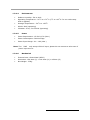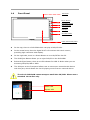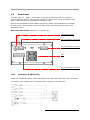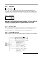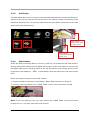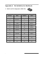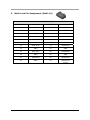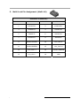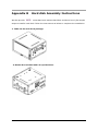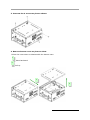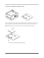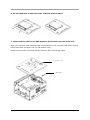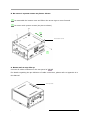
1
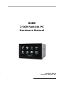
X400 X400 VPC6500 2-DIN Vehicle PC Hardware Manual Hardware Manual November 2009, Ver. A.3 VPC6500 Series Vehicle PC Hardware Manual A.3 1 Copyright This document by the original manufacturer is copyrighted © 2009, and all rights are reserved. The original manufacturer reserves the right to make improvements to the products described in this manual at any time without notice. No part of this manual may be reproduced, copied, translated or transmitted in any form or by any means without the prior written permission of the original manufacturer. Information provided in this manual is intended to be accurate and reliable. However, the original manufacturer assumes no responsibility for its use, nor for any infringements upon the rights of third parties that may result from such use. Copyright © 2009 by original manufacturer, All rights reserved. November 2009, Version A.3 Acknowledgments AMI is a trademark of American Megatrends Inc. (AMI). VIA is a trademark of VIA Technologies, Inc. IBM, PC/AT, PS/2 and VGA are trademarks of International Business Machines Corporation. Intel, Pentium, Celeron, and MMX are registered trademarks of Intel Corporation. Microsoft Windows® is a registered trademark of Microsoft Corp. RTL is a trademark of Realtek Semi-Conductor Co., Ltd. All other product names or trademarks are properties of their respective owners. X400 Vehicle PC, please For more information, technical support and service about this VPC6500 contact your supplier where you have purchased from. This manual is for VPC6500 the X400 series (Ver. A.3, November, 2009) VPC6500 Series Vehicle PC Hardware Manual A.3 2 Announcement X400 This manual is only written for the VPC6500 Vehicle PC series product with supporting Windows based operating system use. The appropriate models for this user’s manual are in the following list. VPC6500 series X400 Series Limited Warranty This product is warranted against manufacturing defects for the period of 1 year. During one-year warranty period, defective parts will be repaired or replaced. There will be no charge for labor or parts. This warranty does not cover any failure resulting in loss to software, data, lost profits, lost savings, any incidental damages or other economic consequential damages due to accident, abuse, misuse, negligence and acts of God. VPC6500 Series Vehicle PC Hardware Manual A.3 3 Safety Notice We make no warranties with respect to this documentation and disclaim any implied warranties of merchantability and fitness for a particular purpose. We shall not be liable for any error or for incidental or consequential damages in connection with the furnishing, performance, or use of this documentation or the examples herein. The information in this documentation is subject to change without notice. 1. This equipment should not be exposed to water or other liquids. 2. Do not cover the openings; the openings on the equipment are for air convection hence protects the equipment from overheating. 3. Do not attempt to remove the cover of this equipment. 4. If any of the following situations arises, have the equipment checked by an authorized service personnel: • The USB connector is damaged. • The power cord or connector is damaged. • Liquid has penetrated into the equipment. • The equipment has obvious sign of breakage. Observe the following warnings when installing this unit. 1. Only a qualified professional may install or repair this unit, please contact your local dealer for installation or repairing. 2. Use 12 VDC power supply only. This product is designed for operation with a negative grounded 12 VDC battery system. Never operate this product with other battery systems, especially a 24 VDC battery system. 3. Check for piping, gasoline tank, electric wiring, and other items before installing the product. 4. Do not use safety-related vehicle components (fuel tank, brake, suspension, steering wheel, pedals, airbag, etc.) for wiring or fixing the product or its accessories. 5. Installing the product on the air bag cover or in a location where it interferes with airbag operation is prohibited. 6. In the case of installation to an airbag equipped car, confirm warnings and cautions of the vehicle manufacturer before installation. 7. Without guidance of technicians, it is not allowed to replace the fuse of power supply. Use of an improper fuse will damage the device or lead to smoke or fire. 8. Do not use the product where it may expose to water, moisture, or dust. Exposure of the unit to water, moisture, or dust may lead to smoke, fire, or other damage to the VPC6500 Series Vehicle PC Hardware Manual A.3 4 unit. 9. Do not cover the openings; the openings on the equipment are for ventilation hence protects the equipment from overheating. 10. Never install the product in a location where it interferes with your field of vision. 11. Never have the power wire branched to supply other equipment with power. 12. After installation and wiring, you should check the normal operation of other electrical equipment. 13. Make sure the leads do not interfere with driving or getting in and out of the vehicle. 14. Isolate all exposed wires to prevent short circuiting. Observe the following cautions when installing this unit. 1. Refer wiring and installation to qualified service personnel. Installation of this unit requires special skills and experience. For maximum safety, have it installed by your dealer. We’re not liable for any problems resulting from your own installation of the unit. 2. Follow the instructions to install and wire the product. Not following the instructions to properly install and wire the product could cause an accident or fire. 3. Take care not to damage the leads when wiring. Prevent them from getting caught in the vehicle chassis, screws, and moving parts such as seat rails. Do not scratch, pull, bend or twist the leads. Do not run them near heat sources or place heavy objects on them. If leads must be run over sharp metal edges, protect the leads by winding them with vinyl tape or similar protection. 4. Use the supplied or designated parts and appropriate tools to install the product. The use of parts other than those supplied or designated may result in internal damage to the unit. Faulty installation may lead to an accident, a malfunction or fire. 5. Do not install the product where it is exposed to strong vibrations or is unstable. Avoid slanted or strongly curved surfaces for installation. If the installation is not stable, the unit may fall down while driving and this can lead to an accident or injury. 6. Do not expose the unit to direct sunlight or excessive heat. Otherwise these will raise the interior temperature of the unit, and it may lead to smoke, fire, or other damage to the unit. 7. Do not block the air vent or the cooling plate of the unit. Blocking these parts will cause the interior of the unit to overheat and will result in fire or other damage. 8. Wear gloves for safety. Make sure that wiring is completed before installation. 9. To prevent damage to the unit, do not connect the power connector until the whole wiring is completed. The user should bear in mind that in some areas there may be restrictions on how and where this unit must be installed. Consult your dealer for further details. VPC6500 Series Vehicle PC Hardware Manual A.3 5 Packing List Before you begin installing your unit, please make sure that the following materials are included in the packing: • 1 x VPC6500 X400 Vehicle PC main system • 2 x CD (User Manual & Driver CD) • 1 x Yellow card • External cable kit with multi-lock connectors in 3 pieces (in a inner box) If any of these items are missed or damaged, contact your distributor or sales representative immediately. Additional Information Contact your distributor, sales representative, or customer service center for technical support if you need additional assistance. Please have the following information ready before you call: • Product name and serial number • Description of your peripheral attachments • Description of your software (e.g. operating system, version, and application software… etc.) • A complete description of the problem • The exact wording of any error messages VPC6500 Series Vehicle PC Hardware Manual A.3 6 Table of Content Copyright .................................................................................................... 2 Acknowledgments ........................................................................................... 2 Announcement ................................................................................................ 3 Limited Warranty ............................................................................................ 3 Safety Notice................................................................................................... 4 Packing List .................................................................................................... 6 Additional Information .................................................................................... 6 Chapter 1 Introduction.................................................................................... 8 1.1 Introduction ........................................................................................ 8 X400 features............................................................................... 8 1.2 VPC6500 1.2.1 Vehicle Use................................................................................ 8 1.2.2 Car Stereo ................................................................................ 8 1.2.3 MultiLock Connection .................................................................. 8 1.2.4 Windows O/S ............................................................................. 9 1.2.5 Multimedia Graphic User's Interface.............................................. 9 1.2.6 Support GPS System (external device) .......................................... 9 1.2.7 Wireless Network ....................................................................... 9 1.2.8 Bluetooth.................................................................................. 9 1.2.9 Smart Power ............................................................................. 9 1.3 General Specifications......................................................................... 10 1.3.1 Processor................................................................................ 10 1.3.2 Memory .................................................................................. 10 1.3.3 Storage (Optional) ................................................................... 10 1.3.4 I/O Connector ......................................................................... 10 1.4 Front Panel.......................................................................................... 12 1.5 Rear Panel........................................................................................... 13 1.5.1 Connector A (Multi-40) .......................................................... 13 1.5.2 Connector B (Multi-24) .......................................................... 14 1.5.3 Connector C (Multi-16) .......................................................... 16 1.6 Side view............................................................................................. 16 Chapter 2 Installation for external device ..................................................... 17 2.1 Introduction ........................................................................................ 17 2.1.1 USB /SD card devices..................................................................... 17 2.1.2 Audio output ................................................................................. 18 2.1.3 USB GPS installation ...................................................................... 18 2.1.4 Hand Braking............................................................................... 19 2.1.5 AUX Input ................................................................................... 20 2.1.6 CCD Camera ................................................................................ 20 2.1.7 Side Marker ................................................................................. 21 Appendix A Pin Definition for MultiLock ....................................................... 22 1. Multi-Lock Pin Assignment (Multi-40) ................................................. 22 2. Multi-Lock Pin Assignment (Multi-24) ................................................. 23 3. Multi-Lock Pin Assignment (Multi-16) ................................................. 24 Appendix B Hard disk Assembly Instructions............................................... 25 VPC6500 Series Vehicle PC Hardware Manual A.3 7 Chapter 1 Introduction 1.1 Introduction VPC6000 The X400 series Vehicle PC is the best 2-DIN Car PC solution in the market. The all-new design improved 2-DIN features to be more friendly and easy-to-use. It’s embedded with car radio and built-in 5.1 channels amplifier with high-end sound stage simulation. The front panel of the 2-DIN Car PC embeds a digital 6.95” LCD touch screen that provides 800 x 480 high resolution display that releases driver’s weariness. Combined with multimedia entertainment system, it allows you using computing features in car such as GPS navigation, WiFi/Bluetooth communication, Movie/ Music/ Photo playing, EQ control and smart power control…etc., by simply few touch clicks. All combination in the unit fulfills car specification and it’s especially designed to meet harsh environment such as sustaining extreme shock, vibration and high temperature operation. VPC6500 The X400 brings you a vehicle infotainment computing runway whole the driving. The manual introduces hardware features and its operation instructions. Please read carefully and the manual will guide you with more hardware description and installation. 1.2 X400 Features VPC6500 features 1.2.1 Vehicle Use • Vehicle-specific computer system • 12 VDC power ready • Suit to vehicle environment • 2-DIN size with user friendly access buttons at front panel 1.2.2 Car Stereo • 35W x 5 + Subwoofer output x 1 • FM and AM radio tuner embedded • 18 FM/9 AM stations present 1.2.3 MultiLock Connection • Standard vehicle use • Secure data transferring • Easy to connect and disconnect VPC6500 Series Vehicle PC Hardware Manual A.3 8 1.2.4 Windows O/S • Microsoft Windows XP Embedded • Support Windows bases application 1.2.5 Multimedia Graphic User's Interface • Support media files playback • Support software programs access • Hands-free phone feature • Music/Movie/Photo playback • Flexible sound stage adjusting(EQ, audio output) • GPS navigation • WiFi/3G/Bluetooth communication • Support digital TV • Support web browser • Intelligent system settings 1.2.6 Support GPS System (external device) • USB GPS receiver supported (optional) • Support Navigation software 1.2.7 Wireless Network • Internet connection • Web browse 1.2.8 Bluetooth • Input device connectivity • Support hands-free phone features 1.2.9 Smart Power • Intelligent power control system • Automatically power on/off with delayed time function VPC6500 Series Vehicle PC Hardware Manual A.3 9 1.3 General Specifications 1.3.1 Processor • 1.3.2 • 1.3.3 • 1.3.4 Intel Mobile Celeron M Memory SODIMM x 1(1GB up to 2GB) Storage (Optional) SATA 2.5" HDD I/O Connector 1.3.4.1 Front Panel • 1 x DVD ROM • 1 x USB Port • 1 x SD Card Slot (supports SDHC) • 1 x AUX input (2.5mm wide) 1.3.4.2 Back Panel • 1 x VGA Output (For 2nd external display) • 4 x USB Port • 1 x MIC-in • 1 x CCD (RCA) • 1 x Reverse control wire • 1 x AV input (RCA cable, including one video input and two audio input) • 1 x Hand Brake (control wire) • 1 x side marker • 6 x audio output • 1 x line out (left, right) • 1 x Power cable (ACC wire x 1; Battery x 1; GND x 1) 1.3.4.3 LCD Panel • 6.95" with touch screen • 16:9 Aspect • LED back light • 400 nits light • Touch Panel Operation • Wide range temperature of -30˚C to +85˚C VPC6500 Series Vehicle PC Hardware Manual A.3 10 1.3.4.4 Environment • Relative Humidity: 5% to 90% • Operating Temperature: -20˚C to +70˚C (0˚C to +45˚C if a non-wide-temp HDD is applied) • Storage Temperature: -30˚C to +85˚C • Shock: 80G (operating) • Vibration: 2.0G, 5 to 500Hz (operating) 1.3.4.5 Power • Power Requirement: 12 VDC @ 7A (Max.) • Power Consumption: 36W Average • Power Input Range: 9V ~ 16V (Max.) X400 only accept 12V ACC input; please do not connect to other sort of Note: The VPC6500 power input source. 1.3.4.6 Mechanical • External case: Sheet Metal (SECC) • Dimension: 184.4mm (L) x 104.4mm (H) x 168mm (D) • Net Weight: 3.5Kg VPC6500 Series Vehicle PC Hardware Manual A.3 11 1.4 Front Panel DVD ROM Power Button DVD Eject Button HDD Indicator Aux Input USB port SD Card Reader 6.95” LCD touch panel z On the top, there is a DVD ROM which can play a DVD/CD disc. z In the central area, there’s a digital 6.95” LCD monitor with touch screen, providing high resolution VGA display. z On the right side, there is a Power Button to turn On/Off the Car PC. z The DVD Eject Button allows you to eject DVD/CD in the DVD ROM. z Below the Eject Button, there is an LED indicator for HDD. It blinks when you are accessing DVD/CD/USB or HDD. z The AUX port on the front panel allows user to connect an external audio device with this port, which allows the Car PC playing music from an external device. The slot-in DVD ROM cannot accept a small-size CD/DVD. Please use a standard 12-cm disc only. Power LED Ejector LED (The X400LED LEDindicators) Indicators) (VPC6500 VPC6500 Series Vehicle PC Hardware Manual A.3 12 1.5 Rear Panel The rear panel of VPC6500 X400 comes with external I/O connectors for connecting to various external devices, such as LCD monitor or USB drives. Those connectors work with a cable kit which is provided for evaluation only. For the best performance and reliable connection, please use the MultiLock connector for both ends. The following sections list each of the external I/O connectors with detailed function. Rear side dimensions: 180mm (L) x 100mm (H) Antenna for Radio 16-pin MultiLock connector 24-pin MultiLock connector Fan 40-pin MultiLock connector 1.5.1 Connector A (Multi-40) There are 4*USB connectors, VGA, Microphone input with this connector. The connection is located on the middle left of rear panel that is mainly for PC features. VPC6500 Series Vehicle PC Hardware Manual A.3 13 1.5.1.1 4*USB ports The VPC6500 X400 series provides 1 USB port on front panel and 4 more USB ports for connecting external USB devices with Multi-Lock connector from the rear panel. These USB ports are USB 2.0 compliant. They can also be disabled from the system BIOS setup. 1.5.1.2 VGA output The VPC6500 currently uses VGA firmware to fix the resolution of 2nd display at X400 800 x 600 for perfect display. We strongly recommend users not to adjust the resolution from windows platform. We cannot guarantee if user adjust resolution out of 800 x 600. 1.5.1.3 Microphone input When user needs to use microphone, please find mic-in connector from the rear panel. It can be extended to the front panel or to the rear seat of a car, so that the driver or passengers may use it to record or speak with hands-free phone feature. 1.5.2 Connector B (Multi-24) In this connector set, there are connections for power pins, AUX input, CCD input, and handbrake (parking brake). BLUE/WHITE VPC6500 Series Vehicle PC Hardware Manual A.3 14 1.5.2.1 Power connection The cables should be connected to vehicle power cable. Users may follow the instructions to complete the connection. Pins to Battery The power input connectors carries out the power input of 9~16 VDC, with yellow wires to Battery+ and black wires to Battery-. Pins to ACC The Red wire is supposed to be connected to ACC ignition, and the black ground wire needs to be connected to car body. 1.5.2.2 CCD Camera (CCD Back) The CCD Back allows user to connect rear-view CCD camera, follow the CCD connecting label to connect the CCD wire, so that you can enable the CCD camera with an RCA input. 1.5.2.3 Hand Braking According to regulation of international laws, a driver may not use electrical product while driving. The operation can only be used when the parking brake is pulled up. Therefore the wire has to be connected to the parking brake of a car. 1.5.2.4 AUX Input When the driver and passengers want to listen to music not only from local HDD or attached DVD, it offers you another choice of connecting your external devices from AUX inputs. With this function, the VPC6500 can play audio/Video from connected analog X400 devices. VPC6500 Series Vehicle PC Hardware Manual A.3 15 1.5.3 Connector C (Multi-16) VPC6500 The X400 provides 5.1 Channel audio outputs with this connection. User can follow the diagram to connect related cables. 1.6 Side view (Left Side) (Right Side) Depth: 168.1mm Dimensions: 184.4mm (L) x 104.4mm (H) x 168.1mm (D) VPC6500 Series Vehicle PC Hardware Manual A.3 16 Chapter 2 Installation for external device 2.1 Introduction VPC6500 The X400 provides Windows platform that enables easy attaching of external devices, such as USB devices, SD cards, and AUX inputs that allow easy access by Media Monsuta user interface. The following sections will guild you how to install the external devices. Please read it carefully. 2.1.1 USB /SD card devices The VPC6500 provides five USB ports and one SD card reader to share media/data files X400 from the external devices (refer to Photo I and II to see the connection of USB device). Once the USB devices or SD card is detected, Media Monsuta will check them as one of the X400. storage (refer to photo III) of VPC6500. While playing movie/music/photo files, you may select files from those devices via Media Monsuta GUI. (Photo I) (Photo II) USB DISK (Photo III) VPC6500 Series Vehicle PC Hardware Manual A.3 17 2.1.2 Audio output 2.1.2.1 5.1 channels audio output VPC6500 The X400 provides 5.1 channel audio outputs. This 5.1 channel outputs are defined with Subwoofer, Front-left, Front-right, Central, Rear-left, and Rear-right. Users may follow the indications on the label to connect. X400 Note: The central channel of VPC6500 can not be connected to an active speaker. Otherwise, it may damage the speaker. 2.1.3 USB GPS installation The X400 provides USB ports to support different USB devices, such as a USB GPS receiver. VPC6500 The installed GPS receiver can work with its drivers and the navigation software to provide X400. GPS navigation with VPC6500. X400's USB port (you may connect to USB port on Simply connect GPS receiver to VPC6500’s front, or rear USB port from the cables), and then install its driver as you normally install it in windows environment. Note: The GPS receiver is an optional accessory for VPC6500. Please contact your sales X400. representative to acquire the device if navigation function is required. VPC6500 Series Vehicle PC Hardware Manual A.3 18 2.1.4 Hand Braking According to regulation of international laws, a driver may not use electrical products while driving. The car PC can only be used when the parking brake is on. Therefore, some X400 are not allowed to use while driving. The control wire for applications of the VPC6500 parking brake allows users to enable or disable some functions with the parking brake’s on or off. If you need to enable the limited features when you test the VPC6500 X400 in the lab, you may connect brown “hand braking" wire to the black Ground (GND) wire. The result will be seen on the main page of Media Monsuta User Interface. When you short the two wires, you will see some disabled icons on this UI are enabled. (For more information, please refer to Media Monsuta operation manual.) VPC6500 Series Vehicle PC Hardware Manual A.3 19 2.1.5 AUX Input The AUX inputs allow users to connect external audio/video devices such as mp3 device or analog TV box. On the rear panel the AUX input in the cable kit allows connection to both video and audio devices; on the front panel the AUX input allows connection to an audio device only (see below figure). AUX1 can be connected to video or audio device. AUX2 can be connected to audio device only. 2.1.6 CCD Camera Follow the CCD connecting label to connect it, and you can enable the rear CCD camera. Simply connect the CCD to the CCD-BACK (see Photo I) of the rear cable kit, and connect the REAR TURN to the reversing switch of the car. So that the rear images of the car will be shown on the display of VPC6500 X400 automatically when the shift level is put into reverse level. Below are steps to connect a rear CCD camera: 1. Camera should be connect to "CCD-BACK" (Black RCA Connector as photo I) 2. Connect reversing switch “R” to “REAR TURN" (color: brown and white mixed) (Photo I) Note: If you are testing in lab, you may connect the “REAR TURN" (brown and white mixed) wire to +12V wire (blue and white mixed). VPC6500 Series Vehicle PC Hardware Manual A.3 20 2.1.7 Side Marker Side marker is a signal wire connecting to the head light of the car. After you connect them to the head light wire, the back light of VPC6500 X400 LCD panel will automatically switch to become softer when the head light is on. The feature is to prevent the driver distracted when driving in the dark. Note: If you are testing in lab, you may connect “Side Marker” to “SYS +12V 0.5A” to soften the back light of the LCD. VPC6500 Series Vehicle PC Hardware Manual A.3 21 Appendix A Pin Definition for MultiLock 1. Multi-Lock Pin Assignment (Multi-40) Connector A (Multi-24) PIN No# Name PIN No# Name 1 VGA-GND 2 VGA-Blue 3 VGA-Hsync 4 VGA-Green 5 VGA-Vsync 6 VGA-Red 7 N/C 8 N/C 9 N/C 10 N/C 11 A-GND 12 MIC-In - 13 USB-PW3 14 USB-P3+ 15 USB-GND 16 USB-P3- 17 USB-PW2 18 USB-P2+ 19 USB-GND 20 USB-P2- 21 USB-PW1 22 USB-P1+ 23 USB-GND 24 USB-P1- 25 USB-PW0 26 USB-P0+ 27 USB-GND 28 USB-P0- 29 N/C 30 N/C 31 N/C 32 N/C 33 N/C 34 N/C 35 N/C 36 N/C 37 N/C 38 N/C 39 N/C 40 N/C VPC6500 Series Vehicle PC Hardware Manual A.3 22 2. Multi-Lock Pin Assignment (Multi-24) Connector B (Multi -24) PIN No# Name PIN No# Name 1 BATT+ 2 BATT- 3 BATT+ 4 BATT- 5 BATT+ 6 BATT- 7 ACC 8 MARKER LIGHT 9 HAND BRAKING 10 CCD-BACK 11 Rear Turn 12 CCD-GND 13 AUX-IN_R 14 RESERVED 15 GND 16 GND 17 AUX-IN_L 18 RESERVED 19 GND 20 GND 21 VIDEO-IN 22 RESERVED 23 GND 24 System RC (0 5A) VPC6500 Series Vehicle PC Hardware Manual A.3 23 3. Multi-Lock Pin Assignment (Multi-16) Connector C (Multi-16) PIN No# Name PIN No# Name 1 AUDIO-FR+ 2 AUDIO-RR+ 3 AUDIO-FR- 4 AUDIO-RR- 5 AUDIO-FL- 6 AUDIO-RL+ 7 AUDIO-FL+ 8 AUDIO-RL- 9 AUDIO-CENTER- 10 Line_Out R- 11 AUDIO-CENTER+ 12 Line_Out R+ 13 Line_Out L+ 14 AUDIO-WOOFER 15 Line_Out L- 16 GND VPC6500 Series Vehicle PC Hardware Manual A.3 24 Appendix B Hard disk Assembly Instructions We also provide VPC6500 X400 series bare bone without hard disk, and there’re only few simple steps to install a hard disk. Follow the instructions as below to complete the installation. 1. Take out the unit from package. 2. Rotate the unit and make it up side down. VPC6500 Series Vehicle PC Hardware Manual A.3 25 3. Unscrew the 4 screws as picture shown. 4. Remove bottom cover as pictures show. Follow the instructions to disassemble the bottom case. 1 Move backward 2 Pull up 1 2 VPC6500 Series Vehicle PC Hardware Manual A.3 26 5. Prepare to install HDD on the bottom cover. There is a hard disk bracket (with 4 hookers and protectors) on the bottom case to fix the hard disk. Make sure the location of the hard disk to fix it (as bellow picture shown). Note: Please make sure the hard disk is on the correct position before fixing it. Here is arrow sign indicating the head of hard disk. VPC6500 Series Vehicle PC Hardware Manual A.3 27 6. Fix the HDD with 4 defined screws as below pictures show. 7. Connect SATA cable to the HDD between the bottom case and main unit. After you complete hard disk assembly on the bottom cover, connect HDD cable to each end of hard disk and main unit (on the bottom case). Please mind that the connector has its direction while connecting cable. The bottom cover HDD cables VPC6500 Series Vehicle PC Hardware Manual A.3 28 8. Re-screw 4 system screws as picture shows 1 2 Re-assemble the bottom case and follow the arrow sign to move forward. Re-screw with system screws (As picture shows). 1 The bottom cover 2 9. Rotate unit to top side up. Connect all cables indicates on the rear panel of VPC6500. X400. For details regarding the pin definition of cable connection, please refer to Appendix A in this Manual. The top case VPC6500 Series Vehicle PC Hardware Manual A.3 29