1
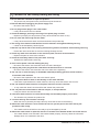
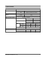
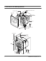
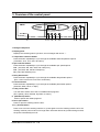
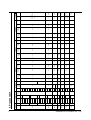
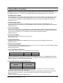
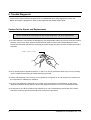
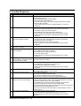
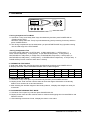
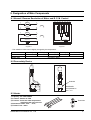
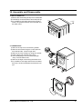
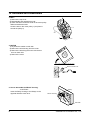
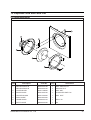
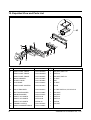
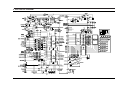
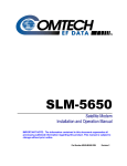
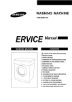
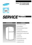
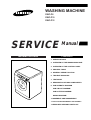
WASHING MACHINE
SWF-P8
SWF-P10
SWF-P12
SERVICE
WASHING MACHINE
Manual
CONTENTS
1. SPECIFICATIONS
2. OVERVIEW OF THE WASHING MACHINE
3. OVERVIEW OF THE CONTROL PANEL
4. PROCESS TABLE
5. GENERAL REEOR FUNCTION
6. TROUBLE DIAGNOSIS
7. TEST MODE
8. DESIGNATION OF MAIN COMPONENTS
9. PCB SHEMATIC DIAGRAM
PCB CIRCUIT DIAGRAM
PCB PATTERN DIAGRAM
WIRING DIAGRAM
10.ASSEMBLE AND DISASSEMBLE
11.TOOLS FOR DISASSEMBLY AND ASSEMLY
12.EXPOLDED VIEW AND PARTS LIST
! Caution for the safety during servicing
1. Do not allow the customer to repair the product.
☞ The person may be injured or the product life may be shortened.
2. Execute A/S after unplugging the power supply unit.
☞ Be care of the electric shock.
3. Do not plug several plugs in the same outlet.
☞ It may cause the fire due to overheat.
4. Check the damage, pressing or burning of the power plug or outlet.
☞ Replace it promptly if it has problem.(It may cause the electric shock or fire)
5. Do not clean the main body with the water.
☞ It may cause the electric shock and fire and shorten the product life)
6. The wiring of the harness shall be free from the moisture and tightened during serving.
☞ It shall not be deviated by certain impact.
7. Remove any dust or filth on the housing section,wiring section,connection section during servicing.
☞ Protect the cause of the fire such as the tracking,shortage and etc.
8. Check any mark of the moisture on the electrical parts, harness section and etc.
☞ Replace the parts or remove the moisture.
9. Check the assembly status of the parts after servicing.
☞ Maintain the status before servicing.
10. Pull out the power cord with holding the plug.
☞ Be care of the electric shock and fire when the cord is damaged.
11. Unplug the power plug from the outlet when the wash machine is not used.
☞ Be care of the electric shock and fire due to the strike of the lightening.
12. Do not use or store the spray or flammable materials(including gasoline,alcohol and etc.)
around the wash machine.
☞ Be care of the explosion or fire due to the electric spark.
13. Do not put the bowl of water or wet laundry on the wash machine.
☞ If the water is penetrated to the wash machine, this may cause the electric shock or fire.
14. Do not install the wash machine in the place where the snow or rain falls.
☞ It may cause the electric shock and fire and shorten the product life.
15. Do not push the control buttons with the awl,pin, or sharp materials.
☞ It may the electric shock and trouble.
16. Check the wash machine is leveled horizontally and installed properly on the floor.
☞ The vibration may shorten the product life.
17. Joint the wire by the connector correctly.
☞ When the wire is jointed by the tape, this may cause the fire due to the tracking.
18. When the wash machine is to be laid for the service, put the pad on the floor and lay the
product at side slowly.
☞ If the wash machine is laid front, the relay may be damaged by the tub.
19. When the wash-heater is replaced, check it is inserted in the bracket-heater and screw the nut.
☞ If the wash-heater is not inserted in the bracket-heater properly, this may cause the noise and
leakage since it is contacted to the drum.
2
SAMSUNG ELECTRONICS CO., LTD
1. Specifications
WASH TYPE
FRONT LOADING TYPE
DIMENSION
GROSS
W 669mm X D 656mm X H 910mm
NET
W 598mm X D 555mm X H 844mm
WATER PRESSURE
50 kPa ~ 800 kPa
WEIGHT
GROSS
80 kg
NET
75 kg
WASHand SPIN CAPACITY
POWER CONSUMPTION
50 kg (DRY LAUNDRY)
WASHING
WASHING and HEATING
SPIN
220 V
180 W
240 V
180 W
220 V
2400 W
240 V
2800 W
MODEL
SWF-P8
SWF-P10
SWF-P12
220 V
430 W
500 W
550 W
240 V
430 W
500 W
550 W
PUMPING
WATER CONSUMPTION
SPIN REVOLUTION
SAMSUNG ELECTRONICS CO., LTD
34 W
54 (STANDARD COURSE)
MODEL
SWF-P8
SWF-P10
SWF-P12
rpm
800
1000
1200
3
2. Overview of the Washing Machine
CONTROL-PANEL
WATER SUPPLY VALVE
DRAWER
ASSY DOOR
SENSOR
PRESSURE
TUB
ADJUSTABLE LEG
ASSY PUMP
POWER CORD
BUFFER
SPRING
WEIGHT-BALANCE
DRAIN
HOSE
PULLEY
BELT
ASSY MOTOR
4
SHOCK
ABSORBER
SAMSUNG ELECTRONICS CO., LTD
3. Overview of the control panel
Cotton
Remaining Time
Synthetic
Pre-wash
o
12:00
Check
C
rpm
Min
Wash
Rinse
Delay Start
Spin
Delicate
Wool
Speedy
Eco
Fuzzy control
Temp
1
2 3
Spin
4
Delay Start
5
Door open
Function
6
7 8
9 10
1. Detergent dispenser
2. Display panel
Displays the remaining wash cycle time, error messages and cancel —.
3. Temperature selection button
Press the button repeatedly to cycle through the available water temperature options
(cold water, 30°C, 40°C, 60°C and 90°C).
4. Spin selection button
Press the button repeatedly to cycle through the available spin speed options
P12 : (400, 600, 800, 900, 1000, and 1200 rpms.),
P10 : (400, 600, 800, 900 and 1000rpms),
P8 : (400, 600 and 800 rpms).
5. Delay Start button
Press the button repeatedly to cycle through the available delayed start options
(from 1 hour to 24 hours in one hour increments).
6. Function button
Press the button repeatedly to cycle through the available partial wash options
(Prewash, Wash, Rinse, or Spin).
7. Fuzzy Control dial
Turn the dial to select one of the six available wash programs
(Eco, Speedy, Wool, Delicate, Synthetic or Cotton).
8. (Start/Pause) button
Press to pause and restart programs.
9. Door Open button
Press to open the washing machine door.
10. 1) (On/Off) button
Press once to turn the washing machine on, press again to turn the washing machine off. If the
washing machine power is left on for longer than 10minutes without any buttons being touched,
the power automatically turns off.
SAMSUNG ELECTRONICS CO., LTD
5
6
SAMSUNG ELECTRONICS CO., LTD
WATER SUPPLY
WASHING
RINSING 1
5.0
3.0
1.5
2.0
2.0
5.0
SPEEY
PRE
ECONOMY 1.5
WOOL
DELICATE
SYNTHETIC 2.5
COTTON
1.5
40
-
20min
40˚C
30˚C
COLD WATER
40˚C
O
X
O
X
30˚C
COLD WATER
X
O
COLD WATER
30˚C
O
X
O
30˚C
COLD WATER
40˚C
30˚C
-
-
-
-
-
15min
10min
10min
10min
10min
15min
15min
20min
10min
15min
10min
10min
-
15min
X
60˚C
COLD WATER
20min
X
40˚C
30˚C
-
25min
O
40min
50min
90˚C
O
50min
COLD WATER
60˚C
40˚C
30˚C
-
55min
35min
45min
45min
90˚C
X
O
COLD WATER
60˚C
40˚C
30˚C
-
50min
X
COLD WATER
30min
90˚C
40min
40min
45min
60˚C
O
X
40˚C
30˚C
COLD WATER
9/6
12 / 3
9/6
3 / 12
5 / 10
6/7
7/8
9/6
40
45
40
25
30
40
48
-
3min
3min
2min
2min
3min
4min
-
10 / 5
9 /6
3/7
6/7
7/8
8/5
-
850
600
200
400
850
850
-
60sec
6sec
60sec
40sec
60sec
100sec
-
45
40
25
30
40
45
-
2min
3min
1min
2min
3min
3min
COURSE LOAD WATER TEMP BOILING LAYER WASH WASHING REVERSE RINSE WATER INTERMEDIATE SPINNING REVERSE RINSE
(kg)
SELECT
SPINNING TIME WATER
rpm
TIME CURRENT
SPINNING
TIME
rpm
TIME
CURRENT
TIME
DIVISION
4. Process table
RINSING 2
RINSING 3
SPINNING
-
10 / 5
9/6
3/ 7
6/7
7/8
8/5
-
850
600
-
-
850
850
-
60sec
60sec
-
-
60sec
100sec
-
45
40
25
30
40
45
-
-
-
1min
2min
3min
3min
-
-
-
3/7
6/7
7/8
8 /5
-
-
-
-
-
850
850
-
-
-
-
-
60sec
100sec
-
-
-
25
30
40
45
150sec
60sec
100sec
100sec
7’40’
850
P8:850
100sec
P12,10:1000 150sec
850
400
600
850
P8:850
P10:1000
P12:1200
WATER INTERMEDIATE SPINNING REVERSE RINSE WATER INTERMEDIATE SPINNING REVERSE SPINNING TIME
TIME
rpm
rpm
CURRENT
SPINNING
TIME
rpm
TIME CURRENT
SPINNING
TIME
TIME
5. General Error Function
•· When an error occurs, this function starts to keep generating error melody sounds and displays error
indicators as shown in the followings per corresponding error by blinking in 0.5sec interval until the error status
is completely cleared out. In this case, all the driving devices are turned off until the error is cleared out.
1. WATER SUPPLY ERROR
- Water Supply Error occurs when water level frequency does not show changes more than 50Hz or water
is not supplied up to the water level presetting for 20 min or more at the time of initial water supply, the
error status can be cleared by turning POWER S/W OFF and resuming the POWER ON initial status.
- Display shows ‘E1’.
2. WATER DRAIN ERROR
- In case the water level frequency is 25.3KHz or less in the initial phase of UNB-detecting cycle.
- Water Drain error can be cleared by turning POWER S/W OFF and resuming the POWER ON initial status.
- Display shows ‘E2’.
3. OVER-FLOW ERROR
- Over-Flow error occurs when the water level is in abnormal operation (OVER-FLOW: 22.40KHz/50ߧ or
more). It can be cleared by turning POWER S/W OFF. Water is drained prior to POWER S/W OFF and it
is forced to be drained for 2 min if a frequency of more than 25.24 KHz is detected.
- Display shows ‘E3’.
4. DOOR OPEN ERROR
- Door Open error can be cleared by closing the door.
- Display shows ‘door’.
5. UNBALANCE ERROR
- Unbalance error is cleared by POWER S/W OFF and by resuming the POWER ON initial status.
- Display shows ‘E4’.
6. WATER HEATER ERROR
- In case the water temperature varies by 40°C or more in 5 min, or by 2°C or less in 10 min after heating is started.
- It can be cleared by turning POWER S/W OFF.
- Display shows ‘E5,E6’.
7. ASS’Y PRESSURE S/W ERROR
* Generated Frequency Signal of WATER LEVEL(W/L) S/W (KHz)
Lvevl
Low Level
High Level
Abnormal W/L Frequency
30.00 KHz
15.00 KHz
- If the same signal as the above table is detected for more than 5 seconds, it is a PRESSURE S/W Error.
- When the error occurs, perform the time-drain for 3 min and then turn off the water drain pump. Then the
display shows ‘E7’ as a pressure s/w error indicator.
8. ABNORMAL WATER TEMPERATURE ERROR
Course
Water Temp
Synthetic
Delicate
Wool
60˚C or more
50˚C or more
40˚C or more
- In case the water temperature is 60°C or more in the synthetic course, 50°C or more in the delicate
course, and 40°C or more in the wool course.
- At the time of initial water supply, if the water temperature is not appropriate, water starts to be drained
and it is forced to be drained for 2 min when the abnormal frequency of 25.24KHz is detected.
- Display shows ‘E8’.
- This error can be cleared by POWER S/W OFF.
SAMSUNG ELECTRONICS CO., LTD
7
6. Trouble Diagnosis
°· As the micom wash machine is configured of the complicate structure, there might be the service call.
Below information is prepared for exact trouble diagnosis and suitable repair guide.
Caution for the Repair and Replacement
Please follow below instruction for the trouble diagnosis and parts replacement.
1) As some electronic components are damaged by the charged static electricity from the resin part of wash
machine or the human body, prepare the human body earth or remove the potential difference of the
human body and wash machine by contacting the power supply plug when the work contacting to PCB is
executed.
POWER SUPPLY PLUG
2) Since AC220~240V is applied to the triac T1 and T2 on P.C.B, the electric shock may occur by touching
and be careful that the strong and weak electricity are mixed.
3) If the P.C.B assembly is out of order, do not replace the component on P.C.B except TACT switch since
the component is coated by the urethane.
4) As the P.C.B assembly is designed for no trouble, do not replace the P.C.B assembly by the wrong
diagnosis and follow the procedure of the trouble diagnosis when the micom is not operated normally.
5) As the parts on P.C.B are coated by the urethane, they can not be tested by the test bar of the meter.
Check the trouble by the test mode method according to the procedure.
8
SAMSUNG ELECTRONICS CO., LTD
6. Trouble Diagnosis
No
Item
1
The power is not supplied
2
The water is not supplied.
3
The wash does not start though
the water supply is stopped.
4
The wash is executed while
the water is supplied.
The drum does not rotate
during washing.
5
6
7
The drum rotates by one direction
during washing. (The drum rotates
to one direction for SPIN.)
Drainage problem.
8
Dehydration problem.
9
Abnormal noise during SPIN.
10
Leak breaker or current/leak
breaker is down during washing.
11
The heating is not executed.
SAMSUNG ELECTRONICS CO., LTD
Cause and treatment
- Is the PCB connector connected well?
- Is the voltage normal?
- Is the power supply plug connected well?
- Is the noise filter connected well?
- Is the secondary output of the power supply transformation normal?
- Is the fuse disconnected?
• If above points are not found, the PCB assembly is out of order.
Replace it.
- Is the knob open?
- Did you push START/PAUSE button after selecting the course?
- Is the water supply valve connected well?
- Is the winding of the water supply valve continuous?
- Is the connection and operation of the pressure switch normal?
• If above points are not found, the PCB assembly is out of order.
Replace it.
- Is the connection and operation of the pressure switch normal?
- Is the pressure switch hose damaged so that the air is leaked?
- Is the pressure switch hose bent?
- Check the operation of the water level switch.
• If above points are not found, the PCB assembly is out of order.
Replace it.
- The PCB assembly is out of order. Replace it.
- Is the belt connected well?
- Is the winding of the motor continuous?
(Rotor winding, stator winding, generator)
- Is the motor fuse normal?
• If above points are not found, the PCB assembly is out of order.
Replace it.
- The PCB assembly is out of order. Replace it.
(Inversion relay open trouble)
- Is the drainage hose bent?
- Is the winding of the drainage pump continuous?
- Is the drain filter clogged by the waste?
• If above points are not found, the PCB assembly is out of order.
Replace it.
- The unbalance is detected.
- Put in the laundry uniformly and start again.
- Is the pulley nut loosen?
- Is the transport safety device removed?
- Is the product installed on the level and stable place?
(Little noise may be generated during the high-speed SPIN.)
<When the leak breaker and current breaker is installed separately>
- When the leak breaker is down, check and make the earth of the outlet.
- When the current is down, the current is leaked.
<Is the breaker down when the leak/current breaker is combined?>
- Check the rated capacity of the current and leak breaker.
The current breaker may be down due to the lack of the current when the
wash machine and other apparatus are used.
In this case, execute the cold water wash to check whether the current
capacity is lack.
- Is the wash heater terminal unplugged?
- Is the wash heater normal?(Resistance value : 20.5~21.5Ω)
- If above points are not found, the PCB assembly is out of order.
Replace it.
9
7. Test Mode
Cotton
Remaining Time
Synthetic
Pre-wash
o
12:00
Check
C
rpm
Min
Delay Start
Delicate
Wash
Rinse
Spin
Wool
Speedy
Eco
Fuzzy control
Temp
Spin
Delay Start
Door open
Function
1. Driving Compartment Test Mode
A. Hold down “Temp” and ”Delay Start” keys simultaneously and then press POWER S/W on.
(Display shows “tESt”)
Hold down “Delay Start” and “Temp” keys simultanesously (each processing for 0.3sec) and then
press POWER S/W on.
B. The driving compartment can be tested when you press START/PAUSE key right after entering
into the intial stage of the TEST MODE.
• Driving Compartment Test
Pre-wash VALVE ON(0.3sec) ➔ OFF(0.3sec) ➔ Main wash(0.3sec) ➔ OFF(0.3sec) ➔
Rinse VALVE ON(0.3sec) ➔ OFF(0.3sec) ➔ Spin MOTOR ON(0.3sec) ➔ OFF(0.3sec) ➔
MOTOR RELAY1 ON(0.3sec) ➔ OFF(0.3sec) ➔ MOTOR RELAY2(0.3sec) ➔ OFF(0.3sec) ➔
MOTOR RELAY2 ON(0.3sec) ➔ OFF(0.3sec) ➔ HEATER RELAY ON(0.3sec) ➔ OFF(0.3sec) ➔
DOOR OPEN (Function continues when door is closed)
2. THERMISTOR TEST MODE
A. Hold down “Delay Star” and Function keys simultaneously and then press POWER S/W on.
B. Display shows the current THERMISTOR data index in celsius degrees.
TEMP
DATA
TEMP
DATA
5
5
50
50
10
10
55
55
15
15
60
60
20
20
65
65
25
25
70
70
30
30
75
75
35
35
80
80
40
40
85
85
45
45
90
90
3. UNBALANCE TEST MODE
A. Hold down “Temp” and “Spin” keys simlitaneously and then press POWER S/W ON.
B. Display shows ”Unbt” and the machine starts to sense the degree of deviation of the laundry
balance for 9 minutes via 1st and 2nd setection.
C. After selecting the deviation degree of the laundry balance, it displays the data(in hex value) for
10 seconds.
4. LOAD AMOUNT SENSING TEST MODE
A. Hold down ”Door Open” key and then press POWER S/W ON.
B. Display shows ‘0000’ and the machine starts to measure the dropping time from 600 RPM to 100
RPM for 1minute.
C. After setecting the amount of load, it display the data in a hex value.
10
SAMSUNG ELECTRONICS CO., LTD
8. Designation of Main Components
8-1 Normal / Reverse Revolution of Motor and R. P. M. Control
8
Rotor
CW
9
-
+
CCW
5
Stator coil
ROTOR
10
PROTECTOR
(150 C)
Stator coil
MIDDLE-SPEED
5
1 2 3 4 5 6 7 8 9 10
+
STATOR
9
TACHO
Rotor
HIGH-SPEED
8
STATOR
10
5
WASHING MOTOR
<Figure1>
<Figure2>
• The resistance value can be slightly changed by the temperature.
Resistance value
Rated value
STATOR(5.10)
1.64 Ω
STATOR(5.1)
0.91 Ω
ROTOR(8.9) TACHO(3.4)
1.9 Ω
42.7 Ω
220~240V / 50Hz
PROTECTOR(6.7)
0
8-2 Door safety Device
Solenoid
220/240V
ED 1.0%
KB 1s
SD 100s
220/240V
ED 1.0%
KB 1s
SD 100s
12A 125~250V AC
SOLENOID
Coil Resistance
120 Ω ± 5
8-3 Heater
1) Capacity : AC 230V/2500W
2) Location : Bottom of TUB
3) Function : Raise the water temperature
supplied at the wash process.
4) Resistance value : 20.5Ω ~ 21.5Ω
5) Thermo Fuse : 128°C
SAMSUNG ELECTRONICS CO., LTD
Thermistor
11
10. Assemble and Disassemble
1. ASS’Y-COVER TOP
1) Remove two screws fixing the top-cover on back side.
2) Push the top-cover back about 15mm and pull it up.
3) It’s possible to exchange and service the trans
former, the pressure-senser, the noise-filter and
the water valve.
m
15m
SCREW
2. FRAME FRONT
1) Remove the top-cover and the ass’y drawer.
2) Remove two screws fixing the control-panel on
front side and the screw on right side.
3) Remove the cover-front(L) by using the (-)driver.
4) Pull the lever and open the ass’y-door.
5) Part the diaphragm and the wire diaphragm
away from the frame-front.
6) Remove the eight screws fixing the frame-front.
7) It’s possible to exchange and service the heater,
the pump, the shock-absorber and the door lock
s/w.
LEVER
SAMSUNG ELECTRONICS CO., LTD
15
10. Assemble and Disassemble
3. BELT
1) Remove the top-cover.
2) Disassemble and assemble the belt.
3) Check the belt is located at center of the motor-pulley.
<When assemble the belt>
Hook the belt on the motor pulley 1) and place it
around the pulley 2).
2
PULLEY
BELT
1
MOTOR
4. MOTOR
1) Lay down the washer on left side.
2) Remove the wire housing from the motor.
3) Remove the bolt fixing the motor with the box
drive on back side.
4) Remove the motor.
Motor Assemble Hole
5. How to Assemble the RELAY Housing.
<CAUTION>
Insert the Relay Housing to the Relays on the
opposite direation each other.
Relay
RELAY Housing
Heat Sink
16
SAMSUNG ELECTRONICS CO., LTD
11. Tools for Disassembly and Assembly
NO
1
2
TOOL
Box driver
10mm
Heater (1)
13mm
Motor (1), Balance (5)
17mm
2 holes of each left and right of the shock absorber
19mm
1 Pulley hole
Double-ended
10, 13
Replaceable for the box driver.
spanner
17, 19mm
Since the bolt runs idle when the box driver is used, use the box
driver 17mm.
3
Vice pliers
Tool to protect the idle and abrasion of the bolt for the box driver.
4
Other(Driver, Nipper, Long nose)
5
JIG for the Tub
General tools for the after service.
1 (Disassemble and Assemble)
10
19
13
8
12
17
10
mm
13
mm
17
mm
19
mm
SAMSUNG ELECTRONICS CO., LTD
17
12. Expolded View and Parts List
11
10
9
8
7
12
6
5
4
3
2
1
NO.
Description
Code No.
Q’ty
1
2
3
4
5
6
7
8
HEATER-WATER ELEMENT
TUB-FRONT
RBACKET-NUT
BRACKET-HEATER
SPACER-HEATER
VANE-CHECK
WASHER-PLAIN
ASS'Y-DRUM
ASS'Y-DRUM
ASS'Y-DRUM
PACKING-TUB
TUB-BACK
TUB-BACK
CLIP-TUB
CLIP TUB(P)
DC62-50123A
DC61-30346A
DC61-40348B
DC61-40344A
DC61-60496A
DC62-20311A
DC60-60044B
DC91-12281A
DC97-00785A
DC97-00785B
DC62-40183A
DC61-30347B
DC61-30347C
DC61-60499B
DC61-60520A
1
1
7
1
2
1
1
1
1
1
1
1
1
8
1
9
10
11
12
18
Secification
AISI-304L AC230V/2500W
PP(GR30%)IVORY
SBHG-R T3
STS430 T1
PBT
EPDM BLK
ID4.5 OD15.5 T1
SWF-P12
SWF-P8/P6091
SWF-P14,1400RPM/STS
EPDM BLK
PP(GR30%) IVORY,SWF-P12V
SWF-P6V
HSWR
SK5 ZPC3
SAMSUNG ELECTRONICS CO., LTD
12. Expolded View and Parts List
13
12
23
22
19
21
20
10
27
8
26
9
25
11
24
10
14
15
16
17
18
5
6
4
7
3
2
1
SAMSUNG ELECTRONICS CO., LTD
19
12. Expolded View and Parts List
NO.
Description
1
ASSY-WIRE DIAPHRAGM
DC91-12078A
1
2
DOOR-DIAPHRAGM
DC61-20219A
1
3
ASSY-CLAMP DIAPHGRAM
DC91-12077A
1
4
BOLT-W.MOTOR
DC60-40138A
2
M8 L70 ZPC2(YEL) SM10C
5
WASHER-PLAIN
DC60-60044B
5
ID8.4 OD13 T4.3 SBC
6
WASHER-NYLON
DC60-60040A
3
ID10.5 OD32 T2 PBSP-1/2H
7
WEIGHT-BALANCER
DC66-60154A
1
CONCRETE SWF-P12 LOWER
8
CLAMP-HOSE
DC61-60359D
1
HSWR
9
HOSE-DRAWER TUB
DC62-10305A
1
EPDM ID35 BLK L158
10
BOLT-HEX
DC60-40140A
2
M8 L140 ZPC2/YEL WEIGHT-UL/SM1
11
BOLT-FLANGE
DC60-40132B
1
M8 L205 ZPC2 SS41C
12
HOSE-AIR
DC62-10303A
1
EPDM ID24 BLK L130
13
WEIGHT-BALANCER
DC66-60153A
1
CONCRETE SWF-P12 UPPER
14
PACKING-TRAP
DC62-40184A
1
EPDM BLK
15
CAP-TRAP
DC61-10676A
1
PP(TB53)
16
CLAMP-HOSE
DC61-60497A
1
HSWR SWF-P12 ID70/OD75.8(TUB)
17
HOSE-FILTER TUB
DC62-10304A
1
EPDM ID65 BLK L151
18
BAND-RING
DC65-60118F
1
ID33
19
PULLEY
DC66-10176B
1
ALDC D297
20
WASHER
DC60-60060A
1
21
WASHER-SPRING
DC60-60049A
1
ID10.5 OD18 T2.5 SIR
22
NUT-HEX
DC60-50148B
1
HEXAGON M(12) ZPC2(YEL) SM10C
23
BELT-TRANSMISSION
DC66-10139B
1
24
MOTOR-DRUM
DC31-00002C
1
13000rpm 100Nm 220~240VDC 1.8A
25
CUSHION-MOTOR
DC61-00041A
2
NBR SWF-P12 ID13.4/OD28
26
BOLT-W.MOTOR
DC60-40138A
1
M8 L70 ZPC2(YEL) SM10C
27
PIN-SPLIT
DC60-80175A
2
ZPC2(YEL)SM10C
20
Code No.
Q’ty
Secification
EPDM GRY SWF-P10/P8/P12
SAMSUNG ELECTRONICS CO., LTD
12. Expolded View and Parts List
8
1
2
13
18
12
17
15
9
19
14
16
3
7
20
10
22
11
21
5
4
6
27
23
28
24
29
25
26
31
32
33
30
SAMSUNG ELECTRONICS CO., LTD
21
12. Expolded View and Parts List
NO.
Description
Code No.
Q’ty
Secification
1
ASS'Y-M.WIRE HARNESS
DC90-11153A
1
MAIN-WIRE(A)
2
ASSY-WIRE HARNESS
DC90-11181A
1
SUB
3
FRAME-PLATE(U)
DC61-30344A
1
EGI NTR
4
SENSOR PRESSURE
DC32-30006J
1
SEW-DK
5
CLAMP HOSE
DC61-60063B
1
SK5 YEL
6
HOSE PRESSURE
DC62-10311A
1
EPDM, SWF-P8/P10/P12
7
TRANS-FORMER
DC26-10150E
1
HSG 230V 12VDC 50/60HZ
8
ASSY-COVER TOP
DC91-12083A
1
9
FRAME-FRONT
DC61-30345A
1
EGI WHT
10
DOOR-LOCK S/W
DC61-20229A
1
230V/50HZ LTD
11
LEVER
DC66-30160A
1
PE*EVA L335
12
SPRING-HANGER
DC61-70216C
1
HSWR SWF-P12 LEFT(OD24)
13
SLEEVE-PLUG
DC61-60180A
3
NYLON#6
14
SPRING-HANGER
DC61-70217C
2
HSWR SWF-P12 RIGHT(OD30)
15
ASSY-VALVE WATER(C)
DC91-12279A
1
16
CLAMP-HOSE
DC61-60063B
6
SK5 YEL
17
HOSE-DRAWER
DC62-10068A
1
SOFT-PVC ID10 NTR L350
18
FILTER-EMI AC LINE
DC29-00003A
1
250V 15A UL/CSA 2200pF 50*63B
19
ASSY-POWER CORD
DC90-11099D
1
20
HOLDER-WIRE
DC61-40081A
5
NYLON66 DAWH-3NB(PI15)
21
HOSE-VINYL
DC62-10001H
1
VINYL ID4 NTR L870
HOSE-VINYL
DC62-10001E
1
VINYL ID4 NTR L940
22
ASSY-HOSE DRAIN(0)
DC97-00139A
23
ASSY-HOSE DRAIN(I)
DC91-10351C
1
ID25/BAND
24
BAND RING
DC65-60118F
1
PW1 PI23
25
PAINT
DC92-11206A
1
COLD/BUTTON-DOOR
26
ASSY-LEG
DC91-12292A
4
27
DAMPER-SHOCK
DC66-60149A
2
80N
28
BOLT-HEX
DC60-40026A
2
M10 SCP
29
COVER-FRONT(L)
DC61-10672A
1
PP(BJ-730) WHT
30
CAP-DRAIN
DC61-10673A
1
PP WHT
31
HOSE-DRAIN
DC62-10302A
1
EPDM ID5.5 BLK L220 OD9.5
32
ASSY-PUMP DRAIN
DC90-11110K
1
220/240V 50HZ
22
SAMSUNG ELECTRONICS CO., LTD
12. Expolded View and Parts List
1-1 Safety precautions
7
1
5
2
3
4
6
NO.
1
Description
Code No.
Q’ty
Secification
DECORATION-LID
DC64-20013B
1
ABS SWF-P8,P10
DECORATION-LID
DC64-20013A
1
ABS SWF-P12
2
COVER-DOOR
DC61-10682A
1
ABS WHT
3
DOOR-GLASS
DC61-00013A
1
GLASS NTR SWF-P12
4
HOLDER-GLASS
DC61-40346A
1
ABS WHT
5
ASSY-HINGE
DC97-00100A
1
6
LEVER-DOOR
DC66-30161A
1
ZnDc L40
7
NUT-FLANGE
DD60-50018A
1
M5
SAMSUNG ELECTRONICS CO., LTD
23
12. Expolded View and Parts List
11
5
3
10
4
6
7
8
9
2
1
NO.
1
Description
Code No.
Q’ty
Secification
ASSY-PANEL FRONT
DC97-00004R
1
ABS,WHT,SWF-P10
ASSY-PANEL FRONT
DC97-00004Q
1
SWF-P12
ASSY-PANEL FRONT
DC97-00004S
1
ABS,WHT,SWF-P8
2
BODY-DRAWER
DC61-30348A
1
PP.WHT
3
GUIDE-LIQUID
DC61-60498A
1
ABS
4
CAP-RINSE
DC61-10687A
1
PP.WHT
5
ASSY-PANEL CONTRO
DC97-00703C
1
SPAIN
6
INLAY-ENCODER
DC64-30087C
1
PC.TRP.SWF-P12,YLP/YLR/YLU
7
BUTTON-ENCODER
DC64-10408A
1
ABS,WHT
8
KNOB-ENCODER
DC64-10407A
1
ABS,WHT
9
ASSY-P.C.B PARTS
MF-P12-00
1
SWF-P12
ASSY-P.C.B PARTS
MF-P10-00
1
SWF-P10
ASSY-P.C.B PARTS
MF-P8-00
1
SWF-P8
10
FRAME-PLATE(U)
DC61-30344A
1
EGI,WHT
11
ASSY-HOUSHING DRAW
DC91-12085A
1
24
SAMSUNG ELECTRONICS CO., LTD
9. PCB CIRCUIT DIAGRAM
SAMSUNG ELECTRONICS CO., LTD
13