1
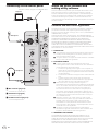
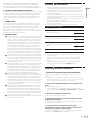
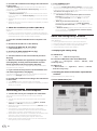
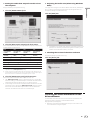
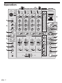
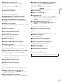
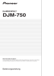
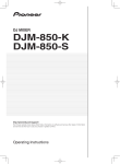
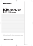
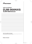
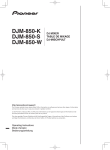
DJ MIXER
DJM-750
http://pioneerdj.com/support/
The Pioneer DJ support site shown above offers FAQs, information on software and various other types of
information and services to allow you to use your product in greater comfort.
Operating Instructions
Contents
How to read this manual
In this manual, names of channels and buttons indicated on the product, names of menus in the software, etc., are indicated within square
brackets ([ ]). (e.g. [MASTER] channel, [ON/OFF], [File] menu)
Before start
Features........................................................................................................ 3
Connections
Rear panel.................................................................................................... 4
Connecting input terminals........................................................................ 5
Connecting output terminals..................................................................... 5
Connecting to the control panel................................................................. 6
About the driver software and setting utility software.............................. 6
Operation
Basic Operation......................................................................................... 12
Advanced Operations................................................................................ 14
Types of effects
BOOST COLOR FX/SOUND COLOR FX effect types.............................. 16
Types of BEAT EFFECT............................................................................... 16
List of MIDI Messages
Changing the settings
About the auto standby function.............................................................. 21
About the talk over function..................................................................... 21
Setting preferences................................................................................... 21
Additional information
Troubleshooting......................................................................................... 22
Block Diagram........................................................................................... 24
About trademarks and registered trademarks....................................... 25
2
En
Before start
Before start
Features
This unit is a 4-channel DJ mixer carrying over the technology of the
Pioneer DJM series, the world standard for club sound. It is not only
equipped with a variety of functions for DJ performances, including
USB sound card, BOOST COLOR FX, SOUND COLOR FX and BEAT
EFFECT, it also uses a high sound quality, high reliability design and a
panel layout with high operability to provide powerful support for all DJ
performances.
24 bit/96 kHz STEREO 4-IN 4-OUT SOUND
CARD
This unit is equipped with a 24 bit/96 kHz stereo 4-in 4-out compatible
USB sound card.
This unit supports ASIO/Core Audio standards, so it can be used not
only for DJ performances with DJ software but also with a wide variety of
other software applications, including for software for creating music.
! Four sets of stereo sound from a single computer can be input to the
respective channels and mixed.
! Up to four sets of stereo sound can be output to the computer from
the respective channels (channels 1 to 4, REC OUT, crossfader sides
A and B and microphone).
! The sampling rate can be switched between 96 kHz, 48 kHz and
44.1 kHz.
BOOST COLOR FX/SOUND COLOR FX
The SOUND COLOR FX function that has been well received on the DJM
series is carried over and further evolved. By using the [BOOST] button
together with the four types of SOUND COLOR FX effects, new developments of the sound can be created easily. Furthermore, with the BOOST
COLOR FX function, changes can be applied to the effects by detecting
the speed at which the knob is turned, enabling even more dynamic
performances than before.
BEAT EFFECT
This unit also inherits the BEAT EFFECT feature popular on the DJM
series, equipped with 13 types of effects. The BOOST COLOR FX and
SOUND COLOR FX effects can be combined to create some 100 different
effects, letting the DJ produce a wide variety of sounds.
HIGH SOUND QUALITY
Measures have been taken for the digital/analog inputs/outputs to
improve and enhance sound quality. Thanks to sound processing with
a 96 kHz sampling, 24-bit high sound quality A/D converter and D/A
converter, the original is recreated sound faithfully, achieving powerful,
high-grade club sound.
BUILD QUALITY
This unit uses “P-LOCK Fader Cap” fader knobs equipped with lock
mechanisms.
STANDARD LAYOUT
This unit carries over the control panel layout of the Pioneer DJM series,
the world standard in DJ mixers.
The simple, straightforward layout of the control panel not only makes
for easy DJ performances, it also allows DJs using it for the first time to
operate it without hesitation.
En
3
Connections
Be sure to turn off the power and unplug the power cord from the power outlet whenever making or changing connections.
Refer to the operating instructions for the component to be connected.
Connect the power cord after all the connections between devices have been completed.
Be sure to use the included power cord.
Rear panel
1
2
3
For Europe
456
4
CH 4
OFF
ON
POWER
LINE
L
R
SEND
L (MONO)
f
CH 2
LINE
L
e
CH 1
CD/ LINE
L
MASTER2
L
Turns this unit’s power on and off.
2RETURN terminals (page 5)
Connect to the output terminal of an external effector. When the [L
(MONO)] channel only is connected, the [L (MONO)] channel input
is simultaneously input to the [R] channel.
3PHONO terminals (page 5)
Connect to a phono level (MM cartridge) output device. Do not input
line level signals.
To connect a device to the [PHONO] terminals, remove the shortcircuit pin plug inserted in the terminals.
Insert this short-circuit pin plug into the [PHONO] terminals when
nothing is connected to them to cut external noise.
4CD/LINE terminals (page 5)
Connect to a DJ player or a line level output component.
5SIGNAL GND terminal (page 5)
Connects an analog player’s ground wire here. This helps reduce
noise when the analog player is connected.
6LINE terminals (page 5)
Connect to a cassette deck or a line level output component.
7Kensington security slot
8CONTROL terminal (page 5)
This is a Ø 3.5 mm mini phone jack type DJ player control terminal.
If you connect a Pioneer DJ player using a control cable (supplied
with a DJ player), you can start playback of control other operations
of the DJ player with the fader of this unit.
PHONO CD/ LINE
L
R
R
DIGITAL
MASTER OUT
BOOTH
REC OUT
L
R
d
4
SIGNAL GND
R
MASTER1
R
1 GND
1POWER button (page 12)
En
CD/ LINE
R
AC IN
4
L
SIGNAL GND
R
For North America
45 3
CH 3
PHONO CD/ LINE
RETURN
L (MONO)
R
6
L
CONTROL
CH2
CH3
R
2 HOT
3 COLD
c
b
a
9
8
7
9DIGITAL MASTER OUT terminal (page 5)
Outputs the master channel audio signals.
aBOOTH terminals (page 5)
These are output terminals for a booth monitor.
bREC OUT terminals (page 5)
These are output terminals for recording.
cMASTER2 terminals (page 5)
Connect to a power amplifier, etc.
dMASTER1 terminals (page 5)
Connect to a power amplifier, etc.
Be sure to use these as balanced outputs. Be careful not to accidentally insert the power cord of another unit.
eSEND terminals (page 5)
Connect to the input terminal of an external effector. When the [L
(MONO)] channel only is connected, a monaural audio signal is
output.
fAC IN
Connects to a power outlet using the included power cord. Wait until
all connections between the equipment are completed before connecting the power cord.
Be sure to use the included power cord.
WARNING
The short-circuit pin plugs out of the reach of children and infants. If
accidentally swallowed, contact a doctor immediately.
Connecting input terminals
Analog player
Cassette deck, CD player, etc.
(line level output devices)
L R
L R
For Europe
L R
CH 4
OFF
ON
POWER
RETURN
L (MONO)
L R
CH 3
PHONO CD/ LINE
R
Analog player
LINE
L
L
CH 2
CD/ LINE
LINE
L
CH 1
CD/ LINE
SIGNAL GND
R
R
MASTER1
R
SEND
L (MONO)
R
To power outlet
R
DIGITAL
MASTER OUT
BOOTH
REC OUT
L
L
CONTROL
CH3
CH2
R
2 HOT
3 COLD
1 GND
L R
L
R
MASTER2
L
L
R
AC IN
PHONO CD/ LINE
SIGNAL GND
R
For North America
Connections
! When creating a DVS (Digital Vinyl System) combining a computer, audio interface, etc., be careful in connecting the audio interface to this unit’s
input terminals and in the settings of the input selector switches.
Also refer to the operating instructions of the DJ software and audio interface.
L R
L R
L R
Pioneer DJ players
Pioneer DJ players
! To use the fader start function, connect a control cable (page 12).
Connecting output terminals
For Europe
CH 4
CH 3
PHONO CD/ LINE
OFF
ON
POWER
RETURN
L (MONO)
R
LINE
L
R
AC IN
SEND
L (MONO)
LINE
L
CH 1
CD/ LINE
PHONO CD/ LINE
L
SIGNAL GND
R
MASTER1
R
L
R
MASTER2
L
R
R
DIGITAL
MASTER OUT
BOOTH
REC OUT
L
R
L
CONTROL
CH3
CH2
R
2 HOT
3 COLD
1 GND
L
R
Power amplifier 2 3 Power amplifier
External effector 1
CH 2
CD/ LINE
SIGNAL GND
R
For North America
L
L
R
Cassette deck, etc.
(analog input
recording device)
R
L
Power amplifier
(for booth monitor)
Digital audio
input device
1 Also connect the external effector to the [RETURN] terminal (input terminal).
2 Be sure to use the [MASTER1] terminals only for a balanced output. Connection with an unbalanced input (such as RCA) using an XLR to RCA
converter cable (or converter adapter), etc., may lower the sound quality and/or result in noise.
For connection with an unbalanced input (such as RCA), use the [MASTER2] terminals.
3 Be careful not to accidentally insert the power cord of another unit to [MASTER1] terminal.
En
5
Connecting to the control panel
Be sure to connect using the included USB cable.
About the driver software and
setting utility software
The driver software is required to input and output the sound of a computer using this unit’s built-in USB sound card. Prepare a computer
on which a Windows or Mac operating system is installed and the proprietary driver software provided by Pioneer. When the driver software
is installed, the settings utility software is installed at the same time.
Change the settings of the settings utility and the computer according to
your environment.
Computer
Software end user license agreement
MIC
Microphone
USB
CD/LINE
PHONO
USB
TRIM
OVER
1
2
10
9
7
MIC LEVEL
HI
4
1DEFINITIONS
2
1
0
0
-26 /
6
-1
HI
This Software End User License Agreement (“Agreement”) is between
you (both the individual installing the Program and any single legal
entity for which the individual is acting) (“You” or “Your”) and PIONEER
CORPORATION (“Pioneer”).
TAKING ANY STEP TO SET UP OR INSTALL THE PROGRAM MEANS
THAT YOU ACCEPT ALL OF THE TERMS OF THIS LICENSE AGREEMENT.
PERMISSION TO DOWNLOAD AND/OR USE THE PROGRAM IS
EXPRESSLY CONDITIONED ON YOUR FOLLOWING THESE TERMS.
WRITTEN OR ELECTRONIC APPROVAL IS NOT REQUIRED TO MAKE
THIS AGREEMENT VALID AND ENFORCEABLE. IF YOU DO NOT
AGREE TO ALL OF THE TERMS OF THIS AGREEMENT, YOU ARE NOT
AUTHORIZED TO USE THE PROGRAM AND MUST STOP INSTALLING IT
OR UNINSTALL IT, AS APPLICABLE.
MIXING
1 “Documentation” means written documentation, specifications
and help content made generally available by Pioneer to aid in
installing and using the Program.
2 “Program” means all or any part of Pioneer’s software licensed to
You by Pioneer under this Agreement.
2 PROGRAM LICENSE
CUE
MASTER
A
LEVEL
Headphones
0
PHONES
3
1MIC terminal (page 13)
Connects a microphone here.
2USB terminal (page 8)
Connect the computer.
3PHONES terminal (page 12)
Connect headphones here.
THRU
B
1 Limited License. Subject to this Agreement’s restrictions,
Pioneer grants to You a limited, non-exclusive, non-transferable,
license (without the right to sublicense):
a To install a single copy of the Program in Your computer or
mobile device, to use the Program only for Your personal purpose complying with this Agreement and the Documentation
(“Authorized Use”);
b To use the Documentation in support of Your Authorized Use;
and
c To make one copy of the Program solely for backup purposes, provided that all titles and trademark, copyright and
restricted rights notices are reproduced on the copy.
2 Restrictions. You will not copy or use the Program or
Documentation except as expressly permitted by this Agreement.
You will not transfer, sublicense, rent, lease or lend the Program,
or use it for third-party training, commercial time-sharing or
service bureau use. You will not Yourself or through any third
party modify, reverse engineer, disassemble or decompile the
Program, except to the extent expressly permitted by applicable
law, and then only after You have notified Pioneer in writing of
Your intended activities.
3 Ownership. Pioneer or its licensor retains all right, title and
interest in and to all patent, copyright, trademark, trade secret
and other intellectual property rights in the Program and
Documentation, and any derivative works thereof. You do not
acquire any other rights, express or implied, beyond the limited
license set forth in this Agreement.
4 No Support. Pioneer has no obligation to provide support,
maintenance, upgrades, modifications or new releases for the
Program or Documentation under this Agreement.
3 WARRANTY DISCLAIMER
THE PROGRAM AND DOCUMENTATION ARE PROVIDED “AS IS”
WITHOUT ANY REPRESENTATIONS OR WARRANTIES, AND YOU
AGREE TO USE THEM AT YOUR SOLE RISK. TO THE FULLEST EXTENT
PERMISSIBLE BY LAW, PIONEER EXPRESSLY DISCLAIMS ALL
WARRANTIES OF ANY KIND WITH RESPECT TO THE PROGRAM AND
DOCUMENTATION, WHETHER EXPRESS, IMPLIED, STATUTORY,
6
En
OR ARISING OUT OF COURSE OF PERFORMANCE, COURSE OF
DEALING OR USAGE OF TRADE, INCLUDING ANY WARRANTIES
OF MERCHANTABILITY, FITNESS FOR A PARTICULAR PURPOSE,
SATISFACTORY QUALITY, ACCURACY, TITLE OR NON-INFRINGEMENT.
You agree that any breach of this Agreement’s restrictions would cause
Pioneer irreparable harm for which money damages alone would be
inadequate. In addition to damages and any other remedies to which
Pioneer may be entitled, You agree that Pioneer may seek injunctive
relief to prevent the actual, threatened or continued breach of this
Agreement.
5TERMINATION
Pioneer may terminate this Agreement at any time upon Your breach
of any provision. If this Agreement is terminated, You will stop using
the Program, permanently delete it from your computer or mobile
device where it resides, and destroy all copies of the Program and
Documentation in Your possession, confirming to Pioneer in writing
that You have done so. Sections 2.2, 2.3, 2.4, 3, 4, 5 and 6 will continue in
effect after this Agreement’s termination.
! Before installing the driver software, turn off this unit’s power and
disconnect the USB cable connecting this unit to the computer.
! If you connect this unit to your computer without installing the driver
software first, an error may occur on your computer depending on
the system environment.
! If you have discontinued the installation process in progress, step
through the installation process again from the beginning according
to the following procedure.
!Read Software end user license agreement carefully before installing
this unit’s proprietary driver software.
! Before installing the driver software, terminate all other programs
running on your computer.
! The driver software is compatible with the following OSs.
Supported operating systems
1
Mac OS X 10.6 / 10.7 / 10.8
®
®
Windows 8/Windows 8 Pro
6 GENERAL TERMS
1 Limitation of Liability. In no event will Pioneer or its subsidiaries
be liable in connection with this Agreement or its subject matter,
under any theory of liability, for any indirect, incidental, special,
consequential or punitive damages, or damages for lost profits,
revenue, business, savings, data, use, or cost of substitute procurement, even if advised of the possibility of such damages or if
such damages are foreseeable. In no event will Pioneer’s liability
for all damages exceed the amounts actually paid by You to
Pioneer or its subsidiaries for the Program. The parties acknowledge that the liability limits and risk allocation in this Agreement
are reflected in the Program price and are essential elements of
the bargain between the parties, without which Pioneer would
not have provided the Program or entered into this Agreement.
2 The limitations or exclusions of warranties and liability contained
in this Agreement do not affect or prejudice Your statutory rights
as consumer and shall apply to You only to the extent such limitations or exclusions are permitted under the laws of the jurisdiction where You are located.
3 Severability and Waiver. If any provision of this Agreement is held
to be illegal, invalid or otherwise unenforceable, that provision
will be enforced to the extent possible or, if incapable of enforcement, deemed to be severed and deleted from this Agreement,
and the remainder will continue in full force and effect. The
waiver by either party of any default or breach of this Agreement
will not waive any other or subsequent default or breach.
4 No Assignment. You may not assign, sell, transfer, delegate or
otherwise dispose of this Agreement or any rights or obligations
under it, whether voluntarily or involuntarily, by operation of law
or otherwise, without Pioneer’s prior written consent. Any purported assignment, transfer or delegation by You will be null and
void. Subject to the foregoing, this Agreement will be binding
upon and will inure to the benefit of the parties and their respective successors and assigns.
5 Entire Agreement. This Agreement constitutes the entire agreement between the parties and supersedes all prior or contemporaneous agreements or representations, whether written or
oral, concerning its subject matter. This Agreement may not be
modified or amended without Pioneer’s prior and express written
consent, and no other act, document, usage or custom will be
deemed to amend or modify this Agreement.
6 You agree that this Agreement shall be governed and construed
by and under the laws of Japan.
Connections
4 DAMAGES AND REMEDIES FOR BREACH
Cautions on Installation
®
Windows 7 Home Premium/Professional/Ultimate
®
Windows Vista Home Basic/Home Premium/Business/
Ultimate
®
Windows XP Home Edition/Professional (SP3 or later)
32-bit
version
1
64-bit
version
1
32-bit
version
1
64-bit
version
1
32-bit
version
1
64-bit
version
1
32-bit
version
1
Windows® XP Professional x64 Edition is not supported.
! The included CD-ROM includes installation programs in the following 12 languages.
English, French, German, Italian, Dutch, Spanish, Portuguese,
Russian, Simplified Chinese, Traditional Chinese, Korean, and
Japanese
When using operating systems in other languages, follow the
instructions on the screen to select [English (English)].
Installing the driver software
About the installation procedure (Windows)
Read Cautions on Installation carefully before installing the driver
software.
! To install or uninstall the driver software, you need to be authorized
by the administrator of your computer. Log on as the administrator of
your computer before proceeding with the installation.
1 Insert the included CD-ROM into the computer’s CD
drive.
The CD-ROM folder appears.
! If the CD-ROM folder is not displayed after a CD-ROM is loaded,
open the CD drive from [Computer (or My Computer)] in the [Start]
menu.
2 Double-click [DJM-750_X.XXX.exe].
The driver installation screen appears.
3 When the language selection screen appears, select
[English] and click [OK].
You can select one from multiple languages depending on the system
environment of your computer.
4 Carefully read the Software end user license
agreement and if you consent to the provisions, put a
check mark in [I agree.] and click [OK].
If you do not consent to the provisions of the Software end user license
agreement, click [Cancel] and stop installation.
En
7
5 Proceed with installation according to the instructions
on the screen.
If [Windows Security] appears on the screen while the installation is
in progress, click [Install this driver software anyway] and continue
with the installation.
! When installing on Windows XP
If [Hardware Installation] appears on the screen while the installation is in progress, click [Continue Anyway] and continue with the
installation.
! When the installation program is completed, a completion message
appears.
! When the installation of the driver software is completed, you need to
reboot your computer.
About the installation procedure (Mac OS X)
Read Cautions on Installation carefully before installing the driver
software.
! To install or uninstall the driver software, you need to be authorized
by the administrator of your computer. Have the name and password
of the administrator of your computer ready in advance.
1 Insert the included CD-ROM into the computer’s CD
drive.
2 Double-click the CD icon on the desktop.
3 Double-click [DJM-750_M_X.X.X.dmg].
The [DJM-750AudioDriver] menu screen appears.
4 Double-click [DJM-750AudioDriver.pkg].
2 Press [POWER] button.
Turn on the power of this unit.
! The message [Installing device driver software] may appear when
this unit is first connected to the computer or when it is connected to
a different USB port on the computer. Wait a while until the message
[Your devices are ready for use] appears.
! When installing on Windows XP
—[Can Windows connect to Windows Update to search for
software?] may appear while the installation is in progress.
Select [No, not this time], then click [Next] to continue
installation.
—[What do you want the wizard to do?] may appear while
the installation is in progress. Select [Install the software
automatically (Recommended)], then click [Next] to continue
installation.
— If [Windows Security] appears on the screen while the installation is in progress, click [Install this driver software anyway]
and continue with the installation.
About the setting utility software
The setting utility can be used to make the checks and settings
described below.
— Checking the status of this unit’s input selector switches
— Setting the audio data output from this unit to the computer
— Adjusting the buffer size (when using Windows ASIO)
— Checking the version of the driver software
Displaying the setting utility
The driver installation screen appears.
5 Check the details on the screen and click [Continue
Anyway].
6 When the Software Use Agreement screen appears,
select [English], carefully read the Software end user
license agreement and click [Continue Anyway].
You can select one from multiple languages depending on the system
environment of your computer.
7 If you consent to the provisions of the Software end
user license agreement, click [Agree].
If you do not consent to the provisions of the Software end user license
agreement, click [Disagree] and stop installation.
8 Proceed with installation according to the instructions
on the screen.
! Click [Cancel] to cancel installation after it has started.
! When the installation of the driver software is completed, you need to
reboot your computer.
Connecting this unit and computer
1 Connect this unit to your computer via a USB cable.
This unit functions as an audio device conforming to the ASIO
standards.
! This operation does not work with computers that do not support
USB 2.0.
! When using ASIO-compatible applications, [USB 1/2], [USB 3/4],
[USB 5/6] and [USB 7/8] can be used as inputs.
! When using DirectX-compatible applications, only [USB 1/2] can be
used as the input.
! The computer’s recommended operating environment differs
according to the DJ software. Be sure to check the recommended
operating environment for the DJ software you are using.
! When another USB audio device is connected to the computer at the
same time, it may not operate or be recognized normally.
We recommend only connecting the computer and this unit.
! When connecting the computer and this unit, we recommend connecting directly to this unit’s USB port.
8
En
For Windows 8
Click [Start] menu > [DJM-750 Settings Utility].
For versions of Windows other than Windows 8
Click [Start] menu > [All Programs] > [Pioneer] > [DJM-750] > [DJM750 Settings Utility].
For Mac OS X
Click [Macintosh HD] icon > [Application] > [Pioneer] > [DJM-750]
> [DJM-750 Settings Utility].
Checking the status of this unit’s input selector
switches
Display the setting utility before starting.
Click the [MIXER INPUT] tab.
Adjusting the buffer size (when using Windows
ASIO)
Display the setting utility before starting.
If an application using this unit as the default audio device (DJ software,
etc.) is running, quit that application before adjusting the buffer size.
Display the setting utility before starting.
1 Click the [MIXER OUTPUT] tab.
Click the [ASIO] tab.
Connections
Setting the audio data output from this unit to
the computer
2 Click the [Mixer Audio Output] pull-down menu.
Select and set the audio data to be output to the computer from the flow
of audio signals inside this unit.
CH1
CH2
CH3
CH4
CH1 Timecode
PHONO1
CH2 Timecode
CD/LINE1
CH3 Timecode
CD/LINE1
CH4 Timecode
PHONO1
CH1 Timecode
CD/LINE1
CH2 Timecode
LINE1
CH3 Timecode
LINE1
CH4 Timecode
CD/LINE1
Post CH1 Fader2
Post CH2 Fader2
Post CH3 Fader2
Post CH4 Fader2
Cross Fader A2
Cross Fader A2
Cross Fader A2
Cross Fader A2
Cross Fader B2
Cross Fader B2
Cross Fader B2
Cross Fader B2
MIC
MIC
MIC
MIC
REC OUT2
REC OUT2
REC OUT2
None
None
None
REC OUT
None
2
! If the buffer size is made large, drops in audio data (breaks in the
sound) occur less easily, but the time lag due to the delay in the
transfer of the audio data (latency) increases.
Checking the version of the driver software
Display the setting utility before starting.
Click the [About] tab.
1 The audio data is output with the same volume at which it is input to this unit,
regardless of the [USB Output Level] setting.
2 When using for any purposes other than sound recording, pay attention to set
the DJ software so that sound loops are not generated. If sound loops are generated, sound with an unintended volume might be input or output.
3 Click the [USB Output Level] pull-down menu.
Adjust the volume of the audio data output from this unit.
! The [USB Output Level] setting is applied equally to all audio data.
However, when 1 on the table at step 2 is selected, the audio data is
output with the same volume at which it is input to this unit.
! If not enough volume can be achieved with the DJ software’s volume
adjustment alone, change the [USB Output Level] setting to adjust
the volume of the audio data output from this unit. Note that the
sound will be distorted if the volume is raised too high.
Checking the latest information on the
driver software
For the latest information on this unit’s exclusive driver software and
operating system compatibility, see the website below.
http://pioneerdj.com/support/
! Operation cannot be guaranteed when multiple units of this mixer
are connected to a single computer.
En
9
Operation
POWER
MIC
a
USB
CD/LINE
a
PHONO
USB 1/2
CD/LINE
a
LINE
USB 3/4
b
OVER
c
d
0
-1
HI
0
-2
2
12
EQ/
EQ
LOW
- 7 -26 /
12
TALK
ON OVER
OFF
- 7 -26 /
6
0
ISO
-7
6
LOW
-15
-15
-15
-24
-24
-24
-26 /
6
L
dB
-26 /
6
-26 /
6
dB
BOOST
NOISE
JET
e
MIDI
CRUSH
FILTER
SOUND COLOR FX
e
e
e
e
v
x
START
/ STOP
4
5
LOW
HEADPHONE CUE
HI
CUE
BALANCE
e
k
FADER START
CH-2
FLANGER PHASER
ROBOT
FILTER
VINYL BRAKE
CH-3
TRANS
HEAD PHONES
MONO SPLIT
f
STEREO
7
MIXING
10
10
10
9
9
9
8
8
8
7
7
7
6
6
L
f5
f5
4
4
4
3
3
3
2
2
2
1
1
1
0
0
0
f
SLIP ROLL
REVERB
ROLL
REV ROLL
SND/ RTN
SPIRAL
ECHO
DELAY
l
6
5
R
MONO STEREO
BOOTH MONITOR
4 MIC
3
y
CF.A
2
CF.B
1
MASTER
z
m
TIME
0
8
EQ CURVE
A
ISOLATOR EQ
CUE
MASTER
A
LEVEL
THRU
B
A
g
9
THRU
B
A
THRU
g
B
A
g
THRU
n
B
g
CH FADER
LEVEL / DEPTH
B
o
0
CROSS FADER ASSIGN
CROSS FADER
PHONES
MIN
MAX
ON / OFF
p
A
B
h
En
t
u
v
CUE
ON/ OFF
10
s
w
R
6
3
6
WAKE UP
-10
-15
-26 /
SETUP
TAP
-5
-24
dB
AUTO
/ TAP
-3
EQ/
-10
r
BEAT
-2
-15
dB
ms
-1
MID
-24
dB
%
0
6
- 7 -26 /
6
q
BPM
1
-26 /
-5
LOW
-10
4
MST
4
-3
ISO
- 7 -26 /
6
LOW
-10
EQ/
3
B
AUTO
TAP
7
-2
-5
2
A
PARAMETER
2
-1
MID
1
MIC
10
1
6
-3
ISO
c
d
2
-26 /
CH SELECT
0
OVER
HI
4
-2
EQ/
i
j
9
BEAT EFFECTS
LEVEL
7
HI
-1
MID
-5
LOW
-10
12
0
6
-3
ISO
-5
10
1
-26 /
-2
-3
12
c
d
2
-1
MID
9
4
1
6
b
7
2
-26 /
MASTER
USB 7/8
OVER
10
HI
4
1
0
c
d
7
2
1
9
PHONO
TRIM
OVER
10
HI
4
CD/LINE
TRIM
OVER
7
MIC LEVEL
USB 5/6
b
TRIM
9
LINE
CD/LINE
b
TRIM
10
a
C
1MIC LEVEL control (page 13)
Adjusts the sound level output from the [MIC] channel.
2EQ (HI, LOW) controls (page 13)
Adjusts the sound quality of the [MIC] channel.
3OFF, ON, TALK OVER selector switch (page 13)
4ON/OFF button (page 15)
Switches the MIDI function on and off.
5START/STOP button (page 15)
Sends the MIDI start/MIDI stop signals.
6FADER START (CH-2, CH-3) buttons (page 12)
These turn the fader start function on/off.
7MONO SPLIT, STEREO selector switch (page 12)
Switches how the monitor sound output from the headphones is
distributed.
8MIXING control (page 12)
This adjusts the monitor volume balance of the sound of channels for
which the [CUE] button is pressed and the sound of the [MASTER]
channel.
9LEVEL control (page 12)
Adjusts the sound level output from the headphones.
aInput selector switches (page 12)
Selects the input source of each channel from the components connected to this unit.
bChannel Level Indicator (page 12)
Displays the sound level of the respective channels before passing
through the channel faders.
cTRIM control (page 12)
Adjusts the level of audio signals input in each channel.
dEQ/ISO (HI, MID, LOW) controls (page 12)
These adjust the sound quality of the respective channels.
eCUE button (page 12)
Presses the [CUE] button(s) for the channel(s) you want to monitor.
fChannel Fader (page 12)
Adjusts the level of audio signals output in each channel.
gCROSS FADER ASSIGN (A, THRU, B) selector switch
(page 12)
Sets the output destination of each channel to [A] or [B].
hCrossfader (page 12)
Outputs audio signals assigned by the crossfader assign switch corresponding to the curve characteristics selected by [CROSS FADER]
(Crossfader Curve Selector Switch).
Switches the function of the [EQ/ISO (HI, MID, LOW)] controls.
oCH FADER (
,
) selector switch (page 12)
Switches the channel fader’s curve characteristics.
pCROSS FADER (
,
,
) selector switch (page 12)
This switches the crossfader curve characteristics.
Operation
Turns the microphone on/off.
nEQ CURVE (ISOLATOR, EQ) selector switch (page 12)
qMain unit display
rBEAT c, d buttons (page 15)
Set the beat fraction for synchronizing the effect sound.
sTAP (ENTER) button
— TAP: When the BPM measurement mode is set to [TAP], the
BPM is input manually by tapping the button with a finger (page
15).
— ENTER: Used to change this unit’s settings (page 21).
tSETUP (WAKE UP) button (page 21)
— SETUP: Displays the [USER SETUP] or [CLUB SETUP] screen.
— WAKE UP: Cancels the auto standby mode.
uAUTO/TAP button (page 14)
Switches the BPM measurement mode.
vCOLOR FX selector buttons (page 14)
These turn the SOUND COLOR FX and BOOST COLOR FX effects on
and off.
wBOOST button (page 14)
Switches the SOUND COLOR FX and BOOST COLOR FX functions.
xCOLOR control (page 14)
Adjusts the quantitative parameter of the SOUND COLOR FX and
BOOST COLOR FX effects.
yBeat effect selector switch (page 15)
Switches the BEAT EFFECT effect type.
zEffect channel selector switch (page 14)
Switches the channel to which the BEAT EFFECT and the SOUND
COLOR FX/BOOST COLOR FX effects are applied.
ATIME control (page 15)
Adjusts the BEAT EFFECT’s time parameter.
BLEVEL/DEPTH control (page 15)
Adjusts the BEAT EFFECT’s quantitative parameter.
CON/OFF button (page 15)
Turns the BEAT EFFECT function on/off.
Do not pull on the channel fader and crossfader knobs with excessive
force. The knobs have a structure by which they cannot be pulled off
easily. Pulling the knobs strongly may result in damaging the unit.
iMASTER LEVEL control (page 12)
Adjusts the audio level output from the [MASTER1] and [MASTER2]
terminals.
jMaster Level Indicator (page 12)
Displays the audio level output from the [MASTER1] and [MASTER2]
terminals.
kBALANCE control (page 13)
Adjusts the left/right balance of the sound output from the
[MASTER1] terminals, etc.
lMONO, STEREO selector switch (page 13)
Switches the sound output from the [MASTER1] terminals, etc.,
between monaural and stereo.
mBOOTH MONITOR control (page 13)
Adjusts the level of audio signals output from the [BOOTH] terminal.
En
11
Basic Operation
Outputting sound
1 Press [POWER] button.
Turn on the power of this unit.
2 Switch the input selector switches.
Selects the input sources for the different channels from among the
devices connected to this unit.
—[PHONO]: Selects the analog player connected to the [PHONO]
terminals.
—[CD/LINE], [LINE]: Selects the DJ player or cassette deck connected to the [CD/LINE] or [LINE] terminals.
—[USB */*]: Selects the sound of the computer connected to the
[USB] port.
3 Turn the [TRIM] control.
Adjusts the level of audio signals input in each channel.
The corresponding channel level indicator lights when audio signals are
being properly input to that channel.
4 Move the channel fader away from you.
Adjusts the level of audio signals output in each channel.
5 Switch the [CROSS FADER ASSIGN (A, THRU, B)]
selector switch.
Switches the output destination of each channel.
—[A]: Assigns to [A] (left) of the crossfader.
—[B]: Assigns to [B] (right) of the crossfader.
—[THRU]: Selects this when you do not want to use the crossfader.
(The signals do not pass through the crossfader.)
6 Set the crossfader.
This operation is not necessary when the [CROSS FADER ASSIGN (A,
THRU, B)] selector switch is set to [THRU].
7 Turn the [MASTER LEVEL] control.
Audio signals are output from the [MASTER1] and [MASTER2]
terminals.
The master level indicator lights.
Adjusting the sound quality
Turn the [EQ/ISO (HI, MID, LOW)] controls for the
respective channels.
The adjustable ranges for the respective controls are as shown below.
! HI: –26 dB to +6 dB (13 kHz)
! MID: –26 dB to +6 dB (1 kHz)
! LOW: –26 dB to +6 dB (70 Hz)
Switching the function of the [EQ/ISO (HI, MID,
LOW)] controls
Switch the [EQ CURVE (ISOLATOR, EQ)] selector switch.
—[ISOLATOR]: Functions as an isolator.
—[EQ]: The equalizer function is set.
Monitoring sound with headphones
1 Connect headphones to the [PHONES] terminal.
2 Press the [CUE] button(s) for the channel(s) you want
to monitor.
3 Switch the [MONO SPLIT, STEREO] selector switch.
—[MONO SPLIT]: The sound of the channels for which the [CUE]
button is pressed is output from the headphones output’s left
12
En
channel, the [MASTER] channel sound is output from the right
channel.
—[STEREO]: The sound of the channels for which the [CUE] button
is pressed is output from the headphones in stereo.
4 Turn the [MIXING] control.
This adjusts the monitor volume balance of the sound of channels for
which the [CUE] button is pressed and the sound of the [MASTER]
channel.
5 Turn the [LEVEL] control for [HEADPHONES].
The sound of the channels for which the [CUE] button is pressed is
output from the headphones.
! When the [CUE] button is pressed again, monitoring is canceled.
Switching the fader curve
Select the channel fader curve characteristics
Switch the [CH FADER (
,
)] selector switch.
—[ ]: The curve rises suddenly at the back side.
—[ ]: The curve rises gradually (the sound gradually increases as
the channel fader is moved away from the front side).
Select the crossfader curve characteristics
Switch the [CROSS FADER (
,
,
)] selector switch.
—[ ]: Makes a sharply increasing curve (if the crossfader is
moved away from the [A] side, audio signals are immediately
output from the [B] side).
—[ ]: Makes a curve shaped between the two curves above and
below.
—[ ]: Makes a gradually increasing curve (if the crossfader is
moved away from the [A] side, the sound on the [B] side gradually increases, while the sound on the [A] gradually decreases).
Starting playback on a DJ player using
the fader (fader start)
If you connect a Pioneer DJ player using a control cable (supplied with
a DJ player), you can start playback of control other operations of the DJ
player with the fader of this unit.
Connect this unit and Pioneer DJ player beforehand. For instructions on
connections, see Connecting input terminals on page 5.
Start playback using the channel fader
1 Set the [CROSS FADER ASSIGN (A, THRU, B)] selector
switch to [THRU].
2 Press one of the [FADER START (CH-2, CH-3)] buttons.
Select the channel to be started with the fader start function.
3 Set the channel fader to the nearest position towards
you.
4 Set the cue on the DJ player.
The DJ player pauses playback at the cue point.
5 Move the channel fader away from you.
Playback starts on the DJ player.
! If you set the channel fader back to the original position, the player
instantaneously returns to the cue point already set and pauses
playback (back cue).
Start playback using the crossfader
! To adjust the sound output from the [USB] terminals, select [REC
OUT] at [Mixer Audio Output] in the setting utility.
1 Set the [CROSS FADER ASSIGN (A, THRU, B)] selector
switch to [A] or [B].
1 Set the [MONO, STEREO] selector switch to [STEREO].
2 Press one of the [FADER START (CH-2, CH-3)] buttons.
The sound’s left/right balance changes according to the direction in
which the [BALANCE] control is turned and its position.
! Rotating to the rightmost position outputs only the right sound of
stereo audio. Rotating to the leftmost position outputs only the left
sound of stereo audio.
Select the channel to be started with the fader start function.
Set to the edge opposite the side on which the channel you want to use
with the fader start function is set.
4 Set the cue on the DJ player.
The DJ player pauses playback at the cue point.
5 Set the crossfader.
Playback starts on the DJ player.
! If you set the crossfader back to the original position, the player
instantaneously returns to the cue point already set and pauses
playback (back cue).
Operation
3 Set the crossfader.
2 Turn the [BALANCE] control.
Audio is output from the [BOOTH]
terminal
Turn the [BOOTH MONITOR] control.
Adjusts the level of audio signals output from the [BOOTH] terminal.
Using a microphone
1 Connect the microphone to the [MIC] jack.
2 Set the [OFF, ON, TALK OVER] selector switch to [ON]
or [TALK OVER].
—[ON]: The indicator lights.
—[TALK OVER]: The indicator flashes.
! When set to [TALK OVER], the sound of channels other than the
[MIC] channel is attenuated by 18 dB (default) when a sound of –10
dB or greater is input to the microphone.
! The [TALK OVER] sound attenuation level can be changed at
[USER SETUP] screen. For instructions on changing this, see
Changing the settings on page 21.
! The talk over mode can be switched to the normal mode or the
advanced mode. For instructions on changing it, see Changing the
settings on page 21.
3 Turn the [MIC LEVEL] control.
Adjust the level of the sound output from the [MIC] channel.
! Pay attention that rotating to the extreme right position outputs a
very loud sound.
4 Input audio signals to the microphone.
Adjusting the sound quality
Turn the [MIC] channels’ [EQ (HI, LOW)] controls.
The adjustable ranges for the respective controls are as shown below.
! HI: –12 dB to +12 dB (10 kHz)
! LOW: –12 dB to +12 dB (100 Hz)
Switching between monaural and stereo
audio
This switches the sound output from the [MASTER1], [MASTER2],
[BOOTH], [REC OUT], [PHONES], [DIGITAL MASTER OUT] and [USB]
terminals between monaural and stereo.
! To adjust the sound output from the [USB] terminals, select [REC
OUT] at [Mixer Audio Output] in the setting utility.
Switch the [MONO, STEREO] selector switch.
—[MONO]: Outputs monaural audio.
—[STEREO]: Outputs stereo audio.
Adjusting the L/R balance of audio
The left/right balance of the sound output from the [MASTER1],
[MASTER2], [BOOTH], [REC OUT], [PHONES], [DIGITAL MASTER OUT]
and [USB] terminals can be adjusted.
En
13
Advanced Operations
1
CH SELECT
2
1
2
3
4
MIC
A
B
MST
PARAMETER
3
AUTO
TAP
6
4
BPM
5
%
7
ms
8
Number
Name
Descriptions
SOUND BOOST
BEAT
COLOR COLOR
EFFECT
FX
FX
1
Effect display section
The name of the selected effect is displayed.
—
—
1
2
Channel select display section
The name of the channel to which the effect is applied is displayed.
1
1
1
3
AUTO (TAP)
[AUTO] lights when the BPM measurement mode is set to the auto mode.
[TAP] lights when in the manual input mode.
—
1
1
4
BPM value display (3 digits)
When in the auto mode, this displays the automatically detected BPM value.
When the BPM cannot be detected, the previously detected BPM value is displayed and
flashes.
When in the manual input mode, this displays the BPM value that was input manually.
—
1
1
5
BPM
This is always lit.
—
1
1
6
Parameter display section
This displays the parameters specified for the individual effects.
When the [BEAT c, d] button is pressed, the corresponding beat fraction is displayed
for 1 second.
When a value outside the parameter range is specified with the [BEAT c, d] button, the
value does not change and the display flashes.
—
—
1
7
% (ms)
These light according to the units for the different effects.
—
—
1
8
Beat display section
This lights according to the selected beat number position.
—
—
1
SOUND COLOR FX
BOOST COLOR FX
These are effects that change in association with the [COLOR] control.
Using the SOUND COLOR FX function
These are effects that change in association with the [BOOST] button,
the [COLOR] control and the tempo (BPM = Beats Per Minute) of the
currently playing track.
1 Press one of the [COLOR FX] selection buttons.
Using the BOOST COLOR FX function
This selects the type of effect.
The button that was pressed flashes.
! Even if one of the [COLOR FX] selection buttons is already selected,
when a different button is selected and pressed, that button is
selected.
! For the types of effects, see BOOST COLOR FX/SOUND COLOR FX
effect types on page 16.
2 Turn the effect channel selector switch.
This selects the channel to which the effect is applied.
—[1] – [4]: The effect is applied to the sound of the respective
channel.
—[MIC]: The effect is applied to the sound of [MIC] channel.
—[CF.A], [CF.B]: The effect is applied to the sound of the crossfader’s [A] (left) or [B] (right) side.
—[MASTER]: The effect is applied to the sound of the [MASTER]
channel.
! When the effect channel selector switch is turned while the [COLOR]
control is turned to any position other than the center and an effect
is being applied to the sound, the effect is canceled.
3 Turn the [COLOR] control.
When the control is turned, the effect is applied to the sound.
Canceling the SOUND COLOR FX effect
Press the [COLOR FX] selection button that is flashing.
The effect is canceled.
14
En
1 Press [AUTO/TAP] button.
Select the BPM measurement mode.
—[AUTO]: The BPM is measured automatically from the audio signal that is being input. The [AUTO] mode is set when this unit’s
power is turned on.
—[TAP]: The BPM is input manually by tapping the [TAP] button
with a finger.
! The [AUTO] BPM measurement range is BPM = 70 to 180. With
some tracks it may not be possible to measure the BPM correctly. If
the BPM cannot be measured, the BPM value on the display flashes.
In such cases, use the [TAP] button to input the BPM manually.
2 Press the [BOOST] button.
The [BOOST] button lights.
3 Press one of the [COLOR FX] selection buttons.
This selects the type of effect.
The button that was pressed flashes.
! Even if one of the [COLOR FX] selection buttons is already selected,
when a different button is selected and pressed, that button is
selected.
! For the types of effects, see BOOST COLOR FX/SOUND COLOR FX
effect types on page 16.
4 Turn the effect channel selector switch.
This selects the channel to which the effect is applied.
5 Turn the [COLOR] control.
When the control is turned, the effect is applied to the sound.
Changes can be applied to the effect by turning the control quickly.
Canceling the BOOST COLOR FX effect
! When the BPM is set using the [TAP] button, the beat fraction is set
to [1/1] and the time of one beat (quarter note) is set as the effect
time.
! The BPM can be set manually by turning the [TIME] control while
pressing the [TAP] button.
! The BPM can be set in units of 0.1 by pressing the [AUTO/TAP] button while pressing the [TAP] button and turning the [TIME] control
while pressing the two buttons.
Using the external effector
1 Connect this unit and external effector.
Operation
—[1] – [4]: The effect is applied to the sound of the respective
channel.
—[MIC]: The effect is applied to the sound of [MIC] channel.
—[CF.A], [CF.B]: The effect is applied to the sound of the crossfader’s [A] (left) or [B] (right) side.
—[MASTER]: The effect is applied to the sound of the [MASTER]
channel.
! When the effect channel selector switch is turned while the [COLOR]
control is turned to any position other than the center and an effect
is being applied to the sound, the effect is canceled.
For instructions on connections, see Connecting output terminals on
page 5.
2 Turn the beat effect selector switch.
Press the [COLOR FX] selection button that is flashing.
Select [SND/RTN].
The effect is canceled.
! When the [BOOST] button is pressed and turned off, the function
switches to SOUND COLOR FX.
3 Turn the effect channel selector switch.
This selects the channel to which the effect is applied.
4 Press the [ON/OFF] button for [BEAT EFFECTS].
BEAT EFFECT
This function lets you instantaneously set various effects according to
the tempo (BPM = Beats Per Minute) of the currently playing track.
Using the BEAT EFFECT function
1 Press [AUTO/TAP] button.
Select the BPM measurement mode.
—[AUTO]: The BPM is measured automatically from the audio signal that is being input. The [AUTO] mode is set when this unit’s
power is turned on.
—[TAP]: The BPM is input manually by tapping the [TAP] button
with a finger.
! The [AUTO] BPM measurement range is BPM = 70 to 180. With
some tracks it may not be possible to measure the BPM correctly. If
the BPM cannot be measured, the BPM value on the display flashes.
In such cases, use the [TAP] button to input the BPM manually.
The sound that has passed through the external effector is output from
the [MASTER] channel.
! When the [ON/OFF] button is pressed again, the effect turns off.
Operating DJ software using the MIDI
function
This selects the type of effect.
! For the types of effects, see Types of BEAT EFFECT on page 16.
! To use [SND/RTN], see Using the external effector below.
This unit is equipped with a “Full Assignable MIDI” function allowing the
operation information of virtually all of the unit’s controls and buttons
to be sent to the DJ software as MIDI signals. This unit can be used as a
USB MIDI controller when it is connected by USB cable to a computer
on which MIDI-compatible DJ software is installed. Furthermore, the
tempo (BPM) of the sound being played is sent as MIDI timing clocks, so
the tempo on the DJ software can be synchronized with the tempo of the
sound output from this unit.
To operate DJ software with this unit, first install the MIDI-compatible DJ
software on the computer. The MIDI-related settings must also be made
on the DJ software.
! For the messages output by this unit, see List of MIDI Messages on
page 19.
! If you want to change this unit’s MIDI channel, see Changing the
settings on page 21.
3 Turn the effect channel selector switch.
1 Connect this unit’s [USB] terminal to the computer.
2 Turn the beat effect selector switch.
This selects the channel to which the effect is applied.
—[1] – [4]: The effect is applied to the sound of the respective
channel.
—[MIC]: The effect is applied to the sound of [MIC] channel.
—[CF.A], [CF.B]: The effect is applied to the sound of the crossfader’s [A] (left) or [B] (right) side.
—[MASTER]: The effect is applied to the sound of the [MASTER]
channel.
4 Press the [BEAT c, d] button.
Set the beat fraction for synchronizing the effect sound.
The effect time corresponding to the beat fraction is set automatically.
5 Press the [ON/OFF] button for [BEAT EFFECTS].
The effect is applied to the sound.
The effect’s time parameter can be adjusted by turning the [TIME]
control.
The effect’s quantitative parameter can be adjusted by turning the
[LEVEL/DEPTH] control.
The [ON/OFF] button flashes when the effect is on.
! When the [ON/OFF] button is pressed again, the effect turns off.
Inputting the BPM manually
Tap the [TAP] button at least 2 times in rhythm with the
beat (in quarter notes) of the sound being played.
For details about connections, see Connecting to the control panel on
page 6.
2 Launch the DJ software.
3 Press the [MIDI] [ON/OFF] button.
Turn the MIDI function on.
Transmission of the MIDI messages begin.
! When a fader or control is moved, a message corresponding to the
position is sent.
! When the [START/STOP] button is pressed and held in for more than
2 seconds, a set of MIDI messages corresponding to the button,
fader or control positions is sent (Snapshot).
! When the [ON/OFF] button for [MIDI] is pressed again, transmission
of MIDI messages stops.
! The MIDI timing clocks (BPM information) are sent regardless of the
[MIDI] [ON/OFF] button’s setting.
Sending the MIDI start and MIDI stop messages
Press the [START/STOP] button for [MIDI].
! The MIDI start and MIDI stop messages are sent alternatively each
time the [START/STOP] button is pressed, regardless of whether the
MIDI function is on or off.
The average value of the interval at which the [TAP] button was tapped
by finger is set as the BPM.
En
15
Types of effects
BOOST COLOR FX/SOUND COLOR FX effect types
Effect Name
[BOOST] button status Descriptions
[COLOR] control
Off
White noise generated inside this unit is mixed in to the
sound of the channel via the filter and output.
! The volume can be adjusted by turning the [TRIM] controls for the respective channels. The sound quality can
be adjusted by turning the [EQ/ISO (HI, MID, LOW)]
controls.
Turn counterclockwise: The cut-off frequency of the filter
through which the white noise passes gradually decreases.
Turn clockwise: The cut-off frequency of the filter through
which the white noise passes gradually increases.
On
An echo is applied to the white noise.
The echo’s cycle changes according to the speed at which
the knob is turned.
An echo with a cycle equal to 3/4 the time of one beat of the
BPM is applied.
When turned quickly, and echo with a cycle of 1/4 is applied.
Off
The flanger effect is applied.
Turn counterclockwise: A flanger effect with a strong bass
sound is applied.
Turn clockwise: A flanger effect with a strong treble sound
is applied.
On
A reverberation effect similar to a tape echo is applied.
Turn counterclockwise: A reverberation effect is applied. The
further the control is turned, the longer the delay time.
Turn clockwise: A reverberation effect is applied. The further
the control is turned, the shorter the delay time.
The delay time changes according to the position of the
control.
When turned quickly, the speed at which the delay time
changes increases.
Off
Changes the original sound to a crushed-like sound for
output.
Turn counterclockwise: Increases the sound’s distortion.
Turn clockwise: The sound is crushed before passing through
the high pass filter.
On
An echo is applied to the [CRUSH] effect.
The echo’s cycle changes according to the speed at which
the knob is turned.
An echo with a cycle equal to 3/4 the time of one beat of the
BPM is applied.
When turned quickly, and echo with a cycle of 1/4 is applied.
Off
Outputs sound that has passed through a filter.
Turn counterclockwise: Gradually decreases the low-pass
filter’s cutoff frequency.
Turn clockwise: Gradually increases the high-pass filter’s
cutoff frequency.
On
An echo is applied to the [FILTER] effect.
The echo’s cycle changes according to the speed at which
the knob is turned.
An echo with a cycle equal to 3/4 the time of one beat of the
BPM is applied.
When turned quickly, and echo with a cycle of 1/4 is applied.
NOISE
JET
CRUSH
FILTER
Types of BEAT EFFECT
ECHO 1 2
A delay sound is output several times and gradually attenuated according to the beat fraction set with the [BEAT c, d] buttons.
With 1/1 beat echoes, the delay sounds are faded out according to the
track’s tempo even after the input sound has been cut.
DELAY 1
A delay sound is output once according to the beat fraction set with the
[BEAT c, d] buttons.
When 1/2 beat delay sound is added, 4 beats become 8 beats.
Original
(4 beats)
BEAT c, d buttons
(parameter 1)
Use these to set a time delay of 1/8 – 16/1 with
respect to the time of one beat of the BPM.
TIME control (parameter 2)
Use this to set the delay time.
1 to 4000 (ms)
LEVEL/DEPTH control
(parameter 3)
Use this to set the balance between the original
sound and the delay sound.
En
Fade-out
1 beat
1/2 delay
(8 beats)
16
Input sound turned off
Time
BEAT c, d buttons
(parameter 1)
Use these to set a time delay of 1/8 – 16/1 with
respect to the time of one beat of the BPM.
TIME control (parameter 2)
Use this to set the delay time.
1 to 4000 (ms)
LEVEL/DEPTH control
(parameter 3)
Use this to set the balance between the original
sound and the echo sound.
SPIRAL 1 2
FILTER 1
This function adds a reverberation effect to the input sound.
When the delay time is changed, the pitch changes simultaneously.
The filter’s cutoff frequency changes according to the beat fraction set
with the [BEAT c, d] buttons.
Input sound turned off
Fade-out
Use these to set a time delay of 1/8 – 16/1 with
respect to the time of one beat of the BPM.
TIME control (parameter 2)
Use this to set the delay time.
10 to 4000 (ms)
LEVEL/DEPTH control
(parameter 3)
Use this to set the balance between the original
sound and the effect sound and to set the quantitative parameter.
REVERB 1 2
This function adds a reverberation effect to the input sound.
Level
BEAT c, d buttons
(parameter 1)
Use these to set the cycle for moving the cut-off
frequency as a time of 1/4 – 64/1 with respect to the
time of one beat of the BPM.
TIME control (parameter 2)
Use this to set the cycle at which the cut-off frequency is moved.
10 to 32000 (ms)
LEVEL/DEPTH control
(parameter 3)
The further the control is turned clockwise, the more
the effect is stressed.
When turned all the way counterclockwise, only the
original sound is output.
Types of effects
BEAT c, d buttons
(parameter 1)
Direct sound
Frequency
Time
1 beat
FLANGER 1
A 1-cycle flanger effect is produced according to the beat fraction set
with the [BEAT c, d] buttons.
Early reflected sound
Reverberations
Short delay
1%
Time
Time
100%
BEAT c, d buttons
(parameter 1)
Use these to set the extent of the reverberation
effect, from 1 – 100 %.
TIME control (parameter 2)
Use this to set the degree of the reverb effect.
1 – 100 (%)
LEVEL/DEPTH control
(parameter 3)
Use this to set the balance between the original
sound and the effect sound and to set the cut-off
frequency of the filter through which the effect
sound passes.
Cycle
BEAT c, d buttons
(parameter 1)
Use these to set the 1/4 – 64/1 effect time with
respect to the time of one beat of the BPM.
TIME control (parameter 2)
Use this to set the cycle by which the flanger effect
moves.
10 to 32000 (ms)
LEVEL/DEPTH control
(parameter 3)
The further the control is turned clockwise, the more
the effect is stressed.
When turned all the way counterclockwise, only the
original sound is output.
PHASER 1
The phaser effect changes according to the beat fraction set with the
[BEAT c, d] buttons.
TRANS 1
The sound is cut according to the beat fraction set with the [BEAT c, d]
buttons.
Cut
Phase shift
Cut
Time
Cycle
1/1 beat
Time
BEAT c, d buttons
(parameter 1)
Use these to set a cut time of 1/16 – 16/1 with
respect to the time of one beat of the BPM.
TIME control (parameter 2)
Use this to set the effect time.
10 to 16000 (ms)
LEVEL/DEPTH control
(parameter 3)
Sets the balance between the original sound and the
effect sound.
BEAT c, d buttons
(parameter 1)
Use these to set the cycle for moving the phaser
effect as of time of 1/4 – 64/1 with respect to the
time of one beat of the BPM.
TIME control (parameter 2)
This sets the cycle by which the phaser effect is
moved.
10 to 32000 (ms)
LEVEL/DEPTH control
(parameter 3)
The further the control is turned clockwise, the more
the effect is stressed.
When turned all the way counterclockwise, only the
original sound is output.
ROBOT 1
The original sound is changed to a sound like one produced by a robot.
BEAT c, d buttons
(parameter 1)
Use these to set the degree of the effect sound, from
-100 – 100 %.
TIME control (parameter 2)
Use this to set the degree of the effect sound.
-100–100 (%)
LEVEL/DEPTH control
(parameter 3)
Sets the balance between the original sound and the
effect sound.
En
17
VINYL BRAKE 1 2
REV ROLL 1 2
The playing speed of the input sound changes according to the beat
multiple set with the [BEAT c, d] buttons.
The sound being input at the point when the [ON/OFF] button is pressed
is recorded, and the recorded sound is reversed then output repeatedly
according to the beat fraction set with the [BEAT c, d] buttons.
Playing speed
Original
Single speed
Stop
Time
Cycle
BEAT c, d buttons
(parameter 1)
Sets the cycle at which the playing speed of the input
sound changes to 1/4 – 64/1 with respect to the time
of one beat of the BPM.
TIME control (parameter 2)
Sets the cycle at which the playing speed of the input
sound changes.
10 to 32000 (ms)
LEVEL/DEPTH control
(parameter 3)
Sets the balance between the original sound and the
effect sound, as well as the amount of change in the
playing speed.
Effect turned on
1/1 reverse
roll
Reversed and repeated
BEAT c, d buttons
(parameter 1)
Use these to set an effect time of 1/16 – 16/1 with
respect to the time of one beat of the BPM.
TIME control (parameter 2)
Use this to set the effect time.
10 to 4000 (ms)
LEVEL/DEPTH control
(parameter 3)
Use this to set the balance between the original
sound and the ROLL sound as well as the length of
the ROLL that is played.
SLIP ROLL 1 2
The sound being input at the point when the [ON/OFF] is pressed is
recorded, and the recorded sound is output repeatedly according to the
beat fraction set with the [BEAT c, d] buttons.
When the effect time changes, the input sound is recorded again.
SND/RTN 1
Connect an external effector, etc., here.
SEND
Original
RETURN
Effect turned on
Changed from 1/2
to 1/1
POWER
MIC
USB
CD/LINE
PHONO
USB 1/2
CD/LINE
TRIM
LINE
USB 3/4
LINE
CD/LINE
TRIM
OVER
USB 5/6
CD/LINE
TRIM
OVER
PHONO
MASTER
BEAT EFFECTS
LEVEL
USB 7/8
TRIM
OVER
CH SELECT
0
OVER
1
MIC
OVER
2
3
A
B
4
MST
PARAMETER
10
10
9
7
1
0
0
0
6
LOW
- 7 -26 /
- 7 -26 /
6
- 7 -26 /
SETUP
TAP
-7
6
Effector
WAKE UP
-10
LOW
BOOST
NOISE
-15
-15
JET
-24
L
-26 /
6
AUTO
/ TAP
-5
-24
dB
-26 /
6
BEAT
-2
-3
ISO
-10
-24
dB
-26 /
6
6
-15
-24
dB
-26 /
-1
EQ/
-5
LOW
-10
-15
-24
dB
%
0
6
MID
-2
-3
ISO
ms
1
-26 /
-1
EQ/
- 7 -26 /
6
LOW
-10
-15
12
TALK
ON OVER
0
6
MID
-5
BPM
2
1
-26 /
-2
-3
ISO
-5
LOW
-10
12
OFF
0
-1
EQ/
-3
ISO
4
2
1
6
MID
-2
EQ/
-5
EQ
-26 /
-1
MID
-2
-3
12
AUTO
TAP
7
HI
4
2
1
-26 /
-1
HI
12
9
7
HI
4
2
10
10
9
7
HI
4
2
Roll
10
9
7
HI
4
MIC LEVEL
dB
R
6
CRUSH
FILTER
SOUND COLOR FX
CUE
MIDI
1/2 repeat
1/1 repeat
START
/ STOP
ON/ OFF
CH-2
FLANGER PHASER
ROBOT
FILTER
VINYL BRAKE
TRANS
CH-3
10
10
10
9
9
9
8
8
8
7
HEAD PHONES
7
6
TIME control (parameter 2)
Use this to set the effect time.
10 to 4000 (ms)
LEVEL/DEPTH control
(parameter 3)
Use this to set the balance between the original
sound and the ROLL sound as well as the length of
the ROLL that is played.
ROLL 1 2
The sound being input at the point when the [ON/OFF] is pressed is
recorded, and the recorded sound is output repeatedly according to the
beat fraction set with the [BEAT c, d] buttons.
Original
Effect turned on
1/1 roll
Repeated
18
BEAT c, d buttons
(parameter 1)
Use these to set an effect time of 1/16 – 16/1 with
respect to the time of one beat of the BPM.
TIME control (parameter 2)
Use this to set the effect time.
10 to 4000 (ms)
LEVEL/DEPTH control
(parameter 3)
Use this to set the balance between the original
sound and the ROLL sound as well as the length of
the ROLL that is played.
En
4 MIC
3
2
CF.A
CF.B
1
2
1
0
DELAY
3
2
1
ROLL
REV ROLL
SND/ RTN
SPIRAL
ECHO
BOOTH MONITOR
4
3
2
SLIP ROLL
REVERB
5
4
3
R
6
5
4
L
MONO STEREO
7
6
5
STEREO
MIXING
Use these to set an effect time of 1/16 – 16/1 with
respect to the time of one beat of the BPM.
HI
CUE
BALANCE
FADER START
MONO SPLIT
BEAT c, d buttons
(parameter 1)
LOW
HEADPHONE CUE
MASTER
1
0
0
TIME
0
EQ CURVE
ISOLATOR EQ
CUE
MASTER
A
LEVEL
THRU
B
A
THRU
B
A
THRU
B
A
THRU
B
CH FADER
LEVEL / DEPTH
0
CROSS FADER ASSIGN
CROSS FADER
MIN
MAX
ON / OFF
PHONES
A
B
DJM-750
BEAT c, d buttons
(parameter 1)
—
TIME control (parameter 2)
—
LEVEL/DEPTH control
(parameter 3)
This adjusts the sound level input to the [RETURN]
terminal.
1 When [CF.A], [CF.B] or [MASTER] is selected with the effect channel
selector switch, if the sound of the channel you want to monitor is
not being output to the [MASTER] channel, the effect sound cannot be monitored even if the [CUE] button for [BEAT EFFECTS] is
pressed.
2 If the effect is off, the effect sound cannot be monitored even by
pressing the [CUE] button for [BEAT EFFECTS].
List of MIDI Messages
! “CC” is the abbreviation of “control change”. A control change is a type of MIDI signal used to transmit various types of control information, such as
timbre, volume, etc.
On this unit, values from 0 to 127 are output as CC mainly when controls and faders are operated. CC are also output when certain buttons are
operated.
! “Note” is a MIDI term used when pressing or releasing notes on a piano or other keyboard.
Category
CH2
CH3
CH4
Crossfader
Master
BOOTH MONITOR
BEAT EFFECTS
MIDI assignment
Trigger/Toggle
Transmitted data
CC 001
—
0-127
HI
Control
CC 002
—
0-127
MID
Control
CC 003
—
0-127
LOW
Control
CC 004
—
0-127
CUE
Button
CC 070
Trigger/Toggle
OFF=0, ON=127
Channel fader
Control
CC 017
—
0-127
CROSS FADER
ASSIGN
Switch
CC 065
—
0, 64, 127
TRIM
Control
CC 006
—
0-127
HI
Control
CC 007
—
0-127
MID
Control
CC 008
—
0-127
LOW
Control
CC 009
—
0-127
CUE
Button
CC 071
Trigger/Toggle
OFF=0, ON=127
Channel fader
Control
CC 018
—
0-127
CROSS FADER
ASSIGN
Switch
CC 066
—
0, 64, 127
TRIM
Control
CC 012
—
0-127
HI
Control
CC 014
—
0-127
MID
Control
CC 015
—
0-127
LOW
Control
CC 021
—
0-127
CUE
Button
CC 072
Trigger/Toggle
OFF=0, ON=127
Channel fader
Control
CC 019
—
0-127
CROSS FADER
ASSIGN
Switch
CC 067
—
0, 64, 127
TRIM
Control
CC 080
—
0-127
HI
Control
CC 081
—
0-127
MID
Control
CC 092
—
0-127
LOW
Control
CC 082
—
0-127
CUE
Button
CC 073
Trigger/Toggle
OFF=0, ON=127
Channel fader
Control
CC 020
—
0-127
CROSS FADER
ASSIGN
Switch
CC 068
—
0, 64, 127
Crossfader
CH FADER (
Fader curve
SW Type
Control
,
CROSS FADER (
,
)
)
,
Control
CC 011
—
0-127
Switch
CC 094
—
0, 127
Switch
CC 095
—
0, 64, 127
MASTER LEVEL
Control
CC 024
—
0-127
BALANCE
Control
CC 023
—
0-127
CUE
Button
CC 074
Trigger/Toggle
OFF=0, ON=127
EQ CURVE
(ISOLATOR, EQ)
Switch
CC 033
—
0, 127
BOOTH MONITOR
Control
CC 025
—
0-127
c
Button
CC 076
Trigger only
OFF=0, ON=127
d
Button
CC 077
Trigger only
OFF=0, ON=127
AUTO/TAP
Button
CC 069
Trigger/Toggle
OFF=0, ON=127
TAP
Button
CC 078
Trigger only
OFF=0, ON=127
CUE
Button
CC 075
Trigger/Toggle
OFF=0, ON=127
List of MIDI Messages
CH1
SW Name
TRIM
En
19
Category
SW Name
EFFECT
SELECT
BEAT EFFECTS
MIC
Fader Start
HEADPHONES
Fader Start
1
2
!
20
Trigger/Toggle
Transmitted data
CC 042
2
OFF=0, ON=127
ECHO
Switch
CC 055
2
OFF=0, ON=127
SPIRAL
Switch
CC 043
2
OFF=0, ON=127
REVERB
Switch
CC 054
2
OFF=0, ON=127
TRANS
Switch
CC 053
2
OFF=0, ON=127
FILTER
Switch
CC 059
2
OFF=0, ON=127
FLANGER Switch
CC 050
2
OFF=0, ON=127
PHASER
Switch
CC 057
2
OFF=0, ON=127
ROBOT
Switch
CC 051
2
OFF=0, ON=127
VINYL
BRAKE
Switch
CC 061
2
OFF=0, ON=127
SLIP
ROLL
Switch
CC 058
2
OFF=0, ON=127
ROLL
Switch
CC 046
2
OFF=0, ON=127
REV
ROLL
Switch
CC 047
2
OFF=0, ON=127
SND/RTN Switch
CC 062
2
OFF=0, ON=127
CH1
Switch
CC 034
2
OFF=0, ON=127
CH2
Switch
CC 035
2
OFF=0, ON=127
CH3
Switch
CC 036
2
OFF=0, ON=127
CH4
Switch
CC 037
2
OFF=0, ON=127
MIC
Switch
CC 038
2
OFF=0, ON=127
CF.A
Switch
CC 039
2
OFF=0, ON=127
CF.B
Switch
CC 040
2
OFF=0, ON=127
MASTER
Switch
CC 041
2
OFF=0, ON=127
Switch
CC 013
—
—
Switch
CC 045
—
TIME value (When FLANGER,
PHASER, FILTER or VINYL BRAKE
is selected, the value is halved.
When a negative value is selected,
it is set to a positive value.)
LEVEL/DEPTH
Switch
CC 091
—
0-127
ON/OFF
! When an effect
other than [SND/
RTN] is selected
at BEAT EFFECT
Button
CC 114
—
OFF=0, ON=127
ON/OFF
! When [SND/
RTN] is selected
at BEAT EFFECT
Button
CC 064
—
OFF=0, ON=127
NOISE
Button
CC 085
Trigger/Toggle1
OFF=0, ON=127
JET
Button
CC 084
Trigger/Toggle1
OFF=0, ON=127
CRUSH
Button
CC 086
Trigger/Toggle1
OFF=0, ON=127
FILTER
Button
CC 087
Trigger/Toggle1
OFF=0, ON=127
BOOST
Button
CC 100
Trigger/Toggle
OFF=0, ON=127
EFFECT KNOB
Control
CC 005
—
0-127
HI
Control
CC 030
—
0-127
LOW
Control
CC 031
—
0-127
FADER START CH-2
Button
CC 089
Trigger/Toggle
OFF=0, ON=127
FADER START CH-3
Button
CC 090
Trigger/Toggle
OFF=0, ON=127
MIXING
Control
CC 027
—
0-127
LEVEL
Control
CC 026
—
0-127
Timing Clock
—
Timing Clock
—
—
Note 103
—
BACK CUE = 0, PLAY = 127
EFFECT
SELECT
FADER START CH-2
Note 104
—
BACK CUE = 0, PLAY = 127
START
Button
START
—
—
STOP
Button
STOP
—
—
FADER START CH-3
MIDI
MIDI assignment
Switch
TIME
SOUND COLOR FX
(BOOST COLOR FX)
SW Type
DELAY
When turning one button on switches another button from on to off, MIDI on and off messages are sent from the two buttons.
When there is no button that switches off, only the MIDI on message is sent from the button that was pressed.
When switched from one position to another position, the MIDI ON and OFF signals are sent respectively from both positions.
When the [START/STOP] button is pressed for over 1 second, MIDI messages corresponding to the positions of the buttons, faders and controls are sent in a bundle
(Snapshot).
The MIDI Snapshot sends all MIDI messages other than MIDI start and MIDI stop.
En
Changing the settings
1 Press the [SETUP (WAKE UP)] button for over 1
second.
About the auto standby function
The [USER SETUP] screen is displayed.
! To display the [CLUB SETUP] screen, first turn this unit’s power
off, then press the [POWER] button while pressing the [SETUP
(WAKE UP)] button.
2 Press the [BEAT c, d] button.
Select the setting item.
3 Press the [TAP] button.
The screen switches to the setting item’s setting value change screen.
When [Auto Standby] is set to [ON], the standby mode is set automatically if 4 hours pass with all of the conditions shown below met.
— That none of this unit’s buttons or controls are operated.
— That no audio signals of –10 dB or greater are input to this unit’s
input terminals.
! When the [SETUP (WAKE UP)] button is pressed, the standby mode
is canceled.
! This unit is shipped with the auto standby function turned on. If you
do not want to use the auto standby function, set [Auto Standby] to
[OFF].
Change the setting value.
About the talk over function
5 Press the [TAP] button.
Enter the setting value.
The previous screen reappears.
! To return to the previous screen without changing the settings, press
the [AUTO/TAP] button.
The talk over function has the two modes described below.
—[ADV] (advanced talk over): The mid-range only of the sound of channels other than the [MIC] channel is attenuated according to the
[Talk Over LEVEL] setting value and output.
dB
6 Press the [SETUP (WAKE UP)] button.
Close the [USER SETUP] screen.
! To close the [CLUB SETUP] screen, press the [POWER] button to turn
this unit’s power off.
Changing the settings
4 Press the [BEAT c, d] button.
Frequency
—[NOR] (normal talk over): The sound of channels other than the [MIC]
channel is attenuated according to the [Talk Over LEVEL] setting
value and output.
dB
Frequency
Setting preferences
*: Setting upon purchase
Mode
USER SETUP
CLUB SETUP
Options settings
Screen display
Setting value
Descriptions
MIDI CH
MIDI CH
1* to 16
Sets the MIDI channel.
MIDI Button Type
MIDI BT
TGL*, TRG
Selects the MIDI signal transmission mode, [TGL (TOGGLE)] or [TRG
(TRIGGER)].
Talk Over Mode
TLK MOD
ADV*, NOR
Selects the talk over function’s mode, [ADV(ADVANCED)] or
[NOR(NORMAL)].
Talk Over LEVEL
TLK LVL
–6 dB, –12 dB,
–18 dB*, –24 dB
Sets the talk over function’s sound attenuation level.
Digital Master Out
Level
DOUT LV
–19 dB*, –15 dB,
–10 dB, –5 dB
Sets the maximum level of the sound output from the [DIGITAL MASTER
1
OUT] terminals.
Digital Master Out
Sampling Rate
DOUT FS
48 kHz, 96 kHz*
Sets the digital signal’s sampling rate.
Sets the attenuation level of the sound output from the [MASTER1] and
[MASTER2] terminals.
MASTER ATT.
MST ATT
–6 dB, –3 dB, 0 dB*
Auto Standby
AUTOSTB
ON*, OFF
Turns the auto standby function on and off.
Sets whether or not to output the microphone’s audio signals from [BOOTH]
terminals.
Mic Output To Booth
Monitor
MIC BTH
ON*, OFF
Peak Limiter
PKLIMIT
ON*, OFF
Lessens sudden, unpleasant digital clipping of the master output.
PC UTILITY
PC UTLY
ON*, OFF
Sets whether or not to launch the computer’s setting utility software automatically when a USB cable is connected.
Factory Reset
INITIAL
YES, NO*
Restores all the settings to their factory defaults.
1 Note that the output sound may be distorted even if the master level indicator does not light up to the very top.
En
21
Additional information
Troubleshooting
! Incorrect operation is often mistaken for trouble or malfunction. If you think that there is something wrong with this component, check the points
below. Sometimes the trouble may lie in another component. Inspect the other components and electrical appliances being used. If the trouble
cannot be rectified after checking the items below, ask your nearest Pioneer authorized service center or your dealer to carry out repair work.
! The player may not operate properly due to static electricity or other external influences. In such cases, normal operation may be restored by
unplugging the power cord then plugging it back in.
Problem
Check
Remedy
The power is not turned on.
Is the power cord properly connected?
Plug in the power cord to an AC outlet.
No sound or small sound.
Is the input selector switch set to the proper
position?
Switch the input selector switch to switch the channel’s input source. (page 12)
Are the connection cables properly connected?
Connect the connection cables properly. (page 5)
Are the terminals and plugs dirty?
Clean the terminals and plugs before making connections.
Is [MASTER ATT.] set to [–6 dB], etc.?
At the [CLUB SETUP] screen, switch [MASTER ATT.]. (page 21)
Digital sound cannot be output.
Is the digital audio output’s sampling frequency
(fs) suited for the specifications of the connected
device?
On the [CLUB SETUP] screen, set [Digital Master Out Sampling Rate] according to the specifications of the connected equipment. (page 21)
Distorted sound.
Is the sound level output from the [MASTER]
channel appropriately set?
Adjust the [MASTER LEVEL] control so that the master channel level indicator
lights at around [0 dB] at the peak level. (Page 12)
Set [MASTER ATT.] to [–3 dB] or [–6 dB]. (page 21)
Is the level of audio input to each channel properly
set?
Adjust the [TRIM] control so that the channel level indicator lights at about
[0 dB] at the peak level. (Page 12)
Can’t crossfade.
Are the CROSS FADER ASSIGN (A, THRU, B)
selector switches properly set?
Set the [CROSS FADER ASSIGN (A, THRU, B)] selector switches for the different
channels properly. (Page 12)
Can’t fader start a DJ player.
Is the [FADER START (CH-2, CH-3)] button set
to [OFF]?
Set the [FADER START (CH-2, CH-3)] button on the control panel to [ON]. (Page
12)
Is the DJ player properly connected to the
[CONTROL] terminal?
Properly connect the DJ player to the [CONTROL] terminal using the control
cord. (page 5)
Are the audio cables properly connected?
Connect this unit’s audio input terminals and the DJ player’s audio output
terminals by audio cable. (page 5)
[BEAT EFFECTS] does not work.
Is the effect channel selector switch set to the
proper position?
Turn the effect channel selector switch to select the channel to which you want
to apply the effect. (Page 15)
[SOUND COLOR FX] does not work.
Is the effect channel selector switch set to the
proper position?
Turn the effect channel selector switch to select the channel to which you want
to apply the effect. (Page 15)
Is the [COLOR] control set to an appropriate
position?
Turn the [COLOR] control clockwise or counterclockwise. (page 14)
Is the effect channel selector switch set to the
proper position?
Turn the effect channel selector switch to select the channel to which you want
to apply the effect. (Page 15)
Is the [COLOR] control set to an appropriate
position?
Turn the [COLOR] control clockwise or counterclockwise. (page 14)
Is the [SOUND COLOR FX] [BOOST] button set
to [ON]?
Set the [SOUND COLOR FX] [BOOST] button to [ON]. (page 14)
Is the [ON/OFF] button for [BEAT EFFECTS] set
to [ON]?
Press the [ON/OFF] button for [BEAT EFFECTS] to set [SND/RTN] to [ON]. (page
15)
Is the external effector properly connected to the
[SEND] or [RETURN] terminal?
Connect the external effector to the [SEND] and [RETURN] terminals. (page 5)
Is the external effector’s audio output level set to
an appropriate level?
Adjust the external effector’s audio output level.
[BOOST COLOR FX] does not work.
Can’t use an external effector.
Distorted sound from an external
effector.
Tempo (BPM) cannot be measured or Is the audio input level too high or too low?
measurement value of tempo (BPM) is
implausible.
Measured tempo (BPM) differs from
tempo indicated on CD.
—
MIDI sequencer does not synchronize. Is the MIDI sequencer’s sync mode set to Slave?
Does the MIDI sequencer you are using support
MIDI timing clocks?
MIDI control does not work.
This unit is not recognized after it has
been connected to a computer.
22
En
Adjust the [TRIM] control so that the channel level indicator lights at about
[0 dB] at the peak level. (Page 12)
For some tracks, it may not be possible to measure the tempo (BPM). Use the
[TAP] button to input the tempo manually. (page 15)
The values may differ slightly due to the different ways in which the BPM is
measured.
Set the MIDI sequencer’s sync mode to Slave.
MIDI sequencers not supporting MIDI timing clocks cannot be synchronized.
Is the MIDI channel turned on?
Press the [ON/OFF] button for [MIDI]. (page 15)
Are the MIDI settings properly set?
To operate DJ software with this unit, this unit’s MIDI messages must be
assigned to the DJ software you are using. For instructions on assigning messages, see your DJ software’s operating instructions.
Is the driver software properly installed on your
computer?
Install the driver software. If it is already installed, reinstall it. (page 6)
Problem
Check
Remedy
Sound of a computer cannot be
output from this unit.
Are this unit and computer properly connected?
Connect this unit and the computer directly using the included USB cable. (page
6)
Are the audio output device settings properly set?
Select this unit with the audio output device settings. For instructions on making
settings for your application, see your application’s operating instructions.
Is the input selector switch set to the proper
position?
Set the input selector switch to the [USB */*] position. (Page 12)
Effect sound cannot be monitored
even when the [CUE] button for [BEAT
EFFECTS] is pressed.
—
For [ECHO], [SPIRAL], [REVERB], [ROLL], [SLIP ROLL], [REV ROLL] and
[VINYL BRAKE], when the effect is off, the effect sound cannot be monitored.
This is not a malfunction.
Sound is distorted when an analog
player is connected to this unit’s
[PHONO] terminals.
Or, lighting of the channel level
indicator does not change even when
the [TRIM] control is turned.
Have you connected an analog player with a builtin phono equalizer?
For analog players with built-in phono equalizers, connect the player to the [CD/
LINE] or [LINE] terminals. (page 5)
If the analog player with built-in phono equalizer has a PHONO/LINE selector
switch, switch it to PHONO.
Is an audio interface for computers connected
between the analog player and this unit?
If the audio interface for computers has a line level output, connect it to the [CD/
LINE] or [LINE] terminal. (page 5)
If the analog player has a PHONO/LINE selector switch, switch it to PHONO.
Additional information
En
23
Block Diagram
MIC
MIC LEVEL
ADC
DIGITAL
MASTER
CH1
CD/LINE
FPGA
DIT
ADC
PHONO
MUTE
PHONES
MUTE
MASTER 1
DAC
Digital MASTER
MIC
CH1_ASEL_OUT
CH2
CD/LINE
CH1_Analog
PHONES
CH2_Analog
MASTER
CH3_Analog
BOOTH
ADC
LINE
MUTE
CH2_ASEL_OUT
DAC
CH3
CD/LINE
ADC
LINE
D SP
CH4_Analog
REC
CH3_ASEL_OUT
CH4
CD/LINE
SEND
RETURN
MASTER 2
MUTE
BOOTH
MUTE
REC
MUTE
SEND
DAC
ADC
PHONO
MUTE
CH1_USB1/2
USB1/2
CH2_USB3/4
USB3/4
CH3_USB5/6
USB5/6
CH4_USB7/8
USB7/8
CH4_ASEL_OUT
RETURN
ADC
USB
CH1 USB1/2 IN
USB
Type B
CH2 USB3/4 IN
I/Fμ com
USB
CH3 USB5/6 IN
CH4 USB7/8 IN
CH1 USB1/2 OUT
CH2 USB3/4 OUT
CH3 USB5/6 OUT
CH4 USB7/8 OUT
Booth
Level
CHx in
Phono
AMP
CH1,4
Analog_PHONO
Post CHx Fader
CHx Timecode
Digital Trim
Analog_CD LINE
Level meter CHx
BPM Detect CHx Select
SOUND 3Band
CUE
BEAT SOUND BEAT
COLOR
EQ/
COLOR
EFFECT ISOLATOR EFFECT EFFECT EFFECT Monitor
CHx
CHx
CHx
CHx
CHx
CHx
Send/
2posi
Return
CHx _CUE
CHx
USB
CH Fader
Booth Out
MIC_Out
SEL
MIC Output
to Booth Monitor
On/Off SW
CF Assign
Thru
CF A
CF B
3posi
SOUND
COLOR BEAT
EFFECT EFFECT
CHx
CHx
CH
Fader
Curve
Switch
Rec Out
REC out
Level meter Master
Master
Level
3posi
CH1-4 COMMON
TalkOver ON/OFF
Assign Thru
CH1-4
BPM Detect CF A
Cross
Fader
CF A
Assign A
CHx
BEAT
Effect
(SND/RTN)
Return in
Send out
Effect CH Select
CHx
CF A/B
MIC
Master
SOUND
COLOR
EFFECT
Assign B
CHx
MIC
FILTER
MIC In
Level
detect
CF B
BEAT
EFFECT
CF B
Send/
Return
CF B
TalkOver ON/OFF
Master
Cross Fader A
Effect CH Select
SEND Out
No Cable
RETURN
SEL
Effect SW
Effect CH Select
Effect Out
Effect CH Select
BEAT
EFFECT
Master
Balance
Talk Over
Mode
Advanced
/Normal
CHx_CUE
SOUND
COLOR
EFFECT
MIC
Master
Balance
BEAT
EFFECT
MIC
Send/
Return
MIC
Effect_CUE
24
En
Effect_CUE
Talk
Over
Level
4para
CHx Timecode
Boost
Post CHx Fader
Mono Split/
Stereo
SWITCH
& MIXING
HP Level
Master_CUE
MIC_Out
USB Common out
Mixer
Audio
Output
Select
Cross Fader B
MIC
Rec Out
CH1-4 COMMON
[Mono Split / Stereo SWITCH & MIXING]
Effect SW
Level Depth
Effect CH Select
Effect Out
Effect_CUE
CHx Cue On/Off SW
CUE
Mixing
CHx_CUE
Effect Cue On/Off SW
Effect_CUE
Cable Exist
Cable Check
Master Out2
Master_CUE
Cross Fader A
BPM Detect MIC
Master Out1
H.P. out
2posi
Cross Fader B
Digital out
Master
Limiter
Digital Level
Talk
Over
2para
MIC
Off
On
TalkOver
3posi
Send/
Return
Master
[BEAT EFFECT(Others)]
[BEAT EFFECT (SND/RTN)]
Return Level
Cross
Fader
Curve
Switch
BEAT
EFFECT
CF A
Send/
Return
CF A
3posi
BPM Detect CF B
2Band
MIC EQ
MIC
MIC
SOUND
COLOR
EFFECT
MIC
Monitor
SW
BPM
Detect
Master
SOUND BEAT Master
COLOR EFFECT Mono/
EFFECT Master STEREO
Boost
Master
CUE
MIXING
Master Cue On/Off SW
Master_CUE
Master
Mixing
L
Mono Split
R
SEL
L
SEL
H.P. MIX L Out
Stereo
MONO SPLIT/
STEREO SWITCH
2posi
R
Mono Split
Stereo
H.P. MIX R Out
About trademarks and registered
trademarks
! Pioneer is a registered trademark of PIONEER CORPORATION.
! Microsoft, Windows and Windows Vista are either registered trademarks or trademarks of Microsoft Corporation in the United States
and/or other countries.
! Apple, Macintosh and Mac OS are trademarks of Apple Inc., registered in the U.S. and other countries.
! ASIO is a trademark of Steinberg Media Technologies GmbH.
! The names of companies and products mentioned herein are the
trademarks of their respective owners.
Additional information
— The specifications and design of this product are subject to
change without notice.
! © 2013 PIONEER CORPORATION.
All rights reserved.
PIONEER CORPORATION
1-1, Shin-ogura, Saiwai-ku, Kawasaki-shi, Kanagawa 212-0031, Japan
<DRI1125-A>
En
25