1
I
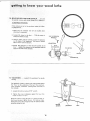
MODEL NO.
113.23801
LATHE ONLY
MODEL NO.
113.238160
AND
113.238180
LATHE WITH MOTOR
Serial
Number
CRRFTSMRH®
Model and serial
number may be found
under belt guard.
You should record both
model and serial number
12-/NCH
WOOD-TURNING
in a safe place for
future use.
CAUTION:
Read
GENERAL
ADDITIONAL
LA THE
®assembly
= operating
, repair parts
and
SAFETY
INSTRUCTIONS
carefully
L_
Sold
by
SEARS,
ROEBUCK
AND
CO.,
Chica_o,
IL.
60684
U,S,,_._
, L
L
FULL ONE YEAR WARRANTY
"
_ :_|f within
one year from
workmanship,
the date of purchase,
ON CRAFTSMAN
this Craftsman
Wood
WOOD LATHE
Lathe
fails due to a defect
in material
or
Seers will repair it, free of charge.
WARRANTY
SERVICE
IS AVAILABLE
SERVICE
CENTER
THROUGHOUT
THE
BY SIMPLY
CONTACTING
UNITED
STATES.
THE
NEAREST
SEARS
STORE
OR
This warranty givesyou specific legal rights, and you may also have other rightswhich vary from state to state.
SEARS, ROEBUCK AND CO.
general
Sears Tower, BSC 41-3. Chicago, IL 60684
safety instructions
for power tooms
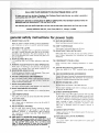
1. KNOW YOUR LATHE
13. SECURE WORKPIECE
Read the owner's manual carefu!ly.
Learn its application
and limitations
as well as its specific potential
hazards.
2.,GROUND
14,
THE LATHE
Mount
workpiece
securely
DON'T
OVERR
EACH
Keep proper
This Lathe is equipped
with
an approved
3_conductor
cordand
a 3-prong grounding
type plug to fit the proper
grounding
type receptacle,
The green conductor
in the
cord is the grounding
wire. Never connect the green wire
to a live terminal.
footing
15, MAINTAIN
between
centers
and balance at all times.
TOOLS WITH CARE
Keep tools sharp and clean for best and safest performance, Follow
instructions
for lubricating
and changing
accessories.
3, KEEP GUARDS IN PLACE
-
in working
order,
and in proper
adjustment
16. DISCONNECT
and align-
men_.
4. REMOVE ADJUSTING
before
ments,
KEYS AND WRENCHES
Form habit of checking
to see that keys and adjusting
wrenches
are removed
from tool before
turning
it on.
Cluttered
areas and benches invite accidents,
not be sl_ppewdue
to wax Or sawdust.
6_ AVOIDDANGEROUS
Don't
them
18.
ENVIRONMENT
wofkspace:
7, KEEP CHILDREN
All visitors
should
AWAY
padlocks,
:
from
work
switches,
or ay removing
or attachment
USE
RECOMM
is in
Follow
the instructions
position
before
plugging
ACCESSORIES
manual
for recommended
that
accompany
the
accessories,
accessories.
accessor es may cause hazards.
19 NEVER STAND
ON LATHE
:
occur
Se_'i0us
attach-
STARTING
"OFF"
ENDED
this owner's
or
injury col,ld
if the Lathe tips over.
il is necessary
to stand
DAMAGED
PARTS
and safer when Operated
Before further use of the Lathe, a guard or other part that
is damaged should be carefu3}V checked to ensure that it
to do a job for which
will operate properly
and perform
its intended function.
Check for alignment
of moving parts, binding.of
moving
parts, breakage of parts, mounting,
ann any other conditions
that may affect its operation,
A guard or other
it
par1
11. WEAR PROPER APPAREL
that
Is damaged
should
[_e properly
repaired
or
replaced.
Do not wear loose clothing,
gloves, neckties or jewetry
(rings;
wristwatchest
to get caught
in moving
parts.
NONSLIP
footwear
is recommended.
Wear orotective
hair covering
to contain
long hair. Roll
long sleeves
aoove the elbow.
GOGGLES
switch
Consult
20. CHECK
10, USE RIGHT TOOL
1Z USE SAFETY
sure
Do not store mater als such that
on. the tool to reach them,
keys.
Don't force tool
was no_ designed.
ACCIDENTAL
Make
in.
accessories
starter
9. USE PROPER SPEED
The Lathe win do the job better
at the proper speed,
changing
area ....
KID,PROOF
master
when
The use of improper
_
be kept a safe distance
8, MAKE WORKSHOP
with
must
Qse power" tools it_ damp Or wet locations Or expose
tO rain. Keep _ork area we/{: lightedi
Provide ade-
quate surrounding
-
Floor
servicing;
17. AVOID
5. KEEP WORK AREA CLEAN
YOUR LATHE
(Head Protection)
Wear safety goggles (must comply with ANSI Z87.1) at all
times. Everyday
eyeglasses only have im pact resistant lenses, they are NOT safety glasses. Also, use face or dust
mask if cutting operation
is dusty, and ear protectors
(plugs or muffs) durin_ extended periods of operation.
2
21. DIRECTION
OF FEED
Apply
cutting too{
of spind{e rotation.
22. NEVER LEAVE
ATTENDED
[o the workpiece
against
LATHE
RUNNING
Don't
leave Lathe untd
the direction
4
Turn power "OF F".
comp',ete stoP.
it comes to a_
addifiona
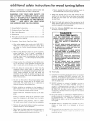
safety instructions [or wood turning lathes
Safety is a combination
of operator
common
sense and
alertness at all times when the Lathe is being used.
j.
Never operate the Lathe with protective
cover
the unused shaft end of the motor removed.
or}
WARNING:
FOR YOUR OWN SAFETY,
DO
NOT ATTEMPT TO OPERATE YOUR LATHE
UNTIL IT IS COMPLETELY ASSEMBLED AND
INSTALLED
ACCORDING
TO THE INSTRUC-
7.
Hang your turning
tools on the wall toward the tailstock end of the Lathe. Do not lay them on the bench
so that you must reach over the revolving workpiece
to select them.
TIONS . , , AND UNTIL YOU HAVE
AND UNDERSTAND
THE FOLLOWING:
8.
Keep firm hold and control
of the turning
tool at all
times. Special caution must be exercised when knots or
voids are exposed to the turning tool.
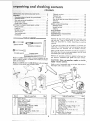
READ
PAGE
1. General
Safety
2, Getting
to Know
Instructions
Your
3. Basic Lathe Operation
4. Maintenance
5. The Lathe
2
..............
13
...................
and motor
19
must be bolted
down
to astand
for stability.
Eyes, Hands, Face, Ears, Body
a. Wear safety goggles that comply "with ANSI Z87.!
1968, and a face shield if operation
is dusty. Wear
ear plugs or muffs
during
extended
periods
of
operation.
b. When turning
between centers or on the faceplate,
always rough-out
"out
of round"
workpieces
at
slow speed. Running
the Lathe too fast, so that it
vibrates,
could cause the workpiece
to be thrown
from the Lathe , . . or the turning toot to be jerked
from your hands.
c. Always revolve the workpiece
by hand before turn_ng on the motor.
If the workpiece
strikes the tool
rest, it could split and be thrown out of the Lathe.
d. Do not allow the turning
tool to "'bite"
into the
workpiece
which
could
result in splitting
of the
workpieee or the workpiece
being thrown from the
Lathe.
Always
position
the tool
rest above the
centedine
of the Lathe for spindle turning.
Do not
apply the turning
tool to the workpiece
below the
Ievet of the tool rest,
e, Do not run the Lathe in the wrong direction.
This
could cause the turning
tool to be thrown
from
your hands. The Lathe must run in a direction
so
that the workpiece
turns toward you.
f.
Before attaching
a workpiece
to the faceptate
always "rough
it out" to as "true round"
as possible.
This wilt minimize vibration
while turning,
Always
plate.
fasten
the
workplece
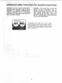
Note the following
DANGER
the front of the belt guard.
15
.........................
or workbench
6. Protection:
..................
Lathe
securely
to
the face
label
which
appears
on
DANGER
FOR
YOUR
OWN
SAFETY:
READ AND UNDERSTAND
THE OWNER'S
MANUAL
BEFORE
OPERATING
MACHINE:
1. WEAR SAFETY GOGGLES PER ANSI Z87.1
AND FACE SHIELD
IF OPERATION
IS
DUSTY,
2, DO NOT WEAR GLOVES, NECKTIES,
OR
LOOSE CLOTHING.
TIE BACK LONG HAIR.
3. BE POSITIVE ALL LOCKS ARE TIGHT BEFORE OPERATING MACHINE.
4. TURN
WORKPIECE
BY HAND
BEFORE
APPLYING POWER TO DETERMINE
IF IT
CLEARS THE TOOL REST OR OTHER MACHINE PARTS:
5. ROUGH OUT FACEPLATE
WORKPIECES
BEFORE INSTALLING
ON FACEPLATE TO
AVOID EXCESSIVE VIBRATION
AND POSSIBLE INJURY.
6. DO NOT MOUNT SPLIT OR CHECKED
WORKPIECE OR ONE CONTAINING
KNOT.
7. ALWAYS
USE
LOWEST
SPEED WHEN
STARTING
A NEW WORKPIECE,
USING
FACEPLATE OR TURNING BETWEEN CENTERS, TO MINIMIZE
POTENTIAL
INJURY.
10. Think Safety.
11. Complete
hand sanding of between*centers
or facepbte
mounted
workpieces
BEFORE
removing
f_om the
lathe. Do not exceed the speed used for the last cutting
operation
performed
with the speed chart.
on the workpiece,
in accordance
12, NEVER
attempt
to remount
a faceplate
turning
to
the faeep!ate
for
any reason. NEVER
attempt
to
remount
a between-centers
turning
if the original
centers in the turning
have been altered or removed,
BE POSITIVE
the lathe is set at the lowest speed if
remounting
a between centers turning with nomaItered
or;ginal centers.
13. Use extra
Failure
to perform
cause the workpiece
these set*up operations
to be thrown
from the
could
Lathe.
g. Avoid
awkward
hand positions,
where a sudden
slip could cause a hand to move into the workpiece.
caution
Jn mounting
a between-centers
or
spindle turning
to the faceptate, or a faceplate turning
to between-centers,
for subsequent
operations.
BE
POSITIVE
the lathe is set at the lowest speed before
turning ON,
14. NEVER
h,
Remove
between
all loose knots before installing
centers or on the faeep!ate.
workpiece
i.
Never leave the Lathe work area with the power on
before the Lathe has come to a complete
stop, or
without
removing and storing the switch key.
checks,
centers.
mount
a workpiece
or loose knots
to
that conta;ns
any sp!its,
a facepiate
or between
15. Do not perform
any ope_atioo when hand hoid]n9 the
wo_kpiece.
Do not mount a ream,:!,_ o_ a d_ill bt *o t!wheadstock spindb.
additional safety instructions for wood turning mathes
WARNING':
DO :NOT: ALLOW FAMILIARITY
(GAINED FROM FREQUENT
USE OF YOUR
MACHINE)
TO BECOME COMMONPLACE,
ALWAYS
REMEMBER
THAT A CARELESS
FRACTION OF A SECOND IS SUFFICIENT TO
INFLICT SEVERE INJURY.
WARNING:
THE FOUR STEP LATHE AND
MOTOR
PULLEYS
FURNISHED
ARE
DESIGNED TO RUN THE LATHE AT THE CORRECT SPEEDS WHEN USED WITH A 1725
R P.M. MOTOR. DO NOT USE A 3450 R.P.M.
MOTOR TO INCREASE THE SPEED BECAUSE
IT COULD
WEAR
BE DANGEROUS.
YOUR
The operation
of an,/ power tool can result
n foreign
objects being thrown
into the eyes, which can result in
severe eve damage. Alway_ wear safety goggles complying
with ANSI Z87.1 (shown on Package} before commencing
power toot operation.
Safety Goggles are available at Sears
retail or cat_ og stores.
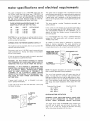
motor
specifications
and
This Lathe is designed to use a 1725 RPM motor only. Do
not use any motor that runs faster than 1725 RPM. tt is
wired for operation
on 1tO_120 volts, 60 Hz., alternating
current. IT MUST NOT BE CONVERTED
TO OPERATE
ON 230 VOLTS.
EVEN THOUGH
SOME OF THE RECOMMENDED
MOTORS ARE DUAL VOLTAGE.
THESE MOTORS HAVE BEEN FOUND TO BE
ACCEPTABLE FOR USE ON THIS TOOL.
HP
RPM
VOLTS
1/3
1/2
1/2
1725
1725
1725
110-120
1t0-120
110-120
CATALOG
electrican
requirements
This power too! is equipped with a 3-conductor
cord and
grounding
type plug which has a grounding prong, approved
by Underwriters'
Laboratories,
The ground conductor
has
a green jacket and is attached
to the tool housing at one
end and to the ground prong in the attachment
plug at the
other end,
This plug requires
outlet as shown.
NO.
a mating
3-conductor
grounded
type
tf the outlet you are planning
to use for this power tool is
of the two prong type DO NOT REMOVE
OR ALTER
THE GROUNDING
PRONG 1N ANY MANNER.
Use an
1250
1278
1279
adapter as shown
to known ground.
and always
connect
the
grounding
CAUTION:
Do not use blower or washing machine motors
or any motor with an automatic
reset overload protector
as their use may be hazardous.
It is recommended
that
replace the TWO prong
THREE prong outlet.
CONNECTING
An adapter as shown below
is available for connecting
plugs to 2-prong
receptacles.
The green grounding
tug
extending
from the adapter must be connected
to a permanent ground such as to a properly
grounded outlet box.
TO POWER SOURCE OUTLET
This machine must be grounded
operator from electric shock,
whi}e in use to protect
the
Plug power cord into a 110-120V
properly
grounded type
outlet protected
by a 15-amp, time delay or Circuit-Saver
fuse or circuit breaker.
If you ar_ not sure that your outlet is properly
have it checked by a qualified
electrician.
MAKE
SURE
THIS
you have a qualified
outiet
with a properly
lug
IS _
CONNECTED
TO A
KNOWN GROUND
grounded,
GROUNDING
i: Z_"-_,l
!: (_,_
ii
'
electrician
grounded
LUG
t
/
e_
ADAPTER
÷
.J "_-
/
3--PRONG
_
PLUG
WARNING:
DO NOT PERMIT
FINGERS
TO TOUCH
THE TERMINALS
OF PLUGS WHEN INSTALLING
OR
REMOVING
THE PLUG TO OR FROM THE OUTLET.
RECEPTACLE
WARNING:
IF
NOT
PROPERLY
GROUNDED
THIS
POWER TOOL CAN INCUR
THE POTENTIAL
HAZARD
OF ELECTRICAL
SHOCK,
PARTICULARLY
WHEN
USED
IN
DAMP
LOCATIONS
IN PROXIMITY
TO
PLUMBING.
IF
AN
ELECTRICAL
SHOCK
OCCURS
THERE fS THE POTENTIAL
OF A SECONDARY
HAZARD
SUCH AS YOUR
HANDS
CONTACTING
THE
CUTTING
TOOL.
if power cord
have it replaced
is worn or cut,
immediately.
or damaged
if yOur unit is for use on fess than
that looks like below.
150 volts
PROPERLY
GROUNDED
i
GROUNDING
PRONG
---_
if you already
The use of any extension
cord will cause some loss of
power.
To keep this to a minimum
and to prevent
overheating and motor burn-out,
use the table below to determine the minimum
wire size (A.W.G.)
extension cord. Use
only 3 wire extension
cords which have 3-prong grounding
type plugs and 3-pole receptacJes which accept the tools
p_ug.
it has a plug
Cord
Length
Wire Size A.W,G.
Upto
100-
100 Ft.
200 Ft.
16
14
200-
400
10
CHECK MOTOR
WARNING:
PLUG
IS
OUTLET
@
_
NOTE: The adapter illustrated
is for use only
have a properly
grounded 2-prong receptacle.
Extension
3-PRONG
PLUG
OUTLET-,_
in any way,
/
Ft.
ROTATION
FOUR YOUR
OWN SAFETY,
MAKE
SURE
NOT
CONNECTED
TO POWER
SOURCE
WHEN
CHANGING
MOTOR
ROTATION.
The motor must rotate CLOCKWISE
when viewed from
the shaft end to which you will mount
the pulley.
(See
page 12.) If it does not. change the direction
according
to the instructions
furnished w_th the motor.
i_:!;_iiii.;_i!il;!::._!_.i;_i!,_'ii-;
i
:_y:ii:ii:L
:/:
:
:
.-::-::
b.._
i¸¸
:
: T ,,tOck
ram,ook........................
.......
:::;::
:
::
:: _'!,!.i;;:::;
;i:.
on rec0mm#ndea
;_:i:
_.. :,., . :,...
Spu_:an_euPcente_instailation
. :..o:
Offandon
switch:;
_.::: i ........
Check motor rotation
............
GETTING
TO KNOW YOUR WOOD
Beitguard
lock .....
.
; .......
,
.
,.
LATHE
- "TOOLS
:i:.
,..
.....
i,
SPeed chart
BASIC LATHE
Framing
square
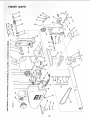
RECOMMENDED
REPAIR PARTS
centers
13
13
14
14
......
............................
OPERATION
..................
15
15
15
16
ACCESSORIES
..........................
18
19
19
..............
21
22
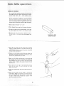
Separate a|l parts from packing materials
and check each
one with the "Table of Loose Parts" to make certain alt
items are accounted
for. before discarding
any packing
material.
I-',_;i
tf any parts are missing, do not attempt
to assemble the
lathe plug in the power cord or turn the switch on unt}l the
missing
parts are obtained
and are installed
correctly.
Using a 7/1 6" wrench, remove the wood blocks attached to
the Lathe. Save the nuts, bolts and washers, you will need
for _ttaching the Lathe to the bench.
!_i
Remove the protective
oil that is applied to the bed. Use
any ordinary
household
type grease and spot remover,
Model 1 t3.23801
Wood Lathe is shipped complete
in one
carton (without
motor,
or bench). The V-Belt anC motor
pulley are furnished.
Model 113.238160
and 1 !3.238180
complete
in one carton and includes
13
'.................
Indexing
..............................
MAINTENANCE
..........................
LUBRICATION
...........................
.,..13
13
13
!3
(medium)
.........
Changing speeds .........................
Spindle turning
.........................
13
NEEDED---
Screwdriver
wrench
.
.
13
3/8- nch wrene
7/1Ginch
7
9:
On - off sw tch ..........................
Spurcenterand
cup center (a!igning
Ta stock
, ,
.
:..
;. 10
;. ; :. , . t2
...._..13
Tool rest lock
..........................
Tool rest base lock
.......................
Handwheei
.............................
-
Taitstocklock
: ;.
; .......
tndex pin ,; ,i,;_i.;;i.
.........
SpindleJock
hole . .......................
7
CAUTION:
Never use gasoline, naptha or similar
highly volatile solvents.
!
Wood Lathe is shipped
a Motor.
A
Apply
a coat of automobile
wax to the bed. Wipe all parts
ghty with a clean dry cloth.
B
MOTOR INCLUDED WITH
MODEL 1 t3.238160 AND
113.238180 ONLY
7
Item
Table of Loose Parts
Item 1
Qty.
.
I
A
B
e
D
E
F
[
J
J
k___.
Motor Pulley
.....................
Belt, "Vee"
112x 37 ................
Wood Turning Lathe
...............
Owner's Manuaf
...................
Belt Guard Assembly
................
Loose Parts Bag _ Part No. 70046
Containing
the following:
Wrench. Hex 5/32 ................
Wrench, Hex 3/16 ................
Screw. Type 23 Pan 10-32 x 3/8 .......
Nut, Hex 3/4-16 .................
Spur, Center
...................
1
1
1
1
1
!
1
1
4
I
1
I
t
6
Table of Loose Parts
Qty.
I
Cu0, Center ....................
Point, Center ...................
Lockwasher
Ext. Tooth No. 10 .......
Key, Switch ....................
Clamp Cord ....................
Bolt Rd. Hd. Carriage 1/4-20x
1-3/4 . . ,
Washer 17/64 x 47/64 x 1/16 ........
Nut Hex 1/4-20
.................
Screw Pan Hd. Ty. A No. 8 x 1/2 ......
6" Tool Rest ...................
Book{el, How To Operate
Your Craftsman
Lathe .............
1!
2
4
1
2
4
4
4
4
1
1
assembly
t2"_3'_J
HOLES
FO,MOTOR-
-0-
(
r
147/0-(
1!
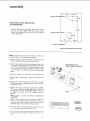
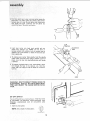
MOUNTING LATHE AND MOTOR
ON WORKBENCH
1. Drill six 3/8" holes
gram to the right.
bench is positioned
or rail underneath.
145/8"
in your bench according to the diaNOTE:
Make sure the top of your
so that you don't drill into the legs
HOLES
FOR
LATHE
,-_----.-_
X\
i
1
t 63/16"
I
RONTO B,NO./T
LOCATION
OF MOUNTING
HOLES
NOTE:
To attach your Lathe to the bench, use the bolts,
outs and washer you removed when unpacking.
2. Position
Lathe on bench and insert two bolts through
holes in headstock but do not screw on the nuts.
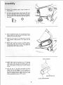
3.
Position the Lathe so that the bed is parallel to the front
of the bench. Check the foot, If the bottom
of the foot
is not flat on the surface of the bench, loosen the screw
in the foot, tap the screw to loosen the Iocknut inside.
Turn the foot so it is flat on the bench and tighten the
screw.
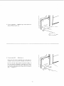
4. Mark
the
5, Remove
foot,
location
on
the Lathe
and
the
ddll
bench
of
a 3/8"
the hole
hole
BED PARALLEL
TO
FRONT EDGE OF BENCH
in foot•
to attach
the
6, Position
the Lathe and insert the bolts from the top.
Pface a fiat washer, a Iockwasher
and a nut on the bolts
and tighten the nuts,
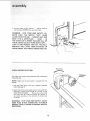
Position
the motor
over the mounting
holes.
NOTE"
When using a Craftsman
double shaft motor, make sure
the 5/8" dia. shaft is to the left when facing the front of
the Lathe• For motors
with a !/2"
diameter
shaft see
Step 15.
NOTE:
Motor
113•238180.
NOTE:
is included
The ventilation
with
Model
113,238160
holes in the motor
should
FOOl
and
NOT
face upward as sawdust can collect inside the motor,
tf
necessary, loosen the two motor base cFamp screws and
rotate the motor, Then, tighten the clamp screws.
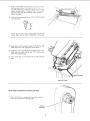
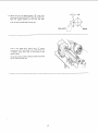
8. Find
from
four 1-3/4"
carriage bolts, flat washers
among the loose parts (see illustration),
and nuts
9. Insert the bolts from the top. Place a flat washer aod a
nut on the bolts but do not tighten
the nuts at this
time.
1 3/4
10;Re_n_e
the: headstock
- = scre_Wrench_
_
1-i. Find
and
:
four
four
pu_l!ey using
_:
the
5/32"
set-
pan head thread cutting
screws 3/8" long
Iockwashers
from
among
the loose parts,
Attach the belt
ere, The arrows
guard with these screws and Iockwashin this illustration
show the location of
the screws.
12.
P|ace the headstock pulley
onto the headstock
shown, Position
it so that the end of the pulley
with
theend
shaft as
is ftush
/
of the lathe spindle.
13,
Place the motor pulley on the motor shaft so that the
small diameter
is approximately
1/16" away from the
motor.
14.
NOTE: When installing
the pulley on a 5/8" diameter
motor
shaft,
make sure that the 3/16"
square key
furnished
with your motor is in place. Then tighten the
setscrew with a 5/32" setscrew wrench.
i
/
/
/
/
/
i -¸ i ¸
3/16
15.
NOTE:
motor
x 3/16
KEY
When installing the pulley on a 112" diameter
shaft,
make sure that the adapter
sleeve and
3/16"
square key furnished
with your motor
are in
place. Then tighten the setscrew with a 5/32"
setscrew
wrench.
16,
Place the belt on the pulieys and slide the motor
toward the rear of workbench
until ait the slack is removed from
the belt. NOTE:
1/2 inch deflection
of
belt under moderate pressure applied between the two
pulleys is adequate tension, Tighten
only two of the
motor mounting
bolts using a 7/t6,
wrench.
J
ADAPTER
1/2 DIA.
MOTOR
SHAFT
SLEEVE
17.Place
a straightedge
suchasapieceo_wood,metalor
framingsquare
across
thepulleysto seeif [heya_ein
linewitheachother,tf theyare,tighte_d_eothe_
*.wo
motormounting
bolts.If theyarenot in line,toosen
thetwomotorboltsandmovethemotorsideways...
tightenthebolts.
18.Findfourpanheadwoodscrews
1/2"tongfromamong
theloose
parts.
Attachthebeltguardplatetothebenchwiththetwo
screws.
MakesuretheplateisPARALLEL
to thebelt.
19.Plugmotorcordintooutletonbackof switchbox.DO
NOTplugmotorcordintopowersource
outlet.
20.Position
thetwocordsasshown
andclampthemto the
tabtewith two cableclamps
and1/2" woodscrews
fromtheloosepartsbag.
21.Coiluptheslackinthecordandtie it withapieceof
tape.
CABLE
CLAMPS
MOTOR
CORD
SPUR AND CUP!CENTER
INSTALLATION
1. Find a 3/4q6 hex nut among the loose parts and screw
onto head stock spindle until finger tight,
3/4-!6
HEX NUT
2..F_n_
two pointsanda spurandcupcenteramong
the
looseparts.To insertpointintocenters,
placecenter
between,
jawsof a vise. DO not tighten vice. Insert point
into center
and wltfr a hammer
and nail
around the base of the point until secure.
gently
tap
\
\
CUP
\
\
Insert
spur center
into head stock spindle
and cup
center into
tailstock
ram.
NOTE:
Do not drive or
hammer
centers into ,pindle or ram as removal may be
difficulL
Use a soft hammer or block of wood and give
them a gentle tap.
To remove
pulley
with
ptiers,
turn
isejected.
.TAILSTOCK
RAM
spur cen_er from spindle,
ho_d the spindle
one hand, and, using a wrench
or pair of
the hex nut counterclockwise
until center
& To remove cup center insert a 114" wood dowel or brass
rod through
the hole in the tailstock
ram. Hold the
center with
one hand and rap the dowel or rod with a
hammer.
FOOT
WARNING: DON'TCONNECT
POWER CORD TO
ELECTRICAL
OUTLET IN YOUR SHOP UNTIL
YOU ARE READY TO CHECK MOTOR ROTATION.
ON-OFF
SWITCH
The On-Off Switch has a locking feature. THIS FEATURE
IS tNTENDED
TO PREVENT
UNAUTHORIZED
AND
POSSIBLE
HAZARDOUS
USE
BY CHILDREN
AND
OTH E RS.
1. Insert key
NOTE:
into switch.
Key is made of yellow
,_,.
KEY
plastic.
[y_LLOVz
KEY
P_ AST _C
10
2. To turn
and pull
Lathe ON .., _NSERT
END of switch out.
3. To turn
Lathe OFF
...
finger
under
switch
lever
PUSH lever in.
Never leave the Lathe unattended
until
complete
stop and you have removed
it has come to a
the switch
key.
Do not cycle the motor switch
on and off rapidly,
as
this may cause the faceplate
or sanding disc to !oosen.
In the event this should ever occur, stand clear of the
face plate or sanding disc untit it has come to a complete
stop, .. retighten it.
11
4. To lock switch
in OFF
with one hand, REMOVE
position
key with
.
HOLD switch
other hand.
IN
WARNING:
FOR YOUR OWN SAFETY, ALWAYS
LOCK
THE SWITCH
"OFF".
WHEN
LATHE IS NOT IN USE ,. , REMOVE KEY AND
KEEP IT IN A SAFE PLACE . ..ALSO,..
IN
THE EVENT OF A POWER FAILURE
(ALL OF
YOUR LIGHTS GO OUT) TURN SWITCH OFF...
LOCK IT AND REMOVE THE KEY. THIS WILL
PREVENT THE LATHE FROM STARTING
UP
AGAIN WHEN THE POWER COMES BACK ON.
HOLD
I
PULL
\
\
ROTATION
CHECK MOTOR ROTATION
The Lathe
must rotate counterclockwise
the spindle
end.
NOTE:
Make
sure
the
spur
when viewed
center is removed
from
TERMINAL
COVER
from
the
spindle.
1, Plug the Lathe power
oudet (See page 4}.
2. Stand
cord
into
clear of the Lathe spindle
a properly
and turn
grounded
the switch
ON.
Notice the rotation
of the spindle
If it is NOT [urning
COUNTERCLOCKWISE
. . _ Remove the Lathe power
cord plug from
the outlet
and change the rotation
of
the motor
according
to the directions
furnished
with
the motor.
WARNING:
FOR YOUR OWN SAFETY, MAKE
SURE PLUG IS NOT CONNECTED
TO POWER
SOURCE OUTLET WHEN CHANGING
MOTOR
ROTATION,
12
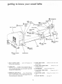
getting
to know
your
wood
lathe
HANDWHEEL
10
1NDEX
BELT
PIN
SPUR
CENTER
SPINDLE
LOCK
HOLE
10
7
GUARD
TOOL
TOOL
BASE
REST
TAILSTOCK
CUP CENTER
RAM
TAILSTOCK
/
RAM
REST
"_
TOOL
BASE
\\
/
11TAILSTOOK
FOOT
\
\
SPEED
TAILSTOCK
LOCK
TOOL/REST
LOCK
BED
SWITCH
ON-OFF
BELTGUARD
LOC K
HEADSTOCK
4. TOOL REST LOCK . . .Ciamp the too; rest to the
1. BELT GUARD
LOCK
. . . Locks the hinged part of
the guard during operation.
tool rest base:
5. TOOL REST BASE LOCK
2. INDEX
PIN .
. . . Clan_ps the too_
rest base to the bed,
, . Engages with the spindle pulley to
determine
equal spacing for cuts for fluting or feeding,
or for dividing
face plate work.
DO NOT USE FOR
REMOVING
FACEPLATES.
6. HANDWHEEL
7. TAtLSTOCK
... Adiuststhe tailstock ram.
RAM LOCK
. . . Clamps tfle ram in
the taitstock.
3. SPINDLE
LOCK HOLE...
For removing faceplates or sanding discs. Insert a setscrew wrench, large
nail or bolt in the hole to hold the spindle while unscrewing faceplate or sanding disc,
8, TAILSTOCK
LOCK,
. . Clamps the [aiistock to the
bed.
9. ON-OFF SWITCH .....
13
Seepage 10.
geffing
fo know
10. SPUR:CENTER
for
spindle
AND CUP CENTER..
turning
ALIGNING
and should
always
•. are used
be in alignment.
CENTERS
If the centers are not in line as shown,
ing adjustments.
I.
your wood
Make sure the tailstock
checking for aiignment
2. Loosen the screw
loosen the Focknut
and
in the foot
inside.
make the follow-
ram are locked
. . TAP
when
the screw to
3/16" SETSCREW
WRENCH
\
3. Using a 3/16"
setscrew wrench, loosen the setscrew
on the back of the headstock.
The screw is located
about !-3/4"
from the bottom.
F
HEADSTOCK
4. Swing
the taiL_tock
so that the two F)oints are in
line . , . tighten the setscrew in the headstock
and the
screw in the end of the tailstock.
FOOT
3/16"
SETSCREW I
V
O
,
'_
TAI LSTOCK
_
HANDWHEEL
11. TAILSTOCK
....
supports the workpiece for spindle
turning.
The taifstook
contains a brass screw which Dears against
the "key"
on the underside
of the bed. This screw prevents excessive "looseness"
(rocking
back and forth} of
the tailstock.
1, Loosen
the tocknut
using a 7/16"
2. Tighten
the screw moderately
loosen it about t/4 turn.
P
wrench.
against
the key,
then
Slide the tai]stock
along the bed. I f it does not stick or
bind in any one spot, tighten the nut. If it binds or sticks,
loosen the screw ordy enough so that the tailstock
slides
smoothly
al ong the bed.
BRASS
SCREW
__i__ii_i
:_!i:ii_!!
_i_:_
i_
__/_,iiii_:i_i_
__:
_ii_i_i!_/_
_/,i_
_!i_,_,
__,
14
\
LOCKNUT
KEY
i ¸
12, SPEED CHART
speeds for various
....
Indicates generalrecommended
sizes of workpieces.
basic lathe
CHANGING
operations
SPEEDS
The belt is shown positioned
on the second steps from
the outside end of the pulleys. This causes the lathe to
run 2250
MOTOR
COUNTERCLOCKWISE
PULLEY
R,P.M.
Suppose you wish to run the lathe slower
R.P.M. You must shift the belt inward.
1, Make sure the
power cord
2, With the belt guard
COUNTERCLOCKWISE
pushing
to rotate
until
motor
is removed
from
- say, t350
the outlet.
raised, rotate the motor
puiley
with your
teft hand while
on the belt with
3, Continue
belt
ROTATE
your right
the
it "climbs"
pulley
down
hand.
while
into
pushing
the third
on the
ON
BE LT
step of the
pulley.
4. Nowrotatethe
spindle
pulley
CLOCKWISE
with
yo_r
right hand while pushing on the belt with your left
hand. The belt will climb up into, the third step of the
spindle pulley.
To make the lathe go faster,
ward.
1. Rotate
right
until
the
right
pulley
yourteft
the motor
pulley
hand while
be shifted
CLOCKWISE
hand. Pul! on the beet whiie
it climbs down
into the
2. Now rotate
with
spindle
the belt must
with
out/'SPINDLE
your
PULLEY
rotating
the pulley
next
smaller step.
COUNTERCLOCKWISE
pulling
on the
belt with
your
hand, The belt will c_imb up into the next larger
step.
15
asnc lathe
"b
¸ ,
operatRons
_
SPINDLE
If you
TURNING.
have never done any amount
we suggest
turning
that
you practice
tools.
Start
with
a smatl
Be sure to study the "'Handbook"
with
your lathe.
use of
!t explains
the turning
2. Draw
diagonal
which
4. The other
2" x 2" x 12".
line.
This
is for
end is for the cup center.
the cup center
the correct
of the tool
lines on each end to locate
diagonal
turning;
to hefp you gain experience.
3. On one end, make asaw cut approximately
on each
turning,
you received
the positioning
restand other information
a piece of wood
spindle
and illustrates
toots,
1 Select
of wooc
using the various wood
on the wood
where
the
the centers
1/16" deep
spur
center,
Place the point
the diagonal
of
lines
DIAGONAL
ON BOTH
cross
5,
;
Dri#e
tt_e cup center
into
the wood.
Use a wooden
mallet or a plastic hammer. If you don't
a Sleet hamme_, but put a piece of wood
{h e
have one, use
on the end of
it.
:&Remove
the cup::Center ahd drive the spur center into
life ether end:0f the wood. Make sure the spurs are in
: the :saw cutSl
Rem0Ve
the spur center
i
7. Make Su lethe
centers and the hole in the spindle and
the tailstock ram are clean. Insert the spur center into
the headstock
and the cup center
into the tailstock
and tap them in rightly with a piece of wood. Do not
drive them in;
8. Put a drop of Oilor
wax on the wood where it contacts the cup center.
This will lubricate
the wood
Wf_ile it _s turning,
9. Place
stock,
the wood
between
the centers
and lock
the tail-
I0. Move the cup center into the wood
by turning
the
hand wl_eel. Make sure that the cup center and spur
center are "seated"
into the wood in the holes made
insteps
5 and6
above. Rotate
the wood by hand
while tUrning the hand wheel.
: :
......
....
t6
LINES
ENDS
1t.
I/8"
Adjust the tool rest approximately
1/8" away from
the corners of the wood and 1/8'" above the center line.
Note
Lock
the
angted
the tool
position
of
the
tool
rest
base.
rest base and the tool rest,
TOOL
Look at the speed chart.
Notice that a 2" square
turning up to 18" tong should run at 875 R.P.M. for
"roughing"
Move
slowest speed,
the
V-belt
on the
pulleys
to
the
Rotate the wood by hand to make sure that the corners
do not strike the tool rest.
17
REST
WOOD
INDEXING
]he spindle pulley contains 36 equalty spaced holes, The
index pin engages with these holes to keep the spindle
from turning
white you put a mark on the workpiece,
For example:
wheel:
To locate
the position
of six spokes
in a
1, Pull the index pin outward and turn it so that the small
cross pin slips into the slot, This wilt allow the index
pin to engage in one of the holes in the pulley and prevent the spindle from turning.
2. Adjust
the tool rest
and make a mark.
approximately
at the centerline
3, Puiioutthe
index pin and slowly rotate the workpiece
until _he pin slides into the next h01e in the pulley,
4iD6
:
1:his six: times
t$nue this
aParti
andput
the next rn a r k on the work-
marks wilt be space d 600 apart. ConOperation
until six spokes are marked 60 _
:
:
5. Spindle
turnings
Can be divided
in the same manner.
18
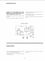
maintenance
WARNING:
FOR YOUR OWN SAFETY, TURN
SWITCH "OFF"
AND REMOVE PLUG FROM
POWER SOURCE OUTLET BEFORE MAINTAINING OR LUBRICATING
YOUR LATHE.
Frequently
the motor.
blow
out
any dust that
may accumulate
to keep the surfaces clean and allow
stock to more more freely.
wax applied
rest and taif-
If the power cord is worn or cut, or damaged
have it replaced immediately.
in any way,
inside
For motor
motor.
A coat of automobile-type
the tool
maintenance,
follow
instructions
furnished
with
to the bed will help
WIRING
t
DIAGRAM
WHITE
MOTOR
f
BLACI_
CORD
m
...........
I1!
i llq-'
II!11
-m
nubrication
For motor
the motor.
All of the BALL BEARINGS
are packed with grease at the
factory. They require no f'._rther lubrication.
Periodically
lubricate
the ram in the tailstock
with
No. 20
or No, 30 engine oil.
19
lubrication,
follow
instructions
furnished
w th
:trouble shooting
TROUBLE
.,
u
im,,,,,,,,,,, ..................
TROUBLE
Motor
wilt not run.
Lathe
slows d own
when
turning
Tailstock
rocks
back and forth
PROBABLE
SHOOTING
CHART
,,
.....
CAUSE
...........................
1, Defective
On-Off switch.
Defective sw:itch cord.
Defective sw_tch box receptacle.
2, Motor protector
open,
(only if your motor is
equipped with an
overload protector).
Other cause
1. Replace
again.
1. V-belt
1. Adjust
too loose
1, Brass adjusting
loose.
screw is too
,,
u,,,,,,,,,,,,,,,,,,,
R EM"EDY
defective
parts
before
using
Lathe
2. Consult Sears Service. Any attempt
to repair this
motor may create a HAZARD
utlless repair is
done by a qualified
service technician.
Repair
service is available at your nearest Sears Store.
belt tension,
see Assembly
1. Adjust screw. See Section,
Your Lathe".
Section.
"Getting
To Know
excessively.
Headstock
on bed.
loose
Wood burns at
taiist0ck
end.
1. Setscrew
not tight,
f. Cup center
}ubricated.
too tight
1. Tighten setscrew. See Section,
Know Your Lathe".
or not
!:
2O
I.
"'Getting
Back off tailstock
ram and lubricate
cup center. See Basic Lathe Operation
Section, "Spindle Turning."
To
recommended
accessories
RECOMMENDED
ACCESSOR! ES
ITEM
CAT.
Work Bench .............
9-10266, 9-10278,
Motor Pulley (Four Step) I/2"' Bore ..........
Moto_ Pulley (Four Step) 5/8" Bore ..........
Drill Chuck 1/2" Capacity
with
No. 1 M,T. Shank ....................
Work Arbor
1/2" D_a. with
No, 1 M.T. Shank ....................
Screw Center with No. 1 M,T, Shank
Ball Bearing Center with
No. I M.T. Shank ....................
60°Center
with No. 1 M.T. Shank
.........
...........
Face Plate, 4" Dia. with 3/4"
No. t6 Threads 9 holes .................
Face P|ate Including Spurs and Screw
3" Dia, with 3/4'" No, 16 Threads
Sanding Table
........................
9" Dia. Sanding Disc Only with 3/4"
No. 16 Threads ......................
Turning Toots
.................
Draw Bolt w_th 1/4" No. 20 Threads
Power Tool Know Handbooks
Radial Saw ..........................
Table Saw ...........................
Bowl Turning Tootrest ...................
Face Plate 6" with 3/4"
No. 16 Threads 6 holes .................
Copy Crafter
.........................
Speed Reducer ........................
Face Plate 4" dia. with 3/4'"
No. 16 Threads, Cast Iron, 6 holes
The
above
available
recommended
at the time
accessories
this manual
21
NO.
9-10271
9-27921
9-27922
9-22342
9-21532
9-21164
9-21122
9-21102
9-2489
Center
.........
9-20912
9-24922
9-24906
(SEE CATALOG)
.........
9-21542
9-2917
9-2918
9-24903
9-24904
9-24907
9-23895
.........
are current
was printed.
9-23865
and were
repair
parts
\
\
P_
22
0
c0
£
(n
¢,4
D_
C
w,,%.._D
o
,:.o
£
10
(%t
• uo
%,.-
0
O0
¢0
e4
_00oooooo_o
t--
o
_
i'-,., m.
¢oo
o
0
,-o
_--
p-
f--
1--
_0
09
_
r/)
P... r.. o
ooo
o
_-_
Z
_-_
%....
,5
Z
UJ
0
U.I
,.r.
I--
<
_t
Z:53
0
Z
z
o
g
if2
=
I-
0
0
>_0
.£
_._
.s+
0
L'N
iI
_
m
_
z
<
oo
t-
<
+ +
'--
+o
0
o
z
_6
F-
_z
-_
23
Z
o
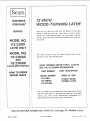
?2-iNCH
WOOD°TURNING
owners
manual
SERVICE
Now
that
should
you
have purc'nased
a need
contact
any
ever
Sears
and Co. stores.
MODEL NO.
113.23801
exist
Service
for
your
LATHE
12"
repair
Center
Be sure to provide
Wood-Turning
parts
and
or
Lathe
service,
simply
most
Sears,
Roebuck
all pertinent
facts
when you
catl or visit.
LATHE ONLY
MODEL NO.
113.238160
The model number of your 12" Wood-Turning
found on a plate under the belt guard.
Lathe will be
AND
113.238180
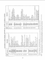
WHEN ORDERING REPAIR PARTS, ALWAYS
GIVE THE FOLLOWING
INFORMATION:
LATHE WiTH MOTOR
PART
HOW TO ORDER
REPAIR PARTS
NUMBER
MODEL
PART
DESCRIPTION
NAME
NUMBER
113.23801
12-INCH
TURNING
113.238160
OF iTEM
WOOD
LATHE
113.238180
All parts listed may be ordered from any Sears Service Center
and most Sears stores. If the parts you need are not stocked
Iocatty, your order witl be electronically
transmitted
to a
Sears Repair Parts Distribution
Sold
Part No. 70045
by
SEARS,
ROEBUCK
AND
Form
No.
CO.,
SP4322-4
Center for handling,
Chicago,
IL.
60684
Printed
U.S.A.
in U.S,A.
t/81