1
SE/41RS
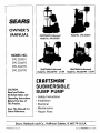
OWNER'S
MANUAL
CRAFTSMANProfessional
Model No. 390.305001
Model No. 390.304692
MODEL NO.
390.305001
390.304692
390.304790
390.305790
CRAFTSMANProfessional
Model No. 390.304790-
1/3 HP
CRAFTSMANProfessional
Model No. 390.305790-
1/2 HP
[RRFTSMRW
CAUTION:
Read and Fallow
All Safety Rulesand
Operating Instructions
Before First Use of
ThisProduct.
Save ThisManual For
Future Reference.
SUBMERSIBLE
SUMP PUMP
• Safety Instructions
• Installation
• Electrical
• Maintenance
• Repair Parts
Sears, Roebuck and Co., Hoffman Estates, IL 60179
PRINTED
IN
U.S.A.
U.S.A.
Form No.
F642-9812
(Rev. 3/16/04)
CONTENTS
INTRODUCTION
INTROD UCT[O N/%V.M_A Nq _,
SAFETY
2
2-5
UCW
punlp
INS'I ALLATION
OPEI(ATION
LIlt
FRI( _.L
MAIN1 l_N_N( E
bt R\ I( E
PARTS
5-4
\icc
Irom
th,u
re,uh
due
to
chooser
that
a defect
to have
LIFETIME
it is installed
m
mat_tal
Sears
ittld
or
mstall
WARRANTY
opel-area
wot'l_lai_htp,
year from
the date
two years
ttlstnlCtlons
it to )'our
in
nearest
lu_trtlCtlOl'iS
thl,
it
It _ ill .ilso
from
k\,lrr,
owner's
store,
W service
is available
help
€_.ltl,_t',
if tills
sou
obtam
\ ntt
hill
,l\ _)id
%vc Lalll3OI
inb[,ll[
and
\ .tJttc
.llld
net_die,,
cqll'tll¢)[
LISC %otlr
good
,t n
.l[Id
Seat",
wifi
SUBMERSIBLE
pump
t_placc
ever
tt fr_e
Sears
will repair
from
ON
the date
on CRAFTSMAN
or replace
this
pump,
fails
fi)r
tile
of charge
CRAFTSMAN
of purchase,
Sears
® SUBMERSIBLE
free of charge
ff defectwe
,er-
ic_ cost,
t_anl'tOt
(_o\'t.q
PUMPS
orlgUlal
purcllaber
_t Otl pa3
f()r
labor
zf ,, oct
furnish,
free
of charge,
by calling
Sears
PUMPS
in material
® 113-HP SUBMERSIBLE
wdl
or workmanship
SUMP
a replacement
This warranty does not cover repairs or replacement parts necessary, because of abuse or neghgence
ate this pump according to the mstructions in the owner's manual
W_
)ntl
lll[\
manual
arid
belt)Ft'
\\ ill help
® PROFESSIONAL
tile
Sears
()Lit
pump
WARRANTY
_gh
the
YEAR WARRANTY
of purchase,
LIMITED
After one year and
pay for labor.
to
return
the replacement
FULL ONE
For one
on CRAFTSMAN
according
rL'ad
111 otlr
i-:,
-_
(_--
LIMITED
Provided
Plca',c
PUMPS
part
for an_ defectt_
failure to install
lflClUdlllg
e part
You
adlUst and oper-
at 1-800-4-MY-HOME*.
LIABILITY
LIMITATION
Sears is not hahle for loss or danmge to property, nor for any mcidental or consequentvtl loss or expense from propem damage, that results dJcectty or indirectly from the use of thxsproduct Some states do not allow the exclusion or Imntattonof properq, mctdental or consequential
dam_gest,so the above limitation or exchtston may not apply to )ou
This walx'am_appl_ only while tills product ts used m the United States
This warranty
gives you Specific legal rights, and you ma_ also have other rights whmh vary from state to state
Sears, Roebuck
and Co., Dept.
GENERAL
Carefully
read
manual
or on
and follow
pump.
all safety
817_fA,
SAFETY
instructions
in this
,tnup
personal
mjury, death
slur3,,
[_ CAUTION ]warns
minor
personal
The word
tmportant
that will
or malor property
l/a, WARNING_ warns abnut
rious personal
nored
hazards
death
about
hazards
damage
hazards
property
that
damage
NOTICE mdtcates spectal
but not related to hazards
will
or can
se-
3
tf ig-
cause
which
cofinl"tt)tt
ro a\oid
task or serious
ag_,
safety
read
_LImp
Ilndll_
in._trtlctlons
lil_talhtlg
pLin'tp
b¢:_
sttnlp
pLIn'tp
inlm 3 and
careftlll_
a
b_t'x
secondat3.
i¢.e",
ptt)blem_
al'td
propem
b_tnre
Page
dam-
lnstalhng
_To
lows
if pump
nation,il
pump
plumbmg
avoid fatal shocks,
needs servicing:
and
proceed
electrical
as fol-
A.Disconnect
power
to pump
outlet
box before
pulling
pump
cord
plug. Alter plug _s pulled, let
pnmp cool for 20 mmutes hcfore attempting
to work
on _t Modern motors ma_ operate
at high temperaCures
ff tguored
mstructions
about
about
stoic
kup
2 Follow local and/or
codes when installing
ff tgnored
damage
or a DCbac
pump
serious
that will or can cause
or ntalor
mjut T or property
cause
IL 60179
Local Sears
}our
I_tttnp
O, for nlh)inlatton
renledlcs
This is the safety alert symbol.
XXqaen you see tlu_
symbol on your pump or m thts manual, luok for one
of the followmg
stgnal words and he alert to the potential
for personal inltn T'
about
Estates,
INFORMATION
Con_tllt
_i
warns
Hoffman
are
B Take
duce
Elecmcally
powered
sump ptunps non-nally gi_ e man}' ",'ears
of trouble-free
servtce when correctly mstal[ed, maintamcd,
and used However,
unusual ctrcumstances
(interruption
of
power to the pump, dirt/debris
m the sump, floodmg that exceeds the pump's capactty, elecmcal or mechanical
fadure m
the pump, etc ) may prevent )'our pump from functtomng
normally
To prevent possible water damage dne to floodmg,
stand
C Ground
extreme
the chance
m water
the
care
when
changing
fuses.
To reot latal electrical
shocks,
DO NOT
or put
clecttac,il
\ our
outlet
linger
iu th_
D Use only
an individual
branch
Ground
Fault Circuit Interrupter
grounded
outlet for cord plug.
2
[lime socket
hox
circuit
with
(GFCI) protected
a
SAFETY
/ INSTALLATION
4. Never
run pump
dry. To do so can damage
internal
parts, ovcrheat the pump (which can cause bums to people handling or servicing the pump), and will void the
warraoty
I.
"_ DO NOT attcmI_t n) oil the i)uml) motor A special oil has
been put into the motor housing at tilt" lhctot%': use ol any
other oil will vuid the warranty
and could damage the
pump.
6. This pump is recommended
for use in permanent
latinns only. This pump has not been invenstigatcd
in swimming
pool areas.
instalfor use
not use
in explosive
atmospheres.
Pump water only with this pump.
Failure to follow
this warning
can result in personal
injury
and/or
property
damage.
8. Release all pressure
any component.
9. Drain water
within
the system
from the system
before
before
servicing
servicing.
10. Secure the discharge line before starting the pump. An unsecnred
discharge
line will whip, possible causing personal injury and/or property damage.
11. Periodi _'callyinspect pump and system components.
Pergoml
routine maintenance
as required (See MAINTENANCE).
12. Provide a means of pressure relief for pumps
charge line can be shut-off or obstructed.
13. Personal
ADDITIONAL
whose
dis-
THE
visitors
at a safe distance
from the work
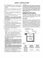
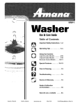
Locate sump at lowest place in basement
or drained area.
Floor drains or drain tiles can also be tiled into sump.
Minimum
sump size is 12" (305mm)
in diameter
by 24"
(610mm)
deep for model 390.305001
and 10" (254mm)
in
diameter
by 20" deep (508mm)
for models 390.304692,
390.304790
and 390.305790.
Periodically inspect pump, system components,
and sump for debris and foreign objects.
Keep sump free from all refuse.
Perform
routine
maintenance
as required.
Use a sump cover to exclude
refuse
from sump. Consult local code for cover specifications.
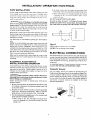
Grounded, GFCl _
Protrected Outlet
reduce
the
risk
of electric
Where
a 2-prong
wall receptacle
must be replaced
with a properly
receptacle
installed
in accordance
Electrical
Code and local codes
-,,,
master
15.Protect
electrical cord from sharp objects, hot surfaces,
oil, and chemicals.
Avoid kinking the cord. Replace or repair damaged or worn cords immediately.
16. Do not handle a pump or pump motor with wet hands or
when standing on a wet or damp surface, or in water.
-,,,
Sump Pit
Minimum
Diameter (D)
_
',
'
Minimum
Depth (H)
shock,
is encountered,
it
grounded
3-prong
with the National
and ordinances.
Basement Floor
,\\\\\\\xxxx\_.\
area.
pull plug before
servicing.
This pmnp has not been
investigated
for use in swinlming
pool areas. This
pump is supplied
with a grounding
conductor
and
grounding-type
attachment
plug. Be certain
that it
is connected
only to a properly
grounded
groundlug-type
receptacle.
.
_"[_
Sump Cover
14. This equipment is only for use on 115 volt (single phase)
and is equipped
with an approved
3-conductor
cord and
3-prong, grounding-type
plug.
f AWARNING]To
Separately)
SUMP
Safety:
d. Make workshop
child-proof
- with padlocks,
switches,
and by removing starter keys.
(Purchase
Sump Pump Hose Kit, SEARS Stock No. 27909, containing
24' (7.3M) of 1-1/4" flexible plastic
pipe, 1-1/4" plastic
adapter and stainless steel clamp. We recommend
a Check
Valve, SEARS Stock No. 2789 or 2792.
a. Wear safety glasses at all times when working
with
pumps.
b. Keep work
area clean,
tmcluttered
and properly
lighted - replace all unused tools and equipment.
c. Keep
INSTALLATION
MATERIALS
7. Know the pump application,
limitations,
and potential
hazards. Not lbr use with salt water or brine.
_Do
&WARNING [Risk of electric
shock.
If your basement
has water or moisture
on the floor, do not walk on wet
area until all power
has been turned off. If shut-off
box is in ba_sement,
call the electric
company
to shutoff service
to the house,
or call your local fire departnlent
for instructions.
Remove
pump
and repair or
replace.
Failure
to follow
this warning
can result
in
fatal electrical
shock.
_F
Figure
I
Pump
Model
Minimum
Diameter (D)
Minimum
Depth (H)
300.305001
12" (305mm)
24" (610ram)
10" (254mm)
20" (508mm)
390.304692
390,304790
390.305790
INSTALLATION
PUMP
/ OPERATION
INSTALLATION
/ ELECTRICAL
B. As water comes into the sump,
switch rises to an upward position
Set the pump on the bottom of the sump, making sure that
it sits solidly and is level. Be sure there is enough
space
around the punlp to allow the switch frec mo_ cnlcnt ;is the
stimp water level changes.
Du Rot iitstall the ptimp on clay,
earth, or sand surlTace.
tile auton/atic
and the pump
float
starts.
(7. Water will contint_e to be pumped until the float switch
is hanging
ill the
dox_nward
position
agaiit,
when
pump will stop.
DO NOT ALLOW PUMP TO RUN DRY!
i
Be sure to leave at least 5" (127mm)
of water
above
pump
base plate when
pump
stops.
Running
pump
dry could ruin the pump and will void the warranty.
I_"
CAUTION IIRisk of flooding.
.
If a flexible
discharge
hose is used, pump
may move around
in sump when
niotor
starts.
If it moves far enough so that tile switch hits
the side of the sump, the switch may stick and prevent
pump from starting. Make sure that pump is secured so that
it cannot walk arotmd in sump.
Hose Kit No. 27909 can be used as the discharge
pipe. Run
the discharge pipe to the nearest sewer outlet or other point
of disposal. Use the most direct route and the fewest turns
and elbows possible.
Use Teflon
only.
tape to seal threads
in plastic
pipe.
Hand tighten
NOTE: To avoid backflow into sump when pump shuts off,
install a Check Valve, SEARS Stock No. 2789, in threaded discharge port of pump. A SEARS No. 2789 Check Valve is constructed with an anti-aiflock hole. If you use a SEARS No. 2792
or any other check valve, drill a 1/8" hole in the discharge pipe
just above the pump discharge
port and below the Check
Valve to prevent pump from airlocking.
Figure
NOTICE:
Testing
with
is recom-
for Ground
factory
1. Be sure automatic float can swing freely through its entire
arc without
interference
from pump, piping, sump wall
or any other object.
UL Listed
2. Plug the automatic
switch cord into a properly grounded
outlet (see "Electrical
Connections",
Page 4). Plug the
pump power cord into the back of the switch plug.
3. Test the installation
by adding water to the sump pit until
pump operates
normally as follows:
A.When
sump is dry, the watertight
switch is hanging
in a downward
pump is off.
circuit
CORD.
For your safety, check
your outlet for ground
using an
Underwriters
Laboratory Listed Circuit Analyzer (Figure 3A).
A Circuit Analyzer will tell you by a pattern of lights if the
power, neutral, and ground wires are correctly
connected
to your outlet. It can also be used to check other outlets in
your home. A Circuit Analyzer
is available
in the Sears
Electrical Department.
IAWARNING_ Risk of electric
shock.
Always disconnect
the pump and switch from the electrical
power
source
before
doing any maintenance!
pump
electric plug. The third prong
prevent possible fatal shock.
be removed.
Your electrical
polarized
type with an inter-
An individual
branch
15 amp electrical
mended. DO NOT USE AN EXTENSION
Your SEARS Model 390.305001
Submersible
Drainer comes
with the automatic
float switch mounted
on the motor housing ready for operation.
Tether
length is factory set at 3"
(76mm). Do not change tether length. See Page 6 for vertical float switch instructions.
to install
CONNECTIONS
The Sump Pump has a 3-prong
is used to ground the pump to
The third prong should never
outlet should be the 3-prong,
nal ground.
AUTOMATIC
FLOAT SWITCH
INSTALLATION
AND OPERATION
below
Do not change tether length.
ELECTRICAL
Make sure the air-bleed hole is down inside the sump so that
it does not run water on the basement floor when the pump
is mnning.
Follow instructions
mounted switch:
2
Switch tether is factor), set at 3" (76mm).
Figure
automatic
float
position
and the
4
3A
[_
665 0194
ELECTRICAL
Grounding
/ MAINTENANCE
Outlet
Generator
Sizing
Below is the minimum Engine4;enerator Watt rating required
to power this pump motor. Any additional loads, such as lights,
must he added to the listed load ;rodthe g_'nerator sized ac
cordiugly (;cncnltors are awdlablc at all Scars Stores
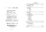
If your outlet is not gronnded,
install a copper wire, at least
14 gauge (2mm-'), from the outlet box, as shown in Figure
3B, to a metal cold \vatt'r pipe list. ground clamp on pipe.
IMPORTANT:
The cold \\atcr pipe you use as a ground
nltlst have metal continuity
to electrical ground, if contimv
ity is interrupted
by plastic, rubber, or other electrical
insulaturs; such as hoses, littings, washers or gaskets (including
water meter or pump),
a metal bypass must be used. Any
electrically
insulated connector
should be jumped (as shown
in Figure 3C), with a length of No. 4 wire clamped securely
at both ends.
Pump
Model
HP
Minimum Watt
Rating of Generator
390.305001
1/2
2800
390.304692
1/3
4500
390,304790
1/3
3400
390,305790
1/2
4200
Outlet
IBex
MAINTENANCE
I_k CAUTION ]Make
before
nent.
i
to service
or remove
is unplugged
any
3. Inlet screen
objects.
Clamp
Pump
in oil. No additional
should
be kept
clean
and free of all foreign
Attempting
to disassemble
motor
will void the
warranty.
1. Disconnect
power cord from electrical outlet before working on ptnnp. Tbe volute bottom may be removed to replace impeller or clean pump of mud or debris.
Meter
670 0!94
2.
Figure 3C
Remove
Replace
screws from volute bottom and clean
the gasket/O-Ring
if it is damaged.
To Reassemble:
Thermal
Overload
Attach
Protection
This pump motor has a built-in automatic
thermal overload
protector.
If the motor overheats,
the protector
wiU open
and cut off power to the motor before the heat damages
it
internally.
The overload
will reset automatically
and the
pump will restart after the pump cools down below the danger point.
_DO
motor
motor
could
when
NOT attempt
to work
lubri-
Cleaning
NOTICE:
Metal Water
Pipe
Automatic
compo-
2. IMPORTANT:
Disassembly
of the motor assembly
will
void the warranty. It might also cause internal leakage and
damage to the unit. If repairs are required,
return the
pump to the dealer from whom it was purchased.
6690194
No. 4
Wire
attempting
that the pump
1. The motor in the unit is sealed
cation is necessary.
Bare copper wire to
cold water pipe.
Figure 3B
certain
on the pump
or
if the overload
seems
to have tripped.
The
may restart
without
warning
at any time. You
be injured
and the pump
damaged
if it starts
you are working
on it.
DO NOT attempt to repair a non-operational
sump
Take it to Sears for service by a qualified technician.
pump.
5
volute
bottom
to volute
top with screws.
impeller.
SERVICE
/ SPECIFICATIONS
General
TEATHERED
I AWARNINGIRisk
of electric
pump
always
disconnect
and remove
pump
electric
I. If pump
a. Check
shock.
When
servicing
power
to electrical
cord from outlet.
outlet
does not opcnltc:
for loosc
plug at electric
outlet.
b. Check for blown fuses or tripped
fuse box/circuit
breaker box.
c. Be sure nothing
float switch.
interl_zrcs
with
circuit
action
breakers
at
of automatic
d. lfa, b, and c above check OK, plug in a light that you
know works. If it lights, take your pump to Sears for
service. If it doesn't light, the electrical circuit is faulty;
consult a licensed electrician.
SWITCH
REPLACEMENT
NOTICE: Teathcred float must bc able to swing through its
complete arc without interference from sidewall of sun]p.
l_hunl_ing or ally otiacr ohjcct.
I Rcn]<)ve
ptln)p power cord fiom s\\itch
plug
2. I{cmove tether clamp screw and slide cord from clamp.
3. Insert new cord in tether clamp. Put the clamp at the
same distance from the float that it was on the old switch.
4. Tighten tether clamp screw.
5. Check sump pump operation by filling sump with water
and observing operation through one complete cycle.
[_ikWARNING ]Failure to check installation
with water
in sump can lead to improper operation,
pump failure and flooding.
premature
2. Pump starts, but blows fuses/trips circuit breakers:
After disconnecting power to pump, remove the screen
and shield from the bottom of the pump and make sure
that the impeller turns freely. Remove any debris obstructing impeller. If pump still does not operate correctly, return it to your nearest Sears Service Department
for repairs.
3. Pump runs, but does not empty sump:
a. Clean pump intake screen.
b. Water may be entering sump faster than the pump can
discharge it.
c. Be sure vertical distance from pump discharge outlet
to discharge pipe outlet does not exceed maximum
vertical pumping distance shown in "Specifications,"
below.
d. Be sure discharge pipe is not plugged or frozen.
SPECIFICATIONS
Dimensions in inches (mm)
Width
Height
Stock
Number
HP
Maximum
Amps
Length
30469
1/3
13.0
9" (229)
6-1/2" (165)
3050
1/2
7.6
9" (229)
6-1/2" (165)
30479
1/3
9.8
9-3/4" (248)
30579
112
12.0
9-3/4" (248)
GPM(L/rain.)at VerticalPumpingDistancein Feet(M)
5' (1.6)
10' (3)
15' (4.6) ! 20' (6.1)
25' (7.6)
11-1/2" (292)
50(189)
41 (155)
28(106)
3 (11.4)
-
11-1/2" (292)
61 (231)
56(212)
50(189)
46(174)
43(163)
7-5/16" (186) 11-1/2" (292)
48(182)
39(148)
29(110)
16(61)
-
7-5/16" (186) 11-1/2" (292)
62 (235)
53 (200)
46 (174)
38 (144)
26 (98)
SERVICE
VERTICAL
SWITCH
Model
VERTICAL
REPLACEMENT
SWITCH
Models
390.304692
REPLACEMENT
390.30479
and 390.30579
_y
(_
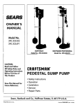
Mount
lhe
bracket
onlo the
switch
Brackel
Br_ckel
housing
Mounting
Inset Drawing
Housing
(_
Siip the
[_o_l
onto
rod
the
•
Screw
the rod
stop onto the
end o[ the lod
I
Screws
Switch
_
(AI
•
Rod
FlOat
_
!
•
i
Float
"
Rod ,_
(_
Inset1 Stop
the rod assembly
._
up into the switch
(B)_
housin 9 (A) and _ock
into place with the
pin (5_). See the inset
drawing
(_
Attach
the swilch
to
the pump as shown
to Bottom of
Pump
CAUTION
housing;
j Make
otherwise
To check switch
plete cycle after
[_- WARNINGj
Plug
only,
pump
sure
pin holds
pump
operation,
installation.
Risk
will
run
of electrical
and switch
into
not
float
shut
housing;
pump
through
shock.
Can
a grounded
A CAUTION 1 Make
rod in switch
off.
burn
electrical
one
com-
or kill.
outlet
To check
switch
plete cycle after
I_" WARNINGI
Plug
on/y
pump
o
sure
otherwise
of
switch
electrical
into
holds
will
operation,
installation.
Risk
and
pin
pump
run
not
float
shut
pump
shock.
a grounded
rod
in switch
off.
through
Can
burn
electrical
one
or
com-
kill
outlet
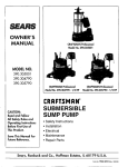
REPAIR PARTS
Model
390.305001
Model390.304692
Model
390.304790
/ 390.305790
9
9
1
9A
9B
10
10
11
1
11
i
ltA
l
11A
J
12
-14 B
14A
|
14A -
t5
REPAIR
Key
Part
Description
No.
1
Switch
2
3
Mounting
Screw
Bracket
Cord Clip
Float Rod
Float Retainer Pin
Float
6
7
8
9
9A
9B
10
11
11A
Retainer Strap
Float Stop
Screw
Power Cord
Cord Connector
O-Ring
Motor Housing
Upper Volute
Screws
12
13
14A
14B
Impeller
Volute Gasket
Base Plate
Lower Volute
15
t6
390.305001
PS117-144P
3A
4
4A
5
U30-955PS
CC0030-13
LIST
390.304692
PS28-17
PS30-3
PS28-18
PS28-17
PS28-17
PS28-18
PS19-21
RP0005248
U30-539SS
PW117-281-TSU
PS17-46P
U9-370
PS28-18
PS19-21
RP0005248
U30-539SS
PWt 17-237-TSU
PS17-46P
U9-370
PS5-26P
PS20-21
PS5-29P
PS20-21
PS1-34P
U30-966SS (7 Req.)
U30-967SS
U78-130P
PS1-34P
U30-966SS (7 Req.)
U30-967SS
U78-130P
PSl17-53-TSU
PS1-28P
PS1-29P
U30-912PS (4 Req.)
R P00O0911A
U30-934ZP
(8 Req.)
390.305790
PSt7-85
PSt9-2OSS
U30-955PS(2
PS117-54-TSU
U30-920SS (3 Req,)
PS5-22P
PS20-19
PS3-29P
390.304790
PSt7-66
PSt9-18SS
U3O-955PS (3 Reg.)
RP0005248
Cap Screws
Cap Screw
1-1/4x1-1/2" Reducer Bushing
Quantity ONE unless otherwise
• Not illustrated.
PARTS
Req.)
PS17-85
PS19-20SS
U30-955PS (2 Req.)
PS4-17P
U30-934ZP
noted ().
•* If motor fails, replace entire pump.
8
(8 Req.)
I:RRFTSMRW
OWNER'S
MANUAL
SUBMERSIBLE
SUMP PUMP
Model No.
390.305001
390.304692
390.304790
Forthe repairor replacementpartsyou need
Call7 am - 7 pro, 7 claysa week
1-800-366-PART
(1-800-366-7278)
390.305790
Forin-homemajorbrandrepairservice
Call24 hoursa day,7 days a week
1-800-4-REPAIR
(1-800-473-7247)
The model number of
your Submersible Sump
Pump will be found on a
plate attached to the side
of the motor.
When requesting service
or ordering parts, always
give the following
information:
• Product Type
• Model Number
• Part Number
• Part Description
Forthe locationof a
SearsRepairServiceCenterin yourarea
Call24 hoursa day, 7 days a week
1-800-488-1222
For informationon purchasinga Sears
MaintenanceAgreementor to inquire
aboutan existingAgreement
call 9 am - 5 pro, Monday-Saturday
A
1-800-827-6655
SEARS
America'sRepair Specialists
Sears, Roebuck and Co., Hoffman Estates, IL 60179
U.S.A.