1
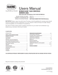
President
GAS FIRED VENTED ROOM HEATERS
MODEL 520AN
For Natural Gas
MODEL 520AP
For L P G (Propane) Gas
WARNING: If the information in this manual is
not followed exactly, a fire or explosion may result
causing property damage, personal injury or loss of
life.
− Do not store or use gasoline or other flammable
vapors and liquids in the vicinity of this or any
other appliance.
− WHAT TO DO IF YOU SMELL GAS
• Do not try to light any appliance.
• Do not touch any electrical switch; do not use
any phone in your building.
• Immediately call your gas supplier from a
neighbor’s phone. Follow the gas supplier’s
instructions.
• If you cannot reach your gas supplier, call the
fire department.
− Installation and service must be performed by a
qualified installer, service agency or the gas
supplier
This appliance is a domestic room heater. It must not
be used for any other purpose such as drying clothes etc.
INSTALLATION & OPERATION MANUAL
Please read this manual before installing and operating your heater.
Please keep this manual for future reference.
(Vous pourrez vous procurer un manuel en langue Française chez votre concessionaire)
600A671/02
CONTENTS
Page
Safety information
Installation instructions
• General
• Rates
• Orifice data
• Clearances
• Floor requirements
• Draft hood
• Venting
• Optional accessories
• Possible installations
• Contents of packs
• Assembling outer cast-iron case
• Heater preparation
• Ignition spark check
• Gas supply connection
• Log installation
• Operation check
• System pressure check
• Venting check
• Aeration adjustment
• Completion of assembly
• Final checks
Operating procedure
• Lighting if igniter fails
• Safety warnings
• Lighting instructions
Cleaning
Periodic checks
Calling for service
Servicing information for qualified engineer
• Burner tube removal
• Electrode removal
• Pilot & cross lighting burner removal
• Pilot jet removal
• Regulator removal
• Control valve & ignition generator removal
• Thermocouple removal
3
4
4
4
4
5
5
5
5
5
5
6
6
7
8
8
9
10
10
10
11
11
13
14
14
15
16
17
17
17
18
18
18
18
18
19
19
19
2
SAFETY INFORMATION
Due to high temperatures, the appliance should be
located out of traffic and away from furniture and
draperies.
Keep the appliance area well clear and free from
combustible materials, gasoline and other flammable
vapors and liquids.
Children and adults should be alerted to the hazards of
high surface temperatures and should stay away to
avoid burns or clothing ignition.
If any changes are made to the room construction in
the vicinity of the appliance after installation (e.g.
additional mantle etc.) make sure that the changes
conform to the installation requirements in this manual.
Young children should be carefully supervised when
they are in the same room as the appliance.
Never attempt to burn paper or any other material in
the appliance.
Clothing or other flammable material should not be
placed on or near the appliance.
Keep the base of the appliance below the ashlip and
the area between the outer case and the wall clear to
prevent obstruction of air flow to the appliance.
The glass window unit must be put back in place prior
to operating the appliance if it has been removed for
servicing or cleaning.
This appliance must be properly connected to a
venting system. The appliance is equipped with a vent
safety shutoff system designed to protect against
improper venting. Operating when not connected to a
properly installed and maintained venting system or
tampering with the shutoff system can result in carbon
monoxide (CO) poisoning and possible death.
The venting system should be checked periodically.
Recent trends in home improvement and new tighter
construction techniques have contributed to problems
with venting. If you suspect that your appliance is not
venting properly, do not operate. Seek expert advice.
Never operate with broken or damaged window glass.
This appliance should be installed and repaired by a
qualified service person.
The appliance should be inspected before use and at
least annually by a professional service person. More
frequent cleaning may be required due to excessive
lint from carpeting, bedding material, etc. It is
imperative that control compartments, burners and
circulating air passageways of the appliance are kept
clean.
Do not use this appliance if any part has been under
water. Immediately call a qualified service technician to
inspect the appliance and to replace any part of the
control system and any gas control which has been
under water.
Keep curtains, clothing, furniture and other flammable
materials at least 36ins (900mm) from the front and top
of the appliance
NOTE
When operating your new room heater for the first time, some vapors may be released which may cause a slight odor and could possibly set off any
smoke detection alarms in the immediate vicinity. These vapors are quite normal on new appliances. They are totally harmless and will disappear after a
few hours use.
3
Rates (Btu/h)
Natural Gas
INSTALLATION INSTRUCTIONS
1. GENERAL
Altitude
Max.
Min.
(Ft)*
Input
0-2000
20,000
7,700
2000-4500
17,800
7,000
Output
0-2000
15,000
5,300
2000-4500
12,500
4,900
* Altitudes above 2000ft require conversion kit 525HACK
Propane
Altitude (Ft)
Max.
Min.
Input
0-4500
17,000
8,750
Output
12,750
Orifice Data
For verification only. Do not attempt to drill or otherwise
modify appliance output.
Gas
Type
No of
Dia (ins)
holes
This appliance is certified by International Approval
Services for use in Canada and the USA.
The installation must conform with local codes or, in the
absence of local codes, with the current
CAN/CGA-B149 installation code in Canada or the current
National Fuel Gas Code, ANSI Z223.1 in the USA. Only
qualified licensed or trained personnel should install the
appliance.
The appliance rating plate is on the inner face of the back
panel at the left side.
Burner Type: Aerated front and rear simplex tubes with
combined pilot and cross lighting burner.
Gas Connection: A 3/8" N.P.T elbow connector is provided
for connection to the appliance inlet pipe located at the
center back.
Natural
Pilot
Front
Rear
Propane
Pilot
Front
Rear
AMAL 40
Cat 18300
Cat 99230
Cat 96010
Cat 960110
Cat 960100
1
7
0.022
0.025
7
0.022
1
0.0094
1
0.035
1
0.034
Mantles: For a mantle not more than 7” deep - minimum clearance is 6” above extreme top surface of heater. For mantle of greater depth
add 1/2” extra clearance for each extra 1” of mantle depth.
Fig.1 Dimensions & clearances
4
1.1 CLEARANCES:
Make sure that the minimum clearances to combustible materials
are maintained during installation including adequate space for
the proper operation and servicing of the heater. The minimum
clearances from the heater to combustible materials are shown in
figure 1. The combustion air opening below the ashlip assembly
and the clearance at the sides of the case rear must not be
obstructed.
ensure that no sags or dips are allowed to occur where the liner
connects to the heater (figure 2).
2. Free standing with connection to an approved chimney or vent
maintaining the clearances shown in figure 1.
3. As a zero clearance installation fitted with the optional
#401CVK Concealed Venting Kit.
This kit allows the heater to be installed with a type B metal vent
concealed behind a wall or partition and/or in a chase. The
venting kit is designed for a 4” round flue. The kit is shown in
figure 3.
Clearances to combustible materials are: Outside edges of
framing plate = 0”. From any part of the flue adapter box
= 1”. Clearances from the connecting elbow are
determined by local codes or, in the absence of local codes,
with the current CAN/CGA1-B149 Installation Code in
Canada or the current National Fuel Gas Code, ANSI
Z223.1 in the USA
1.2 FLOOR:
Do not place the heater on carpeting, vinyl or other soft surfaced
floor coverings. Install only on hard surfaced materials.
It is recommended for aesthetic considerations and ease of
maintenance that the heater is installed on a hearth finished with
brick, ceramic tile, marble etc. Raising the hearth slightly will help
to minimize dust and lint accumulation under the unit. The
recommended minimum hearth size is 32” wide x 15” deep.
If however, the heater is installed directly on flooring of
combustible material other than wood, it must be installed on a
metal or wood panel extending the full width and depth of the
heater.
1.3 DRAFT HOOD:
This heater has a draft hood built into its back and draws its air
from either side. It must not be altered or obstructed. The draft
hood must be in the same atmospheric pressure zone as the
combustion air inlet to the heater.
1.4 VENTING:
This heater is a vented appliance and must be connected to a
chimney or flue in accordance with the national and local codes.
For added safety, this heater is equipped with a vent sensor system
which will react to incorrect venting by shutting down the gas
supply. The thermally activated sensor switch is located within
the draft hood to detect either a blocked or disconnected vent.
Certain backdraft conditions may also activate the switch.
1.5 OPTIONAL ACCESSORIES:
The following kit can be used with this appliance:#401CVK Concealed Vent Kit required for use with a new zero
clearance type installation. It allows the heater to be installed with
type B metal vent concealed behind a wall or partition and/or in a
chase.
Full installation and operating instructions are supplied with the
kit.
For full details above this kit, contact your dealer.
Fig. 2 Flexible chimney liner
1.6 POSSIBLE INSTALLATIONS
This appliance can be installed:
1. As a retrofit
a. To an existing masonry fireplace and chimney
b. To an existing factory built zero clearance type fireplace with a
factory built chimney.
The fireplace must be built in accordance with the national, state,
provincial or territorial building code recognized by the authority
having jurisdiction, or the National Fire Protection Association
code in the USA
Any flue damper must be removed or locked open.
The chimney must be swept and both chimney and fireplace
checked for soundness before installation of the heater.
If local codes dictate or if condensation is a problem, a flue liner
must be installed. Use a flue liner that is approved by the
enforcing authority and that is installed in accordance with the
manufacturers instructions. If a flexible liner system is used,
Fig. 3 Concealed vent kit installation
5
2. UNPACKING THE HEATER AND CASE
3. ASSEMBLING THE CAST IRON OUTER CASE
CONTENTS OF THE PACKAGES
Please read these instructions fully before attempting to install the
Outer Case for the first time.
Box 1 of 3 (Heat engine)
The carton contains the following:1 Heater assembly
3 Ceramic logs (packed in the heater)
1 Flue collar
1 Flue collar extension
1 Wall spacer
1 Smoke channel (Venting check)
1 Control knob
1 Control shaft
8 Threadcutting screws for flue collar & smoke channel
2 Plastic caps for foot screws
1 Caution/Instruction position label
2 Nuts and lockwashers for wall spacer
2 Flat washers and machine screws for
arched lintel fixing
THE OUTER CASE COMPONENTS ARE HEAVY
The cast-iron outer case supplied with President is a high quality
casting weighing around 120lbs in total, therefore it is supplied as
individual components that are easily assembled together to form a
whole. The weight of the heaviest piece is 28 lb. If you have any
doubt of your ability to easily assemble these components, you
should ask someone to assist.
Remove the outer case components from Boxes 2 and 3, identify
each part, and check for transit damage. Note there are two Side
Panels (left and right), a lower ashlip/front feet assembly, an
Arched Lintel component, a Door, and a Top Plate. See exploded
diagram below (Figure 4).
The outer case components comprise:2 Left and right side panels with leveling feet.
1 Ashlip/front feet assembly
1 Arched lintel assembly
1 Door assembly
1 Top plate
Identify the two Side Panels. Take the left panel and observe the
leveling feet. The leveling feet are precision-machined to a high
finish to avoid scratching the hearth.
Offer up the panel to the vertical plane of the fireplace back panel
and observe that the panel sits level on the hearth leaving no
discernible vertical gap against the fireplace. Adjust the leveling
feet to eliminate any such gap.
Place to one side. Similarly adjust the right hand panel for level.
Place to one side.
Box 2 of 3 (Outer case)
2 Side Panels (outer case)
1 Door assembly (outer case)
Box 3 of 3 (Outer case)
1 Top Plate (outer case)
1 Arched lintel (outer case)
1 Ashlip/front feet assembly (outer case).
Remove the contents carefully to prevent damage. Some items
may be contained in
the packaging
fitments - Examine
carefully before
discarding. Check
that all the items are
present and
undamaged.
Note the weight of
the component on
the outside of each
box.
Fig. 4 Outer case components
6
Fig. 5 Ashlip & feet assembly
Take the
ashlip/front feet
assembly and
observe the
attachment
arrangements
(see Figure 5) at
the rear of the
assembly, and
place on the
floor, in front of
the fireplace.
Stand the heater
upright.
Remove the window
unit assembly by
detaching the
knurled screws at the
sides near the top.
Lift the window unit
up to clear locations
at the bottom and
Fig. 7 Window removal
place carefully aside
(see fig. 7).
Carefully remove the
ceramic logs from
inside the firebox and
place to one side.
Fit the flue collar to
the back of the heater
using four thread
cutting screws
provided. (See fig. 8).
Fit the smoke
channel (for venting
check) to the back of
the heater using four
thread cutting screws
provided. (See fig. 8).
Fit the top rear wall
Fig. 8 Flue collar, smoke channel & wall
spacer provided by
spacer installation
attaching it to the 2
bolts visible on the
rear of the heater convection hood above the flue collar. (Lock
washer and nuts provided in pack). (See fig. 8).
If installing to #401CVK Concealed Vent Kit
When installing the Valor President to the #401 Concealed Vent
Kit, the vent collar does not penetrate sufficiently into the flue
adaptor box to ensure good extraction of the combustion
products. The collar extension assures good extraction.
If the Valor President is not being installed to the #401
Concealed vent kit don’t use the extension.
Fitting the extension (See figure 8A):
• Make the extension into a coil small enough to fit inside the
vent collar.
• Push the coiled extension right into the vent collar as far as it
will go.
• Release the extension so that the coil expands against the
inner diameter of the collar.
• Seal the joint between the collar and extension all round with
Take the left side panel
and remove the assembly
bolt using a 7/16th
wrench or socket.
Attach the side panel to
the ashlip assembly. It
may assist to slacken the
ashlip bracket retaining
bolt during this process.
Replace side bolt and
tighten both bolts. Take
the remaining side panel
and repeat the assembly
process. Lifting carefully,
place the entire Side
Panel/Ashlip assembly
Fig.6 Assembled sides and ashlip
onto the hearth.Check
the Side Panel/Ashlip
assembly is level and that there is not a discernible vertical gap
against the Fireplace, adjust the side panel leveling feet to
eliminate any such gap. Once leveling is complete adjust the
ashlip support legs so that they just touch the hearth panel
(Figure 6). Carefully lift the Side Panel/Ashlip assembly off the
hearth to allow preparation and connection of the heat engine.
4. PREPARATION
Turn the appliance on its side with the control valve facing
upwards.
Insert the control shaft into the guide tube (see figure 6A).
Turn the control shaft to align the Phillips head screw with the
flat on the valve shaft.
Slacken the Philips head screw and locate the control shaft boss
over the valve shaft.
Leave the Phillips head
screw slack until the
casting is fitted.
the sealing tape.
Fig. 6A
Fig. 8A Extension collar
7
5. CHECK IGNITION SPARK
7. CONNECT THE GAS SUPPLY
To gain access to the appliance connection point, the center panel
in the firebox floor must be removed by unscrewing four screws
and lifting
it clear (see
figure 10).
Route the
supply gas
line to the
heater
connection
point.
The
appliance is
supplied
with a
3/8”NPT
elbow
Fig. 10 Firebox floor panel removal
connector
for connection to the supply pipe.
Use only new black iron or steel pipes or copper tubing it
acceptable - check local codes.
Note: In USA copper tubing must be internally tinned for
protection against sulfur compounds.
Unions in gas lines should be of ground joint type.
The gas supply line must be sized and installed to provide a supply
of gas sufficient to meet the maximum demand of the appliance
without undue loss of pressure.
Sealant used must be resistant to the action of all gas constituents
including L.P gas. Sealant should be applied lightly to male
threads to ensure excess sealant does not enter gas lines.
The supply line should include a manual shut-off valve and
union in the line for safety and to allow the appliance to be
disconnected for servicing.
Pressure test the supply line. The appliance and its individual shut
off valve must be disconnected from the gas supply piping system
during any pressure testing of that system at test pressures in
excess of 1/2psig (3.5kPa).
The appliance must be isolated from the gas supply piping system
by closing its individual manual shut off valve during any pressure
testing of the gas supply piping system at test pressures equal to or
less than 1/2psig (3.5kPa).
All piping and connections must be tested for leaks after
installation or servicing.
All leaks must be correct immediately.
When testing for leaks:(a) Make sure that the appliance control knob is at the OFF
position.
(b) Open the manual shut-off valve
(c) Test for leaks by applying a liquid detergent or soap solution
to all joints. Bubbles forming indicate a gas leak. NEVER USE
AN OPEN FLAME TO CHECK FOR LEAKS
(d) Correct any leak detected immediately. Refit the firebox floor
panel when testing results are satisfactory.
The pilot
electrode is
situated at the
right side of the
firebox above the
rear port of the
pilot and cross
lighting burner see figure 9
Check that there
is an ignition
spark at the pilot
port.
Fit the control
knob over the
control valve.
To initiate a spark
Fig. 9 Pilot ignition system
depress the
control knob.
While keeping it depressed, turn counter clockwise until the click
of the spark igniter is reached.
If there is no spark produced during several attempts, check that
the electrode lead is properly connected to the electrode and that
the spark gap is correct. Replace parts, if necessary, as described in
the relevant servicing sections of this manual.
6. INSTALL THE FIRE
To prevent hearth damage, two plastic caps are included in the
accessory pack. Fit these caps over the heads of the leveling screws
in the front feet.
Level the fire by slackening the two lock nuts and turning the
leveling screws in the front feet up or down as required while they
bear on the hearth. When the fire is level and square to the wall,
retighten the lock nuts.
8
8. LOG INSTALLATION
8.1 Place the rear log (the log with only one short stub)
in the retaining cradle behind the rear burner tube with
its back against the firebox back wall (fig. 11). The short
stub should be at the top right of the log. Center the
log so that the gap to the firebox walls is the same at
each side.
8.2 Place the front log on the retaining cradles between
the rear and front burner tubes (fig. 12). Center the log
so that the gap to the firebox walls is the same at each
side.
8.3 Place the cross log in position (see fig. 13). The
front of this log is indicated by the letter “F” embossed
on its underside. Make sure that the front of the log is
seated inside the follow in the front log and is not raised
in front of it.
8.4 Replace the window unit. Locate its bottom edge in
the support channels at the firebox sides. Refit the
knurled screws at the sides near the top.
Fig. 11 Rear log location
Fig. 12 Front log location
Fig. 13 Cross log location
9
9. CHECK APPLIANCE OPERATION
Depress the control knob. Turn counter clockwise until resistance
is felt just before the piezo-electric ignition is activated. Keep the
knob depressed for a few seconds to purge air from the gas lines.
When it is judged that the air has been purged keep the knob
depressed and turn to the ignition position. A spark should be
produced which should ignite the pilot and cross lighting burner.
When ignition has been achieved, keep the control knob depressed
for approximately five seconds to allow the thermocouple probe to
warm up then release it. It the burner does not remain alight,
ensure that the air has been purged.
Check that the burners are correctly alight at the four settings on
the control valve as shown in the following table:Control knob Burner appearance
position
Pilot & cross lighting burner only
For altitude level above 2000Ft on Natural Gas only:
Max
Min
Supply 10.5
5.0
upstream of
heater
regulator
Manifold 3.5
3.1
Downstream
of heater
regulator at
high setting
The burner manifold pressure is controlled by a built-in non
adjustable regulator. The manifold pressure should be checked at
the pressure test point which is located immediately downstream
of the regulator (i.e. located above the regulator). The pressure
check should be carried out with the fire alight and the control
knob at the full on position. The pressure setting should be
within the limits shown in the table.
If the pressure reading at this test point is incorrect but the supply
system pressure is correct when measured at the test point
upstream of the regulator, then the regulator is faulty and should
be replaced. After checking the pressure, turn off the fire, remove
the pressure gauge and replace the pressure test sealing screw. Test
the sealing screw for gas soundness.
Pilot & cross lighting burner on.
Front burner on low
Pilot & cross lighting burner on.
Front burner on low.
Rear burner on high
Pilot & cross lighting burner on.
Front burner on high.
Rear burner on high
11. CHECK FOR CORRECT VENTING
A CHECK FOR CORRECT VENTING OF COMBUSTION
PRODUCTS MUST BE MADE BEFORE THE INSTALLED
HEATER IS LEFT WITH THE CUSTOMER. THE TEST
SHOULD BE MADE IN THE FOLLOWING MANNER
Light the heater and set the control to the full on position.
After the appliance has been alight for five minutes place a lighted
smoke match or taper at the right side of the case level with the
opening of the smoke channel - see figure 14.
The installation is satisfactory if the majority of the smoke is
drawn into
the draft
diverter.
If the vent is
blocked or
has strong
reverse flow,
the thermally
actuated
switch
mounted in
the draft
diverter
opening will
automatically
shut off the
gas supply
within about
five minutes. Fig.14 Venting check
If most of the
smoke is not drawn in, leave for about ten minutes and then try
again.
If the majority of the smoke is still not drawn into the draft
diverter, turn the heater off and check cause of lack of draft, if
necessary get expert advice.
Turn off after checking. To turn off, Push the control partially
in, turn clockwise and release the knob. If any resistance is
experienced at the ignition position, release the knob before
turning to the off position.
Note: If the fire is turned off while hot, wait three minutes before
relighting.
10. CHECK SYSTEM PRESSURES
For input adjustment, the gas supply pressure to the appliance
inlet must be between the figures in the table:Test Tapping
Point
Supply upstream of
heater
regulator
ManifoldDownstream
of heater
regulator at
high setting
Pressures (in w.c.)
Natural Gas
Max
Min
10.5
5.0
4.2
3.8
Propane
Max
14.0
Min
11.0
9.7
9.3
10
12. AERATION ADJUSTMENT (See Fig. 15)
Natural gas appliances have adjustable shutters to control primary
aeration on both rear and front burner tubes.
Propane appliances have an adjustable shutter on the front burner
tube only. The
air holes are at
the right side of
the tubes. The
appliances are
supplied set at
maximum
aeration. For
the majority of
installations no
adjustment will
be necessary.
However, in a
few instances,
performance
may be
improved by
reducing the
aeration by
sliding the
shutters to the
left or right.
Evaluate the
aeration only
after the heater
has warmed up
(approximately
Fig. 15 Aeration shutters
15 minutes).
Decreasing
aeration will cause the flames to appear more yellow or Orange
revealing less glow in the logs. Too little aeration may result in
black carbon forming and dropping into the firebox.
Take the cast-iron
Arched Lintel
component and
observe the fixing
attachments on the
rear, and towards
the inside top of the
Side Panels (Figure
17).
13. COMPLETION OF THE CAST-IRON OUTER CASE
ASSEMBLY
Lifting carefully, place the entire Side Panel/Ashlip assembly onto
the hearth in
front of the
Heater
centralizing the
shallow cut-out
in the cast-iron
ashlip against the
sheet metal
uprights of the
Heater firebox
(Figure 16).
point and drop the
lower hinge pin into
the hole provided.
Holding the door
using one hand,
carefully lift up the
right hand side of
the arched lintel
component (Figure
19) and offer up the
door to a position
below the top hinge,
which is mounted
on the arched lintel.
Allow the hinge pin
Fig. 19 Door hinge attachment
in the arched lintel
to locate into the
door hinge, by carefully lowering the arched lintel into position.
The door should hinge freely. Close the door.
Offer up the arched
lintel component to
the side panels in
turn, and locate
onto the
attachments in the
side panel (Figure
Fig. 17 Arched lintel attachment points
18).
The sheet metal
component attached to
the rear of the arched
lintel should sit on top
of the horizontal front
section of the heater
convection hood.
Ensure the Arched
Lintel is a good fit,
adjusting the location of
the side panels slightly if
necessary.
Take the cast-iron door,
and observe the hinges
on the right hand side,
looking from the front.
Offer up the door to the
Fig. 18 Arched lintel installation
ashlip assembly hinge
Fig. 16 Outer case & firebox relationship
11
The Outer Case assembly can now be attached to the Heater.
Locate the bolts and washers supplied, and fasten the Arched
Lintel to the top surface of the Heat Engine as shown in Figure
20. Ensure the sheet metal components fit closely together, or
adjust the Arched Lintel attachment points for height as shown in
Figure 21 until they do so.
Observe the correct operation of the door. Using the handle, lift
the door slightly so that it
is released from the
“catch”. It should swing
freely, and open/close
easily.
If further adjustment to
the door alignment is
required, loosen the
fastening bolts(Figure 20)
and adjust the door within
its ”frame” by moving the
outer case slightly - left to
right - until the correct
door operation is achieved.
Refasten all bolts.
Remove the gas control
knob from the extension
rod.
Take the Top Plate, open
the hinged gas control
access panel, and locate the
top plate onto the two
Fig. 20 Arched lintel to heater
attachment
Side Panels and
Arched Lintel,
taking care to insert
the control rod
through the guide
hole in the gas
control well (Figure
22). Refit the
control knob over
the control valve
extension rod. Push
firmly on.
Control Knob Adjustment
Due to
variations in
casting
dimensions the
height of the
shaft linkage
between the gas
control valve
and the control
knob can vary.
If the shaft is
too long, it
could prevent
the cast iron
Fig. 22A Control rod location
knob access door
from closing
properly. If the shaft is too short, it could prevent the pilot from
lighting because the gas valve is not depressing fully.
If the shaft protrudes less than 7/8”, first turn the control knob to
a position between the High and Medium setting. This will give
access to the Phillips head coupling screw through the hole found
at the rear of the heater in the mounting bracket which holds the
gas valve (see figure 22B). Adjust the coupling until 7/8” of shaft
protrudes through the hole in the top of the cast iron case.
Tighten the
screw.
If the shaft
protrudes
more than
7/8” at its
lowest
Fig 22B Control rod fastening
position ,
Tighten the
coupling screw at the lowest shaft position. Make a note of how
much the shaft protrudes in excess of 7/8”. Remove the cast iron
case top and lift the rest of the cast iron case away from the
heater. Screw out the leveling feet on the cast iron sides by the
amount of excess shaft protrusion. (This will raise the cast iron
case top so that the shaft only protrudes by 7/8”). Replace the cast
iron case and top.
IMPORTANT: Tighten the screw firmly against the flat
face of the “D” on the control knob spindle
Fig. 21 Arched lintel height adjustment
Fig. 22 Control rod location
12
MAKE FINAL CHECKS AND INSTRUCT OWNER
Make sure that the logs have not been dislodged when fitting the
case.
Fit the Caution & Direction label to the right hand side of the
case in the position shown in Figure 23.
Recheck the operation of
the fire on all control
positions.
Instruct the owner how
to correctly operate the
heater and especially
point out the following:The heater has a pilot. To
light the pilot, the control
knob must be depressed
and turned to the
position.
The pilot flame can be
viewed to check that it is
alight. Show the owner
where to view the pilot.
Point out the illustration
showing how to view the
pilot.
Explain the full lighting
Fig. 23 Caution label position
and control position
sequence and how to
turn off. It must be explained that the gas control access panel
must be kept open while the heater is in operation. Advise that the
fire can be lit with a long match or taper if necessary.
Advise that the window will require cleaning periodically both
outside and inside as described in the instructions. Explain how to
remove and replace the window unit and logs for cleaning etc.
Stress that cleaning and opening of the door should only be
carried out when the heater is cold. Advise that the heater may
give off a slight odor while new. This is quite normal and will
disappear after a short period of use.
Advise that the bright metal firebox interior will color with use
and that this is quite normal. Emphasize that if the glass panel is
broken or damaged, the heater should be turned off and not used
until the window unit is refitted with an authorized replacement.
13
14. OPERATING PROCEDURE
Full lighting instructions are given on the next pages.
For your safety this heater is fitted with a Flame Supervision
Device which will shut off the gas supply if for any reason the
pilot flames go out. This device incorporates a fixed probe which
senses heat from the pilot flame. If the probe is cool the device will
prevent any gas flow unless the control knob is held down. When
first turned on, the decorative flames will appear predominantly
blue. After approximately 15 minutes these flames will turn
yellow.
After approximately 3 hours use at the high control setting the
fuel pieces will show areas of charcoal gray color as would real
burning logs.
Control knob Burner appearance
position
Pilot & cross lighting burner only
In the unlikely event of failure of the ignition spark, the heater
can be lit by a long burning match as follows:
Open the cast door fully to gain access to the heater. Light the
match and insert through the opening in the black bar near the
bottom right corner of the window. Insert the match so that
about 1” is inside the black bar (see figure 24).
Open the hinged gas control access panel.
Depress the control knob and turn to the
position. Keep it
depressed while lighting the pilot and for a few seconds afterwards.
The pilot flame can be seen by looking through the gap at the
front right corner of the logs (see figure 25). When the pilot is
satisfactorily alight, close the door.
Pilot & cross lighting burner on.
Front burner on low
Pilot & cross lighting burner on.
Front burner on low.
Rear burner on high
Pilot & cross lighting burner on.
Front burner on high.
Rear burner on high
14.1. Lighting if ignition spark fails
Fig.24 Match lighting
Fig. 25 Pilot flame position
14
FOR YOUR SAFETY READ BEFORE LIGHTING
WARNING: If you do not follow these instructions exactly, a fire or explosion may result
causing property damage, personal injury or loss of life.
A. This appliance has a pilot which must be lighted by hand. When lighting the pilot, follow these
instructions exactly.
B. BEFORE LIGHTING smell all round the appliance area for gas. Be sure to smell next to the
floor because some gas is heavier than air and will settle on the floor.
WHAT TO DO IF YOU SMELL GAS
l
Do not try to light any appliance.
l Do not touch any electric switch; do not use any phone in your building.
l
Immediately call your gas supplier from a neighbor’s phone. Follow the gas supplier’s
instructions.
l
If you cannot reach your gas supplier, call the fire department.
C. Use only your hand to push in or turn the gas control knob. Never use tools. If the knob will
not push in or turn by hand, don’t try to repair it, call a qualified service technician. Force or
attempted repair may result in a fire or explosion.
D. Do not use this appliance if any part has been under water. Immediately call a qualified
service technician to inspect the appliance and to replace any part of the control system and
any gas control which has been under water.
15
LIGHTING INSTRUCTIONS
STOP! Read the safety information on previous page.
1. Open the hinged access panel at rear right of case top
2. Turn the control knob on right side of heater
clockwise to “OFF” position (marked
l ).
NOTE: Knob cannot be turned to off unless knob is pushed in partially. Do not force.
3. Wait five (5) minutes to clear out any gas. Then smell for gas, including near the floor. If you
smell gas, STOP! Follow “B” in the safety information on previous page. If you don’t smell gas, go
to the next step.
4. Find the pilot. It is at the right side of the firebox.
5. Push in and turn the control knob
counterclockwise until resistance is felt
just before the ignition
position marked
6. Keep pushed in for a few seconds to allow gas to flow then, keeping the knob depressed , turn to
ignition to light pilot. Hold knob in for a further 5 seconds then release. The knob should pop
back up. Pilot should remain lit. If it goes out repeat steps 2 through 6. If pilot does not light at
all during a few attempts, try lighting with a long match as described below.
• If knob does not pop up when released, stop and immediately call your service technician or gas
supplier.
• If the pilot lights but will not stay alight after several tries, turn the gas control knob off and call
your service technician or gas supplier.
7. When pilot is lit, partially depress the knob and select burner setting (the knob should be
depressed slightly when changing settings).
For maximum efficiency, turn to high setting (marked ) for the first 10 minutes to warm the
chimney or flue.
• Do not operate between the setting positions.
• Do not close the access panel while heater is in operation
Match lighting: Open main door and insert a long match to the pilot while the control knob is
pushed in and at the ignition position.
TO TURN OFF GAS TO APPLIANCE
1. Push in control knob partially and turn
clockwise to off (marked l ). Do not force.
16
15. CLEANING
All cleaning should be carried out when the heater is cold. Normally,
the heater should only need dusting. Any stains on the glass can be
removed with a non abrasive cleaner.
Abrasive cleaners should never be used on the glass.
15.1 Cleaning the inside of the window:
Open the case door fully. Remove the window unit by detaching the
knurled screws at sides near the top. Lift the window unit assembly up
to clear the locations at the bottom - see fig 7. In installation section of
this manual.
Be careful not to disturb the logs when removing the window. If they
are disturbed, refit them as described in the log installation section of
this manual.
Clean the window carefully by wiping with a soft cloth using a
suitable non abrasive cleaner in accordance with the makers
instructions. Replace the window unit. Locate its bottom edge in the
support channels at the firebox sides. Refit the two knurled screws and
tighten. Replace the window surround.
17. CALLING FOR SERVICING
For owner
If you require any attention to your appliance, contact your supplier
quoting the model number. It is helpful if the appliance serial number
is also quoted. This will be found near the back of the case at the
bottom right side.
The servicing information on the following pages is for use
only for a qualified service engineer.
16 PERIODIC CHECKS
The venting system should be examined by a qualified agency
regularly. We suggest annually. The flow of combustion and
ventilation air must not be obstructed. A periodic visual check of the
pilot and burner flames should be made (see figs. 26 & 27)
Fig. 26 Burner flames
Fig. 27 Pilot flame
17
18 SERVICING INFORMATION - (For qualified service
engineers only)
The repair parts are shown on the separate repair parts leaflet. Please
always quote Part Number and description with requests for spares.
TURN OFF THE GAS AND MAKE SURE THAT THE
APPLIANCE IS COOL BEFORE COMMENCING ANY
SERVICING. ALWAYS TEST FOR GAS SOUNDNESS AND
CORRECT VENTING OF COMBUSTION PRODUCTS AFTER
REFITTING THE APPLIANCE.
Methods of removal of the window unit and control knob are
described in the installation and cleaning sections of this manual.
18.4 TO REMOVE THE PILOT & CROSS LIGHTING
BURNER
1.Open the cast door remove the window unit assembly and logs.
2.To gain clear access to the pilot burner screw, detach the right hand
front log support by removing two screws - see figure 28.
3.Remove the pilot and cross lighting burner by unscrewing the two
screws fixing it to the bracket at the right side of the firebox - see
figure 28.
4.Refit in the reverse order.
18.1 TO REMOVE THE REAR BURNER TUBE
1. Open the cast door remove the window unit assembly and logs.
2. Unscrew the two screws securing the burner tube to the left side of
the firebox. Lift the burner tube clear.
3. Refit in the reverse order. When refitting make sure that the burner
tube is properly located over the injector carrier at the right side.
18.2 TO REMOVE THE FRONT BURNER TUBE
1. Open the cast door remove the window unit and logs.
2. Remove the screw securing the firebox front cross rail at the left side
and decorative baffle.
3. Slacken the screw securing the cross rail and decorative baffle at the
right side and swing the rail upwards at the left side to give access to
the burner tube screws.
4. Unscrew the two screws securing the burner tube to the left side of
the firebox. Lift the burner tube clear.
5. Refit in the reverse order. When refitting make sure that the burner
tube is properly located over the injector carrier at the right side.
18.3 TO REMOVE THE ELECTRODE
1.Disassemble the outer case by reversing the procedures outline earlier
in the installation manual until the condition shown in Figure 16 is
reached. Carefully lift the sides and ashlip assembly forward and away
from the heater.
2.Though not essential for access to the electrode, it is recommended
that the window unit and logs are removed so that the electrode tip
position can be checked when replaced.
3.Remove the two screws securing the electrode unit to the bulkhead
panel outside the right side of the firebox. Pull the electrode with lead
attached clear.
4.Disconnect the lead from the electrode.
5.Refit in the reverse order.
Fig. 28 Firebox internal fixings
18.5 TO REMOVE THE PILOT JET
1. Remove the two screws securing the firebox front cross rail and
decorative baffle. Lift rail and baffle clear.
2. Remove the pilot and cross lighting burner - see section 19.4
3. Disconnect the pilot pipe at the jet end and spring clear of the
carrier.
4. Remove the pilot jet and carrier from the bracket.
5. Refit in the reverse order. Test for leaks
18
18.6 TO REMOVE THE PRESSURE REGULATOR
1.Remove the outer case see section 18.3.
18.8 TO REMOVE THE IGNITION SPARK GENERATOR
1.Remove the control valve and spark generator as 18.7 above.
2.Make sure that the valve is in the off position.
3.Remove the circlip holding the spark generator to the valve. Remove
the generator.
4.Refit in the reverse order. Seal with pipe sealant.
18.9 TO REMOVE THE THERMOCOUPLE
1.Remove the outer case (see section 18.3)
2.Remove the window unit assembly
3.Undo the thermocouple from the interrupter block at the bottom of
the control valve (note that the vent sensor wires will then be loose).
Undo the nut securing the thermocouple probe to the manifold panel
and withdraw the thermocouple.
4.Remove the screw securing the firebox front cross rail and decorative
baffle at the right side.
5.Slacken the screw securing the cross rail and decorative baffle at the
left side and swing the rail down at the right side to give access to the
nut securing the thermocouple probe.
6.Refit in the reverse order. When reconnecting the thermocouple nut
to the control valve, make sure that the vent sensor wires are properly
located. Initially screw the thermocouple nut until finger tight, then
finally tighten a further quarter turn with a wrench.
Fig. 29 Regulator removal points
2.Disconnect the pipes from each end of the regulator and spring them
free from the test tapping tee pieces.
3.Remove the two regulator bracket screws and lift the regulator unit
free.
4.Fit new regulator assembly in the reverse order. When replacing
make sure that the regulator flow direction is correct. The regulator
has a flow direction arrow on its back face. Seal with pipe sealant.
5. Note that if fitting a new regulator, the regulator fixing holes are
unthreaded. Tapping screws are used.
18.7 TO REMOVE THE CONTROL VALVE AND
IGNITION SPARK GENERATOR
1.Remove the outer case (see section 18.3)
2.Disconnect the heater from the venting system and pull forward to
gain access to the rear of the control valve.
3.Disconnect the electrode lead
4.Disconnect the valve extension rod by removing the split pin just
above the valve spindle and lifting rod upwards (see fig.30)
Fig. 30 Valve removal points
5.Disconnect the four pipes from the control valve.
6.Remove the control valve securing nut.
7.Disconnect the thermocouple and vent sensor wires from the
interrupter block.
8.Transfer the extension rod/valve spindle connector to the
replacement valve.
9.Refit in reverse order. Test for leaks.
19
Manufactured by
HEATING
BIRMINGHAM, ENGLAND
Because our policy is one of constant development and improvement, details may vary slightly from those given in this publication.
© Valor Ltd. 1996, 2000
20