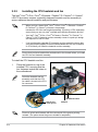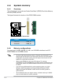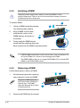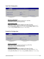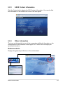
1
Motherboard P5LD2-C/IPAT E3609 First Edition January 2008 Copyright © 2008 ASUSTeK COMPUTER INC. All Rights Reserved. No part of this manual, including the products and software described in it, may be reproduced, transmitted, transcribed, stored in a retrieval system, or translated into any language in any form or by any means, except documentation kept by the purchaser for backup purposes, without the express written permission of ASUSTeK COMPUTER INC. (“ASUS”). Product warranty or service will not be extended if: (1) the product is repaired, modified or altered, unless such repair, modification of alteration is authorized in writing by ASUS; or (2) the serial number of the product is defaced or missing. ASUS PROVIDES THIS MANUAL “AS IS” WITHOUT WARRANTY OF ANY KIND, EITHER EXPRESS OR IMPLIED, INCLUDING BUT NOT LIMITED TO THE IMPLIED WARRANTIES OR CONDITIONS OF MERCHANTABILITY OR FITNESS FOR A PARTICULAR PURPOSE. IN NO EVENT SHALL ASUS, ITS DIRECTORS, OFFICERS, EMPLOYEES OR AGENTS BE LIABLE FOR ANY INDIRECT, SPECIAL, INCIDENTAL, OR CONSEQUENTIAL DAMAGES (INCLUDING DAMAGES FOR LOSS OF PROFITS, LOSS OF BUSINESS, LOSS OF USE OR DATA, INTERRUPTION OF BUSINESS AND THE LIKE), EVEN IF ASUS HAS BEEN ADVISED OF THE POSSIBILITY OF SUCH DAMAGES ARISING FROM ANY DEFECT OR ERROR IN THIS MANUAL OR PRODUCT. SPECIFICATIONS AND INFORMATION CONTAINED IN THIS MANUAL ARE FURNISHED FOR INFORMATIONAL USE ONLY, AND ARE SUBJECT TO CHANGE AT ANY TIME WITHOUT NOTICE, AND SHOULD NOT BE CONSTRUED AS A COMMITMENT BY ASUS. ASUS ASSUMES NO RESPONSIBILITY OR LIABILITY FOR ANY ERRORS OR INACCURACIES THAT MAY APPEAR IN THIS MANUAL, INCLUDING THE PRODUCTS AND SOFTWARE DESCRIBED IN IT. Products and corporate names appearing in this manual may or may not be registered trademarks or copyrights of their respective companies, and are used only for identification or explanation and to the owners’ benefit, without intent to infringe. ii Contents Notices.......................................................................................................... vi Safety information...................................................................................... vii About this guide........................................................................................ viii P5LD2-C/IPAT specifications summary...................................................... x Chapter 1: Product introduction 1.1 Welcome!....................................................................................... 1-1 1.3 Special features............................................................................. 1-2 1.2 Package contents.......................................................................... 1-1 Product highlights............................................................................ 1-2 Chapter 2: 2.1 2.2 Motherboard overview.................................................................. 2-2 2.2.1 Placement direction......................................................... 2-2 2.2.3 Motherboard layout.......................................................... 2-3 2.2.2 2.3 2.2.4 Installing the CPU............................................................ 2-5 2.3.3 Uninstalling the CPU heatsink and fan.......................... 2-10 2.4.1 Overview........................................................................ 2-12 2.4.3 Installing a DIMM........................................................... 2-16 2.4.4 Memory configurations................................................... 2-12 Removing a DIMM......................................................... 2-16 Expansion slots........................................................................... 2-17 2.5.1 Installing an expansion card.......................................... 2-17 2.5.3 Interrupt assignments.................................................... 2-18 2.5.4 2.5.5 2.7 Installing the CPU heatsink and fan................................. 2-8 System memory.......................................................................... 2-12 2.5.2 2.6 Layout contents................................................................ 2-4 2.3.1 2.4.2 2.5 Screw holes..................................................................... 2-2 Central Processing Unit (CPU).................................................... 2-5 2.3.2 2.4 Hardware information Before you proceed...................................................................... 2-1 2.5.6 Configuring an expansion card...................................... 2-17 PCI slots......................................................................... 2-19 PCI Express x16 slot...................................................... 2-19 PCI Express x1 slot........................................................ 2-19 Jumpers....................................................................................... 2-20 Connectors.................................................................................. 2-22 iii Contents 2.7.1 2.7.2 Chapter 3: 3.1 3.2 3.2.1 BIOS setup Creating a bootable floppy disk........................................ 4-1 4.1.3 AFUWIN utility.................................................................. 4-5 AFUDOS utility................................................................. 4-2 BIOS setup program..................................................................... 4-6 4.2.1 BIOS menu screen........................................................... 4-7 4.2.3 Navigation keys................................................................ 4-7 4.2.4 4.2.5 4.2.6 4.2.7 4.2.8 4.2.9 Menu bar.......................................................................... 4-7 Menu items...................................................................... 4-8 Sub-menu items............................................................... 4-8 Configuration fields.......................................................... 4-8 Pop-up window................................................................ 4-8 Scroll bar.......................................................................... 4-8 General help.................................................................... 4-8 Main menu..................................................................................... 4-9 4.3.1 BIOS Information............................................................. 4-9 4.3.3 System Date ................................................................... 4-9 4.3.2 4.3.4 Memory Information......................................................... 4-9 System Time ................................................................... 4-9 Advanced menu.......................................................................... 4-10 4.4.1 Pxe Boot Option............................................................. 4-10 4.4.3 CPU Configuration......................................................... 4-12 4.4.2 4.4.4 4.4.5 4.4.6 iv Using the dual function power switch............................... 3-2 4.1.1 4.2.2 4.4 Using the OS shut down function..................................... 3-2 Managing and updating your BIOS............................................. 4-1 4.1.2 4.3 Powering up Powering off the computer........................................................... 3-2 Chapter 4: 4.2 Internal connectors........................................................ 2-23 Starting up for the first time......................................................... 3-1 3.2.2 4.1 Rear panel connectors................................................... 2-22 ACPI Settings..................................................................4-11 IDE Configuration........................................................... 4-13 On Board LAN................................................................ 4-14 Other Power On Device................................................. 4-15 Contents 4.4.7 4.5 4.4.8 4.7 4.8 4.5.1 North Bridge................................................................... 4-20 4.5.3 Legacy USB Configuration............................................. 4-22 5.2 2.6.1 2.6.2 2.7.1 2.7.2 Setup Prompt Timeout .................................................. 4-23 Setup Administrator Password....................................... 4-24 User Password............................................................... 4-25 Exit menu..................................................................................... 4-26 Software support Installing an operating system.................................................... 5-1 Support CD information............................................................... 5-1 5.2.1 Running the support CD.................................................. 5-1 5.2.3 ASUS Contact information............................................... 5-3 5.2.4 Appendix: A.2 Quiet Boot ..................................................................... 4-23 Security menu............................................................................. 4-24 5.2.2 A.1 South Bridge.................................................................. 4-21 Boot menu................................................................................... 4-23 Chapter 5: 5.1 PCI Subsystem Settings................................................ 4-18 Chipset menu.............................................................................. 4-20 4.5.2 4.6 Super IO Configuration.................................................. 4-16 Drivers menu.................................................................... 5-2 Other information............................................................. 5-3 CPU features Enhanced Intel SpeedStep® Technology (EIST).........................A-1 A.1.1 A.1.2 System requirements.......................................................A-1 Using the EIST.................................................................A-1 Intel® Hyper-Threading Technology............................................A-2 Using the Hyper-Threading Technology . .......................................A-2 Notices Federal Communications Commission Statement This device complies with Part 15 of the FCC Rules. Operation is subject to the following two conditions: • This device may not cause harmful interference, and • This device must accept any interference received including interference that may cause undesired operation. This equipment has been tested and found to comply with the limits for a Class B digital device, pursuant to Part 15 of the FCC Rules. These limits are designed to provide reasonable protection against harmful interference in a residential installation. This equipment generates, uses and can radiate radio frequency energy and, if not installed and used in accordance with manufacturer’s instructions, may cause harmful interference to radio communications. However, there is no guarantee that interference will not occur in a particular installation. If this equipment does cause harmful interference to radio or television reception, which can be determined by turning the equipment off and on, the user is encouraged to try to correct the interference by one or more of the following measures: • Reorient or relocate the receiving antenna. • Increase the separation between the equipment and receiver. • Connect the equipment to an outlet on a circuit different from that to which the receiver is connected. • Consult the dealer or an experienced radio/TV technician for help. The use of shielded cables for connection of the monitor to the graphics card is required to assure compliance with FCC regulations. Changes or modifications to this unit not expressly approved by the party responsible for compliance could void the user’s authority to operate this equipment. Canadian Department of Communications Statement This digital apparatus does not exceed the Class B limits for radio noise emissions from digital apparatus set out in the Radio Interference Regulations of the Canadian Department of Communications. This class B digital apparatus complies with Canadian ICES-003. vi Safety information Electrical safety • To prevent electrical shock hazard, disconnect the power cable from the electrical outlet before relocating the system. • When adding or removing devices to or from the system, ensure that the power cables for the devices are unplugged before the signal cables are connected. If possible, disconnect all power cables from the existing system before you add a device. • Before connecting or removing signal cables from the motherboard, ensure that all power cables are unplugged. • Seek professional assistance before using an adpater or extension cord. These devices could interrupt the grounding circuit. • Make sure that your power supply is set to the correct voltage in your area. If you are not sure about the voltage of the electrical outlet you are using, contact your local power company. • If the power supply is broken, do not try to fix it by yourself. Contact a qualified service technician or your retailer. Operation safety • Before installing the motherboard and adding devices on it, carefully read all the manuals that came with the package. • Before using the product, make sure all cables are correctly connected and the power cables are not damaged. If you detect any damage, contact your dealer immediately. • To avoid short circuits, keep paper clips, screws, and staples away from connectors, slots, sockets and circuitry. • Avoid dust, humidity, and temperature extremes. Do not place the product in any area where it may become wet. • Place the product on a stable surface. • If you encounter technical problems with the product, contact a qualified service technician or your retailer. The symbol of the crossed out wheeled bin indicates that the product (electrical, electronic equipment, Mercury-containing button cell battery) should not be placed in municipal waste. Check local regulations for disposal of electronic products. vii About this guide This user guide contains the information you need when installing and configuring the motherboard. How this guide is organized This guide contains the following parts: • Chapter 1: Product introduction This chapter describes the features of the motherboard and the new technology it supports. • Chapter 2: Hardware information This chapter lists the hardware setup procedures that you have to perform when installing system components. It includes description of the switches, jumpers, and connectors on the motherboard. • Chapter 3: Powering up This chapter describes the power up sequence, the vocal POST messages, and ways of shutting down the system. • Chapter 4: BIOS setup This chapter tells how to change system settings through the BIOS Setup menus. Detailed descriptions of the BIOS parameters are also provided. • Chapter 5: Software support This chapter describes the contents of the support CD that comes with the motherboard package. • Appendix: CPU features The Appendix describes the CPU features that the motherboard supports. Where to find more information Refer to the following sources for additional information and for product and software updates. viii 1. ASUS websites The ASUS website provides updated information on ASUS hardware and software products. Refer to the ASUS contact information. 2. Optional documentation Your product package may include optional documentation, such as warranty flyers, that may have been added by your dealer. These documents are not part of the standard package. Conventions used in this guide To make sure that you perform certain tasks properly, take note of the following symbols used throughout this manual. DANGER/WARNING: Information to prevent injury to yourself when trying to complete a task. CAUTION: Information to prevent damage to the components when trying to complete a task. IMPORTANT: Instructions that you MUST follow to complete a task. NOTE: Tips and additional information to help you complete a task. Typography Bold text Indicates a menu or an item to select. Italics Used to emphasize a word or a phrase. <Key> Keys enclosed in the less-than and greater-than sign means that you must press the enclosed key. Example: <Enter> means that you must press the Enter or Return key. <Key1>+<Key2>+<Key3> If you must press two or more keys simultaneously, the key names are linked with a plus sign (+). Example: <Ctrl>+<Alt>+<D> Command Means that you must type the command exactly as shown, then supply the required item or value enclosed in brackets. Example: At the DOS prompt, type the command line: afudos /i[filename] afudos /iP5LD2CIPAT.ROM ix P5LD2-C/IPAT specifications summary CPU LGA775 socket for Intel® CoreTM 2 Duo / CoreTM 2 Extreme / Pentium® D / Pentium® 4 / Celeron® processors Supports next generation 45nm multi-core CPU Intel® Hyper-Threading Technology ready Supports Enhanced Intel SpeedStep® Technology (EIST) Chipset Northbridge: Intel® MCH 945GC Southbridge: Intel® ICH7 Front Side Bus 1066 / 800 / 533 MHz Memory 2 x 240-pin DIMM sockets support unbuffered non-ECC DDR2 533 / 667 memory modules Supports up to 4 GB system memory Expansion slots 1 x PCIe x16 slot for discrete graphic card 1 x PCIe x1 slot 5 x PCI slots Storage Intel® ICH7 South Bridge supports: - 1 x Ultra DMA 100 / 66 / 33 - 4 x Serial ATA 3Gb/s devices Audio ALC662 6-channel High Definition Audio CODEC Supports Jack-detect, Anti Pop Funtion, Multi-Streaming Compatible with Vista Premium OS LAN RTL 8111C PCIe Gb LAN Rear panel 1 x Parallel port 2 x COM ports 1 x PS/2 keyboard port 1 x PS/2 mouse port 1 x RJ45 4 x USB 2.0/1.1 prots 6-channel Audio I/O ports Internal connectors Azalia High Definition Analog Front Panel Audio connector 1 x Chassis Intrusion 1 x 4-pin internal speaker connector 1 x 24-pin EPS12V power connector 1 x 4-pin ATX 12V power connector 2 x USB connectors for 4 additional USB 2.0 ports 1 x CD audio-in connector 1 x CPU fan connector 1 x Chassis fan connector BIOS features 8 Mb Flash ROM, AMI BIOS, PnP, DMI v2.0, WfM2.0, SMBIOS v2.4, ACPI v3.0 USB Supports up to 8 USB 2.0 ports (4 ports at mid-board, 4 ports at rear panel) (continued on the next page) P5LD2-C/IPAT specifications summary Menageability WOL by PME, WOR by PME, WOR Support CD contents Drivers IPAT Application Accessories 1 x SATA cable 1 x SATA power cable 1 x FDD cable 1 x UltraDMA 100/66 cable 1 x I/O Shield User’s manual Form factor ATX form factor: 12 in x 7.5 in (30.5 cm x 19 cm) *Specifications are subject to change without notice. xi xii This chapter describes the motherboard features and the new technologies it supports. 1 Product introduction Chapter summary 1 1.1 Welcome!....................................................................................... 1-1 1.3 Special features............................................................................. 1-2 1.2 Package contents.......................................................................... 1-1 ASUS P5LD2-C/IPAT 1.1 Welcome! Thank you for buying an ASUS® P5LD2-C/IPAT motherboard! The motherboard delivers a host of new features and latest technologies, making it another standout in the long line of ASUS quality motherboards! Before you start installing the motherboard, and hardware devices on it, check the items in your package with the list below. 1.2 Package contents Check your motherboard package for the following items. Motherboard ASUS P5LD2-C/IPAT motherboard Cables 1 x Floppy disk drive cable 1 x Serial ATA cable 1 x Serial ATA power cable 1 x UltraDMA 100/66 cable Accessories I/O shield Application CDs ASUS motherboard support CD IPAT software CD Documentation User guide If any of the above items is damaged or missing, contact your retailer. ASUS P5LD2-C/IPAT 1- 1.3 Special features Product highlights Latest processor technology The motherboard comes with a 775-pin surface mount Land Grid Array (LGA) socket designed for the Intel® Prescott, Intel® Smithfield, Intel® Cedarmill, Intel® Conroe, Intel® Conroe L or Intel® Presler processor in the 775-land package. The motherboard supports the processors with 1066 / 800 / 533 MHz Front Side Bus (FSB). The motherboard also supports the Intel® Hyper‑Threading Technology and Enhanced Intel® SpeedStep Technology (EIST). See pages 2-5, A-1 and A-2 for details. Intel® Core™2 This motherboard supports the latest Intel® Core™2 processor in the LGA775 package. With the new Intel® Core™ microarchitecture technology and 1066 / 800 / 533 MHz FSB, Intel® Core™2 processor is one of the most powerful and energy efficient CPU in the world. 64-bit CPU support 64-bit computing, the next generation technology to replace current 32-bit architecture, delivers advanced system performance, faster memory access and increased productivity. This motherboard provides excellent compatibility and flexibility by supporting either 64-bit or 32-bit architecture. DDR2 memory support The motherboard supports DDR2 memory that features data transfer rates of 667 / 533 MHz to meet the higher bandwidth requirements of the latest 3D graphics, multimedia, and Internet applications. The dual-channel DDR2 architecture doubles the bandwidth of your system memory to boost system performance, eliminating bottlenecks with peak bandwidths of up to 10.6 GB/s. See page 2-11 for details. 1- Chapter 1: Product introduction High Definition Audio The onboard 6-channel ALC662 High Definition audio CODEC enables high-quality audio which automatically detects peripherals are plugged into the audio I/O jacks. ALC662 also supports Windows® Vista Premium. See pages 2-22 for details. Serial ATA 3.0 Gb/s technology This motherboard supports the next-generation hard drives based on the Serial ATA (SATA) 3Gb/s storage specification, delivering enhanced scalability and doubling the bus bandwidth for high-speed data retrieval and saves. Easily backup photos, videos and other entertainment contents to external devices. See page 2‑25 for details. PCI Express™ interface The motherboard fully supports PCI Express, the latest I/O interconnect technology that speeds up the PCI bus. PCI Express features point‑to‑point serial interconnections between devices and allows higher clockspeeds by carrying data in packets. This high speed interface is software compatible with existing PCI specifications. See page 2-19 for details. USB 2.0 technology The motherboard implements the Universal Serial Bus (USB) 2.0 specification, dramatically increasing the connection speed from the 12 Mbps bandwidth on USB 1.1 to a fast 480 Mbps on USB 2.0. USB 2.0 is backward compatible with USB 1.1. See pages 2-23 and 2-26 for details. Green ASUS The motherboard and its packaging comply with the European Union’s Restriction on the use of Hazardous Substances (RoHS). This is in line with the ASUS vision of creating environment-friendly and recyclable products and packaging to safeguard consumers’ health while minimizing the impact on the environment. ASUS P5LD2-C/IPAT 1- 1- Chapter 1: Product introduction This chapter lists the hardware setup procedures that you have to perform when installing system components. It includes description of the jumpers and connectors on the motherboard. 2 Hardware information Chapter summary 2 2.1 Before you proceed...................................................................... 2-1 2.3 Central Processing Unit (CPU).................................................... 2-5 2.2 2.4 Motherboard overview.................................................................. 2-2 System memory.......................................................................... 2-12 2.5 Expansion slots........................................................................... 2-17 2.7 Connectors.................................................................................. 2-22 2.6 Jumpers....................................................................................... 2-20 ASUS P5LD2-C/IPAT 2.1 Before you proceed Take note of the following precautions before you install motherboard components or change any motherboard settings. • Unplug the power cord from the wall socket before touching any component. • Use a grounded wrist strap or touch a safely grounded object or to a metal object, such as the power supply case, before handling components to avoid damaging them due to static electricity. • Hold components by the edges to avoid touching the ICs on them. • Whenever you uninstall any component, place it on a grounded antistatic pad or in the bag that came with the component. • Before you install or remove any component, ensure that the ATX power supply is switched off or the power cord is detached from the power supply. Failure to do so may cause severe damage to the motherboard, peripherals, and/or components. Onboard LED P5LD2-C/IPAT The motherboard comes with a standby power LED. The green LED lights up to indicate that the system is ON, in sleep mode, or in soft-off mode. This is a reminder that you should shut down the system and unplug the power cable before removing or plugging in any motherboard component. The illustration below shows the location of the onboard LED. SB_PWR ON Standby Power OFF Powered Off P5LD2-C/IPAT Onboard LED ASUS P5LD2-C/IPAT 2- 2.2 Motherboard overview Before you install the motherboard, study the configuration of your chassis to ensure that the motherboard fits into it. Ensure to unplug the power cord before installing or removing the motherboard. Failure to do so can cause you physical injury and damage motherboard components. 2.2.1 Placement direction When installing the motherboard, ensure that you place it into the chassis in the correct orientation. The edge with external ports goes to the rear part of the chassis as indicated in the image below. 2.2.2 Screw holes Place seven (7) screws into the holes indicated by circles to secure the motherboard to the chassis. Place this side towards the rear of the chassis 2- P5LD2-C/IPAT Do not overtighten the screws! Doing so can damage the motherboard. Chapter 2: Hardware information 2.2.3 Motherboard layout 19cm (7.5in) PS/2KBMS T: Mouse B: Keyboard ATX12V COM1 Realtek 8111C CR2032 3V Lithium Cell CMOS Power 30.5cm (12in) PCIEX1_1 EATXPWR RTM876-660 DDR2 DIMM_B1 (64 bit,240-pin module) Intel 945GC AUDIO P5LD2-C/IPAT LAN_USB12 CHA_FAN USB34 CPU_FAN PS2_USBPW1-8 COM2 DDR2 DIMM_A1 (64 bit,240-pin module) PARALLE PORT LGA775 PCIEX16 Super I/O PCI1 PCI2 Intel ICH7 PCI4 8Mb BIOS ALC662 SATA1 SATA2 SATA3 SATA4 PCI5 CD AAFP ASUS P5LD2-C/IPAT PRI_IDE PCI3 CLRTC CHASSIS SPEAKER FLOPPY USB56 USB78 SB_PWR F_PANEL 2- 2.2.4 2- Layout contents Slots Page 1. PCI 2-19 2. PCIe x 16 2-19 3. PCIe x 1 2-19 Jumpers Page 1. Clear RTC RAM (3-pin CLRTC) 2-20 2. USB Device wake-up (3-pin PS2_USBPW1-8) 2-21 Rear panel connectors Page 1. PS/2 mouse port (green) 2-22 2. Parallel port 2-22 3. LAN (RJ-45) port 2-22 4. Line In port (light blue) 2-22 5. Line Out port (green) 2-22 6. Microphone port (pink) 2-22 7. USB 2.0 ports 1 and 2 2-23 8. USB 2.0 ports 3 and 4 2-23 9. Serial port (COM2) 2-23 10. Serial port (COM1) 2-23 11. PS/2 keyboard port (purple) 2-23 Internal connectors Page 1. Floppy disk drive connector (34-1 pin FLOPPY) 2-23 2. ICH7 Primary IDE connector (40-1 pin PRI_IDE) 2-24 3. Optical drive audio connector (4-pin CD) 2-24 4. Serial ATA connectors (7-pin SATA1 [red], SATA2 [red], SATA3 [black], SATA4 [black]) 2-25 5. Front panel audio connector (10-1 pin AAFP) 2-26 6. USB connectors (10-1 pin USB56, USB78) 2-26 7. CPU and Chassis Fan connectors (4-pin CPU_FAN, 3-pin CHA_FAN) 2-27 8. Chassis intrusion connector (4-1 pin CHASSIS) 2-27 9. ATX power connectors (24-pin EATXPWR, 4-pin ATX12V) 2-28 10. Speaker connector (4-pin SPEAKER) 2-28 11. System panel connector (10-1 pin F_PANEL) 2-29 Chapter 2: Hardware information 2.3 Central Processing Unit (CPU) The motherboard comes with a surface mount LGA775 socket designed for the Intel® CoreTM 2 Duo / CoreTM 2 Extreme / Pentium® D / Pentium® 4 / Celeron® processor in the 775-land package • • • 2.3.1 Upon purchase of the motherboard, ensure that the PnP cap is on the socket and the socket contacts are not bent. Contact your retailer immediately if the PnP cap is missing, or if you see any damage to the PnP cap/socket contacts/motherboard components. ASUS will shoulder the cost of repair only if the damage is shipment/transit-related. Keep the cap after installing the motherboard. ASUS will process Return Merchandise Authorization (RMA) requests only if the motherboard comes with the cap on the LGA775 socket. The product warranty does not cover damage to the socket contacts resulting from incorrect CPU installation/removal, or misplacement/loss/ incorrect removal of the PnP cap. Installing the CPU To install a CPU: Locate the CPU socket on the motherboard. P5LD2-C/IPAT 1. P5LD2-C/IPAT CPU Socket 775 Before installing the CPU, ensure that the cam box is facing towards you and the load lever is on your left. ASUS P5LD2-C/IPAT 2- 2. Press the load lever with your thumb (A), then move it to the left (B) until it is released from the retention tab. Retention tab Load lever A PnP cap B This side of the socket box should face you. To prevent damage to the socket pins, do not remove the PnP cap unless you are installing a CPU. 3. Lift the load lever in the direction of the arrow to a 135º angle. 4. Lift the load plate with your thumb and forefinger to a 100º angle (A), then push the PnP cap from the load plate window to remove (B). B A Load plate 5. Position the CPU over the socket, ensuring that the gold triangle is on the bottom-left corner of the socket. The socket alignment key should fit into the CPU notch. Alignment key Gold triangle mark 2- Chapter 2: Hardware information The CPU fits in only one correct orientation. DO NOT force the CPU into the socket to prevent bending the connectors on the socket and damaging the CPU! 6. Close the load plate (A), then push the load lever (B) until it snaps into the retention tab. A B The motherboard supports Intel® CoreTM 2 Duo / CoreTM 2 Extreme / Pentium® D / Pentium® 4 / Celeron® LGA775 processors with the Intel® Enhanced Intel SpeedStep® Technology (EIST) and Hyper-Threading Technology. Refer to the Appendix for more information on these CPU features. ASUS P5LD2-C/IPAT 2- 2.3.2 Installing the CPU heatsink and fan The Intel® CoreTM 2 Duo / CoreTM 2 Extreme / Pentium® D / Pentium® 4 / Celeron® LGA775 processor requires a specially designed heatsink and fan assembly to ensure optimum thermal condition and performance. • When you buy a boxed Intel® CoreTM 2 Duo / CoreTM 2 Extreme / Pentium® D / Pentium® 4 / Celeron® processor, the package includes the CPU fan and heatsink assembly. If you buy a CPU separately, ensure that you use only Intel®‑certified multi‑directional heatsink and fan. • Your Intel® CoreTM 2 Duo / CoreTM 2 Extreme / Pentium® D / Pentium® 4 / Celeron® LGA775 heatsink and fan assembly comes in a push-pin design and requires no tool to install. • If you purchased a separate CPU heatsink and fan assembly, ensure that you have properly applied Thermal Interface Material to the CPU heatsink or CPU before you install the heatsink and fan assembly. Ensure that you have installed the motherboard to the chassis before you install the CPU fan and heatsink assembly. To install the CPU heatsink and fan: 1. Place the heatsink on top of the installed CPU, ensuring that the four fasteners match the holes on the motherboard. Orient the heatsink and fan assembly such that the CPU fan cable is closest to the CPU fan connector. Motherboard hole Narrow end of the groove Fastener Ensure to orient each fastener with the narrow end of the groove pointing outward. (The photo shows the groove shaded for emphasis.) 2- Chapter 2: Hardware information 2. Push down two fasteners at a time in a diagonal sequence to secure the heatsink and fan assembly in place. B A A 3. A B B A B Connect the CPU fan cable to the connector on the motherboard labeled CPU_FAN. P5LD2-C/IPAT CPU_FAN GND CPU FAN PWR CPU FAN IN CPU FAN PWM P5LD2-C/IPAT CPU Fan Connector Do not forget to connect the CPU fan connector! Hardware monitoring errors can occur if you fail to plug this connector. ASUS P5LD2-C/IPAT 2- 2.3.3 Uninstalling the CPU heatsink and fan To uninstall the CPU heatsink and fan: 1. Disconnect the CPU fan cable from the connector on the motherboard. 2. Rotate each fastener counterclockwise. 3. Pull up two fasteners at a time in a diagonal sequence to disengage the heatsink and fan assembly from the motherboard. 4. 2-10 A B B A B A A B Carefully remove the heatsink and fan assembly from the motherboard. Chapter 2: Hardware information 5. Rotate each fastener clockwise to ensure correct orientation when reinstalling. Narrow end of the groove The narrow end of the groove should point outward after resetting. (The photo shows the groove shaded for emphasis.) Refer to the documentation in the boxed or stand-alone CPU fan package for detailed information on CPU fan installation. ASUS P5LD2-C/IPAT 2-11 2.4 System memory 2.4.1 Overview The motherboard comes with two Double Data Rate 2 (DDR2) Dual Inline Memory Modules (DIMM) sockets. 128 Pins P5LD2-C/IPAT 112 Pins DIMM_A1 DIMM_B1 The figure illustrates the location of the DDR2 DIMM sockets: P5LD2-C/IPAT Fan Connectors 2.4.2 Channel Sockets Channel A DIMM_A1 Channel B DIMM_B1 Memory configurations You may install 128 MB, 256 MB, 512 MB , and 1024 MB unbuffered non-ECC DDR2 DIMMs into the DIMM sockets. 2-12 • You may install varying memory sizes in Channel A and Channel B. The system maps the total size of the lower-sized channel for the dual-channel configuration. Any excess memory from the higher-sized channel is then mapped for single-channel operation. • Always install DIMMs with the same CAS latency. For optimum compatibility, it is recommended that you obtain memory modules from the same vendor. Refer to the DDR2 Qualified Vendors List on the next page for details. • If you are using a Windows 32-bit version operating system (e.g. 32-bit Windows, 32-bit Vista) without the Physical Address Extension (PAE) support, the system will allocate a certain amount of memory space for system devices. • This motherboard does not support memory modules made up of 128 Mb chips or double sided x16 memory modules. Chapter 2: Hardware information Qualified Vendors Lists (QVL) DDR2-533 Size Vendor Model CL Brand SS/ DS Component DIMM support A* B* 256MB Kingston KVR533D2N4/256 N/A Elpida SS E5116AF-5C-E • • 512MB Kingston KVR533D2N4/512 N/A Infineon SS HYB18T512800AF3733336550 • • 1G Kingston KVR533D2N4/1G N/A Kingston DS D6408TLRAGL37U • • 256MB Samsung M378T3253FG0-CD5 N/A Samsung SS K4T56083QF-GCD5 • • 512MB Samsung M378T6553BG0-CD5 4 Samsung SS K4T51083QB-GCD5 • • 256MB HY HYMP532U64CP6-C4 AB 4 Hynix SS HY5PS121621CFP-C4 • • 1G HY HYMP512U64CP8-C4 AB 4 Hynix DS HY5PS12821CFP-C4 • • 512MB Micron MT 16HTF6464AG-53EB2 4 Micron DS D9BOM • • 512MB Micron MT 16HTF6464AG-53EB2 4 Micron DS Z9BQT • • 1G Micron MT 16HTF12864AY-53EA1 4 Micron DS D9CRZ • • 512MB Corsair VS512MB533D2 N/A Corsair DS MIII0052532M8CEC • • 512MB Corsair VS512MB533D2 N/A Corsair DS MI110052532M8CEC • • 1G Corsair VS1GB533D2 N/A Corsair DS 64M8CFEGQIB0900718 • • 512MB Elpida EBE51UD8ABFA-5C-E N/A Elpida SS E5108AB-5C-E • • 512MB Kingmax KLBC28F-A8KB4 N/A Kingmax SS KKEA88B4IAK-37 • • 256MB Kingmax KLBB68F-36EP4 N/A Elpida SS E5116AB-5C-E • • 512MB Kingmax KLBC28F-A8EB4 N/A Elpida SS E5108AE-5C-E • • 512MB ADATA M2OAD2G3H3166I1B52 N/A ADATA SS AD29608A8A-37DG20719 • • 2G ADATA M20AD2H3J4170I1B53 N/A ADATA DS AD20908A8A-37DG30721 • • (continued on the next page) ASUS P5LD2-C/IPAT 2-13 Qualified Vendors Lists (QVL) DDR2-667 Size Vendor 256MB Kingston 256MB Model CL Brand SS/ DS Component DIMM support A* B* KVR667D2N5/256 N/A Kingston SS D3216TLSAKL3U • • Kingston KVR667D2N5/256 N/A Infineon SS HYB18T256800AF3SW65 33154 • • 512MB Kingston KVR667D2N5/512 N/A Elpida SS E5108AGBG-6E-E • • 1G Kingston KVR667D2N5/1G N/A Kingston DS D6408TEBGGL3U • • 1G Kingston KVR667D2N5/1G N/A Elpida DS E5108AGBG-6E-E • • 2G Kingston KVR667D2N5/2G N/A Micron DS 7RE22 D9HNL • • 512MB Samsung KR M378T6553CZ0-CE6 N/A Samsung SS K4T51083QC • • 512MB Samsung KR M378T6453FZ0-CE6 N/A Samsung DS K4T56083QF-ZCE6 • • 512MB Samsung M378T6553CZ3-CE6 N/A Samsung SS K4T51083QC-ZCE6 • • 1G Samsung M378T2953CZ3-CE6 N/A Samsung DS K4T51083QC-ZCE6 • • 1G Samsung KR M378T2953CZ0-CE6 N/A Samsung DS K4T51083QC-ZCE6 • • 512MB Qimonda HYS64T64000EU-3S-B2 5 Qimonda SS HYB18T512B00B2F3SFSS28171 • • 1G Qimonda HYS64T128020EU-3S-B2 5 Qimonda DS HYB18T512B00B2F3SFSS28171 • • 2G Qimonda HYS64T256020EU-3S-B 5 Qimonda DS HTB18T1G800BF-3S3VV10907 • • 512MB Corsair VS512MB667D2 N/A Corsair SS 64M8CFEGPS0900647 • • 512MB Corsair VS512MB667D2 N/A Corsair DS MIII0052532M8CEC • • 1G Corsair VS1GB667D2 N/A Corsair DS MID095D62864M8CEC • • 1G Corsair XMS2-5400 4 Corsair DS Heat-Sink Package • • 256MB HY HYMP532U64CP6-Y5 AB 5 Hynix SS HY5PS121621CFP-Y5 • • 512MB HY HYMP564U64AP8-Y4 AA N/A Hynix SS HY5PS12821AFP-Y4 • • 512MB HY HYMP564U64AP8-Y5 AA N/A Hynix SS HY5PS12821AFP-Y5 • • 1G HY HYMP512U64AP8-Y5 AB N/A Hynix DS HY5PS12821AFP-Y5 • • 1G HY HYMP512U64CP8-Y5 AB 5 Hynix DS HY5PS12521CFP-Y5 • • 512MB Kingmax KLCC28F-A8EB5 N/A Elpida SS E5108AE-6E-E • • 512MB Kingmax KLCC28F-A8KB5 N/A Kingmax SS KKEA88B4LAUG-29DX • • 1G Kingmax KLCD48F-A8KB5 N/A Kingmax DS KKEA88B4LAUG-29DX • • 512MB Apacer 78.91092.420 N/A Elpida SS E5108AE-6E-E • • 512MB Apacer AU512E667C5KBGC 5 Apacer SS AM4B5708MIJS7E0627B • • 512MB Apacer AU512E667C5KBGC 5 Apacer SS AM4B5708GQJS7E06332F • • 512MB Apacer 78.91G92.9KC 5 Apacer SS AM4B5708GQJS7E0706F • • 1G Apacer AU01GE667C5KBGC N/A Apacer DS AM4B5708GQJS7E0636B • • 1G Apacer 78.01092.420 5 Elpida DS E5108AE-6E-E • • 1G Apacer AU01GE667C5KBGC 5 Apacer DS AM4B5708MIJS7E0627B • • 512MB ADATA M20EL5G3H3160B1C0Z N/A Elpida SS E5108AE-6E-E • • 512MB ADATA M20AD5G3H3166I1C52 N/A ADATA SS AD29608A8A-3EG20648 • • (continued on the next page) 2-14 Chapter 2: Hardware information Qualified Vendors Lists (QVL) DDR2-667 Size Vendor Model CL Brand SS/ DS Component DIMM support A* B* 512MB ADATA M20AD5G3H3166I1C52 N/A ADATA SS AD29608A8A-3EG20718 • • 1G ADATA M2OAD5G3I4176I1C52 N/A ADATA DS AD29608A8A-3EG20645 • • 2G ADATA M2OAD5H3J4170I1C53 N/A ADATA DS AD20908A8A-3EG 30724 • • 512MB VDATA M2GVD5G3H31A4I1C52 N/A VDATA SS VD29608A8A-3EC20615 • • 512MB VDATA M2YVD5G3H31P4I1C52 N/A VDATA SS VD29608A8A-3EG20627 • • 512MB VDATA M2GVD5G3H166I1C52 N/A VDATA SS VD29608A8A-3EG20637 • • 1G VDATA M2GVD5G3I41P6I1C52 N/A VDATA DS VD29608A8A-3EG20627 • • 1G VDATA M2GVD5G3I41C4I1C52 N/A VDATA DS VD29608A8A-3EC20620 • • 1G VDATA M2GVD5G3I4176I1C52 N/A VDATA DS VD29608A8A-3EG20641 • • 512MB PSC AL6E8E63B-6E1K 5 PSC SS A3R12E3GEF637BLC5N • • 512MB PSC AL6E8E63J-6E1 5 PSC SS A3R12E3JFF717B9A00 • • 1G PSC AL7E8E63B-6E1K 5 PSC DS A3R12E3GEF637BLC5N • • 1G PSC AL7E8E63J-6E1 5 PSC DS A3R12E3JFF717B9A01 • • 1G PSC AL7E8F73C-6E1 5 PSC SS A3R1GE3CFF734MAA0J • • 2G PSC AL8E8F73C-6E1 5 PSC DS A3R1GE3CFF733MAA00 • • 256MB Nanya NT256T64UH4A1FY-3C N/A Nanya SS NT5TU32M16AG-3C • • 512MB Nanya NT512T64U88A1BY-3C N/A Nanya SS NT5TU64M8AE-3C • • 1G Kingtiger E0736001024667 N/A Kingtiger DS KTG667PS6408NST-C6 GDBTX • • 1G ELIXIR M2Y1G64TU8HA2B-3C 5 ELIXIR DS M2TU51280AE-3C717095R28F • • 1G Leadmaax LRMP512U64A8-Y5 N/A Hynix DS HY5PS12821CFP-Y5 C 702AA • • SS - Single-sided / DS - Double - sided DIMM support: • A*: Supports one module inserted into any slot as Single-channel memory configuration. • B*: Supports one pair of modules inserted into both the yellow slots as one pair of Dual-channel memory configuration. Visit the ASUS website for the latest DDR2-667 / 533 MHz QVL. ASUS P5LD2-C/IPAT 2-15 2.4.3 Installing a DIMM Unplug the power supply before adding or removing DIMMs or other system components. Failure to do so can cause severe damage to both the motherboard and the components. 2 To install a DIMM: 1. Unlock a DIMM socket by pressing 2. Align a DIMM on the socket DIMM matches the break on 3. 3 DDR2 DIMM notch the retaining clips outward. such that the notch on the the socket. 1 Firmly insert the DIMM into the socket until the retaining clips snap back in place and the DIMM is properly seated. Unlocked retaining clip 2.4.4 • A DDR2 DIMM is keyed with a notch so that it fits in only one direction. Do not force a DIMM into a socket to avoid damaging the DIMM. • The DDR2 DIMM sockets do not support DDR DIMMs. DO not install DDR DIMMs to the DDR2 DIMM sockets. Removing a DIMM Follow these steps to remove a DIMM. 1. clips outward to unlock the DIMM. Support the DIMM lightly with your fingers when pressing the retaining clips. The DIMM might get damaged when it flips out with extra force. 2. 2-16 2 Simultaneously press the retaining 1 1 DDR2 DIMM notch Remove the DIMM from the socket. Chapter 2: Hardware information 2.5 Expansion slots In the future, you may need to install expansion cards. The following sub‑sections describe the slots and the expansion cards that they support. Ensure to unplug the power cord before adding or removing expansion cards. Failure to do so may cause you physical injury and damage motherboard components. 2.5.1 Installing an expansion card To install an expansion card: 1. 2. 3. 4. 5. 6. Before installing the expansion card, read the documentation that came with it and make the necessary hardware settings for the card. Remove the system unit cover (if your motherboard is already installed in a chassis). Remove the bracket opposite the slot that you intend to use. Keep the screw for later use. Align the card connector with the slot and press firmly until the card is completely seated on the slot. Secure the card to the chassis with the screw you removed earlier. Replace the system cover. 2.5.2 Configuring an expansion card After installing the expansion card, configure the it by adjusting the software settings. 1. 2. 3. Turn on the system and change the necessary BIOS settings, if any. See Chapter 4 for information on BIOS setup. Assign an IRQ to the card. Refer to the tables on the next page. Install the software drivers for the expansion card. When using PCI cards on shared slots, ensure that the drivers support “Share IRQ” or that the cards do not need IRQ assignments. Otherwise, conflicts will arise between the two PCI groups, making the system unstable and the card inoperable. Refer to the table on the next page for details. ASUS P5LD2-C/IPAT 2-17 2.5.3 Interrupt assignments Standard interrupt assignments IRQ Standard Function 1 Keyboard Controller 0 System Timer 2 Re-direct to IRQ#9 3 — 4 Communications Port (COM1)* 5 IRQ holder for PCI steering* 6 Floppy Disk Controller 7 Printer Port (LPT1)* 8 System CMOS/Real Time Clock 9 IRQ holder for PCI steering* 10 IRQ holder for PCI steering* 11 IRQ holder for PCI steering* 12 PS/2 Compatible Mouse Port* 13 Numeric Data Processor 14 Primary IDE Channel * These IRQs are usually available for ISA or PCI devices. IRQ assignments for this motherboard PCI slot 1 PCI slot 2 PCI slot 3 PCIe x16 slot — — — shared shared Onboard USB controller 1 shared Onboard USB controller 2 Onboard USB controller 3 Onboard USB controller 4 Onboard USB 2.0 controller B shared PCIe x1 slot 1 PCIe x1 slot 2 — C — — shared shared — — — — — — — shared — — — — — — shared — — — — — — Onboard LAN controller — shared — — — — — — — — — — — — — G — — — — F — — — shared — E — — — — D — — Onboard IDE port Onboard HD Audio controller 2-18 A — — — — — — — — — — — H — — — — — — — — — — — — — — shared — — — shared — shared — — — — — — — shared — — — — — — — — — Chapter 2: Hardware information 2.5.4 PCI slots The PCI slots support cards such as a LAN card, SCSI card, USB card, and other cards that comply with PCI specifications. The figure shows a LAN card installed on a PCI slot. 2.5.5 PCI Express x16 slot This motherboard supports PCI Express x16 graphic cards that comply with the PCI Express specifications. The following figure shows a graphics card installed on the PCI Express x16 slot. 2.5.6 PCI Express x1 slot This motherboard supports PCI Express x1 network cards, SCSI cards and other cards that comply with the PCI Express specifications. The following figure shows a network card installed on the PCI Express x1 slot. ASUS P5LD2-C/IPAT 2-19 2.6 Jumpers 1. Clear RTC RAM (CLRTC) This jumper allows you to clear the Real Time Clock (RTC) RAM in CMOS. You can clear the CMOS memory of date, time, and system setup parameters by erasing the CMOS RTC RAM data. The onboard button cell battery powers the RAM data in CMOS, which include system setup information such as system passwords. To erase the RTC RAM: 1. Turn OFF the computer and unplug the power cord. 2. Remove the onboard battery. 3. Move the jumper cap from pins 1-2 (default) to pins 2-3. Keep the cap on pins 2-3 for about 5~10 seconds, then move the cap back to pins 1-2. 4. Re-install the battery. 5. Plug the power cord and turn ON the computer. 6. Hold down the <Del> key during the boot process and enter BIOS setup to re-enter data. P5LD2-C/IPAT Except when clearing the RTC RAM, never remove the cap on CLRTC jumper default position. Removing the cap will cause system boot failure! CLRTC 1 2 Normal (Default) 2 3 Clear RTC P5LD2-C/IPAT Clear RTC RAM 2-20 Chapter 2: Hardware information USB device wake-up (3-pin PS2_USBPW1-8) This jumper allows you to wake up the computer from S1 mode (CPU stopped, DRAM refreshed, system running in low power mode) using the connected USB device. Set this jumper to pins 2-3 (+5VSB) to wake up the computer from S3 and S4 modes (no power to CPU, DRAM in slow refresh, power supply in reduced power mode). +5V (Default) 2 3 PS2_USBPW1-8 1 2 P5LD2-C/IPAT 2. +5VSB P5LD2-C/IPAT USB Device Wake Up The total current consumed must NOT exceed the power supply capability (+5VSB) whether under normal condition or in sleep mode. ASUS P5LD2-C/IPAT 2-21 2.7 Connectors 2.7.1 Rear panel connectors 1 2 3 4 5 6 11 1. 2. 3. 10 9 8 7 PS/2 mouse port (green). This port is for a PS/2 mouse. Parallel port. This 25-pin port connects a parallel printer, a scanner, or other devices. LAN (RJ-45) port. This port allows 10/100Mb connection to a Local Area Network (LAN) through a network hub. Refer to the table below for the LAN port LED indications. LAN port LED indications Activity/Link Status Description OFF No link YELLOW Linked BLINKING Data activity 4. 5. 6. Speed LED Status Description OFF 10 Mbps connection ORANGE 100 Mbps connection GREEN 1 Gbps connection ACT/LINK LED SPEED LED LAN port Line In port (light blue). This port connects a tape, CD, DVD player, or other audio sources. Line Out port (lime). This port connects a headphone or a speaker. In 4channel, and 6-channel configuration, the function of this port becomes Front Speaker Out. Microphone port (pink). This port connects a microphone. Refer to the audio configuration table on next page for the function of the audio ports in 2, 4, or 6-channel configuration. 2-22 Chapter 2: Hardware information Audio 2, 4, or 6-channel configuration Port 7. 8. 9. Headset 2-speaker 4-speaker 6-speaker Light Blue Line In Surround Out Surround Out Lime Line Out Front Speaker Out Front Speaker Out Pink Mic In Mic In Center/Bass USB 2.0 ports 1 and 2. These two 4-pin Universal Serial Bus (USB) ports are available for connecting USB 2.0/1.1 devices. USB 2.0 ports 3 and 4. These two 4-pin Universal Serial Bus (USB) ports are available for connecting USB 2.0/1.1 devices. Serial port (COM2). This port connects a modem, or other devices that conform with serial specification. 10. Serial port (COM1). This port connects a modem, or other devices that conform with serial specification. 11. PS/2 keyboard port (purple). This port is for a PS/2 keyboard. 2.7.2 1. Internal connectors Floppy disk drive connector (34-1 pin FLOPPY) This connector is for the provided floppy disk drive (FDD) signal cable. Insert one end of the cable to this connector, then connect the other end to the signal connector at the back of the floppy disk drive. P5LD2-C/IPAT Pin 5 on the connector is removed to prevent incorrect cable connection when using a FDD cable with a covered Pin 5. FLOPPY PIN 1 NOTE: Orient the red markings on the floppy ribbon cable to PIN 1. P5LD2-C/IPAT Floppy Disk Drive Connector ASUS P5LD2-C/IPAT 2-23 ICH7 Primary IDE connector (40-1 pin PRI_IDE) This connector is for an Ultra DMA 100/66/33 signal cable. The Ultra DMA 100/66/33 signal cable has three connectors: a blue connector for the primary IDE connector on the motherboard, a black connector for an Ultra DMA 100/66/33 IDE slave device (optical drive/hard disk drive), and a gray connector for an Ultra DMA 100/66/33 IDE master device (hard disk drive). If you install two hard disk drives, you must configure the second drive as a slave device by setting its jumper accordingly. Refer to the hard disk documentation for the jumper settings. • Pin 20 on the IDE connector is removed to match the covered hole on the Ultra DMA cable connector. This prevents incorrect insertion when you connect the IDE cable. • Use the 80-conductor IDE cable for Ultra DMA 100/66/33 IDE devices. PRI_IDE P5LD2-C/IPAT 2. P5LD2-C/IPAT IDE Connector 3. Optical drive audio connector (4-pin CD) This connector is for the 4-pin audio cable that connects to the audio connector at the back of the optical drive. Right Audio Channel Ground Ground Left Audio Channel P5LD2-C/IPAT CD (black) P5LD2-C/IPAT Internal Audio Connector 2-24 Chapter 2: Hardware information SATA1 SATA2 GND RSATA_RXN1 RSATA_RXP1 GND RSATA_TXN1 RSATA_TXP1 GND GND RSATA_RXN2 RSATA_RXP2 GND RSATA_TXN2 RSATA_TXP2 GND Serial ATA connectors (7-pin SATA1 [red], SATA2 [red], SATA3 [black], SATA4 [black]) These connectors are for the Serial ATA signal cables for Serial ATA hard disk drives. SATA3 SATA4 GND RSATA_RXN4 RSATA_RXP4 GND RSATA_TXN4 RSATA_TXP4 GND GND RSATA_RXN3 RSATA_RXP3 GND RSATA_TXN3 RSATA_TXP3 GND P5LD2-C/IPAT 4. P5LD2-C/IPAT SATA Connectors • • You must install Windows® 2000 Service Pack 4 or the Windows® XP Service Pack 1 before using Serial ATA hard disk drives. When using the connectors in Standard IDE mode, connect the primary (boot) hard disk drive to the SATA1 or SATA2 connector. Refer to the table below for the recommended SATA hard disk drive connections. Serial ATA hard disk drive connection Connector Color Setting Use SATA1/SATA2 Red Master Boot disk SATA3/SATA4 Black Slave Data disk ASUS P5LD2-C/IPAT 2-25 5. Front panel audio connector (10-1 pin AAFP) This connector is for a chassis-mounted front panel audio I/O module that supports either HD Audio or legacy AC’97 audio standard. AAFP NC AGND NC NC Legacy AC’97 compliant definition MIC2 MICPWR Line out_R NC Line out_L SENSE2_RETUR GND PRESENSE# SENSE1_RETUR PORT1L PORT1R PORT2R SEBSE_SEND PORT2L P5LD2-C/IPAT HD-audio-compliant pin definition P5LD2-C/IPAT Front Panel Audio Connector We recommend that you connect a high-definition front panel audio module to this connector to avail the motherboard high‑definition audio capability. USB+5V USB_P5USB_P5+ GND 1 USB+5V USB_P8USB_P8+ GND NC USB78 1 USB+5V USB_P7USB_P7+ GND USB56 USB+5V USB_P6USB_P6+ GND NC USB port connectors (10-1 pin USB56, USB78) These connectors are for USB 2.0 ports. Connect the optional USB module cable to any of these connectors, then install the module to a slot opening at the back of the system chassis. These USB connectors comply with USB 2.0 specification that supports up to 480 Mbps connection speed. P5LD2-C/IPAT 6. P5LD2-C/IPAT USB 2.0 Connectors The USB cable is purchased separately. 2-26 Chapter 2: Hardware information 7. CPU and chassis fan connectors (4-pin CPU_FAN, 3-pin CHA_FAN) The fan connectors support cooling fans of 350 mA ~ 2000 mA (24 W max.) or a total of 1 A ~ 3.48 A (41.76 W max.) at +12V. Connect the fan cables to the fan connectors on the motherboard, making sure that the black wire of each cable matches the ground pin of the connector. Do not forget to connect the fan cables to the fan connectors. Insufficient air flow inside the system may damage the motherboard components. These are not jumpers! Do not place jumper caps on the fan connectors! CPU_FAN P5LD2-C/IPAT GND CPU FAN PWR CPU FAN IN CPU FAN PWM CHA_FAN GND +12V Rotation P5LD2-C/IPAT Fan Connectors Only the CPU_FAN connector support the ASUS Q‑Fan feature. 8. Chassis intrusion connector (4-1 pin CHASSIS) This connector is for a chassis-mounted intrusion detection sensor or switch. Connect one end of the chassis intrusion sensor or switch cable to this connector. The chassis intrusion sensor or switch sends a high-level signal to this connector when a chassis component is removed or replaced. The signal is then generated as a chassis intrusion event. Chassis Signal GND CHASSIS +5VSB_MB P5LD2-C/IPAT By default, the pins labeled “Chassis Signal” and “GND” are shorted with a jumper cap. Remove the jumper caps only when you intend to use the chassis intrusion detection feature. (Default) P5LD2-C/IPAT Intrusion Connector ASUS P5LD2-C/IPAT 2-27 9. ATX power connectors (24-pin EATXPW, 4-pin ATX12V) These connectors are for ATX power supply plugs. The power supply plugs are designed to fit these connectors in only one orientation. Find the proper orientation and push down firmly until the connectors completely fit. • Use of an ATX 12 V Specification 2.0 -compliant power supply unit (PSU) that provides a minimum power of 350 W is recommended for a fullyconfigured system. • Do not forget to connect the 4-pin ATX +12 V power plug; otherwise, the system will not boot up. • Use of a PSU with a higher power output is recommended when configuring a system with more power consuming devices. The system may become unstable or may not boot up if the power is inadequate. EATXPWR ATX12V +12V DC GND +3 Volts +12 Volts +12 Volts +5V Standby Power OK Ground +5 Volts Ground +5 Volts Ground +3 Volts +3 Volts P5LD2-C/IPAT +12V DC GND P5LD2-C/IPAT ATX Power Connector Ground +5 Volts +5 Volts +5 Volts -5 Volts Ground Ground Ground PSON# Ground -12 Volts +3 Volts 10. Speaker connector (4-pin SPEAKER) This 4-pin connector is for the chasis-mounted system warning speaker. The speaker allows you to hear system beeps and warnings. +5V GND GND Speaker Out P5LD2-C/IPAT SPEAKER 1 P5LD2-C/IPAT Speaker Out Connector 2-28 Chapter 2: Hardware information 11. System panel connector (10-1 pin F_PANEL) This connector supports several chassis-mounted functions. PLED+ PLEDPWR GND F_PANEL HDLED+ HDLEDGround Reset P5LD2-C/IPAT PLED PWRBTN +HD LED RESET P5LD2-C/IPAT System Panel Connector • • • • System power LED (2-pin PLED) This 2-pin connector is for the system power LED. Connect the chassis power LED cable to this connector. The system power LED lights up when you turn on the system power, and blinks when the system is in sleep mode. Hard disk drive activity LED (2-pin +HD_LED) This 2-pin connector is for the HDD Activity LED. Connect the HDD Activity LED cable to this connector. The IDE LED lights up or flashes when data is read from or written to the HDD. ATX power button/soft-off button (2-pin PWRBTN) This connector is for the system power button. Pressing the power button turns the system on or puts the system in sleep or soft-off mode depending on the BIOS settings. Pressing the power switch for more than four seconds while the system is ON turns the system OFF. Reset button (2-pin RESET) This 2-pin connector is for the chassis-mounted reset button for system reboot without turning off the system power. ASUS P5LD2-C/IPAT 2-29 2-30 Chapter 2: Hardware information This chapter describes the power up sequence, the vocal POST messages, and ways of shutting down the system. 3 Powering up Chapter summary 3.1 3.2 3 Starting up for the first time......................................................... 3-1 Powering off the computer........................................................... 3-2 ASUS P5LD2-C/IPAT 3.1 Starting up for the first time 1. After making all the connections, replace the system case cover. 3. Connect the power cord to the power connector at the back of the system chassis. 2. 4. 5. Be sure that all switches are off. Connect the power cord to a power outlet that is equipped with a surge protector. Turn on the devices in the following order: a. Monitor b. External SCSI devices (starting with the last device on the chain) 6. c. System power After applying power, the system power LED on the system front panel case lights up. For systems with ATX power supplies, the system LED lights up when you press the ATX power button. If your monitor complies with “green” standards or if it has a “power standby” feature, the monitor LED may light up or switch between orange and green after the system LED turns on. The system then runs the power-on self tests or POST. While the tests are running, the BIOS beeps (see BIOS beep codes table below) or additional messages appear on the screen. If you do not see anything within 30 seconds from the time you turned on the power, the system may have failed a power-on test. Check the jumper settings and connections or call your retailer for assistance. AMI BIOS beep codes Beep Description Error One beep Keyboard controller error Refresh Time error No master drive detected Two continuous beeps followed by two short beeps Floppy controller failure Two continuous beeps followed by four short beeps Hardware component failure 7. At power on, hold down the <Delete> key to enter the BIOS Setup. Follow the instructions in Chapter 4. ASUS P5LD2-C/IPAT 3- 3.2 Powering off the computer 3.2.1 Using the OS shut down function Using Windows® XP: 1. 2. Click the Start button then select Turn Off Computer. Click the Turn Off button to shut down the computer. 3.2.2 Using the dual function power switch While the system is ON, pressing the power switch for less than four seconds puts the system to sleep mode or to soft-off mode, depending on the BIOS setting. Pressing the power switch for more than four seconds lets the system enter the soft-off mode regardless of the BIOS setting. Refer to section “4.4 Advanced menu” in Chapter 4 for details. 3- Chapter 3: Powering up This chapter tells how to change the system settings through the BIOS Setup menus. Detailed descriptions of the BIOS parameters are also provided. 4 BIOS setup Chapter summary 4 4.1 Managing and updating your BIOS............................................. 4-1 4.3 Main menu..................................................................................... 4-9 4.2 4.4 BIOS setup program..................................................................... 4-6 Advanced menu.......................................................................... 4-10 4.5 Chipset menu.............................................................................. 4-20 4.7 Security menu............................................................................. 4-24 4.6 4.8 Boot menu................................................................................... 4-23 Exit menu..................................................................................... 4-26 ASUS P5LD2-C/IPAT 4.1 Managing and updating your BIOS The following utilities allow you to manage and update the motherboard Basic Input/Output System (BIOS) setup. 1. 2. ASUS AFUDOS: Updates the BIOS in DOS mode using a bootable floppy disk. ASUS AFUWIN: Updates the BIOS in Windows® environment. Refer to the corresponding sections for details on these utilities. Save a copy of the original motherboard BIOS file to a bootable floppy disk in case you need to restore the BIOS in the future. Copy the original motherboard BIOS using the ASUS Update or AFUDOS utilities. 4.1.1 1. Creating a bootable floppy disk Do either one of the following to create a bootable floppy disk. DOS environment a. Insert a 1.44MB floppy disk into the drive. b. At the DOS prompt, type format A:/S then press <Enter>. 2. Windows® XP environment a. Insert a 1.44 MB floppy disk to the floppy disk drive. b. Click Start from the Windows® desktop, then select My Computer. c. Select the 3 1/2 Floppy Drive icon. d. Click File from the menu, then select Format. A Format 3 1/2 Floppy Disk window appears. e. Windows® XP users: Select Create an MS-DOS startup disk from the format options field, then click Start. Copy the original or the latest motherboard BIOS file to the bootable floppy disk. ASUS P5LD2-C/IPAT 4- 4.1.2 AFUDOS utility The AFUDOS utility allows you to update the BIOS file in DOS environment using a bootable floppy disk with the updated BIOS file. This utility also allows you to copy the current BIOS file that you can use as backup when the BIOS fails or gets corrupted during the updating process. Copying the current BIOS To copy the current BIOS file using the AFUDOS utility: 1. 2. • Ensure that the floppy disk is not write-protected and has at least 1.2 MB free space to save the file. • The succeeding BIOS screens are for reference only. The actual BIOS screen displays may not be same as shown. Copy the AFUDOS utility (afudos.exe) from the motherboard support CD to the bootable floppy disk you created earlier. Boot the system in DOS mode, then at the prompt type: afudos /o[filename] where the [filename] is any user-assigned filename not more than eight alphanumeric characters for the main filename and three alphanumeric characters for the extension name. A:\>afudos /oOLDBIOS1.rom Main filename 3. Extension name Press <Enter>. The utility copies the current BIOS file to the floppy disk. A:\>afudos /oOLDBIOS1.rom AMI Firmware Update Utility - Version 1.19(ASUS V2.07(03.11.24BB)) Copyright (C) 2002 American Megatrends, Inc. All rights reserved. Reading flash ..... done Write to file...... ok A:\> The utility returns to the DOS prompt after copying the current BIOS file. 4- Chapter 4: BIOS setup Updating the BIOS file To update the BIOS file using the AFUDOS utility: 1. Visit the ASUS website (www.asus.com) and download the latest BIOS file for the motherboard. Save the BIOS file to a bootable floppy disk. Write the BIOS filename on a piece of paper. You need to type the exact BIOS filename at the DOS prompt. 2. 3. Copy the AFUDOS utility (afudos.exe) from the motherboard support CD to the bootable floppy disk you created earlier. Boot the system in DOS mode, then at the prompt type: afudos /i[filename] where [filename] is the latest or the original BIOS file on the bootable floppy disk. A:\>afudos /iP5LD2CIPAT.rom 4. The utility verifies the file and starts updating the BIOS. A:\>afudos /iP5LD2CIPAT.rom AMI Firmware Update Utility - Version 1.19(ASUS V2.07(03.11.24BB)) Copyright (C) 2002 American Megatrends, Inc. All rights reserved. WARNING!! Do not turn off power during flash BIOS Reading file ....... done Reading flash ...... done Advance Check ...... Erasing flash ...... done Writing flash ...... 0x0008CC00 (9%) Do not shut down or reset the system while updating the BIOS to prevent system boot failure! ASUS P5LD2-C/IPAT 4- 5. The utility returns to the DOS prompt after the BIOS update process is completed. Reboot the system from the hard disk drive. A:\>afudos /iP5LD2CIPAT.rom AMI Firmware Update Utility - Version 1.19(ASUS V2.07(03.11.24BB)) Copyright (C) 2002 American Megatrends, Inc. All rights reserved. WARNING!! Do not turn off power during flash BIOS Reading file ....... done Reading flash ...... done Advance Check ...... Erasing flash ...... done Writing flash ...... done Verifying flash .... done Please restart your computer A:\> 4- Chapter 4: BIOS setup 4.1.3 AFUWIN utility The AFUWIN utility allows you to update the BIOS file in a Windows® environment. To update the BIOS using AFUWIN: 1. Download the latest BIOS file for your motherboard from the ASUS website (www.asus.com) and save the BIOS file to a new folder. Write the BIOS filename on a piece of paper. You need to type the exact BIOS filename at the DOS prompt later. 2. 3. 4. Copy the AFUWIN utilities (Afwin.exe and AMIFLDrv.sys) from the motherboard support CD to the folder with the downloaded BIOS file. Click Start > Programs > Accessories > Command Prompt to run the DOS command promt. You can also click Start > RUN, then type cmd at the prompt. From the command prompt, change the directory to the folder with the BIOS file and AFUWIN utilities, then type: afuwin /i[BIOS filename] C:\BIOS>afuwin /iP5LD2-CIPAT.ROM The utility verifies the file and starts updating the BIOS. Do not shut down or reset the system while updating the BIOS to prevent system boot failure! 5. The utility returns to the command prompt after the BIOS update process is completed. Type Exit to return to Windows. C:\BIOS>afuwin /iP5LD2-CIPAT.ROM AMI Firmware Update Utility for APTIO - Version 2.09 ASUS 0.04 Copyright (C) 2004 American Megatrends, Inc. All rights reserved. BIOS Version 0104<11.01> Image Version 0122<11.02> 6. Reading file ....... done Erasing flash ...... done Writing flash ...... done Verifying flash .... done Erasing BootBlock...done Writing BootBlock...done Verifying BootBlock...done Restart your computer. ASUS P5LD2-C/IPAT 4- 4.2 BIOS setup program This motherboard supports a programmable Serial Peripheral Interface (SPI) chip that you can update using the provided utility described in section “4.1 Managing and updating your BIOS.” Use the BIOS Setup program when you are installing a motherboard, reconfiguring your system, or prompted to“Run Setup.” This section explains how to configure your system using this utility. Even if you are not prompted to use the Setup program, you can change the configuration of your computer in the future. For example, you can enable the security password feature or change the power management settings. This requires you to reconfigure your system using the BIOS Setup program so that the computer can recognize these changes and record them in the CMOS RAM of the SPI chip. The SPI chip on the motherboard stores the Setup utility. When you start up the computer, the system provides you with the opportunity to run this program. Press <Del> during the Power-On Self-Test (POST) to enter the Setup utility; otherwise, POST continues with its test routines. If you wish to enter Setup after POST, reboot the system by doing any of the following procedures: • Restart using the OS standard shut-down procedure. • Press <Ctrl>+<Alt>+<Del> simultaneously. • Press the reset button on the system chassis. • Press the power button to turn the system off then back on. Using the power button, reset button, or the <Ctrl>+<Alt>+<Del> keys to force reset from a running operating system can cause damage to your data or system. We recommend to always shut-down the system properly from the operating system. The Setup program is designed to make it as easy to use as possible. Being a menu-driven program, it lets you scroll through the various sub-menus and make your selections from the available options using the navigation keys. 4- • The default BIOS settings for this motherboard apply for most conditions to ensure optimum performance. If the system becomes unstable after changing any BIOS settings, load the default settings to ensure system compatibility and stability. Select the Load Default Settings item under the Exit Menu. See section “4.8 Exit Menu.” • The BIOS setup screens shown in this section are for reference purposes only, and may not exactly match what you see on your screen. • Visit the ASUS website (www.asus.com) to download the latest BIOS file for this motherboard. Chapter 4: BIOS setup 4.2.1 BIOS menu screen Menu items Menu bar Pxe Boot support Pxe Boot Option Configuration fields General help [Enabled] Enable or Disable the Pxe Boot Option. ACPI Settings CPU Configuration IDE Configuration On Board LAN Other Power On Deice Super IO Configuration PCI Subsystem Settings Sub-menu items 4.2.2 Navigation keys Menu bar The menu bar on top of the screen has the following main items: Main For changing the basic system configuration Chipset For changing the chipset configuration Advanced Boot For changing the advanced system settings For changing the system boot configuration Security Save & Exit For changing the system security settings For selecting the exit options and loading default settings To select an item on the menu bar, press the right or left arrow key on the keyboard until the desired item is highlighted. 4.2.3 Navigation keys At the bottom right corner of a menu screen are the navigation keys for that particular menu. Use the navigation keys to select items in the menu and change the settings. Some of the navigation keys differ from one screen to another. ASUS P5LD2-C/IPAT 4- 4.2.4 Menu items The highlighted item on the menu bar displays the specific items for that menu. For example, selecting Main shows the Main menu items. The other items (Advanced, Power, Boot, and Exit) on the menu bar have their respective menu items. 4.2.5 Sub-menu items BIOS Information BIOS Vendor Core Version American Megatrends 4.5.0 Project Version A0657 2.49 Build Date Dec 19 2006 Choose the system default language Memory Information Total Memory 256 MB (DDR2) Main menu items A solid triangle before each item on any menu screen means that the iteam has a sub-menu. To display the sub-menu, select the item and press <Enter>. 4.2.6 Configuration fields These fields show the values for the menu items. If an item is user-configurable, you can change the value of the field opposite the item. You cannot select an item that is not user-configurable. A configurable field is enclosed in brackets, and is highlighted when selected. To change the value of a field, select it then press <Enter> to display a list of options. Refer to section “4.2.7 Pop-up window”. 4.2.7 Pop-up window Select a menu item then press <Enter> to display a pop-up window with the configuration options for that item. 4.2.8 Scroll bar A scroll bar appears on the right side of a menu screen when there are items that do not fit on the screen. Press the Up/Down arrow keys or <Page Up> /<Page Down> keys to display the other items on the screen. 4.2.9 On Board LAN Configuration On Board LAN Chip S5 WOL Enable or Disable Onboard LAN Chip. [Enabled] [Enabled] ACPI Settings CPU Configuration IDE Configuration USB Configuration Super IO Configuration Pop-up window Scroll bar General help At the top right corner of the menu screen is a brief description of the selected item. 4- Chapter 4: BIOS setup 4.3 Main menu When you enter the BIOS Setup program, the Main menu screen appears, giving you an overview of the basic system information. Refer to section “4.2.1 BIOS menu screen” for information on the menu screen items and how to navigate through them. BIOS Information BIOS Vendor Core Version Project Version Build Date Set the Date. Use Tab to switch between Date American Megatrends elements. 4.6.0 P5LD2-C/IPAT 12/14/2007 11:17:03 Memory Information Total Memory 512 MB (DDR2) System Date System Time [Sun 01/16/2005] [05:06:04] Access Level Administrator 4.3.1 BIOS Information Displays the auto-detected BIOS information 4.3.2 Memory Information Displays the auto-detected system memory 4.3.3 System Date [Day xx/xx/xxxx] Allows you to set the system date. 4.3.4 System Time [xx:xx:xx] Allows you to set the system time. ASUS P5LD2-C/IPAT 4- 4.4 Advanced menu The Advanced menu items allow you to change the settings for the CPU and other system devices. Take caution when changing the settings of the Advanced menu items. Incorrect field values can cause the system to malfunction. Pxe Boot Support Pxe Boot Option [Enabled] Enable or Disable the Pxe Boot Option. ACPI Settings CPU Configuration IDE Configuration On Board LAN Other Power On Device Super IO Configuration PCI Subsystem Settings 4.4.1 Pxe Boot Option [Enabled] Allows you to enable or disable the Pxe Boot Option. Configuration options: [Enabled] [Disabled] 4-10 Chapter 4: BIOS setup 4.4.2 ACPI Settings The items in this menu allows you to change the settings for the Advanced Configuration and Power Interface (ACPI). Select an item then press <Enter> to display the configuration options. Enable ACPI Auto Configuration [Disabled] ACPI Sleep State S3 Video Repost [S3(suspend to RAM)] [Disabled] Enable or Disable BIOS ACPI Auto Configuration. Enable ACPI Auto Configuration [Disabled] Allows you to enable or disable the ACPI auto configuration. Configuration options: [Enabled] [Disabled] The following items appear only when the Enable ACPI Auto Configuration item is set to [Disabled]. ACPI Sleep State [S3(Suspend to RAM)] Allows you to select the highest ACPI sleep state the system would enter when the SUSPEND button is pressed. Configuration options: [Suspend Disabled] [S1(CPU Stop Clock] [S3(Suspend to RAM)] S3 Video Repos [Disabled] Allows you to enable or disable S3 Video Repost. Configuration options: [Disabled] [Enabled] ASUS P5LD2-C/IPAT 4-11 4.4.3 CPU Configuration The items in this menu show the CPU-related information that the BIOS automatically detects. CPU Configuration Processor Type Processor Speed System Bus Speed Processor Stepping Microcode Revision Processor Core Hyper-Threading EM64 XD can prevent certain classes of malicious buffer overflow attacks Intel(R) Core(TM)2 CPU when combined with a 6300 @ 1.86GHz supporting OS (Windows 1866 MHz Server 2003 SP1, Windows 1066 MHz XP SP2, SuSE Linux 902, 6f2 RedHAT Enterprise 3 56 Update 3.) Dual Not Supported Supported Execute Disable Bit [Enabled] Limit CPUID Maximum [Disabled] Intel Virtualization Technology [Disabled] Intel SpeedStep [Disabled] Enhanced C1 [Disabled] Intel TM [Disabled] Execute Disable Bit [Enabled] Allows you to enables or disables Intel® Execute Disable Bit function. This function enhance protection of your computer, reducing exposure to viruses and malicious buffer overflow attacks when working with its supporting software and system. Configuration options: [Disabled] [Enabled] Limit CPUID Maximum [Disabled] Allows you to determine whether to limit CPUID maximum value. Set this item to [Disabled] for Windows XP operating system; set this item to [Enabled] for legacy operating system such as Windows NT4.0. (Default: Disabled) Configuration options: [Disabled] [Enabled] Intel Virtualization Technology [Disabled] Allows you to enable or disable Intel® Virtualization Technology. Virtualization enhanced by Intel® Virtualization Technology allows a platform to run multiple operating systems and applications in independent partitons. With virtualization, one computer system can function as multiple virtual systems. Configuration options: [Enabled] [Disabled] Intel SpeedStep [Enabled] Allows you to use the Enhanced Intel® SpeedStep® Technology. When set to [Enabled], you can adjust the system power settings in the operating system to use the EIST feature. Set this item to [Disabled] if you do not want to use the EIST. Configuration options: [Disabled] [Enabled] 4-12 Chapter 4: BIOS setup Enhanced C1 [Enabled] Allows you to enable or disable Inter CPU Enhanced Halt (C1E) function, a CPU power-saving function in system halt state. When enable, the CPU core frequency and voltage will be reduced during the system halt state to decrease power consumption. Configuration options: [Disabled] [Enabled] Intel TM [Enabled] Allows you to enables or disables Intel® CPU Thermal Monitor (TM) function, a CPU overheating protection function. When enabled, the CPU core frequency and voltage are reduced when the CPU overheats. Configuration options: [Disable] [Enabled] 4.4.4 IDE Configuration The items in this menu allow you to set or change the configurations for the IDE devices installed in the system. Select an item then press <Enter> if you wish to configure the item. IDE Configuration Enable/Disable IDE Controller PATA Master PATA Slave Not Present Not Present SATA SATA SATA SATA Not Not Not Not Port1 Port2 Port3 Port4 IDE Controller IDE mode Serial-ATA Serial-ATA Serial-ATA Serial-ATA Port Port Port Port Present Present Present Present [Enabled] [PATA-Primary,SATA-...] 1 2 3 4 [Enabled] [Enabled] [Enabled] [Enabled] IDE Controller [Enabled] Allows you to enable or disable the onboard IDE controller. \Configuration options: [Enabled] [Disabled] IDE Mode [PATA-Primary, SATA-...] Allows you to select the IDE mode.Configuration options: [SATA only-Primary/ Secondary (Non-combined, Legacy)] [SATA-Primary, PATA-Secondary (combined, Legacy)] [PATA-Primary, SATA-Secondary (Combined, Legacy)] [PATA onlyPrimary (Non-combined, Legacy)] [PATA-Primary, SATA-Ports 1,2,3,4 (Noncombined, PATA-Legacy)] ASUS P5LD2-C/IPAT 4-13 Serial-ATA Port1/2/3/4 [Enabled] Allows you to disable or enable the Serial-ATA devices. Configuration options: [Disabled] [Enabled] 4.4.5 On Board LAN The items in this menu allow you to change the configurations for onboard LAN. Select an item then press <Enter> to display the configuration options. On Board LAN On Board LAN Chip S5 WOL On Board LAN Boot ROM [Enabled] [Enabled] [Disabled] Enable or Disable Onboard LAN Chip. On Board LAN Chip [Enabled] Allows you to enable or disable the onboard LAN chip. Configuration options: [Enabled] [Disabled] The following item appears only when the On Board LAN Chip item is set to [Enabled]. S5 WOL [Enabled] Allows you to enable or disable the LAN S5 wake up. Configuration options: [Enabled] [Disabled] On Board LAN Boot ROM [Disabled] Allows you to enable or disable the onboard LAN Boot ROM. Configuration options: [Enabled] [Disabled] 4-14 Chapter 4: BIOS setup 4.4.6 Other Power On Device The items in this menu allow you to change the configurations for other power on device. Select an item then press <Enter> to display the configuration options. Other Power On Device Power Power Power Power On On On On By By By By PCI/PCIE PS/2 Keyboard Ps/2 Mouse External Modems [Enabled] [Disabled] [Disabled] [Disabled] Power On By PCI/PCIE from S5 Power On By PCI/PCIE [Ensabled] Allows you to enable or disable Power On By PCI/PCIE from S5. Configuration options: [Disabled] [Enabled] Power On By PS/2 Keyboard [Disabled] Allows you to use specific keys on the keyboard to turn on the system. This feature requires an ATX power supply that provides at least 1A on the +5VSB lead. Configuration options: [Disabled] [Space Bar] [Ctrl-Esc] [Power Key] Power On By PS/2 Mouse [Disabled] When set to [Enabled], this parameter allows you to use the PS/2 mouse to turn on the system. This feature requires an ATX power supply that provides at least 1A on the +5VSB lead. Configuration options: [Disabled] [Enabled] Power On By External Modems [Disabled] This allows either settings of [Enabled] or [Disabled] for powering up the computer when the external modem receives a call while the computer is in Soft-off mode. Configuration options: [Disabled] [Enabled] ASUS P5LD2-C/IPAT 4-15 4.4.7 Super IO Configuration The items in this menu allow you to set or change the configurations for super IO devices. Select an item then press <Enter> to display the configuration options. Super IO Configuration Set Parameters of Floppy Disk Controller (FDC) Super IO Chip Winbond W83627 Floopy Disk Controller Configuration Serial Port Configuration Parallel Port Controller Configuration Floppy Disk Controller Configuration Floopy Disk Controller Configuration Floopy Disk Controller Device Settings [Enabled] Reset Required Change Settings Device Mode [Auto] [Read Write] Enable or Disable Floppy Disk Controller Floppy Disk Controller [Enabled] Allows you to enable or disable the floppy disk controller. Configuration options: [Disabled] [Enabled] The following item appears only when the Floppy Disk Controller item is set to [Enabled]. Change Settings [Auto] Allows you to select an optimal settings for the super IO device. Configuration options: [Auto] [IO=3F0h; IRQ=6; DMA=2] [IO=3F0h; IRQ=3, 4, 5, 6, 7, 10, 12; DMA=1, 2, 3;] Device Mode [Read Write] Allows you to set the mode of floppy disk controller. Selects Read Write mode for normal operation. Selects Write Protect mode for read only operation. Configuration options: [Read Write] [Write Protect] 4-16 Chapter 4: BIOS setup Serial Port Configuration Serial Port Configuration Enable or Disable Serial Port(COM) Serial Port 1 Device Settings Change Settings [Enabled] IO=3F8h; IRQ=4; [Auto] Serial Poer 2 Device Settings Change Settings [Enabled] IO=2F8h; IRQ=3 [Auto] Serial Port 1/2[Enabled] Allows you to enable or disable the Serial Port 1/2(COM). Configuration options: [Disabled] [Enabled] Change Settings [Auto] Allows you to select an optimal settings for the super IO device. Configuration options: [Auto] [IO=3F8h; IRQ=4;] [IO=3F8h; IRQ=3, 4, 5, 6, 7, 10, 11,12;] [IO=2F8h; IRQ=3, 4, 5, 6, 7, 10, 11,12;] [IO=3E8h; IRQ=3, 4, 5, 6, 7, 10, 11,12;] [IO=2E8h; IRQ=3, 4, 5, 6, 7, 10, 11,12;] Parallel Port Configuration Parallel Port Configuration Parallel Port Device Settings [Enabled] IO=378h; IRQ=5; Change Settings Device Mode [Auto] [STD Printer Mode] Enable or Disable Parallel Port(LPT/ LPTE) Parallel Port [Enabled] Allows you to enable or disable the Parallel Port (LPT/LPTE). Configuration options: [Disabled] [Enabled] Change Settings [Auto] Allows you to select an optimal settings for the super IO device. Configuration options: [Auto] [IO=378h; IRQ=5;] [IO=378h; IRQ=5, 6, 7, 10, 11,12;] [IO=278h; IRQ=5, 6, 7, 10, 11,12;] [IO=3BCh; IRQ=5, 6, 7, 10, 11,12;] ASUS P5LD2-C/IPAT 4-17 Device Mode [STD Printer Mode] Allows you to set the mode of Printer Port. Configuration options: [STD Printer Mode] [SPP Mode] [EPP-1.9 and SPP Mode] [EPP-1.7 and SPP Mode] [ECP Mode] [ECP and EPP 1.9 Mode] [ECP and EPP 1.7 Mode] 4.4.8 PCI Subsystem Settings The items in this menu allow you to change the settings for PCI, PCI-X, and PCI Express. Select an item then press <Enter> to display the configuration options. PCI Settings PCI Latency Timer [32 PCI Bus Clocks] Value to be programmed into PCI Latency Timer Register. PCI Express Device Settings Relaxed Ordering Extended Tag No Snoop Maximum Payload Maximum Read Request [Disabled] [Disabled] [Enabled] [Auto] [Auto] PCI Express Link Settings ASPM Support [Disabled] WARNING: Enabling ASPM may cause some PCI-E devices to fail Extended Synch [Disabled] PCI Latency Timer [32 PCI Bus Clocks] Allows you to select the value to be programmed into PCI Latency Timer Regisster. Configuration options: [32 PCI Bus Clocks] 64 PCI Bus Clocks] [96 PCI Bus Clocks] [128 PCI Bus Clocks] [160 PCI Bus Clocks] [192 PCI Bus Clocks] [224 PCI Bus Clocks] [248 PCI Bus Clocks] Relaxed Ordering [Disabled] Allows you to enable or disable PCI Express Device Relaxed Ordering. Configuration options: [Disabled] [Enabled] Extended Tag [Disabled] Allows you to enable or disable Extened Tag. When enabled, it allows Device to use 8-bit Tag field as a requester. Configuration options: [Disabled] [Enabled] No Snoop [Enabled] Allows you to enable or disable PCI Express Device No Snoop option. Configuration options: [Disabled] [Enabled] 4-18 Chapter 4: BIOS setup Maximum Payload [Auto] Allows you to set Maximum Payload of PCI Express Device or allow System BIOS select the value. Configuration options: [Auto] [128 Bytes] [256 Bytes] [512 Bytes] [1024 Bytes] [2048 Bytes] [4096 Bytes] Maximum Read Request [Auto] Allows you to set Maximum Read Request Size of PCI Express Device or allow System BIOS select the value. Configuration options: [Auto] [128 Bytes] [256 Bytes] [512 Bytes] [1024 Bytes] [2048 Bytes] [4096 Bytes] ASPM Support [Disabled] Allows you to set the ASPM level. Configuration options: [Disabled] [Auto] [Force L0] [Disabled] - disabled ASPM [Auto] - BIOS auto configure [Force L0] - Force all likes to L0 state Extended Synch [Disabled] Allows you to enable or disable generation of Extended Synchronization patterns. Configuration options: [Disabled] [Enabled] ASUS P5LD2-C/IPAT 4-19 4.5 Chipset menu The Advanced menu items allow you to change the advanced chipset settings. North Bridge Parameters North Bridge South Bridge Legacy USB Configuration 4.5.1 North Bridge Memory Information Total Memory 512 MB (DDR2) Memory Slot A1 Memory Slot B1 256 MB (DDR2) Not Present Boot Graphic Adapter Priority [PCIE->PCI] Select which graphics controller to use as the primary boot device. Boot Graphic Adapter Priority [PCIE->PCI] Allows you to select the graphics controller as the primary boot device. Configuration options: [PCIE->PCI] [PCI->PCIE] 4-20 Chapter 4: BIOS setup 4.5.2 South Bridge Audio Configuration Azalia HD Audio AC97 Front Panel [Enabled] [Disabled] Enable / Disable Azalia HD Audio USB Configuration ALL USB Ports USB 2.0(EHCI) Support PCI Express Ports Configuration PCI Exress x1 Port [Enabled] [Enabled] [Enaled] Azalia HD Audio [Enabled] Allows you to enable or disable the Azalia HD Audio. Configuration options: [Enabled] [Disabled] AC97 Front Panel [Disabled] Allows you to enable or disable AC97 Front Panel. Enable this item when AC97 Audio Front Panel is used. Configuration options: [Disabled] [Enabled] All USB Ports [Enabled] Allows you to enable or disable all USB. Configuration options: [Disabled] [Enabled] USB 2.0(EHCI) Support [Enabled] Allows you to enable USB 2.0 (EHCI) support. Configuration options: [Disabled] [Enabled] PCI Express x1 Port [Enabled] Allows you to enable the PCI Express ports in the chipset. Configuration options: [Disabled] [Enabled] ASUS P5LD2-C/IPAT 4-21 4.5.3 Legacy USB Configuration The items in this menu allows you to change the USB-related features. Select an item then press <Enter> to display the configuration options. Legacy USB Configuration Module Version 08.07.10 USB Devices: None Legacy USB Support EHCI Hand-off Device Reset timeout [Auto] [Enabled] [20 sec] Enables Legacy USB support.Auto options disables legacy support if no USB devices are connecteed. DISABLED option will keep USB devices available only for EFI appplications. The Module Version and USB Devices Enabled items show the auto-detected values. If no USB device is detected, the item shows None. Legacy USB Support [Auto] Allows you to enable or disable support for USB devices on legacy operating systems (OS). Setting to Auto allows the system to detect the presence of USB devices at startup. If detected, the USB controller legacy mode is enabled. If no USB device is detected, the legacy USB support is disabled. Configuration options: [Disabled] [Enabled] [Auto] EHCI Hand-off [Enabled] Allows you to enabled or disable EHCI Hand-off. This is a workaround for OSes without EHCI hand-off suspport. The EHCI ownership change should be claimed by EHCI driver. Configuration options: [Disabled] [Enabled] Device Reset timeout [20 sec] Allows you to set the USB mass storage device start unit command timeout. Configuration options: [10 sec] [20 sec] [30 sec] [40 sec] 4-22 Chapter 4: BIOS setup 4.6 Boot menu The Boot menu items allow you to change the system boot options. Select an item then press <Enter> to display the configuration options. Boot Configuration Quiet Boot Setup Prompt Timeout [Disabled] 3 Enable/Disable Quiet Boot option Boot Option Priorities 2.6.1 Quiet Boot [Disabled] Allows you to enable or disable the quiet boot function. Configuration options: [Enabled] [Disabled] 2.6.2 Setup Prompt Timeout [3] Allows you to set the time to wait for setup activation key. Type the desired number of seconds using the numeric keypad. The values range from 0 to 65535. 0 Means no waiting, while 65535 (0xFFFF) means indefinite waiting. We do not recommend you to set the setup prompt timeout to 0. ASUS P5LD2-C/IPAT 4-23 4.7 Security menu The Security menu items allow you to change the system security settings. Select an item then press <Enter> to display the configuration options. 2.7.1 Setup Administrator Password Select this item to set or change the Administrator password. No password is installed by default. To set a Administrator Password: 1. 2. 3. Select the Setup Administrator Password item and press <Enter>. From the password box, type a password composed of letters and/or numbers, then press <Enter>. Confirm the password when prompted. To change the administrator password, select the Setup Administrator Password then press <Enter>. Type the current password then press <Enter>. Follow the steps of setting a administrator password from 2 to 3. To clear the administrator password, select the Setup Administrator Password then press <Enter>. Type the current password then press <Enter>. Type <Enter> when prompted. 4-24 Chapter 4: BIOS setup 2.7.2 User Password Select this item to set or change the user password. No password is installed by default. To set a User Password: 1. 2. 3. Select the User Password item and press <Enter>. From the password box, type a password composed of letters and/or numbers, then press <Enter>. Confirm the password when prompted. To change the user password, select the User Password then press <Enter>. Type the current password then press <Enter>. Follow the steps of setting a user password from 2 to 3. To clear the user password, select the User Password then press <Enter>. Type the current password then press <Enter>. Type <Enter> when prompted. ASUS P5LD2-C/IPAT 4-25 4.8 Exit menu The Exit menu items allow you to load the optimal or failsafe default values for the BIOS items, and save or discard your changes to the BIOS items. Save Changes and Reset Discard Changes and Reset Reset the system after saving the changes. Save Options Save Changes Discard Changes Restore Defaults Boot Override Pressing <Esc> does not immediately exit this menu. Select one of the options from this menu or <F10> from the legend bar to exit. Save Changes and Reset This option allows you to save the changes that you made to the Setup program and reset the system. After selecting this option, a confirmation appears. When you select this option, a confirmation window appears. Select OK to save changes and reset. Discard Changes and Reset Select this option only if you do not want to save the changes that you made to the Setup program and reset the system. If you made changes to fields other than System Date, System Time, and Password, the BIOS asks for a confirmation before exiting. Save Changes This option allows you to save all the changes you made so far. After selecting this option, a confirmation appears. Select OK to save the changes. Discard Changes This option allows you to discard the selections you made and restore the previously saved values. After selecting this option, a confirmation appears. Select OK to discard any changes and load the previously saved values. 4-26 Chapter 4: BIOS setup Restore Defaults This option allows you to load the default values for each of the parameters on the Setup menus. When you select this option or if you press <F5>, a confirmation window appears. Select OK to load default values. Select Save Changes and Exit or make other changes before saving the values to the non-volatile RAM. ASUS P5LD2-C/IPAT 4-27 4-28 Chapter 4: BIOS setup This chapter describes the contents of the support CD that comes with the motherboard package. 5 Software support Chapter summary 5.1 5.2 5 Installing an operating system.................................................... 5-1 Support CD information............................................................... 5-1 ASUS P5LD2-C/IPAT 5.1 Installing an operating system This motherboard supports Windows® 32-bit XP / 64-bit XP operating systems (OS). Always install the latest OS version and corresponding updates to maximize the features of your hardware. 5.2 • Motherboard settings and hardware options vary. Use the setup procedures presented in this chapter for reference only. Refer to your OS documentation for detailed information. • Ensure that you install the Windows® XP Service Pack2 or later versions before installing the drivers for better compatibility and system stability. • Intel® Platform Administration Technology (IPAT) application programs are included in an IPAT SCD that came with the motherboard package. Check the IPAT SCD for details.. Support CD information The support CD that came with the motherboard package contains the drivers, and utilities that you can install to avail all motherboard features. The contents of the support CD are subject to change at any time without notice. Visit the ASUS website (www.asus.com) for updates. 5.2.1 Running the support CD Place the support CD to the optical drive. The CD automatically displays the Drivers menu if Autorun is enabled in your computer. Click an icon to display support CD/motherboard information Click an item to install ASUS P5LD2-C/IPAT 5- If Autorun is NOT enabled in your computer, browse the contents of the support CD to locate the file ASSETUP.EXE from the BIN folder. Double-click the ASSETUP.EXE to run the CD. 5.2.2 Drivers menu The drivers menu shows the available device drivers if the system detects installed devices. Install the necessary drivers to activate the devices. ASUS InstALL - Drivers Installation Wizard Installs the ASUS InstALL - Drivers Installation Wizard. Intel Chipset Inf Update Program Installs the Intel Chipset Inf Update Program. Realtek Audio Driver Install the Realtek Audio Driver. 5- Chapter 5: Software support 5.2.3 ASUS Contact information Click the Contact tab to display the ASUS contact information. You can also find this information on the inside front cover of this user guide. 5.2.4 Other information The icons on the top right corner of the screen give additional information on the motherboard and the contents of the support CD. Click an icon to display the specified information. Motherboard Info Displays the general specifications of the motherboard. ASUS P5LD2-C/IPAT 5- Browse this CD Displays the support CD contents in graphical format. Technical support Form Displays the ASUS Technical Support Request Form that you have to fill out when requesting technical support. 5- Chapter 5: Software support Filelist Displays the contents of the support CD and a brief description of each in text format. ASUS P5LD2-C/IPAT 5- 5- Chapter 5: Software support The Appendix describes the CPU features that the motherboard supports. A CPU features Chapter summary A.1 A.2 A Enhanced Intel SpeedStep® Technology (EIST).........................A-1 Intel® Hyper-Threading Technology............................................A-2 ASUS P5LD2-C/IPAT A.1 A.1.1 Enhanced Intel SpeedStep® Technology (EIST) • The motherboard comes with a BIOS file that supports EIST. You can download the latest BIOS file from the ASUS website (www.asus.com/ support/download/) if you need to update the BIOS. See Chapter 4 for details. • Visit www.intel.com for more information on the EIST feature. System requirements Before using EIST, check your system if it meets the following requirements: • Intel® Pentium® 4 processor with EIST support • Operating system with EIST support (Windows® XP SP2/Windows® Server 2003 SP1/Linux 2.6 kernel or later versions) • BIOS file with EIST support A.1.2 Using the EIST To use the EIST feature: 1. 2. 3. 4. 5. 6. 7. Turn on the computer, then enter the BIOS Setup. Go to the Advanced Menu, highlight CPU Configuration, then press <Enter>. Set the Intel(R) SpeedStep Technology item to [Enabled], then press <Enter>. See page 4-12 for details. Press <F10> to save your changes and exit the BIOS setup. After the computer restarts, right click on a blank space on the desktop, then select Properties from the pop-up menu. When the Display Properties window appears, click the Screen Saver tab. Click the Power button on the Monitor power section to open the Power Options Properties window. ASUS P5LD2-C/IPAT A- 8. 9. On the Power schemes section, click , then select any option except Home/Office Desktop or Always On. Click Apply, then click OK. 10. Close the Display Properties window. After you adjust the power scheme, the CPU internal frequency slightly decreases when the CPU loading is low. The screen displays and procedures may vary depending on the operating system. A.2 Intel® Hyper-Threading Technology • The motherboard supports Intel® Pentium® 4 LGA775 processors with Hyper-Threading Technology. • Hyper-Threading Technology is supported under Windows® XP/2003 Server and Linux 2.4.x (kernel) and later versions only. Under Linux, use the Hyper-Threading compiler to compile the code. If you are using any other operating systems, disable the Hyper-Threading Techonology item in the BIOS to ensure system stability and performance. • Installing Windows® XP Service Pack 1 or later version is recommended. • Ensure to enable the Hyper-Threading Technology item in BIOS before installing a supported operating system. • For more information on Hyper-Threading Technology, visit www.intel. com/info/hyperthreading. Using the Hyper-Threading Technology To use the Hyper-Threading Technology: 1. 2. 3. A- Install an Intel® Pentium® 4 LGA775 CPU that supports Hyper-Threading Technology. Power up the system and enter the BIOS Setup. Under the Advanced Menu, ensure that the item Hyper‑Threading Technology is set to [Enabled]. The BIOS item appears only if you installed a CPU that supports Hyper‑Threading Techonology. Restart the computer. Appendix: CPU features