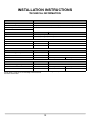
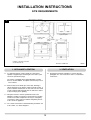
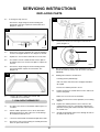
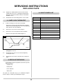
1
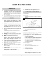
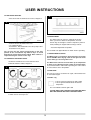
Electric Cooker
Two-Oven
Instructions for Use,
Installation and Servicing
For use in GB, IE (Great Britain and Eire)
IMPORTANT
The front and top of this appliance will become hot during operation ; it is therefore recommended that a suitable guard should be
used for protection of young children, the elderly or infirm.
This appliance is guaranteed for 3 years Parts & 1 year Labour (subject to the conditions on page 3 of this Instruction manual).
These Instructions must be left with the appliance for future reference and for consultation when servicing the appliance. Please
make the customer aware of the correct operation of the appliance before leaving these instructions with them.
The commissioning sheet found on Page 3 of this Instruction manual must be completed by the Installer prior to leaving the
premises.
CONTENTS
Appliance Commissioning Checklist
Dealer and Installer Information
3
3
USER INSTRUCTIONS
4
Description
General
Ovens and Warm Front
Using the Radiant Hob
Introduction to Induction
Using the Induction Hob
Care of Cooker
Vitreous Enamel Finish
Cleaning Lids
Cleaning the Ovens
Running In
Ventilation
After Sales Information
Fault Finding
4
4
4
6
7
8
10
10
10
10
10
10
10
11
INSTALLATION INSTRUCTIONS
TECHNICAL INFORMATION
12
SITE REQUIREMENTS
13
Appliance Location
Ventilation
13
13
INSTALLATION
14
Standards
Health and Safety
Electrical Tests
Location
Electrical Connection
Final Assembly
14
14
14
15
15
16
COMMISSIONING
17
WIRING DIAGRAM
18
2
SERVICING INSTRUCTIONS
19
REPLACING PARTS
General
Fan Motor
Overheat Switches
Fan Oven Element
Grill Element
Lower Oven Element
Fan Oven Thermostat
Lower Oven Thermostat
Specialist Servicing
Short Spares List
19
19
19
20
20
20
20
21
22
22
22
APPLIANCE COMMISSIONING CHECKLIST
IMPORTANT NOTICE
Explain the operation of the appliance to the end user, hand the completed instructions to them for safe keeping,
as the information will be required when making any guaranteed claims.
ELECTRICAL CHECK
PASS
1.
Polarity Checks
2.
Earth bond continuity
3.
Insulation resistance checks
FAIL
LOCATION CHECK
1.
All clearances as stated in this instruction manual
5.
Adequate clearance in front of the appliance to allow it to be completely withdrawn
from location if required by a Service Engineer
DEALER AND INSTALLER INFORMATION
Dealer . . . . . . . . . . . . . . . . . . . . . . . . . . . . . . . . . . . . . . . . . . . . . . . .
Installation Company. . . . . . . . . . . . . . . . . . . . . . . . . . . . . . . . .
.......................................................
........................................................
.......................................................
........................................................
Contact No.. . . . . . . . . . . . . . . . . . . . . . . . . . . . . . . . . . . . . . . . . . .
Engineer . . . . . . . . . . . . . . . . . . . . . . . . . . . . . . . . . . . . . . . . . . . . . .
Date of Purchase . . . . . . . . . . . . . . . . . . . . . . . . . . . . . . . . . . . . .
Contact No. . . . . . . . . . . . . . . . . . . . . . . . . . . . . . . . . . . . . . . . . . . .
Model No. . . . . . . . . . . . . . . . . . . . . . . . . . . . . . . . . . . . . . . . . . . . .
Reg No. . . . . . . . . . . . . . . . . . . . . . . . . . . . . . . . . . . . . . . . . . . . . . . .
Serial No. . . . . . . . . . . . . . . . . . . . . . . . . . . . . . . . . . . . . . . . . . . . . .
Date of Installation . . . . . . . . . . . . . . . . . . . . . . . . . . . . . . . . . . .
This product is guaranteed for 3 years Parts & 1 year Labour from the date of installation, as set out in the terms and conditions of
sale between AGA and your local Rayburn dealer. This guarantee will be invalid, to the extent permitted by law, if the above
Appliance Commissioning Checklist is not fully completed by the installer and available for inspection by a Rayburn
engineer.
3
USER INSTRUCTIONS
INDUCTION HOB
1. DESCRIPTION
2.12
1.1
1.2
The Rayburn Electric Traditional Cooker has enamel lined
multifunctional fan oven, grill and multifunctional
conventional oven combining the classic look of the
Traditional Rayburn with a super efficient Induction or
standard Radiant hob and the newly patented Warmfront
(APP. GB 2434860).
3. THE OVENS & WARM FRONT
3.1 OVEN DOORS
To open the doors:
For a more detailed description of the Induction or Radiant
hob and their functions, turn to the User Section 4 and 5.
•
2. GENERAL
2.1
As manufactures and suppliers of cookers and heating
products we ensure these products meet all safety
requirements when properly used and installed. To this
end, our products are thoroughly examined and tested
before delivery.
2.2
WARNING: We consider the full outer casing of this
cooker to be a working surface which becomes hot whilst
in operation. Keep young children away from the cooker
whilst it is hot and ensure they cannot reach pans and
utensils on the hob.
2.3
2.4
Do not place knives, forks, spoons and lids on the
hob surface since these can get hot.
Lift upwards and out from the left end of the handle as
illustrated
1
AR2021
Parts of the cooker become very hot when in use and
remain hot for a long period after use (e.g. Radiant hob
and ovens):
To close:
• Avoid touching the heating elements inside the oven
3.2 INTERIORS
• Use oven gloves whenever appropriate.
The ovens on the right of the cooker are lined with vitreous
enamel to provide a superb finish and easy cleaning.
• Use a 'gentle' slamming movement
WARNING: If the ceramic glass surface is cracked, switch
off the appliance to avoid the possibility of electric shock.
2.5
DO NOT use steam cleaners to clean the oven.
2.6
No alterations to the cooker should be carried out
whatsoever. Do not adjust any sealed components
because this may effect both the performance of the
appliance and your own safety.
2.7
A cooker that is incorrectly installed, altered in any way or
not serviced can invalidate approval of the appliance, its
warranty and may affect your statutory rights.
2.8
DO NOT place combustible materials onto the hotplate
surfaces even when the cooker is off.
2.9
DO NOT spray aerosols in the vicinity of this appliance
while it is operating.
The smooth stainless steel runners support shelving with
integrated safety features:
a) They are extremely strong
b) When extended a shelf 'stop' prevents the shelf being
pulled so far out it becomes unstable
c) The shelf includes an raised back edge to prevent
dishes sliding backwards as the shelf is pulled out
d) The shelves are reversible, the underside performing
as a traditional sliding shelf
Accessories Supplied
2.10 Dragging pans or utensils across the glass surface
scratches the glass.
2.11 Do not use unstable saucepans and always position
handles away from the edge of the hotplate.
4
1)
Two wire oven shelves **
2)
Large (oven-size) roasting pan with wire trivet*
3)
Grill pan with wire trivet
4)
Removable grill pan handle
**
All shelves and trays are interchangeable across both
ovens
*
Half size roasting tins are available (2 of these exactly
fit the oven depth)
USER INSTRUCTIONS
3.4 REPLACING SHELVES
4
• Place shelf onto the stainless steel runner, Diagram 2
2
AR2024
3.6 WARM FRONT
The Warm Front can either be switched ON or OFF.
When you turn the dial to the ON position, the front
and its edge are brought to a warm temperature (warm to
touch) imitating the original solid fuel range cookers.
AR2022
• Push the shelf to the back of the oven
• Let it drop into place
• Pull forward - this demonstrates the safety stop feature
described in 3.2 b) above
• You cannot adjust this temperature
The left-hand neon light indicates the Warm Front is operating.
You can also turn the shelves upside down so that they
perform in the conventional way without stops or raised
back edge to prevent heavy dishes sliding. Extra cautions is
required if using the shelves in this way.
3.7 WARM FRONT & OVENS
The Warm Front is excellent for drying tea towels and cloths
but we DO NOT advise drying cloths on the right side of the
cooker when you are using either oven.
3.5 CONTROLS AND NEON LIGHTS
You find the controls for the ovens and warm front
behind the bottom left door, Diagram 3
The Warm Front switches itself off when up to temperature
or when ovens naturally bring the cooker up to temperature.
As a reminder that the warm front is operating, the neon remains
on if the switch is in the ON position.
3
3.8 FAN OVEN
The Fan Oven can be used either as a grill, a fan-assisted oven
or a fan-assisted grill.
3.9 GRILL only
• Turn the selector to point to the grill symbol
• Turn the grill thermostat dial to the desired
temperature.
The neon indicates that the grill is ON
AR2022
PLEASE NOTE THAT THE GRILLING FUNCTION MUST
ONLY BE CARRIED OUT WITH THE DOOR OPEN
Neon indicators above the top right-hand oven alert you
to which oven is currently in use.
5
USER INSTRUCTIONS
3.10 FAN-ASSISTED OVEN
3.12 LOWER OVEN
This oven option has greater speed than the
traditional oven but can be used in the
same way, offering every baking or cooking
mode.
The Lower Oven can be run as a conventional oven with optional
features:
Top element only - for browning
• Turn the selector to Fan Assisted Oven
• Turn the fan oven thermostat dial to the desired
temperature
Bottom element - for cooking bases, i,e flans
The neon indicates that the oven is ON
Both elements - for traditional roasting and baking
To defrost:
• Turn the Lower Oven thermostat to the desired
temperature
• Turn the Fan-Oven thermostat to De-frost
• Keep the door ajar to help the air circulate during
defrost
The neon indicates when the oven is heating up and goes out
when the desired temperature is reached.
To bake or roast:
3.13 BOTH FAN OVEN AND LOWER OVEN
• Turn the Fan-Oven thermostat to your desired
temperature
• Remember to turn the right dial to the OFF
position and the left to OFF when you have
finished cooking
3.11 GRILL + FAN
The grill and fan option is a function used to
help prevent singeing or burning of grilled
foods
Venting
Both ovens are fitted with vents which remove
excess steam from the oven. This steam leaves
through specially designed ducts in the flue shroud
at the rear of the cooker. Plumes of steam from
here are quite normal and prevent excessive
condensation inside the ovens.
5
4. USING THE RADIANT HOB
AR1982
• Turn the selector to Grill + Fan
• Turn the Grill thermostat to the required
temperature but no higher than shown on the dial
as Maximum for Fan Grill.
To use either of the hobs, the appropriate hob lid must be
in the raised position. If one of the lids is lowered when the
burner underneath it is activated, then the burner
automatically turns off. It comes on again if the lid is raised
again.
Never exceed this setting to prevent overheating
6
USER INSTRUCTIONS
4.2.2 Zones
4.1 TURNING THE HOB ON
When the hob is first switched on, only the inner
zone is heated. For faster heating, touch the 'zone'
key to turn on the other zones.
• Touch the On/Off key to turn the Hob on. You
hear a short beep. The display shows ‘0’.
A decimal point indicates each hob is waiting for activity. If there
is no activity within 10 seconds of switching the hob on, you hear
a further short beep as the hob returns to Off.
• Touch the 'Z' key to turn on the second ring. A
neon lights above the 'Z' key showing the second
zone is active.
4.1.1 Locking the Hob
• Touch the 'Z' key again to bring the third ring (lefthand hob only).
• Touch the Lock to stop all hob activity for safety
purposes.
• Touch the 'Z' key again to return to the inner zone
only.
When using this Child Lock feature all key activities are
disabled.
4.4 TURNING OFF A HOB
The Child Lock feature can only be activated when the hob is
switched on and in 'wait' mode. Once activated, each hob's
control remains Locked until Unlocked, even when the hob has
been switched off and switched on. A light above the Lock
symbols shows it is active.
4.4.1 To turn a right or left hob off:
• Touch the Plus and Minus keys together
to turn a hob off
• Touch the Minus key until '0" is
displayed
WARNING: The display shows ‘H’ if the hob remains hot
after use.
If there is no activity within 10 seconds of '0' displaying, the hob
automatically switches to off.
4.2 INCREASING TEMPERATURE and INSTANT BOOST
• Touch the On/Off key to turn the Hob on
4.4.2 The On/Off key also turns both cooking hobs off.
4.5 DECIMAL DISPLAY
• Touch the Plus key to activate the left or right hob.
The decimal point in the display shows when the
hob is activated or in Wait mode.
The hob you selected automatically switches to a medium
temperature of '4'.
A - automatic heat-up takes temperature to 100%
before returning to your chosen setting
H - WARNING: the hob's surface remains hot
E - WARNING - See Fault Finding
• Touch the Plus key again to move the hob
through settings 1 - 9
• Touch the Minus key to decrease the setting
4.6 BUILT-IN FAN
• Touch and hold Minus to move the hob through
settings 9 - 1
When the hob is hot an internal fan is automatically turned on to
keep the internal components cool. This turns off when the hob
has cooled.
5. INTRODUCTION TO INDUCTION
4.2.1 Instant Boost
5.1 INTRODUCTION
To move instantly to the highest setting:
Induction is relatively new and is based on magnetic field
technology introducing huge advantages in safety, speed and
control.
• Touch the On/Off key to turn the hob on.
• Touch the Minus key. This takes the temperature
to the highest setting of '9'.
The Induction hob works by using a magnetic current to
concentrate heat within the base of the pan rather than the
ceramic surface of the hob. The only part of the ceramic surface
to warm up is that part directly beneath the metal of the pan. The
7
USER INSTRUCTIONS
contents are, in fact, heated by the pan. The pan rapidly reaches
the chosen temperature and quickly stops any cooking when
lifted away from the hob surface. It is this flexibility, speed and
control that many cooks find attractive.
6. USING THE INDUCTION HOB
Note:
You can only use pans that have a magnetic core. The
following are suitable for use with induction :
• Stainless steel
• Cast Iron
• Enamel on steel pans with non-stick interior
NOT Aluminium
To test whether your pan is suited to Induction, hold a fridge
magnet to the base of the pan; if the magnet sticks, it is
suitable for use on the Induction hob. Most modern pans are
marked to indicate whether they are suitable for induction
before purchasing.
6
5.2 ADVANTAGES
The speed of Induction compared to Gas or Radiant is
impressive. The example below shows on a 10 minute timescale
just how far ahead Induction really is:
2 LITRES OF WATER (FROM 20oC TO 90oC)
Induction
4.6 minutes
Gas
8.46 minutes
Radiant
9.00 minutes
Cast Iron
9.50 minutes
6.1 TURNING ON THE HOB
Touch the On/Off Key.
The clock timer will show CL (Clock) and the display
for the two cooking zones will illuminate with a
dot flashing beside each of them to show that they are awaiting
a selection.
Data compiled by E.G.O.
1. Energy Consumption is minimised. Only contact with a
suitable pan activates the magnetic current; a hugely efficient
way to use electric resources. The hob stops producing any
current when the pan is lifted and until it is returned.
Each time a touch control has been activated the hob will give a
beep to confirm.
2. Cool down of contents of a pan takes a fraction of the time f
or Radiant, Gas and other fuels.
If a selection is not made within 20 seconds the hob will
automatically power off. The unit will beep when powering
down. See Fig. 6
3. The response to temperature control is swift and precise.
6.2 CONTROLLING A COOKING ZONE
4. Only the area beneath the saucepan is heated - the rest of
the hob surface stays cool.
Turn on the hob by touching
Touch the display of the cooking zone.
5. The Induction Burner automatically adjusts its power
depending on the size of the pan. The smaller the pan the
less energy used.
Then touch the slider, for a high setting touch the right hand end
of the slider for a low setting touch the left hand end. With your
finger remaining in contract with he slider the set pint can be
increased /decreased by sliding your finger in the appropriate
direction.
6. Soap and water are all it takes to clean.
8
USER INSTRUCTIONS
6.3 WARNING
between “A” and the power level selected. After the pre-heat
time has elapsed the power level will reduce to the level selected
and the display will no longer flash “A” and will display the power
level.
The display shows ‘H’ if the hob remains hot after use. The heat
is producted by pans resting on the hob and is not induced heat.
6.4 LOCKING THE HOB
Note the preheat time is dependent on the power level. The
higher the power level selected the longer the preheat time will
be.
When using this child lock feature all key activities are disabled.
The child lock feature can only be activated when the hob is
switched on and the dots beside both cooking zone displays are
flashing.
6.8 SETTING THE TIMER
Touch the display for the required cooking zone. Touch the
slider and select power level.
Touch the clock display, and adjust the digits on the clock
display using the slider. The timer can be setup to a max of 99
minutes.
To lock the display touch the “boost” and “Right hand cooking
zone” keys simultaneously, then release and touch the “right
hand cooking zone key”. The two cooking zone displays should
now show “L” for locked.
The hob will remain locked even if it is powered down and
powered back up again.
See example of display when right hand cooking zone is set to
power level 2 for a duration of 08 minutes. The clock will count
down until it reaches 0, it will then beep and the cooking zone
will switch off. See Fig 7.
To unlock the display, power off the hob and power it on again.
Touch the “boost” and “right hand cooking zone” keys
simultaneously then release and press the boost key. The hob
should power off automatically to confirm that the unlock has
been successful.
7
6.5 BOOST
The boost function can be selected to reduce heat up times,
boost will heat the pot over a cooking zone significantly faster
than setting 9. Boost will last for 10 minutes or until the user
intervenes.
To boost a cooking zone, select the cooking zone and touch the
boost key. When boost is selected “P” will be displayed in the
cooking zone display.
6.6 PAN SENSOR
6.9 LOW TEMPERATURE CONTROL
WARNING: This symbol is displayed when the
hob cannot sense a pan on its surface. If a pan
is not in contact with the surface after switching
on a hob, both hobs automatically switch off.
The low temperature control allows three different temperatures
to be selected. Denoted by
(one bar),
(two bars),
(three bars). One bar is the lowest set temperature and three
bars is the highest.
This symbol also indicates when the wrong type of pan is placed
on the surface. Induction does not recognise aluminium and
other non magnetic metals.
To use this function select a cooking zone and then repeatedly
touch the low temperature button until the desired level is
achieved. i.e
,
or
in the cooking zone display.
6.7 PRE-HEAT FUNCTION
6.10 PAUSE
This function allows for rapid heat up to bring the selected zone
up to temperature, followed by an automatic switch over to a
preset power level.
When a cooking zone is in operation the hob can be paused.
when the hob is paused the symbol “II” will be displayed in both
cooking zone displays.
To Activate The Pre-Heat Function
To pause the hob press both cooking zone displays
simultaneously. To restart a paused hob press both cooking
zone displays simultaneously then release “II” symbols will flash,
press anywhere on the slider.
Select the cooking zone, then press the right hand end of the
slider, the display will show “9” then press the right hand end
again and the display will show “A”. Select the power level
required following the heat up time. The display will now flash
9
USER INSTRUCTIONS
7. CARE OF THE COOKER
9. CLEANING THE LIDS
7.1 COOKER MAINTENANCE
9.1 The inside of each lid can be cleaned using wire wool and
soapy water while following the grain of the stainless steel
to keep it looking new.
7.1.1. Care of the Induction and Radiant Hob
The smooth surface of the ‘zones’ for each hob type are easy to
keep clean. Ensure the ceramic surface is cool or cold
before cleaning:
•
Clean the ceramic glass after each use to prevent any light
spillage becoming embedded.
•
Light cooking spatters can be removed with a damp cloth and
washing-up liquid. Rub dry with a clean cloth.
•
10. CLEANING THE OVENS
10.1 The two ovens are coated in a vitreous enamel finish for
easy cleaning. Again, do not use wire wool as this can
damage the enamel finish. Normal oven cleaning products
can be used.
10.2 Doors can be lifted off their hinges to clean. DO NOT
immerse the whole door in water because this will effect the
insulation in the door.
Heavy spatters on the Radiant hob, including scale and
water marks, fat spots and discolouration can be removed
using a ceramic glass product generally sold for cleaning
ceramic hobs. Use clean water to rinse off the cleaner and
rub to finish with a dry cloth.
•
Remove stubborn splashes with a glass scraper:
•
Slide the blade of the glass scraper at an angle to
loosen the stubborn deposits
11. RUNNING IN
11.1 The new surface coating on your Rayburn cooker will “burn
off” to create a harmless odour during its first hours of use.
The smell will disappear after a short period but if it persists
ask your installer for advice.
12. VENTILATION
Do not use an abrasive oven spray, scourer or pan cleaner
on the Radiant hob surface.
12.1 You may need to open a window or increase mechanical
ventilation during prolonged use of the cooker.
Because the cooking heat of the Induction Hob is produced
within the pan, rather than the hob surface, spatters onto the
Induction ceramic are unlikely to be heavy and will not continue
cooking to a burnt-on condition.
13. AFTER SALES INFORMATION
7.1.2. Cleaning the Radiant Hob while it is Hot
On occasion, when tough substances like sugar or plastic have
melted onto the hob surface, clean as soon as possible with the
glass scraper while the hob is still hot, TAKING CARE NOT TO
BURN YOURSELF.
13.1 The Commissioning sheet at the front of this book must be
completed by your installer. This records the essential
installation details. In all correspondence, you must quote
the Model and Serial Number which can be found on the
Data badge behind the control door.
IMPORTANT: Ensure you use clean water to remove ALL
cleaning agents from the ceramic glass before re-heating.
The caustic nature of cleaning products may damage the
glass surface.
13.2 We provide a 3 year Parts & 1 year Labour warranty and a
nationwide network of qualified Field Service Engineers
who are available to attend a breakdown or manufacturing
fault while the cooker is under guarantee.
8. VITREOUS ENAMEL FINISH
13.3 Below is a step by step guide to reporting a fault with your
appliance.
8.1 A vitreous enamel surrounds the hob and coats the front,
doors and top plate. Burnt-on food should be removed
carefully using a plastic kitchen scrubber. DO NOT USE wire
wool as this can damage the enamel finish.
In the event of a cooker fault or breakdown:
Step 1:
Always contact your installer or commissioning engineer in
the first instance. He must thoroughly check all his work
PRIOR to requesting a service visit from Rayburn Engineer.
8.2 The side panels of Rayburn cookers are powder coated
finish. Clean with a damp cloth only.
10
USER INSTRUCTIONS
Step 2:
14.2 HOBS
H - WARNING - the hob's surface remains hot
If your cooker has developed a fault during the guarantee
period, your installer should contact the AGA
Rangemaster Service Centre for assistance.
• Correct zone has been switched ON and temperature
setting has been selected.
What happens if my installer/engineer is unavailable?
ERROR CODES
Step 3:
If an error code is displayed (eg. E5, E64), remove any pots and
allow the glass to cool, thoroughly clean the glass, if the problem
persists contact your Aga Rangemaster Dealer.
Contact AGA Rangemaster direct. We provide the name
and telephone number of our Service Agent. However, a
charge may apply if the fault is not covered by the cooker
guarantee; (payment is requested on site by our
independent Service Agent).
13.4 A charge is made where:
• Our Field Service Engineer finds no fault with the
cooker.
• Where the appliance falls outside the 3 year parts & 1
year Labour warranty period (See terms and conditions
enclosed).
• The appliance has not been correctly installed,
commissioned, serviced or used as recommended.
(See Commissioning, Installation and Servicing
instructions).
13.5 PLEASE NOTE:
Unauthorised invoices for attendance and repair work
carried out on this cooker by any third party are not
accepted by AGA Rangemaster.
Every enamelled part on your cooker is unique and has
its own individual characteristics. Coloured parts may
differ slightly in shading. This does not impair
performance in any way and is quite normal.
13.6 IMPORTANT CUSTOMER NOTICE
Cosmetic damage, stains and scratches produced by
cooking and cleaning are NOT covered by the statutory
guarantee.
14. FAULT FINDING
Do not attempt to repair any part of the cooker yourself.
Always contact a qualified electrical engineer or your
AGA Rangemaster Dealer.
The following guide covers minor faults relating to the hob:
14.1 GENERAL
Check whether the:
• Fuses in the fuse box are unbroken. If fuses repeatedly
switch off or blow, call a qualified electrician.
11
INSTALLATION INSTRUCTIONS
TECHNICAL INFORMATION
GENERAL
Connection Voltage
230V 50HZ
Maximum Power Rating
52 amp (Induction Hob Model)
Cooker Weight
214 Kilos
INDUCTION HOB
40 amp (Radiant Hob Model)
POWER
Right Hand Hob
Variable, depending on pan size up to 3.7kW
Left Hand Hob
Variable, depending on pan size up to 3.7kW
RADIANT HOB
Right Hand Hob
Dual Circuit
1.5kW - 2.4kW
Left Hand Hob
Triple Circuit
1.05kW - 1.95kW - 2.7kW
FAN OVEN
POWER
Fan Oven - Energy Rating = ‘B’**
2.5kW
Grill
2.55kW
Usable volume - Litres = 37
Oven Width = 355mm
Oven Depth = 460mm
LOWER OVEN
POWER
Lower Oven - Energy Rating = ‘C’**
Up to 2kW
Usable volume - Litres = 37
Oven Width = 355mm
Warmfront
Oven Depth = 460mm
Oven Height = 240mm
Oven Height = 240mm
160 Watts
** Energy consumption tested to BS EN 50304:2001
Rated voltage, Serial No etc on Data badge which is located
behind the control door.
12
INSTALLATION INSTRUCTIONS
SITE REQUIREMENTS
1
10mm clearance to Work top
457
Square lid option
694
10mm clearance
to Wall
Services duct
988
Position of door
when open
908
986
1393 Approximately
Position of
lid when
raised
500mm minimum
clearance
Work top
643
668
976
Important - Electrical connections
are left hand side only
Dimensions in Millimetres
AR2008
2. VENTILATION
1. APPLIANCE LOCATION
1.1 It is important that the cooker stands on a flat surface
capable of supporting the total weight of the cooker, (See
Technical Specification page).
2.1 No purpose provided ventilation is required, but note
paragraph 12.1 User Instructions and 1.1 of Installation
Instructions.
The cooker is supplied with a plinth adjustable in height
between 80 and 100mm. This plinth can also help to level
uneven floors.
1.2 Kitchen units can be fitted up to either side, allowing a
10mm gap between the kitchen surfaces and the cooker. If
a pine or similar wood surface is used, take care the wood
is well seasoned and protected from the side of the cooker
to prevent drying out or splitting.
1.3 Adequate clearance must be provided in front of the
appliance to allow it's complete removal from the location.
Certain serviceable components can only be changed by
removing the cooker from it's location and gaining access
to the rear of the appliance.
1.4 The electric connection is channelled along the bottom left
of the cooker, see above Diagram 1.
13
INSTALLATION INSTRUCTIONS
INSTALLATION
IMPORTANT
1. STANDARDS
1.1
The wires in the mains lead are coloured in accordance
with the following code:
This appliance should be installed according to
regulations in force and only used in a well-ventilated
space. Read these instructions before installing or
operating.
- green/yellow Earth
- blue Neutral
1.2
1.3
The Electric Traditional Cooker must be installed by a
competent person in accordance with the Requirements
of Electrical Installations, IEE Wiring Regulations, 17th
Edition.
- brown Live
4.4
The person(s) who installs this appliance, commissions,
services and carries out remedial work (e.g. electrical fault
finding), must have proven electrical competency.
2. HEALTH & SAFETY
2.1
Every reasonable care is taken to ensure products
are designed and constructed to meet all general safety
and performance requirements when properly used and
installed (BS EN 60335 - 1:2002, BS EN 60335 - 6 :2003).
We manufacture under our quality system accredited to
ISO 9000. This standard means products are
comprehensively tested and examined before despatch.
2.2
This appliance is heavy and care must be taken when
installing. Use suitable equipment to prevent injury.
3. ELECTRICAL TESTS
ELECTRICAL WARNING
INSTALLATION OF THIS COOKER IS TO BE CARRIED
OUT BY A QUALIFIED ELECTRICIAN TRAINED IN THE
USE OF SPECIALIST EQUIPMENT.
WIRING EXTERNAL TO THE APPLIANCE MUST BE IN
ACCORDANCE WITH THE CURRENT IEE WIRING
REGULATIONS, 17th Edition.
3.1
The voltage and the electrical load information are printed
on the product serial number label.
3.2
The appliance must be connected to the correct electrical
supply with a minimum 10mm2 cable and a suitable
cooker control unit incorporating a double pole switch
having a contact separation distance of at least 3mm.
WARNING: THIS APPLIANCE MUST BE EARTHED
14
Should the mains lead of the appliance ever require
replacing, we recommend that the operation is carried out
by a qualified electrician.
INSTALLATION INSTRUCTIONS
INSTALLATION
3
4. LOCATION
• Decide on where the cooker is to be located, see Site
Requirements
• Install the electrical supply up to the cooker switch, see
3.2
YOUR COOKER SHOULD REMAIN ON THE PALLET.
1
AR2030
• Slide off the pallet onto the plinth
• Check the cooker surface is level with the kitchen
surfaces (if any)
• Check the cooker itself is level using a spirit level
AR2025
5. ELECTRICAL CONNECTION
• Place the plinth in the intended location
LEVELLING THE COOKER
• Remove the magnetic side panel of the cooker
To access the plinth's four levelling feet, Diagram 2
4
2
AR2026
AR2027
• Adjust the level and height of the cooker by adjusting
each of the four legs of the plinth in turn:
• Remove the control panel cover behind the bottom lefthand door by removing the four screws shown
• Use a 19mm open-ended spanner
5
The height of the plinth PLUS the height of the cooker
EQUALS the same height as kitchen surfaces (if any)
MAKE SURE YOU HAVE ASSISTANCE AS THE
COOKER IS HEAVY
• Manoeuvre the cooker on its pallet in front of the plinth
IF THE KITCHEN UNITS ARE CLOSE TO THE LEFTSIDE OF THE COOKER, YOU MAY NEED TO MAKE
THE ELECTRICAL CONNECTION TO THE COOKER
BEFORE IT SLIDES BACK INTO POSITION.
AR2028
15
INSTALLATION INSTRUCTIONS
INSTALLATION
• Fit the two towel rail cast iron ends to the rail
6
• Lock with the hex grub screw, Diagram 9
9
Mains cable
clamp
AR2035
• Feed the 10mm mains cooker cable through the channel
and into the cooker, Diagram 6
AR2031
7
• Fit the towel rail assembly onto the threaded bar
ensuring the gasket is fitted as in the following Diagram
10
10
AR2029
• Connect the mains cable to the connector block
following the label identification, Diagram 7
• Replace the control cover and magnetic side cover
AR2033
6. FINAL ASSEMBLY
6.1.
• Lock the towel rail assembly by fitting a washer and nut,
Diagram 11
Towel Rail
11
• Screw the threaded bar into the cooker top (both sides)
• Fit a washer and nut
• Screw the threaded bar in until it touches the cooker
front and lock the nut in position, Diagram 8
8
Underside of rail
nt
Fro
l
ne
Pa
Underside of front rail
AR2031
16
AR2034
INSTALLATION INSTRUCTIONS
COMMISSIONING
7. COMMISSIONING
ON COMPLETION, THE INSTALLATION MUST BE
CHECKED FOR SAFETY. THE TESTS MUST INCLUDE:
• POLARITY CHECK
• EARTH BOND CONTINUITY
• INSULATION RESISTANCE CHECK
IMPORTANT
IF THERE IS NO MAINS SUPPLY OR THE ABOVE
TESTS CANNOT BE CARRIED OUT, ENSURE THAT A
WARNING LABEL IS ATTACHED TO THE APPLIANCE
STATING THAT IT SHOULD NOT BE USED UNTIL
ELECTRICALLY TESTED BY A SUITABLY QUALIFIED
ELECTRICIAN AND INFORM THE CUSTOMER.
Finally:
• Complete the Appliance Commissioning Checklist on
page 3 of this User and Installation guide.
17
SERVICING INSTRUCTIONS
WIRING DIAGRAM
18
SERVICING INSTRUCTIONS
REPLACING PARTS
IMPORTANT
The work must be carried out by trained service engineers.
1. GENERAL
2
IMPORTANT – The glass panel on this appliance should be
checked for any signs of damage on the front face of
the glass panel (scratches, scores, cracks or other
surface defects). If damage is observed, the glass
panel must be replaced and the appliance must not be
used until a replacement is installed. Under no
circumstances should the appliance be used if any
damage is observed. Please isolate the appliance
until a replacement glass panel has been obtained
and installed. Replacement glass panels can be
purchased from AGA Rangemaster via the dealer from
which the appliance was purchased or any other
AGA Rangemaster distributor.
1.1
AR1557
All major components can be replaced from the front of
the cooker.
1.2
2.3
• Remove the top two screws 'A', retaining the fan
assembly panel and loosen the bottom two screws 'B'
2.4
• Lift the fan assembly panel up and off
Make sure the mains electrical supply is isolated before
carrying out any servicing work.
• Lower onto the floor of the oven
• Remove all wires, but keep the Yellow Link wire, see
Diagram 3
BEFORE PROCEEDING TO CHANGE OR SERVICE
ANY ELECTRICAL ITEMS ISOLATE THE MAINS
ELECTRIC.
3
2. FAN MOTOR
2.1
• Open the Fan Oven door and loosen the four screws
holding the fan cover. Lift the fan cover off the screws.
See Diagram 1.
1
AR1592
2.5
• Remove the central nut (left-hand thread) and separate
the impeller from the fan motor, See Diagram 4 Arrow A
AR1587
4
AR1587
B
2.2
B
• Remove the thermostat phial, lifting it vertically from its
brackets. Take care not to damage the fine capillary
tube. See diagram 2, C
AR1594
19
SERVICING INSTRUCTIONS
REPLACING PARTS
2.6
• Remove the three screws (Arrow B) and the fan motor
from the panel, Diagram 4.
2.7
• Replace the fan motor and reassemble in reverse order
4.2
Remove the three screws retaining the oven element and
carefully pull forward the element to expose the
connections. See diagram 7, Arrow C.
7
3. OVERHEAT SWITCHES
C
3.1
There are two overheat switches located on the rear of
the fan oven assembly panel.
C
C
To replace either of these switches, follow steps 2.1 to 2.4
above:
• Remove the two fixing screws from the defective switch
identified, Diagram 5
AR1557
5
4.3
4.4
• Disconnect the wires making sure they do not fall
behind the oven.
• Replace the element and reassemble in reverse order.
5. GRILL ELEMENT
5.1
Remove the single screw from the rear of the element
and the two screws retaining the support bracket.
See diagram 8.
AR1592
3.2
• Replace the overheat switch and reassemble in reverse
order ensuring no wires are trapped when replacing the
fan
3.3
There is also an overheat switch on the Lower Oven
element. To access this follow Section 6
8
4. FAN OVEN ELEMENT
4.1
AR1587
• Open the Fan Oven door and loosen the four screws
holding the fan cover
5.2
Carefully pull the element forward to expose the
connections and disconnect the wires making sure they
do not fall behind the oven.
5.3
Replace the element and reassemble in reverse order.6.
• Lift the fan cover of the screws, Diagram 6
6
6. LOWER OVEN ELEMENT
6.1
There are two elements in the Lower Oven:
• One in the top of the oven
• One under the loose plate of the bottom
AR1587
20
SERVICING INSTRUCTIONS
REPLACING PARTS
6.2
11
To change the top element:
• Remove the single fixing screw and carefully pull
forward the element to expose the connections. See
diagram 9, Arrow A.
9
AR2028
7.5
B
B
A
12
AR1559
6.3
• Remove the two wires and draw the element forward to
clear the two support brackets. See diagram 9, Arrow B.
6.4
• Replace the element and reassemble in reverse order.
6.5
• The bottom element is situated under a loose plate in
the bottom of the oven. Remove the plate to expose the
element.
6.6
• Remove the single fixing screw and carefully pull the
element forward to expose the connections. See
diagram 10.
• Remove the two screws securing the control to the
panel, Diagram 12
AR1591
10
7.6
Note the positions of all the wires and disconnect the
control. Alternatively, transfer each wire to the new control
individually.
7.7
Working from inside the controls area:
• Carefully pull the phial through.
• Take care that it has not become wrapped around the
other phial
• Remove the vidaflex protective sleeve
7.8
AR1558
6.7
• Make sure it is in the correct orientation
• Remove the wires, replace the element and
reassemble in reverse order.
7.9
7. FAN OVEN THERMOSTAT
7.1
• To replace the Fan Oven Thermostat, follow steps 2.1 to
2.4 above:
7.2
• Pull the vidaflex protective sleeve off the thermostat
phial and keep for use later. Take care not to damage
the insulation behind the oven.
7.3
• Locate the fault control thermostat and pull off the knob
7.4
• Remove the four screws securing the control panel and
lower the panel onto its front
• Replace the defective control with a new one and secure
it to the front panel
• Replace the wires in the correct positions, refer to wiring
diagram
7.10 • Replace the vidaflex protective sleeve from the old
control onto the new one, ensuring that it protects the
phial from coming into contact with other connections in
the control area
7.11 • Thread the phial back and feel for it through the hole in
the back of the Fan Oven
21
SERVICING INSTRUCTIONS
REPLACING PARTS
7.12 • Replace the vidaflex protective sleeve from the old
control onto the new one, ensuring that it protects the
phial from coming into contact with other connections
behind the oven
10. SHORT SPARES LIST
7.13 • Reassemble the fan assembly panel in reverse order
8. LOWER OVEN THERMOSTAT
8.1
In order to change the Lower Oven thermostat:
• Remove the Fan Oven Fan Assembly plate to provide
sufficient access following steps 2.1 to 2.4 of Replacing
Parts, but leave the wires attached
8.2
• Remove the Lower Oven element, Step 6.2
8.3
• Remove the Lower Oven phial 'A' from its location
• Remove access panel 'B' behind, Diagram 13
13
B
B
A
AR1559
8.4
• Replace the thermostat and phial by following
paragraphs 7.2 to 7.12
8.5
• Reassemble the Lower Oven element and phial by
reversing the order
8.6
• Reassemble the Fan Oven assembly by reversing the
order
9. SPECIALIST SERVICING
In the unlikely event that a problem occurs with any of the
following features:
- Induction Hob
- Radiant Hob
- Neon Indicators
- Warm Front
The parts are serviceable only by an authorised Rayburn
Service engineer; contact your local Rayburn agent.
22
EL0314
Oven Pre-set 220oC
EL0298
Grill Element
C610138
Grill Trivet
EL0299
Bottom Oven Element
C610077
Wire Cooking Shelf
C610335
Full Size Baking Tray Trivet
C610334
Full Size Baking Tray
EL0301
Fan Oven Element
EL0300
Fan Oven Fan
GC0113
Control Knob
EL0309
Grill Thermostat
EL0310
Oven Thermostat
EL0412
Rotary Switch
SERVICE RECORDS
1ST SERVICE
Date of Service:...........................................................................
Next Service Due:.......................................................................
Signed:........................................................................................
Dealer's Stamp Registration Number
2ND SERVICE
Date of Service:...........................................................................
Next Service Due:.......................................................................
Signed:........................................................................................
Dealer's Stamp Registration Number
3RD SERVICE
Date of Service:...........................................................................
Next Service Due:........................................................................
Signed:........................................................................................
Dealer's Stamp Registration Number
4TH SERVICE
Date of Service:...........................................................................
Next Service Due:.......................................................................
Signed:........................................................................................
Dealer's Stamp Registration Number
5TH SERVICE
Date of Service:...........................................................................
Next Service Due:.......................................................................
Signed:........................................................................................
Dealer's Stamp Registration Number
6TH SERVICE
Date of Service:...........................................................................
Next Service Due:.......................................................................
Signed:........................................................................................
Dealer's Stamp Registration Number
7TH SERVICE
Date of Service:...........................................................................
Next Service Due:.......................................................................
Signed:........................................................................................
Dealer's Stamp Registration Number
8TH SERVICE
Date of Service:...........................................................................
Next Due:........................................................................
Signed:........................................................................................
Dealer's Stamp Registration Number
9TH SERVICE
Date of Service:...........................................................................
Next Service Due:.......................................................................
Signed:........................................................................................
Dealer's Stamp Registration Number
10TH SERVICE
Date of Service:...........................................................................
Next Service Due:.......................................................................
Signed:........................................................................................
Dealer's Stamp Registration Number
23
Manufactured by AGA Rangemaster
Station Road, Ketley, Telford, Shropshire, England TF1 5AQ
England, Scotland & Wales Tel: 0845 6010398
www.agaliving.com
Northern Ireland Tel: 02891 270233
www.agacookshop.co.uk
www.rayburn-web.co.uk
N00532AXX
24