1
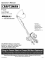
Operator's
Manual
M
4-Cycle
Lawn Edger
Model No. 316,772380
INCREDI.PULL
TM
UNBELIEVABLE
with
MA×
STARTING
EA SE
FIREx4clI3NITION
M
,, SAFETY
* ASSEMBLY
* OPERATION
* MAINTENANCE
* PARTS LIST
* ESPANOL, R 13
CAUTION:
Before using this
product, read this manual and
follow
all safety rules and
operating
instructions.
Sears Brands
Management
Corporation,
Visit our website:
P/N 769=05248 P00
Hoffman
Estates,
IL 60179 U.S.A.
www.craftsman.com
11/09
CALiFORNiA
PROPOSiTiON
65 WARNING
The purpose of safety symbols is to attract your attention to possible dangers.
The safety symbols, and their explanations, deserve your careful attention and
understanding. The safety warnings do not by themselves eliminate any danger.
The instructions or warnings they give are not substitutes for proper accident
prevention measures.
THE ENGINE EXHAUST FROM THiS PRODUCT CONTAINS CHEMICALS
KNOWN TO THE STATE OF CALiFORNiA TO CAUSE CANCER, BIRTH
DEFECTS OR OTHER REPRODUCTIVE HARM.
SYMBOL
TABLE OF CONTENTS
Safety Rules .................................................
Warranty ....................................................
Know Your Unit ...............................................
2
4
4
Assembly Instructions ..........................................
Oil and Fuel Information ........................................
4
5
Starting/Stopping
6
Instructions
...................................
Operating Instructions
.........................................
Maintenance and Repair Instructions ..............................
6
7
Cleaning and Storage
..........................................
9
Optional Equipment
...........................................
Troubleshooting Chart ........................................
9
10
Specifications
...............................................
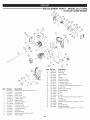
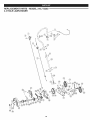
Parts List ...................................................
11
30
Service Numbers
SPARK ARRESTOR
.....................................
MEANING
Attention is ALERT:
required inIndicates
order to avoid
personal
injury.
SAFETY
danger,serious
warning
or caution.
May be used in conjunction with other symbols or pictographs.
injury
to yourself
or to to
others.
thewill
safety
precautions
DANGER:
Failure
obey Always
a safety follow
warning
result
in serious
to reduce the risk of fire, electric shock and personal injury.
injury to yourself Failure
and others.
Always
follow
the safety
precautions
WARNING:
to obey
a safety
warning
can result
in
to reduce the risk of fire, electric shock and personal injury.
_IL
NOTE:
property
damage
or personal
to warning
yourself or
others.in
CAUTION:
Failure
to obey injury
a safety
mayto result
Always follow the safety precautions to reduce the risk of fire,
electric shock and personal injury.
Advises of information or instructions
maintenance of the equipment.
vital to the operation or
Back Cover
NOTE=
NOTE
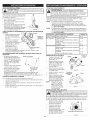
NOTE: For users on U.S. Forest Land and in the states of California, Maine,
Oregon and Washington. All U.S. Forest Land and the state of California (Public
Resources Codes 4442 and 4443), Oregon and Washington require, by law that
certain internal combustion engines operated on forest brush and/or grass-covered
areas be equipped with a spark arrestor, maintained in effective working order, or
the engine be constructed, equipped and maintained for the prevention of fire.
Check with your state or local authorities for regulations pertaining to these
requirements. Failure to follow these requirements could subject you to liability or
a fine. This unit is factory equipped with a spark arrestor. If it requires
replacement, ask your LOCAL SERVICE DEALER to install the Accessory Part
#753=05245 Muffler Assembly.
This Unit Can Use a Plug=in Power Start or Power Bit Start
Optional Accessory!
Please refer to the Plug-In Power Start or Power Bit Start operator's
manual for proper use of these features. (Items may be Sold
Separately! Please refer to page 9 of this manual for more information
about purchasing these accessories.)
Read the Operator's Manual and foflow all warnings and safety instructions.
Failure to do so can result in serious injury to the operator and/or bystanders.
FOR QUESTIONS, CALL 1=800=4=MY=HOME®.
All information, illustrations, and specifications in this manual are based on the
latest product information available at the time of printing. We reserve the right
to make changes at any time without notice.
• iMPORTANT SAFETY iNSTRUCTiONS
READ ALL iNSTRUCTiONS
BEFORE OPERATING
followed. Please read these instructions before operating the unit
in order to ensure
the using
safety the
of the
anymust
bystanders.
WARNING:
When
unit,operator
all safetyand
rules
be
Please keep these instructions for later use.
_
• Avoid creating a source of ignition for spilled fuel. Do not start the engine until
fuel vapors dissipate.
J
• Read the instructions carefully. Be familiar with the controls and proper use of
the unit.
Never start or run the unit inside a closed room or building. Breathing exhaust
fumes can kill. Operate this unit only in a well ventilated outdoor area.
Inspect the unit before use. Replace damaged parts. Check for fuel leaks.
Make sure all fasteners are in place and secure. Replace parts that are
cracked, chipped, or damaged in any way. Do not operate the unit with loose
or damaged parts.
Wear safety glasses or goggles that are marked as meeting ANSI Z87.1-1989
standards. Also wear ear/hearing protection when operating this unit. Wear a
face or dust mask if the operation is dusty. Long sleeve shirts are
recommended.
Carefully inspect the area before starting the unit. Remove all debris and hard
or sharp objects such as glass, wire, etc.
Wear heavy, long pants, boots and gloves. Do not wear loose clothing,
jewelry, short pants, sandals or go barefoot. Secure hair above shoulder level.
This unit has a clutch. The blade remains stationary when the engine is idling.
If they do not, have the unit adjusted by an authorized service technician.
Be sure the blade is not in contact with anything before starting the unit.
Be aware of the risk of injury to the head, hands and feet.
Clear the area of children, bystanders, and pets. At a minimum, keep all
children, bystanders, and pets outside a 50 feet (15 m.) radius; there still may
be a risk to bystanders from thrown objects. Bystanders should be
encouraged to wear eye protection. If approached, stop the unit immediately.
Squeeze the throttle control and check that it returns automatically to the idle
position. Make all adjustments or repairs before using unit.
SAFETY WARNINGS FOR GAS UNITS
_
explode
if ignited.
Take the
following
precautions:
WARNING:
Gasoline
is highly
flammable
and its vapors can
Store fuel only in containers specifically designed and approved for the
storage of such materials.
engine and allow it to cool before filling the fuel tank. Never
of the fuel tank, or add fuel, when the engine is hot. Never
without the fuel cap securely in place. Always loosen the fuel
to relieve any pressure in the tank.
• Add fuel in a clean, well-ventilated outdoor area where there are no sparks or
flames. Do not smoke while fueling. Wipe up any spilled fuel from the unit
immediately. Always wipe unit dry before using.
Move the unit at least 30 feet (9.1 m) from the fueling source and site before
starting the engine. Do not smoke or allow sparks and open flames near the
area while adding fuel or operating the unit.
WHILE OPERATING
Do not operate this unit when tired, ill, or under the influence of alcohol,
drugs, or medication.
Children and teens under the age of 15 must not use the unit, except for
teens guided by an adult.
All guards and safety attachments must be installed properly before operating
the unit.
--
• Always stop the
remove the cap
operate the unit
tank cap slowly
Use the unit only in daylight or good artificial light.
i
Avoid accidental starting. Be in the starting position whenever pulling the
starter rope. The operator and unit must be in a stable position while starting.
See Starting/Stopping Instructions.
Use the right tool. Only use this tool for the purpose intended.
Use extreme caution when reversing or pulling the unit backwards.
Do not overreach. Always keep proper footing and balance. Take extra care
when working with on steep slopes or inclines.
* Always hold the unit with both hands when operating. Keep a firm grip on the
handle.
* To reduce fire hazard, keep the engine and muffler free from grass, leaves,
excessive grease or carbon build up.
After use
* Keep hands, face, and feet at a distance from all moving parts. Do not touch
or try to stop the blade while it is rotating.
* Clean the unit with household cleaner to remove any gum buildup. Oi the
bade with mach ne oil to prevent rust.
OTHER SAFETY WARNINGS
* Do not touch the engine or muffler. These parts get extremely hot from
operation. They remain hot for a short time after turning off the unit.
* Do not operate the engine faster than the speed needed for the job. Do not
run the engine at high speed when the unit is not in use.
* Always stop the engine when work is delayed or when walking from one
location to another.
* Never store a fueled unit inside a building where fumes may reach an open
flame or spark.
* Allow the engine to cool before storing or transporting. Be sure to secure the
unit while transporting.
* If striking or becomes entangled with a foreign object, stop the engine
immediately and check for damage. Do not operate before repairing damage.
Do not operate the unit with loose or damaged parts.
* Store the unit in a dry area, locked up or up high to prevent unauthorized use
or damage. Keep out of the reach of children.
* Never douse or squirt the unit with water or any other liquid. Keep handles dry,
clean and free from debris. Clean after each use. See the Cleaning and
Storage instructions.
* Keep these instructions. Refer to them often and use them to instruct other
users. If loaning someone this unit, also loan them these instructions.
* Stop and switch the engine to offfor maintenance or repair.
* Use only original equipment manufacturer replacement parts and accessories
for this unit. These are available from an authorized service dealer. The use of
any unauthorized parts or accessories could lead to serious injury to the user,
or damage to the unit, and void the warranty.
SAVE THESE INSTRUCTIONS
* Keep unit clean of vegetation and other materials that may become lodged or
entangled in the unit.
,, SAFETY & iNTERNATiONAL
This operator's manual describes safety and international symbols and pictographs
complete safety, assembly, operating and maintenance and repair information.
SYMBOL
MEANING
SYMBOL
3
SYMBOLS •
that may appear on this product.
MEANING
Read the operator's
manual for
CRAFTSMAN
FULL WARRANTY
If this Craftsman product fails due to a defect in material or workmanship within two years from the date of purchase, return it to any Sears store, Parts and
Repair Service Center, or other Craftsman outlet in the United States for free repair (or replacement if repair proves impossible).
This warranty applies for only 90 days if this product is ever used for commercial or rental purposes.
This warranty
•
covers
ONLY defects
in material
and workmanship.
Sears will NOT pay for:
Expendable items that can wear out from normal use within the warranty period, such as cutting line, air cleaner or spark plug.
Repairs necessary because of accident or failure to operate or maintain the product according to all supplied instructions.
Preventive maintenance,
or repairs necesary due to improper fuel mixture, contaminated
or stale fuel.
This warranty gives you specific legal rights, and you may also have other rights which vary from state to state.
Sears, Roebuck and Co., Hoffman Estates, IL 60179
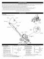
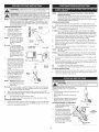
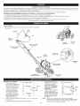
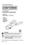
APPLICATIONS
Edging along paths, driveways,
rockeries, etc.
Handme
Bairn Lock
Throttle Contol
Oil Fill Plug
Fuel
Starter
On/Off
Control
Cap
Rope
Grip
Air Filter
Cover
Muffler
Spark
Plug
Bulb
Depth
Edger Blade
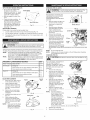
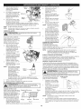
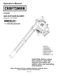
HANDLE
ASSEMBLY
1.
Remove the nuts and bolts
from the handle
components.
Be sure that
they return to the holes they
came out of.
2.
3.
4.
5.
straight middle shaft over the
lower shaft on the unit and
align the holes (Fig. 1). Make
Place the 2-holed end of the
sure the "TO START" label is
II
Middle Handle
U
_=_
Blade
Shield
6.
Bolt
4.
[_
Adjustment
Lever
Lock-Nuts
:_
Lower Handle
facing up.
Fig. 1
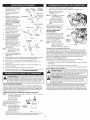
Insert the 2 flange-head bolts
(1/4" x 1-1/4") into these holes (Fig. 1).
Install the lock-nuts onto these bolts until finger tight.
Using a 3/8" wrench, hold each flange-head bolt and tighten the locknuts with a 7/16" wrench until firm. DO NOT OVERTIGHTEN.
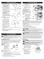
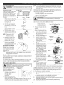
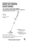
Place the upper shaft of the
control handle onto the 3-holed
end of the straight middle shaft
and align the control handle's
Upper Handle_
holes with the two end-holes of
the straight metal shaft (Fig. 2).
NOTE:
The On/Off control
cables are pre-installed,
care must be taken
when installing the
control handle as to not
Fig. 2
pinch or bend them.
This can damage the
cables and cause them to not function properly.
7.
8.
Bolt
Insert two flange-head bolts (1/4" x 1-1/4") into these holes (Fig. 2).
Hand-start the lock-nuts onto these bolts.
9. Using
a3/8"wrench,
hold
each
flange-head
boltand
tighten
thelock-nuts
witha
7/16"
wrench
until
firm.DO
NOT
OVERTIGHTEN.
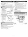
10. Pull
outthestarter
rope
and
runitintotheeyehook
(Fig.
3).
11. Insert
theeyehookintothe
remaining
holeonthe
straight
metal
shaft
(Fig.
3).
12. Screw
thenutontotheeye
hook
(Fig3)andusea7/16"
wrench
totighten.
DONOT
OVERTIGHTEN.
13. Using
theziptiesinthe
hardware
bag,secure
the
handle
cables
tothestraight
metal shaft mid-way between
the eye hook and the motor
housing.
NOTE: DO NOT run any control
wires though the eye
hook.
14.
15.
16.
17.
Cut the Zip tie holding the
bail to the handle (Fig. 4).
Insert the Z-Hook into the
hole on the right side of the
bail to secure the clutch
cable to the bail (Fig. 4).
Remove the nut and bolt
from the throttle control
(Fig. 5).
Align the throttle control with
the hole on the right side of
the handle (Fig. 5).
Starter
4.
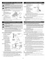
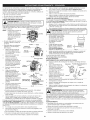
Pour the entire bottle of oil into
the oil fill hole (Fig. 7).
NOTE:
Never add oil to the fuel
or fuel tank.
Rope
Grip
5.
_/_
Wipe up any oil that may
have spilled and reinstall the
oil fill plug.
Check oil before each use and
change as needed. Refer to
Checking the Oil Level.
RECOMMENDED
FUEL TYPE
Starter
Fig. 3
Old fuel is the primary reason for
improper unit performance. Be
sure to use fresh, clean, unleaded
gasoline.
Zip Tie
Z-Hook
\
NOTE:
Control
Insert the bolt through the hole in the throttle control and the hole in the
handle.
19.
Hand-start
20.
Using a 7/16" wrench, tighten each nut onto each bolt until firm. DO
NOT OVERTIGHTEN.
_"
O-Ring
oil Fill
Hole
Fig. 8
Today's fuels are often a blend of gasoline and oxygenates such as ethanol,
methanol or MTBE (ether). Alcohol-blended fuel absorbs water. As little as 1%
water in the fuel can make fuel and oil separate or form acids when stored.
Use fresh fuel (less than 60 days old), when using alcohol-blended fuel.
Bolt
18.
oil Fill Plug
NOTE:
Fig. 4
Throttle
Fig. 7
Dispose of the old
gasoline in accordance
to Federal, State and
Local regulations.
This is a four cycle
engine. In order to avoid
damage to the unit, do
not mix oil with
gasoline.
Definition of Blended Fuels
Bail
oil Fill Hole
Using Blended Fuels
If choosing to use a blended fuel, or its use is unavoidable,
recommended precautions:
follow
,, Always use fresh unleaded gasoline
• Use the fuel additive STA-BIL® or an equivalent
• Drain tank and run the engine dry before storing unit
Using Fuel Additives
the lock-nut onto this bolt.
WARNING:
Gasoline is extremely flammable.
Ignited vapors
may explode. Always stop the engine and allow it to cool before
filling the fuel tank. Do not smoke while filling the tank. Keep
sparks and open flames at a distance from the area.
WARNING:
Add fuel in a clean, well ventilated outdoor area. Wipe
up any spilled fuel immediately. Avoid creating a source of ignition for
spilt fuel. Do not start the engine until fuel vapors dissipate.
The use of fuel additives, such as STA-BIL® Gas Stabilizer or an equivalent, will
inhibit corrosion and minimize the formation of gum deposits. Using a fuel additive
can keep fuel from forming harmful deposits in the carburetor for up to six (6)
months. Add 0.8 oz. (23 ml.) of fuel additive per gallon of fuel according to the
instructions on the fuel additive container. NEVER add fuel additives directly to the
unit's gas tank.
FUELING THE UNIT
SERIOUS PERSONAL INJURY. Check and maintain the proper oil
level in the crankcase; it is important and cannot be
overemphasized.
Check the oilOIL
before
each use and
ARNING: OVERFILLING
CRANKCASE
MAYchange
CAUSE it as
needed. See Changing the Oil.
_[
RECOMMENDED
OiL TYPE
Using the proper type and weight of oil in the crankcase is extremely important.
Check the oil before each use and change the oil regularly. Failure to use the
correct oil, or using dirty oil, can cause premature engine wear and failure.
Use a high-quality SAE 30 weight oil of API (American Petroleum Institute)
service class SF, SG, SH.
ADDING OiL TO CRANKCASE:
INITIAL USE
NOTE:
This unit is shipped
without oil. In order to
avoid damage to the
unit, put oil in the
crankcase before
attempting to start the
unit.
2.
Unscrew the top of the bottle of oil and remove the paper seal covering
the opening. Replace the top. Next, cut the tip off the funnel spout (Fig. 6).
Place unit on a flat, level surface.
3.
Remove the oil fill plug from the crankcase (Fig. 8).
spray.
Never operate
the fuel
unit cap
without
capinjury
securely
place.
WARNING:
Remove
slowlythetofuel
avoid
from infuel
_L_
been proven that fuel containing greater than 15% ethanol will
WARNING:
DO engine
NOT USE
IN THIS UNIT. It has
likely
damage this
and E85
void FUEL
the warranty.
1.
Remove the fuel cap (Fig. 9).
Gas Can
Spout
2.
Place the gas container's
spout into the fill hole on the
fuel tank (Fig. 9) and fill the
tank.
NOTE:
Do not overfill the tank.
The unit is supplied with one 3.04
fluid oz. (90 ml.) bottle of SAE 30
SF, SG, SH oil (Fig. 4).
Fig. 6
NOTE:
Save the bottle of oil. It
can be used to measure the correct amount during future oil
changes. See Changing the Oil.
1.
_
5
3.
Wipe up any gasoline that
may have spilled.
4.
Reinstall the fuel cap.
5.
Move the unit at least 30 ft.
(9.1 m) from the fueling
source and site before
starting the engine.
O
Fuel Tank
Fig. 9
m
i iwA°.,°o
o0eratethisunitonyinawe
ventiatedoutdoorarea
Carbon monox de exhaust fumes can be ethan
a conf ned area.
NOTE=
starting position when pulling the starter rope (Fig. 12). To avoid serious
ARNING:
Avoid accidental starting. Make sure to be in the
injury, the operator and unit must be in a stable position while starting, j
_
NOTE:
This unit uses the Incredi-PuIF M starting system, which
significantly reduces the effort required to start the engine. There is
no harsh resistance when pulling the starter rope. Be aware that
this starting method is vastly different from (and much easier than)
previous starting techniques.
1.
Check the oil level in the
crankcase. Refer to
Checking the Oil Level.
STARTING
2.
Fill the INSTRUCTIONS
fuel tank with fresh,
Control
F__Throttle
_
This Unit Can Use a Plug-in Power Start or Power Bit Start
Optional Accessory!
Please refer to the Plug-In Power Start or Power Bit Start operator's
manual for proper use of these features. (Items may be Sold
Separately! Please refer to page 9 of this manual for more information
about purchasing these accessories.)
STARTING INSTRUCTIONS
1.
Check the oil level in the crankcase. Refer to Checking the Oil Level.
2.
Fill the fuel tank with fresh, clean unleaded gasoline. Refer to Fueling the Unit.
NOTE:
There is no need to turn the unit on. The On/Off Control is in the
ON (I) position at all times (Fig. 10).
IF COLD... For cold weather conditions (below 40°F), flip the Cold Weather
Start Lever (Fig. 9) down to the start/closed position and continue to
step 3. DO NOT flip this lever down if the temperature is above 40°R
3.
Refer to Fueling the Unit.
NOTE:cleanThere
is no need
to turn
unleaded
gasoline.
the unit on. The On/Off
Control is in the ON (1}
position at all times
(Fig. 10).
IF COLD... For cold weather
conditions (below 40°F),
flip the Cold Weather Start
Slow
_,
\
On/Off
Control
_--4.
_'_k--'_
5.
Place the electric starter or power start bit into the back of the unit.
Refer to the Operation section of the Electric Starter or Power Start Bit
operator's manual.
6.
Press and hold the electric starter or drill ON (I) button for 2 seconds
intervals until unit starts.
Fig. 10
Cold Weather
Starter Lever
Primer Bulb
Fully press and release the primer bulb 10 times, slowly. Some amount
of fuel should be visible in the primer bulb (Fig. 11). If fuel can not be
seen in the bulb, press and release the bulb until fuel is visible.
Make sure the throttle control (Fig. 11) is in the SLOW (_)
position.
NOTE:
closed position and
continue to step 3. DO
NOT flip this lever back if
the temperature is above
40°E
3.
4.
5.
back to
Fully Lever
press(Fig.
and 11)
release
thethe
primer bulb 10 times, slowly.
Some amount of fuel should
be visible in the primer bulb
(Fig. 11). If fuel can not be
seen in the bulb, press and
release the bulb until fuel is
visible.
Stand in the starting position
(Fig. 12) and make sure the
throttle control (Fig. 10) is in
the SLOW (_)
position.
DO NOT engage the bail while starting the unit (Fig. 12) or the unit
will not start.
IF COLD... For cold weather conditions (below 40°F), flip the Cold Weather
Start Lever forward to the open position after the unit has started
and before squeezing the throttle control.
6.
Once the unit is started, remove the electric starter or drill and wait 60
seconds.
7.
From the operator's position, move the throttle control to the FAST (_')
position and allow the engine to warm up for 30 to 60 seconds (Fig. 10).
The unit may be used during this time.
_
Open _
Closed
Fig. 11
Starting
Position
IF,..
The engine does not start, go back to step 3.
IF,..
The engine stops while squeezing the throttle, go back to step 4.
STOPPING INSTRUCTIONS
1.
2.
Starter
Rope
Release the throttle control and allow the engine to cool down by idling.
Press and hold the On/Off Control in the OFF (O) position until the unit
comes to a complete stop. (Fig. 10)
Pull the starter rope in a
controlled motion 3 to 5
times or until unit starts.
NOTE:
DO NOT engage the bail
while pulling the starter
rope (Fig. 12) or the unit
will not start.
_
_ _ o
Fig. 12
HOLDING THE UNIT
-_
to ARNING:
reduce the risk
of injury
this and
unit.body protection
Always
wearwhen
eye, operating
hearing, foot
IF COLD... For cold weather conditions (below 40°F), flip the Cold Weather
Start Lever forward to the open position after the unit has started
and before increasing the throttle.
6.
Wait 60 seconds and then move the throttle control to the FAST (_)
position and allow the engine to warm up for 30 to 60 seconds. The unit
may be used during this time.
IF...
The engine does not start, go back to step 3.
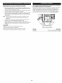
Before operating the unit, stand in the
operating position (Fig. 13). Check for the
following:
• The operator is wearing eye protection and
proper clothing.
Both hands are holding the handle bar
firmly.
IF...
The engine stops while squeezing the throttle, go back to step 4.
STOPPING INSTRUCTIONS
The edger wheel adjusted for proper cut
depth as shown in Figure 14 and edger
positioned as shown in Figure 13.
ADJUSTING EDGER CUTTING DEPTH
1.
Release the throttle control and allow the engine to cool down by idling.
2.
Press and hold the On/Off Control in the OFF (O) position until the unit
comes to a complete stop. (Fig. 10)
1.
2.
3.
Grasp the depth adjustment
located beside the front
Fig. 13
lever
wheel (Fig 14).
L_
To raise the cutting blade,
\\_
move the lever toward the
front of the wheel bracket
_X_/" _
(Fig. 14). Lowering the wheel b-_\\\\_-_
decreases the cutting depth.._9).._L
To lower the cutting blade,
_
,d_.
move the lever toward the
rear of the wheel bracket.
Raising the wheel increases
the cutting depth.
i
_
T[lurnb Wheel
Wheel Bracket
Fig. 14
Ju_tvPe_mhr
ent
TIPS FOR BEST EDGING RESULTS
• Do not force the edger. Edge
the first time at a lesser
depth,(No more than 1/2" depth
cut per pass), then do the area
again with a deeper setting.
CHECKING
BLADE EDGE
_lb[_
heochec
Wear Limit Holes
Fig. 15
If blade fails to turn when the bail is pulled, then:
1.
Locate small thumb wheel on top of the belt housing (Fig. 14).
2.
Turn the wheel clockwise 1 revolution to increase the tension on the belt.
Try pulling the bail and see if the blade turns.
the blade turns.
1.
Stop the engine and allow oil
to drain into the crankcase.
2.
Place unit on a flat, level
surface.
3.
Keep dirt, grass clippings
and other debris out of the
engine. Clean the area
around the dipstick before
removing it.
4.
5.
If not, repeat step 2 until
6.
MAINTENANCE
-I ,tk
SCHEDULE
I WARNING:
unitARNING:
off and allow
to cool
beforepersonal
cleaninginjury,
or maintaining
To itavoid
serious
always turnit.the
maintaining the proper oil level in
the crankcase cannot be
overemphasized. Check oil before
each use:
• Walk the edger at a slow, even
pace.
Check the blade condition. As
it wears it becomes smaller,
thus reducing the cutting depth
performance.
Replace with a
new blade when the blade has
worn to the blade's wear limit
holes (Fig. 15).
ADJUST BELT TENSION
3.
THE OiL LEVEL
To prevent serious injury, never perform maintenance
or repairs with unit running. Always service and repair a cool unit.
]
Remove the oil fill plug.
Look into the oil fill hole, use
a flashlight if needed. The oil
should be just touching the
inner most thread (Fig. 18).
--
oil Max Fill Line
Fig. 18
oil Fill Plug
O-Ring
If the oil level is not touching
Oil Fifl
the inner most thread on the
Hole
oil fill hole, add a small
amount of oil to the oil fill hole
and recheck (Fig. 21). Repeat
Fig. 19
this procedure until the oil level reaches the inner most thread on the oil fill
hole.
Perform these required maintenance procedures at the frequency stated in
the table. These procedures should also be a part of any seasonal tune-up.
NOTE:
NOTE:
Some maintenance procedures may require special tools or skills. If
unsure about these procedures take the unit to Sears or other qualified
service dealer. Call 1-800-4-MY=HOME® for more information.
NOTE:
Make sure the O-ring is in place on the oil fill plug when checking
and changing the oil (Fig. 19).
CHANGING THE OIL
NOTE:
Maintenance, replacement, or repair of the emission control devices
and system may be performed by a Sears or other qualified service
dealer. Call 1-800-4-MY-HOME® for more information.
_[_
FREQUENCY
MAINTENANCE
Every 10 hours
Clean air filter
p. 8
At 10 hours
Change oil
Check rocker arm to valve clearance and adjust
p. 7
p. 8
Check spark plug condition
p. 9
Every 40
REQUIRED
SEE
and gap
Change oil
p. 7
Check rocker arm to valve clearance and adjust
Check spark plug condition and gap
p. 8
p. 9
Clean spark arrestor
p. 9
BLADE REPLACEMENT
1.
Place the 5/16" Allen wrench
in the spindle hole (Fig. 16).
2.
While holding the Allen
wrench in place, loosen the
nut with a 15/16" wrench by
turning it counterclockwise
(Fig. 16).
3.
Remove the nut and blade.
Keep the nut for new blade
installation.
4.
Install the new blade and nut
(Fig. 17).
Spindle
Fig. 16
Edger
Blade
5.
While holding the Allen
wrench in the spindle hole,
tighten the nut by turning the
wrench clockwise until tight
(Fig. 16).
NOTE:
Make sure that the blade
stays flat and centered
against the output shaft
throughout installation.
Fig. 17
--
Do not overfill the unit.
CAUTION:
Wear gloves to prevent injury when handling the unit.
For a new engine, change the oil
after the first 10 hours of
operation. Change the oil while
the engine is still warm. The oil will
flow freely and carry away more
impurities.
1.
2.
Remove the oil fill plug.
Pour the oil out of the oil fill
hole and into a container by
tipping the unit to a vertical
position (Fig. 20). Allow
ample time for complete
drainage.
Wipe up any oil residue on
the unit and clean up any oil
that may have spilled.
Dispose of the oil according
to Federal, State and local
regulations.
4.
Refill the crankcase with
3.04 fl.oz. (90 ml) of SAE 30
SF, SG, SH oil.
NOTE:
Use the bottle and
spout saved from initial
use to measure the
correct amount of oil.
The top of the label on
the bottle measures
approximately 3.04 fl.oz.
(90 ml) (Fig. 22). Check
the level, See Checking
the Oil Level. If the level
is low, add a small
amount of oil and recheck.
Fig. 20
3.
5.
Replace the oil fill plug.
6.
Reconnect the spark plug boot.
Fig. 21
A
Fill Line __._
p--q
Fig. 22
Do not overfill (Fig. 18).
i
AiR FILTER MAINTENANCE
-_L_
unitARNING:
off and allow
to cool
beforepersonal
cleaninginjury,
or maintaining
To itavoid
serious
always turnit. the
Cleaning the Air Filter
Clean and re-oil the air filter every
Air Filter Cover
"_
Slot
10 hours of operation. It is an
important item to maintain. Failure
to maintain the air filter properly
can result in poor performance or
can cause permanent damage to
the engine.
1.
Open the air filter cover. Push
the tab on the left side of the
cover in, swing the air filter
cover out, and off the air filter
housing (Fig. 23).
2.
Remove the air filter (Fig. 23).
3.
Wash the filter in detergent
and water (Fig. 24). Rinse the
filter thoroughly and allow it
to dry.
4.
Apply enough clean SAE 30
motor oil to lightly coat the
filter (Fig. 25).
5.
Squeeze the filter to spread
and remove excess oil (Fig. 26).
6.
Replace the filter (Fig. 23).
j
NOTE:
The cutting attachment should not rotate when the engine idles.
3.
If the cutting attachment rotates when the engine idles, turn the idle
speed screw counterclockwise
1/8 of a turn at a time (as needed), to
reduce idle speed.
Checking the fuel, cleaning the air filter, and adjusting the idle speed should
solve most engine problems. If not and any of the following are true have the
unit serviced by a Sears or other qualified service dealer:
• the engine will not idle
the engine hesitates or stalls on acceleration
there is a loss of engine power
ROCKER ARM CLEARANCE
Tab
Hooks
Air Filter
m
_
U
This requires disassembly of the engine. If unsure or unqualified to perform this,
take the unit to a Sears or other qualified service dealer.
NOTE:
Inspect the valve to rocker arm clearance with a feeler gauge after
the first 10 hours of
operation and every 40
hours of operation.
The engine must be cold when
checking or adjusting the valve
clearance.
Fig. 24
Operating the unit
without the air filter, will
VOID the warranty.
7.
Reinstall the air filter cover.
Position the tabs on the
sides of the air filter cover
onto the slots at the top of
the back plate (Fig. 23).
8.
Push the cover in until the tab
on the air filter backplate
snaps into place in the slot on
the air filter cover (Fig. 23).
iDLE SPEED ADJUSTMENT
unitARNING:
off and allow
to cool
beforepersonal
cleaninginjury,
or maintaining
To itavoid
serious
always turnit. the
Fig. 23
NOTE:
1.
Remove the six (6) screws on
the back of the engine cover
with a Flat-head or T-25 Torx
screwdriver (Fig. 28).
2.
3.
Disconnect the spark plug wire.
Clean dirt from around the
spark plug. Remove the spark
plug from the cylinder head by
turning a 5/8 in. socket
counterclockwise.
Fig. 25
4.
6.
• The piston is at the top of its
travel. This should be done by
looking into the spark plug hole.
(Fig. 30)
Fuel
Old fuel is usually the reason for improper unit performance. Drain and refill the tank
with fresh fuel prior to making any adjustments. Refer to Oil and Fuel Information.
Second, Clean Air Filter
The condition of the air filter is important to the operation of the unit. A dirty
air filter will restrict air flow. This is often mistaken for an out of adjustment
carburetor. Check the condition of the air filter before adjusting the idle
speed screw. Refer to Air Filter Maintenance.
Third, Adjust Idle Speed Screw
adjustments. Wear protective clothing and observe all safety
instructions to prevent serious personal injury.
If, after checking the fuel and
cleaning the air filter, the engine
still will not idle, adjust the idle
speed screw as follows:
2.
Pull the starter rope slowly to
bring the piston to the top of
its travel, (known as top dead
center). Check that:
Careless adjustments can seriously damage the unit. Aside from
idle speed, only a Sears or other qualified service dealer should
make carburetor adjustments.
First, Check
1.
Remove the engine cover
(Fig. 28).
Clean dirt from around the
rocker arm cover. Remove the
screw holding the rocker arm
cover with a large flat blade
screwdriver or Torx T-25 bit
(Fig. 29). Remove the rocker
arm cover and gasket.
5.
Fig. 26
Idle Adjustment
Screw
Start the engine and let it run
at a high idle for a minute to
warm up. Refer to
Starting/Stopping
Instructions.
Release the throttle trigger
and let the engine idle. If the
Fig. 27
engine stops, insert a small phillips in between the Air Filter Cover and
the Engine Cover (Fig. 27). Turn the idle speed screw in, clockwise, 1/8
of a turn at a time (as needed) until the engine idles smoothly.
of the
Rear
Engine
Cover
Screws
Screws
This task should be performed
inside, in a clean, dust free area.
NOTE:
The idle speed of the engine is
adjustable. An idle adjustment
screw is between the air filter
cover and the engine starter
housing (Fig. 27).
View
and both valves are closed
If these statements are not true,
repeat step 6.
Both the
rocker
arms
move
freely,
7.
Slide
feeler
gauge
between
the rocker arm and the valve
Rocker Arm
Cover
Spark Plug
Hole
Fig. 29
Adjusting
Nuts
INTAKE
EXHAUST
Rocker
Arms
Fig. 30
Exhaust
Adjusting
Nut
Rocker Arm
____
/
_
--
n._o
Feeler
Gauge
0.003-0.006 i
(0.076-0.152 ram)
L.
return spring. Measure the
Fig. 31
clearance between the valve
stem and rocker arm (Fig. 31). Measure both the intake and exhaust valves.
The recommended clearance for both intake and exhaust is .003 - .006 in.
(.076 - 0.152 rnrn). Use a standard automotive .005 in. (0.127 mm) feeler
gauge. The feeler gauge should slide between the rocker arm and valve stem
with a slight amount of resistance, without binding. See Figures 30 and 31.
8. If the clearance is not within specification:
a.
Turn the adjusting nut using a 5/16 inch (8 mm) wrench or nut driver
(Fig. 31).
To increase clearance, turn the adjusting nut counterclockwise.
b.
To decrease clearance, turn the adjusting nut clockwise.
Recheck both clearances, and adjust as necessary.
9.
Reinstall the rocker arm cover using a new gasket. Torque the screw to
20-30 inolb (2.2-3.4 Norn).
10.
Check the spark plug and reinstall. See Replacing the Spark Plug.
11.
Replace the spark plug wire.
12. Reinstall
theengine
cover.
Check
alignment
ofthecover
before
tightening
thescrews.
Tighten
screws.
REPLACING
THESPARK
PLUG
Useareplacement
Champion
®#RDZ4N
sparkplug.Thecorrect
airgap
is0.025
in.{0.635 rnrn). Remove the plug after every 40 hours of operation
1.
Drain all gasoline from the gas tank into a container. Do not use gas
that has been stored for more than 60 days. Dispose of the old gasoline
in accordance to Federal, State, and Local regulations.
2.
Start the engine and allow it to run until it stalls. This ensures that all
gasoline has been drained from the carburetor.
1.
3.
Allow the engine to cool. Remove the spark plug and put 5 drops of
high quality motor oil into the cylinder. Pull the starter rope slowly to
distribute the oil. Reinstall the spark plug.
LONG TERM STORAGE
and check its condition.
Stop the engine and allow it to cool. Remove the six (6) screws on the back
of the engine cover with a Flat-head or T-25 Torx screwdriver (Fig. 28).
Grasp the plug wire firmly and pull the cap from the spark plug.
2.
-A
3.
I WARNING:
e ectrodes.
Do not sand blast, scrape or clean spark plug
the engine could damage the cylinder.
Gr t n
]
Clean dirt from around the
Replace cracked, fouled or
dirty spark plug. Set the air
gap at 0.025 in. {0.635 rnrn)
using a feeler gauge (Fig. 32).
5.
Install a correctly-gapped
spark plug in the cylinder
head. Turn the 5/8 in. socket
clockwise until snug.
4.
Remove the spark plug and drain all of the oil from the cylinder
before attempting to start the trimmer after storage.
Change the oil, referring to Changing the Oil. Dispose of the old oil in
accordance to Federal, State and Local regulations.
5.
Thoroughly clean the unit and inspect for any loose or damaged parts.
Repair or replace damaged parts and tighten loose screws, nuts or
bolts. The unit is ready for storage.
TRANSPORTING
spark plug. Remove the spark
plug from the cylinder head by
turning a 5/8 in. socket
counterclockwise.
4.
NOTE:
Allow the engine to cool before transporting.
Secure the unit while transporting.
0.025 in.
(0.635 ram)
Drain the gas tank before transporting.
Tighten gas cap before transporting.
J_
t
Fig. 32
If using a torque wrench torque to: 110=120 in.olb. (12.3=13.5 Norn)
PLUG-IN POWER START AND POWER BIT START FEATURES
Do not over=tighten.
SPARK ARRESTOR
This unit is designed to be started with an optional Plug-In Power Start or
Power Bit Start that are sold separately. If choosing to start the unit using
one of these features or have questions please contact your local retailer or
call 1-800-4-MY-HOME®,
for more information and purchasing. You may
also go to www.craftsrnan.com.
MAINTENANCE
1.
2.
Remove the rear engine cover. See Rocker Arm Clearance.
With a flat blade screwdriver or Torx T-20 bit and a T-25 bit, remove the
screws attaching the spark arrestor cover to the muffler (Fig. 33).
3.
Pull the tab on the spark
arrestor cover out of the
Muffler
Spark Arrestor
Screen
arrestor cover.
4.
Cover
Remove the spark arrestor
screen from the spark
arrestor cover.
muffler. Remove the spark
5.
_
[_
Clean the
arrestor
screen
withspark
a wire
brush or
replace it.
--
_"
1"-20Screw _
Reinstall the spark arrestor
screen, spark arrestor cover
and screws.
CLEANING
I WARNING:
_ /
_
Slot
6.
I A
T-25
Screw
JZ
Fig. 33
To avoid serious personal injury, always turn the
unit off and allow it to cool before cleaning or maintaining
it.
i
Electric
item No.
316.85951
316.85952
Use a small brush to clean off the outside of the unit. Do not use strong
detergents. Household cleaners that contain aromatic oils such as pine and
lemon, and solvents such as kerosene, can damage plastic housing or handle.
Wipe off any moisture with a soft cloth.
STORAGE
Never store the unit with fuel in the tank where fumes may reach an open
flame or spark.
Allow the engine to cool before storing.
Lock up the unit to prevent unauthorized
use or damage.
Store the unit in a dry, well-ventilated area.
Store the unit out of the reach of children.
9
.....................................
........................................
Start
Feature
Description
Plug-In Power Start
Power Bit Start
PROBLEM
SOLUTION
Fill fuel tank with fuel
Empty fuel tank
Pdmer bulb wasr,t
Press primer bulb fully and Slowly i0 times
Piessed enough
Old fuel
Drain gas tank and add fresh fuel
H
Fou ed spark pug
Rep ace or c ean the spark pug
Plugged spark arrestor
Clean or replace spark arrestor
iiii_
....
Air filter is plugged
Replace or clean the air filter
Old fuei
Drain
gas tank and add fiesh
Improper idle speed
Adjust according
Old fuel
Drain gas tank and add fresh fuel
Improper
carburetor
Take
adjustment
to the Idle Speed Adjustments
section.
to sears or other qualified Service dea!ei f0r an adjustment
Blade bound with dirt or grass
Stop the engine and clean the blade
Dirty air filter
Clean or replace the air filter
Plugged spark arrestor
Clean or replace spark arrestor
I
Old fuel
Impropei carburetor
Drain gas tank and add fresh fuel
adjustment
Take to sears oi other qualified Seivice dealei for an adjustment
Fouled spark plug
Plugged
spark
arrestor
Replace or clean the spark plug
' Clean
orreplace
spark
arrestor
10
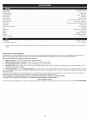
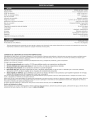
Engine Type ....................................................................................................
Air-Cooled, 4-Cycle
Displacement .....................................................................................................
Operating RPM ........................................................................................................
1.8 cu. in. (29 cc)
6,800+ rpm
Idle Speed RPM ..................................................................................................
2,800 - 3,600 rpm
Ignition Type ............................................................................................................
Ignition Switch ......................................................................................................
Electronic
Rocker Switch
Valve clearance ......................................................................................
0.003-0.006
Spark Plug Gap ...............................................................................................
in. (0.076-0.152
Spark Plug ........................................................................................
Lubrication ............................................................................................................
Champion
RDZ4H or equivalent plug
SAE 30 Oil
Crankcase Oil Capacity ...............................................................................................
Fuel ..................................................................................................................
3.04 oz (90 ml)
Unleaded
Carburetor ..................................................................................................
Starter ..............................................................................................................
Muffler
Diaphragm, All-Position
Auto Rewind
.........................................................................................................
Baffled with Guard
Throttle ......................................................................................................
Fuel Tank Capacity
Manual Spring Return
...................................................................................................
14 oz (414 ml)
Unit Weight ....................................................................................................
22.1 Ibs. (10.02 kg.)
Cutting Depth (maximum) ...........................................................................................
*
All specifications
notice.
are based on the latest product information
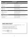
REPAIR PROTECTION
1.75 in. (44.5 mm)
available at the time of printing. We reserve the right to make changes at any time without
AGREEMENTS
Congratulations on making a smart purchase. Your new Craftsman <+product is designed and manufactured for years of dependable operation.
products, it may require repair from time to time. That's when having a Repair Protection Agreement can save you money and aggravation.
Here is what the Repair Protection
[]
Expert
service
[]
Unlimited
[]
Product
[]
Discount
preventive
mm)
0.025 inch (0.635 mm)
by our 10,000
service
Plan Agreement
professional
and no charge
replacement
of 10% from
maintenance
up to $1500
for parts
if your
But like all
includes:
repair
specialists
and labor
covered
regular price of service
checks
on all covered
product
and related
repairs
can not be fixed
installed
parts not covered
by the agreement;
also,
10% off regular
price of
[]
Fast help by phone - we call it Rapid Resolution
- phone support
from a Sears representative.
Think of us as a "talking owner's manual."
Once you purchase the Agreement, a simple phone call is all that it takes for you to schedule service. You can call anytime day or night, or schedule a service
appointment online.
The Repair Protection Agreement is a risk-free purchase. If you cancel for any reason during the product warranty period, we will provide a full refund. Or a prorated
refund anytime after the product warranty period expires. Purchase you Repair Protection Agreement today!
Some limitations and exclusions apply. For prices and additional information in the U.S.A. call 1=800=827=6655.
*Coverage
in Canada varies
on some items. For full details call Sears Canada at 1-800-361-6665.
Sears Installation Service
For Sears professional installation of home appliances, garage door openers, water heaters, and other major home items, in the U.S.A. or Canada call 1-800-4-MY-HOME®.
11
12
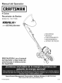
Manual del Operador
M
4 Ciclos
Recortador
de Bordes
Modelo No. 316.772380
INCREDI.PULL_
TM
UNBELIEVABLE
with
MAX
STARTING
EA S E
FIRE_._IGNITION
_
*
*
*
*
*
PRECAUCiON:
del operador
SEGURIDAD
MONTAJE
FUNCIONAMIENTO
MANTENIMIENTO
LISTADO DE PIEZAS
Lea el manual
y siga todas
las
advertencias
e instrucciones
de seguridad.
Sears Brands
Management
Visite
P/N 769=05248 PO0
Corporation,
nuestro
Hoffman
Estates,
IL 60179 U.S.A.
sitio web: www.craftsman.com
11/09
PROPOSICION
65 DE CALiFORNiA
Toda la informaci6n, las ilustraciones y las especificaciones contenidas en este
manual se basan en la informaci6n mAs reciente disponible en el momento de
impresi6n del manual. Nos reservamos el derecho de hacer cambios en
cualquier momento sin aviso previo.
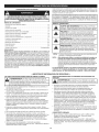
Los simbolos de seguridad se utilizan para Ilamar su atenci6n sobre posibles peligros. I
Los simbolos de seguridad y sus explicaciones merecen toda su atenci6n y_
comprensi6n. Los simbolos de seguridad no eliminan ningL_npeligro pot si mismos.
Las instrucciones o advertencias que ofrecen no substituyen las medidas adecuadas
de prevenci6n de accidentes.
J
LAS EMISIONES DEL MOTOR DE ESTE PRODUCTO CONTIENEN
SUBSTANCIAS QUIMICAS QUE EL ESTADO DE CALiFORNiA CONOCE
COMO CAUSANTES DECANCER, DEFECTOS DE NACIMIENTO U OTROS
DANOS REPRODUCTIVOS.
INDICE DE CONTENIDOS
SIMBOLO
Normas para una operaci6n segura ..............................
Garantia ...................................................
14
16
Conozca su unidad ...........................................
Instrucciones de ensamble .....................................
16
16
Informaci6n
17
del aceite y del combustible
..........................
Instrucciones
de arranque y apagado
Instrucciones
Instrucciones
de operaci6n
....................................
de mantenimiento y reparaci6n ......................
Limpieza y almacenamiento
............................
precauci6n. DE
DebeSEGURIDAD:
prestar atenci6n
ALERTA
para
evitar
sufrir advertencia
graves lesiones
Indica
peligro,
o
personales. Puede ser utilizado junto con otros simbolos o figuras.
puede
que
usted u otras
personas sufran
graves
PELIG conducir
RO: Elano
obedecer
una advertencia
de seguridad
lesiones. Siga siempre las precauciones de seguridad para reducir
el riesgo de incendio, descarga el6ctrica y lesiones personales.
18
19
19
....................................
21
Accesrorio Opcional ..........................................
Resoluci6n de problemas ......................................
22
23
Especificaciones
.............................................
24
Lista de piezas ..............................................
Numeros de servicio ................................
24
Contraportada
puede conducir a que
ADVERTENOIA:
usted
u otrasuna
personas
sufrandelesiones.
El
no seguir
advertencia
seguridad
Siga siempre las precauciones de seguridad para reducir el
riesgo de incendio, descarga el6ctrica y lesiones personales.
_,
PRECAUCION:
El no seguir una advertencia de seguridad
puede conducir a daSo patrimonial o a que usted u otras personas
sufran lesiones personales. Siga siempre las precauciones de
seguridad para reducir el riesgo de incendio, descarga el6ctrica y
lesiones personales.
PARACNISPAS
NOTA: Para los usuarios en tierras forestales de los EE.UU. yen los estados de
California, Maine, Oregon y Washington. Todos los terrenes forestales de los EE.UU.
y el estado de California (C6digos de Recursos PQblicos 4442 y 4443), Oregon y
Washington, requieren pot decreto, que ciertos motores de combusti6n interna que se
hagan funcionar en zonas boscosas y/o zonas cubiertas por pastizales, esten equipados
con un parachispas, que sean mantenidos en buen estado de funcionamiento o que el
motor sea construido, este equipado y sea mantenido para evitar incendios. Consulte los
reglamentos pertinentes a esos requisitos con las autoridades estatales o locales. El
incumplimiento de esos requisitos puede responsabilizarleo someterle a la imposici6n de
una multa. Esta unidad fue equipada en la fabrica con un parachispas. Si requiere
sustituci6n, hay una Pantalla Parachispas disponible, Pieza # 753-05245 al contactar el
departamento de servicio.
• IMPORTANTE
NOTA:
Le ofrece informaci6n o instrucciones que son esenciales para la
operaci6n o mantenimiento del equipo.
NOTA:
iEsta unidad puede utilizar un comienzo enchufable de la energia o un
accesorio de arranque opcional comienzo del pedacito de energfa!
Para informarse sobre el use adecuado de estos sistemas, consulte el
manual del operador del comienzo enchufable de la energia de opcional
comienzo del pedacito de energia. (Se vende por separado) En la pagina 22
de este manual encontrara la informaci6n necesaria para comprar estos
accesorios).
Lea el manual del operador y siga todas las advertencias e instrucciones de
seguridad. De no hacerlo, el operador y/o los espectadores pueden sufrir
graves lesiones. Sl TIENE PREGUNTAS, LLAME AL 1=800=4=MY=HOME®
INFORMACION
ANTES DE OPERAR LA UNIDAD
DE SEGURIDAD
•
AVlSOS DE SEGURIDAD PARA LAS UNIDADES QUE FUNCIONAN CON
GASOMNA
R
LEA TODAS LAS INSTRUCCIONES
SIGNIFICADO
[_J
A
seguridad cuando use la unidad. Por favor lea estas instrucciones
para su propia seguridad y las de los espectadores, antes de
hacer
funcionar la unidad.
Por favor
estas reglas
instrucciones
DVERTENCIA:
Se deben
seguirmantenga
las siguientes
de
en un lugar seguro para uso futuro.
• Lea las instrucciones cuidadosamente.
uso adecuado de la unidad.
_J_
I ADVERTENClA:
La gasolina es muy infiamable y sus gases
Almacene el combustible solamente en recipientes dise_ados y aprobados
especificamente para el almacenamiento de dichos materiales.
Familiaricese con los controles y el
•
• No opere esta unidad cuando est6 cansado, enfermo o bajo la infiuencia de
alcohol, drogas o medicamentos.
• Los niSos y los adolescentes menores de 15 a5os de edad no deben usar la
unidad. Los adolescentes pueden hacerlo bajo la supervisi6n de un adulto.
Evite crear una fuente de ignici6n para el combustible derramado. No
arranque el motor hasta que se disipen los vapores del combustible.
Todos los dispositivos de protecci6n y los accesorios de seguridad deben
estar instalados adecuadamente antes de operar la unidad.
Pare siempre el motor y deje que se enfrie antes de Ilenar el tanque de
combustible. Nunca quite la tapa del tanque de combustible, ni agregue
combustible, cuando el motor est6 caliente. Nunca opere la unidad sin la
tapa de combustible bien colocada en su lugar. Afioje la tapa del tanque de
combustible lentamente para aliviar cualquier presi6n que haya en el tanque.
Inspeccione la unidad antes de usarla. Reemplace las piezas daSadas.
Verifique si hay fugas de combustible. AsegQrese de que todos los fijadores
est6n en su lugar y asegurados. Reemplace las piezas que est6n agrietadas,
astilladas o da5adas en cualquier forma. No opere la unidad con piezas
sueltas o daSadas.
Agregue el combustible en un Area exterior bien ventilada, donde no haya
chispas ni llamas. Quite lentamente la tapa de combustible s61o despues de
haber parado el motor. No fume mientras est6 Ilenando de combustible o
mezclandolo. Limpie de la unidad inmediatamente cualquier combustible
derramado. Seque siempre la unidad antes de usarla.
Inspeccione cuidadosamente el Area antes de operar la unidad. Elimine
todos los escombros y los objetos duros o filosos tales como cristal, alambre,
etc.
Mueva siempre la unida a 30 pies (9.1 m) como minimo de la fuente y sitio de
combustible antes de arrancar el motor. No fume ni permita chispas ni llamas
expuestas cerca del Area mientras est6 agregando combustible u operando
la unidad.
Est6 consciente del riesgo de lesi6n en la cabeza, las manos y los pies.
CUANDO ESTI_ OPERANDO
No permita niSos, espectadores ni mascotas en el Area. Los niSos, los
espectadores y las mascotas deben estar fuera de un radio de 50 pies (15 m.)
como minimo; de todas formas los espectadores correran el riesgo de ser
golpeados por objetos lanzados por la unidad. Se debe exhortar a los
espectadores a que usen protecci6n para los ojos. Si se le acerca alguien
apague la unidad de inmediato.
Oprima el control del estrangulador y compruebe que regresa
automaticamente a la posici6n de marcha en vacio. Haga todos los ajustes o
reparaciones antes de usar la unidad.
14
i
pueden exp otar s se enc enden. Tome as s gu entes precauc ones: |J
.
Nunca arranque ni opere la unidad dentro de un cuarto o edificio cerrado.
Respirar los vapores del escape puede ser fatal. Opere esta unidad
solamente en un Area exterior bien ventilada.
.
Use galas protectoras que cumplan con la norma Z87.1-1989 de ANSI y
tengan la marca que Io indica. Use protecci6n para la oreja/audici6n cuando
opere esta unidad. Use mascara facial o para polvo si la operaci6n produce
mucho polvo.
• Use pantalones largos fuertes, botas, guantes y camisa de mangas largas. No
use ropa holgada, joyas, pantalones cortos, sandalias, ni est6 descalzo.
AsegQrese el cabello por encima del nivel de los hombros.
• Esta unidad tiene un embrague. La lamina sigue siendo inm6vil cuando el
motor estA estando desocupado. Si no sucede asi, haga que un t6cnico de
servicio autorizado ajuste la unidad.
• Pare la unidad, apague el motor y desconecte la bujia para mantenimiento o
reparaci6n.
• Est6 seguro que la lamina no esta en contacto con cualquier cosa antes de
comenzar la unidad.
• Mantenga la unidad limpia de vegetaci6n y otros materiales. Pudieran quedar
obstruidas entre las pOas y el protector.
• Use la unidad solamente de dia o con buena luz artificial.
• Para reducir el peligro de incendio reemplace un silenciador y amortiguador
de chispas defectuoso. Mantenga el motor y el silenciador libre de hierba,
hojas, exceso de grasa o acumulaci6n de carb6n.
DESPUI_S DE USARLA
• Use solamente piezas y accesorios de reemplazo del fabricante del equipo
original para esta unidad. Estos estAn disponibles en su proveedor de servicio
autorizado. El uso de cualquier pieza o accesorio no autorizado podria causar
lesiones graves al usuario, o da_os a la unidad, y anular su garantia.
• Evite arranques accidentales. Est6 en la posici6n de arranque cada vez que
hale la cuerda de arranque. El operador y la unidad deben estar en una
posici6n estable al arrancar. Consulte las Instrucciones de Arranque/Parada.
• Use la herramienta correcta. Use esta herramienta solamente para el
prop6sito para el cual rue dise_ada.
• Limpie las pOas con un limpiador casero para eliminar la acumulaci6n de
resina. Engrase la lamina con aceite de la mAquina para prevenir moho.
OTROS AVlSOS DE SEGURIDAD
• Tenga mucho cuidado cuando invierta o mueva la unidad hacia usted.
• No se estire demasiado. Mantenga siempre la base de apoyo y equilibrio
adecuados. Tenga mucho cuidado cuando trabaje en pendientes marcadas o
inclinadas.
• Nunca almacene una unidad con combustible dentro de un edificio en el cual
los vapores puedan Ilegar a una llama expuesta o una chispa.
• Deje que el motor se enfrie antes de almacenarlo o transportarlo. AsegOrese
de fijar bien la unidad mientras la transporta.
• Almacene la unidad en un Area seca y cerrada, o en un lugar alto para evitar
uso no autorizado o da_os. Mant6ngala alejada del alcance de los ni_os.
• Sostenga siempre la unidad con ambas manos cuando la opere. Mantenga un
agarre firme sobre ambas manijas.
• Mantenga las manos, la cara y los pies alejados de todas las partes en
movimiento. No toque ni intente parar la lamina mientras que esta girando.
• No toque el motor
operaci6n, incluso
• No opere el motor
funcionar el motor
• Nunca rocie ni chorree la unidad con agua ni ningOn otro liquido. Mantenga
las manijas secas, limpias y libres de escombros. Limpiela despues de usarla,
vea las instrucciones de Limpieza y Almacenamiento.
• Conserve estas instrucciones. ConsQItelas con frecuencia y Oselas para
instruir a otros usuarios. Si le presta esta unidad a alguien, pr6stele tambien
estas instrucciones.
o el silenciador. Estas piezas estan muy calientes durante la
despu6s de que se apaga la unidad.
a mAs velocidad de la necesaria para cultivo. No haga
a alta velocidad cuando no est6 cultivo.
• Pare siempre el motor cuando deje de cultivo o cuando est6 caminando de un
lugar de cultivo hacia otro.
GUARDE ESTAS INSTRUCCIONES
• Si golpea o se enreda con un objeto extra,o, pare el motor inmediatamente y
verifique si ha habido algQn da_o. No Io opere antes de reparar el da_o. No
opere la unidad con piezas sueltas o da_adas.
o SliVIBOLOS DE SEGURIDAD
E INTERNACIONALES
•
Este manual del operador describe los simbolos y figuras de seguridad e internacionales que pueden aparecer en este producto.
para obtener informaci6n completa acerca de la seguridad, ensamble, operaci6n y mantenimiento y reparaci6n.
SIMBOLO
SIGNIFICADO
SIMBOLO
JDAD,
_e81_:e
_re_
m
6
m
_ii_iil!iiiii!iiiiil;:i;i;ii!
i_ii
15
SIGNIFICADO
Lea el manual del operador
GARANTIA TOTAL DE CRAFTSMAN
Si este producto de Craftsman falla debido a un defecto en el material o en la mane de obra dentro de un periodo de dos aSos a partir de la fecha de compra,
devuelvalo a cualquier tienda o Centro de Servicio de Piezas y Reparaciones Sears u otro establecimiento de Craftsman en los Estados Unidos para que sea
reparado sin costo alguno (o ser reemplazado si resulta imposible repararlo).
Esta garantia se aplica solamente durante 90 dias si este producto
en algQn momento se utiliza para fines comerciales
o de alquiler.
Esta garantfa abarca SOLAMENTE los defectos en el material o en la mane de obra. Sears NO pagar_:
• Los articulos consumibles que se desgasten debido al uso normal dentro del periodo de garantia.
• Las reparaciones necesarias debidas a accidente asi como por no operar o no mantener el equipo de acuerdo con todas las instrucciones provistas.
• Mantenimiento preventivo, afinaciones del producto, o limpiezas o ajustes de carburadores.
Esta garantia le concede a usted derechos legales especificos, y usted pudiera tener otros derechos que varian de un estado a otto.
Sears, Roebuck and Co., Hoffman Estates, IL 60179
APPLICACIONES
• Para hacer recortes a Io largo de senderos, estacionamientos,
rocosos, etc.
jardincillos
Traba
Manubrio
del asa
Asa
Gatillo del
regulador
Tapa del
combustible
Tap6n del
aceite
Manija de la cuerda
de arranque
Control de encendido
y apagado
Bujia de
encendido
Cubierta
del
filtro
de aire
Silenciador
Bombilla
del
cebador
Palanca de ajuste
de profundidad
Cuchilla del
recortador de hordes
CONJUNTO
1.
2.
_,_:____
DE LA MANIJA
5.
Quite las tuercas y los
pernos de los componentes
de la manija. AsegQrese de
volver a colocarlos en los
!_
orificios de donde salieron.
Coloque el extreme de 2
orificios del eje metalico
recto sobre la base del eje
en la unidad y alinee los
orificios (Fig. 1). AsegOrese
de que la etiqueta que dice
PARA ARRANCAR (TO
START) mire hacia arriba.
[_"
II
Asidero mediano
U
Contratuereas
Pernos
%
6.
Inserte dos pernos de cabeza con reborde
orificios (Fig. 1).
4.
Coloque con las manos las contratuercas en estos pernos.
Utilizando una Ilave de 3/8",
sujete cada uno de los pernos
de cabeza con reborde y
apriete las contratuercas con
una Ilave de 7/16" hasta que
est6n firmes. NO APRIETE
DEMASlADO.
Asidero supeno_ /
Coloque el eje de la manija de
control en el extremo de 3
orificios del eje meta.lico recto y
alinee los orificios de la manija
de control con los dos orificios
Fig. 2
del extremo del eje meta.lico
recto (Fig. 2).
NOTA:
Debido a que los cables de control han sido instalados
previamente, se debera tener mucho cuidado al instalar la manija
de control a fin de no pinchar o doblar los cables. Esto puede
dafiarlos y hacer que no funcionen bien.
Asidero m_s
bajo
Fig. 1
3.
Protector
cuchilla de la
(1/4" x 1-1/4") en estos
16
2.
conreborde
(1/4"x1-1/4")
en
estos
orificios
(Fig.
1).
7. Coloque
Inserte
dos
pernos
decabeza
8.
con
lasmanos
las
contratuercas
enestos
9.
emos
Utilizando una Ilave de 3/8",
_-'_
j. lacuerda 3.
earranque 4.
_
dMango
de
_ _ Gancho
deojo
_
A \ /co° o°
Oo
NOTA:
Contratuercas
de cabeza con reborde y
sujete
uno de los pernos
apriete cada
las contratuercas
con
una Ilave de 7/16" hasta que
est6n firmes. NO APRIETE
"_"_
anque
5.
__S
Fig. 3
DEMASlADO.
10.
11.
12.
13.
Tire de la cuerda de arranque
y deslicela a trav6s del
gancho de ojo (Fig. 3).
/
Inserte el gancho de ojo en el
orificio restante en el eje
metalico recto (Fig. 3).
NOTA:
14.
15.
16.
17.
18.
Cincho de plastico
[
Verifique el aceite antes de cada
uso y cambielo cuando sea
necesario seg0n se indica en la
secci6n de Cambio del aceite.
Gancho en "Z"
l
Fig. 7
tap6n
El combustible viejo es la causa
principal del mal funcionamiento
Anillo
de la unidad. Aseg0rese de usar
combustible nuevo, limpio y sin
plomo. Elimine la gasolina vieja de
Orificio
acuerdo a los reglamentos
Henado
federales, estatales y locales.
aceite
NOTA:
Este es un motor de
cuatro ciclos. Para evitar
daSar su unidad, no
mezcle el aceite con la gasolina.
Definici6n de los combustibles
de mezcla
Estribo
arqueado
Fig. 4
Control del
regulador
/.
Perno
/
/
Tuerca
/
NO pase ningQn cable
de control a trav6s del
gancho de ojo.
de aceite
Coloque con las manos la contratuerca
20.
Utilizando una Ilave de 7/16", apriete cada una de las tuercas de cada
perno hasta que queden firmes. NO APRIETE DEMASIADO.
de
de
Fig. 8
Si decide usar un combustible de mezcla o si su uso es inevitable, le
recomendamos que tome las siguientes precauciones:
el control del regulador con el orificio del lado derecho de la
(Fig. 6).
el perno a trav6s del agujero en el control del regulador y el
en la manija.
19.
en
Los combustibles actuales con frecuencia son una mezcla de gasolina y uno o
m&s oxigenantes como el etano, el metanol o el MTBE (6ter). El combustible con
mezcla de alcohol absorbe agua. Un porcentaje de agua tan pequeSo como el
1% en el combustible puede hacer que el combustible y el aceite se separen. Se
forman &cidos mientras est& guardado. Cuando use combustible con mezcla de
alcohol, use combustible nuevo (almacenado durante menos de 60 dias).
Uso de los combustibles
de mezcla
Corte el cincho de pla.stico que
sujeta el estribo arqueado a la
Fig. 5
manija (Fig. 4).
Inserte el gancho en "Z" en el orificio del lado derecho del estribo arqueado
para asegurar el cable del embrague al estribo arqueado (Fig. 5).
Quite la tuerca y el perno del control del regulador (Fig. 6).
Alinee
manija
Inserte
orificio
No agregue nunca aceite
al combustible o al
tanque de combustible.
Limpie todo el aceite que
pueda haberse derramado y
vuelva a instalar el tap6n del
aceite.
TIPO BE COMBUSTIBLE
RECOMENDADO
Atornille la tuerca en el gancho
de ojo (Fig. 3) y utilice una Ilave
de 7/16" para apretar. NO
APRIETE DEMASIADO.
Utilizando los cinchos de
pl&stico que vienen en la
bolsa de piezas, asegure los
cables de la manija a la
mitad del eje met&lico recto
entre el gancho de ojo y la
caja del motor.
Coloque la unidad sobre una superficie plana.
Saque el tap6n de aceite/varilla de medici6n del cig0eSal (Fig. 8).
Vierta todo el contenido de
la botella de aceite en el
cig0e5al (Fig. 7).
• Use siempre una mezcla fresca de combustible segOn Io indica su manual
del operador
• Use un aditivo de combustible estabilizador de gasolina
Drene el tanque y haga funcionar el motor en seco antes de guardar la unidad
Uso de aditivos en el combustible
en este perno.
ADVERTENCIA:
La gasolina es muy inflamable. Los gases pueden
explotar si se encienden. Apague siempre el motor y espere que se enfrie
antes de cargar el tanque de combustible. No fume mientras Ilena el
tanque. Mantenga las chispas y las llamas lejos del &rea.
,_k I ADVERTENClA: EL LLENAR DEMA- SIADO EL CARTER PUEDE
I _
_ CAUSAR LESIONES PERSONALES GRAVES No podemos exagerar la
==_==' _ importancia del control y mantenimiento del nivel correcto de aceite en
el cig0ehal. Verifique el aceite antes de cada uso y c_.mbielo cuando
ADVERTENOIA:
sea necesar o segQn send ca en a secc 6n de Camb o de ace te.
TIPO DE ACEITE RECOMENDADO
El uso de un estabilizador de gasolina impedira la corrosi6n y reducir& al minimo la
formaci6n de dep6sitos de resina. El uso de aditivos puede evitar que se formen
dep6sitos dahinos en el carburador por hasta sais (6)meses. Agregue 23 ml (0,8 de
onza) de aditivo por gal6n de combustible de acuerdo alas instrucciones del envase.
No agregue NUNCA los aditivos directamente al tanque de combustible de la unidad.
El uso de un aceite del tipo y peso correctos en el cigQeSales extremadamente
importante. Verifique el aceite antes de cada uso y cambie el aceite con frecuencia.
Si no usa el aceite correcto, o utiliza aceite sucio, puede causar el desgaste y falla
prematuros del motor. Use un aceite de buena calidad SAE 30 de API (American
Petroleum Institute) clase de servicio SG, SE SH.
CARGA DE ACEITE EN EL CARTER DEL CIGOE_IAL: USO INICIAL
NOTA:
Esta unidad se envia sin carga de aceite. A fin de evitar el daSo de
la unidad, cargue aceite
en el c&rter del cigOeSal
antes de intentar
arrancar la unidad.
Su unidad trae una botella de
aceite SAE 30 SF, SG, SH de 90 ml
(3,04 onzas fluidas) (Fig. 4).
NOTA:
1.
Cargue el com-bustible en un a.reaexterior limpia
y bien ventilada. Limpie de inmediato todo combustible que se haya
derramado. Evite crear una fuente de encendido con el combustible
derramado. No arranque el motor hasta que se hayan evaporado los
gases del combustible.
Guarde la botella para
medir la cantidad correcta
de aceite cuando deba
cambiarlo en el futuro. Lea
Cambio de Aceite.
Desenrosque la tapa de la
botella de aceite y retire el sello de papel que cubre la apertura. Vuelva a
colocar la tapa. Corte la punta de la boquilla del embudo (Fig. 6).
17
CARGA DE COMBUSTIBLE
EN LA UNIDAD
NOTA:
No conecte el asa
mientras tire de la cuerda
de arranque (Fig. 12) o la
unidad no arrancar&
_
Sl ESTA FRIO... Para las
condiciones
atmosf6ricas frias
arrsnque
(debajo de 40°F), mueva
de un tir6n la palanca
del comienzo del tiempo
Cuerda
de
4 --!
__,__
frio adelante a la
posici6n abierta
despu6s de que la
Fig. 10
unidad haya comenzado
y antes de aumentar la vAIvula reguladora.
ADVERTENCIA:
Saque la tapa del combustible lentamente para I
evitar lesionarse con el rociado del combustible. No opere nunca la
unidad sin la tapa del combustible firmemente colocada en su lugar. !
ADVERTENCIA:
*NO UTIMCE GASOLINA E85 EN ESTA
i
UNIDAD. Se ha demostrado que el combustible que contiene
I
mAs del 15% de etanol probablemente ocasionarA da_os al motor
1.
2.
y anularA la garantia.
Saque la tapa de la gasolina
(Fig. 9).
inyector
deJ envase
deJ gas
Coloque el pico del
recipiente de gasolina en el
orificio de Ilenado del tanque
de gasolina (Fig. 9) y Ilene el
tanque.
NOTA:
6.
No Ilene el tanque
demasiado.
Limpie toda la gasolina que
pueda haberse derramado.
4.
Vuelva a instalar la tapa de la
gasolina.
5.
Mueva la unidad por Io menos 9,1 m (30 pies) de la fuente y sitio de
carga antes de arrancar el motor.
ADVERTENCIA:
Fig. 9
Evite los arranques accidentales. Col6quese
en posici6n de inicio cuando tire de la cuerda de arranque (Fig. 12). Eli
operador y la unidad deben estar en una posici6n estable al arrancar
1
NOTA:
Esta unidad utiliza el sistema de arranque Incredi-PulF M,que reduce
notablemente el esfuerzo necesario para arrancar el motor. No hay
resistencia fuerte al tirar de la cuerda de arranque. Este consciente de que
este m6todo de arranque es muy diferente (y mucho mas fAcil) que los
m6todos de arranque anteriores.
INSTRUCCIONES
DE ARRANQUE
2.
Llene el tanque de
combustible con gasolina sin
plomo limpia y fresca.
Consulte C6mo Ilenar la
unidad de combustible.
2.
No hay necesidad de arrancar la unidad. El control de Encendido/
Apagado esta en la posici6n ENCENDIDO (I)en todo momento (Fig. 10).
SI EST,&. FRJO...
Para funcionamiento en tiempo de frio (por debajo de 40°F),
gire la palanca de arranque para tiempo frio (Fig. 11) hacia abajo hasta
la posici6n de cerrada y continQe al paso 3. NO gire esta palanca hacia
abajo si la temperatura esta por encima de 40°E
3.
Oprima completamente y libere la pera del cebador 10 veces, lentamente.
Debera verse alguna cantidad de combustible en la pera del cebador (Fig. 11).
Si no puede ver combustible en la pera, oprima y suelte la pera tantas veces
como sea necesario hasta que vea combustible en la misma.
4.
Cerci6rese de que el control de vAIvula reguladora (Fig. 12) est6 en (_)
la posici6n LENTA (Fig. 10).
5.
Ponga el arranque electrico o el pedacito de comienzo de la energia en la
parte posterior de la unidad. Refiera a la secci6n de la operaci6n del manual
del operador del arranque electrico o del pedacito de comienzo de la energia.
6.
Presione y sostenga el arranque el6ctrico o perfore Arranque (I) el
bot6n para 2 intervalos de los segundos hasta que la unidad comience.
Lento
Control
Compruebe el nivel de aceite en el carter. Consulte el tema C6mo
comprobar el nivel de aceite.
Llene el tanque de combustible con gasolina sin plomo limpia y fresca.
Consulte C6mo Ilenar la unidad de combustible.
NOTA:
Control del
reguJador
de
encendido
No hay necesidad de
apagado
arrancar la unidad. El
control de Encendido/
Fig. 10
Apagado esta en la
posici6n ENCENDIDO (I)
BombiJJa
del
en todo momento (Fig. 10).
PaJanca
de
cebador
SI EST,&. FRIO... Para
Arranque
en Frio
funcionamiento
en
tiempo de frio (por
debajo de 40°F), gire la
palanca de arranque
para tiempo frio (Fig. 11)
hacia abajo hasta la
posici6n de cerrada y
Abierta _
Cerrada
continQe al paso 3. NO
gire esta palanca hacia
abajo si la temperatura
Fig. 11
esta por encima de 40°R
3.
Oprima completamente y libere la pera del cebador 10 veces, lentamente.
Debera verse alguna cantidad de combustible en la pera del cebador (Fig. 11).
Si no puede ver combustible en la pera, oprima y suelte la pera tantas veces
como sea necesario hasta que vea combustible en la misma.
5.
Coloque el control de encendido y apagado en posici6n de APAGADO (O)
(Fig. 10).
1.
NOTA:
4.
2.
]Esta unidad puede utilizar un comienzo enchufable de la energia o un
accesorio de arranque opcional comienzo del pedacito de energia!
Para informarse sobre el uso adecuado de estos sistemas, consulte el
manual del operador del comienzo enchufable de la energia de opcional
comienzo del pedacito de energia. (Se vende por separado) En la pAgina
22 de este manual encontrara la informaci6n necesaria para comprar
estos accesorios).
INSTRUCCIONES
DE ARRANQUE
ADVERTENOIA:
Rapido
Saque la mane del control del regulador. Deje enfriar el motor en
marcha en vacio.
NOTA:
ser
letales Los
en un
Area de
cerrada.
ventilada.
gases
escape de mon6xido de carbono pueden
Compruebe el nivel de aceite
en el carter. Consulte el
tema C6mo comprobar el
nivel de aceite.
1.
[.AS INSTRUCCIONES SiGUIENTES EXPUCAN COMO ARRANCAR LA UNIDAD
UTILIZANDO EL ACCESORIO DE ARRANQUE ELECTRICO.
Use esta unidad s61o en un Area exterior bien
1.
El motor no arranca, regrese al paso 3.
Sl...
El motor se para mientras oprime el regulador, regrese al paso 4
INSTRUCCIONES
DE APAGADO
gasoHna
a un dad para evtar graves es ones persona es.
Arranque
Espere 60 segundos y despues mueva el control de valvula reguladora
al RAPIDO ( _ ) position and allow the engine to warm up for 30 to 60
seconds. The unit may be used during this time.
Sl...
3.
Posici6n de
NOTA:
No conecte el asa mientras tire de la cuerda de arranque (Fig. 12) o la
unidad no arrancarA.
SI ESTik FRiO... Para las condiciones atmosf6ricas frias (debajo de 40°F),
mueva de un tir6n la palanca del comienzo del tiempo frio adelante a la
posici6n abierta despu6s de que la unidad haya comenzado y antes de
aumentar la valvula reguladora.
7.
De la posici6n del operador, mueva el control de vAIvula reguladora
( _ } coloque y permita que el motor caliente por 30 a 60 segundos
(Fig. 10). La unidad se puede utilizar durante este tiempo.
SL..
El motor no arranca, regrese al paso 3.
Sl...
El motor se para mientras oprime el regulador, regrese al paso 4.
INSTRUCCIONES
DE APAGADO
Parese en la posici6n de arranque (Fig. 12) y asegQrese de []ue el
control del regulador (Fig. 10) est6 en la posici6n LENTO (_ ).
Tire de la cuerda del arrancador en un movimiento controlado 3 a 5
veces o hasta comienzo de la unidad.
18
1.
Saque la mano del control del regulador. Deje enfriar el motor en
marcha en vacio.
2.
Coloque el control de encendido y apagado en posici6n de APAGADO (O)
(Fig. 10).
COMO SOSTENER LA UNIDAD
_L_
PROGRAMA DE MANTENIMIENTO
los pies y el cuerpo a fin de reducir las posibilidades de lesiones al_
Use siempre protector para los ojos, oidos, I
ADVERTENCIA:
operar esta unidad.
_
Antes de hacer funcionar la unidad, pArese
en la posici6n de funcionamiento
(Fig. 13).
Compruebe Io siguiente:
• Que el operador use protector para los
ojos y ropa adecuada.
Que ambas manos sujeten la barra de
mango firmemente.
• Que la rueda del recortador de bordes este
ajustada para la profundidad de corte
adecuada tal como se muestra en la Figura 14
y que el recortador de bordes este situado
come se muestra en la Figura 13.
Fig. 13
COMO AJUSTAR LA PROFUNDIDAD
DE CORTE DEL REOORTADOR
Sujete
palanca
Estos procedimientos
requeridos para el mantenimiento deben ser
realizados con la frecuencia indicada en la tabla. Deben ser incluidos come
parte de toda puesta a punto de cada temporada.
ajuste
3.
Es posible que algunos procedimientos de mantenimiento
requieran herramientas o habilidades especiales. Si no esta
seguro sobre estos procedimientos,
Ileve la unidad a Sears o a
otro proveedor de servicio calificado. Para mAs informaci6n, Ilame
al 1-800-4-MY-HOME®.
NOTA:
El mantenimiento, el reemplazo o la reparaci6n de los dispositivos y
del sistema de control de emisiones puede ser realizado per Sears o
per otra agencia de servicio calificada. Para mas informaci6n, Ilame
al 1=800=4=MY=HOME®.
FRECUENCIA
MANTENIMIENTO
Cada 10 horass
Limpie el filtro de aire
REQUERIDO
CONSULTE
iP" 20
En 10 horass
Cambie el aceite
I P. 19
Verifique la separacbn entre el braze oscilante y la
valvula, y ajuste
i P. 21
Verifique la condici6n y separaci6n de la bujia de
encendido
Ip. 21
Cada 40 horass
Cambie el aceite
i p. 20
Verifique la separacbn entre el braze oscilante y la
valvula, y ajuste
I P. 21
Verifique la condici6n y separaci6n de la bujia de
encendido
ip. 21
Limpie el amortiguador de chispas
REEMPLAZO
Coloque la Ilave tipo "Allen"
de 5/16" en el orificio del
husillo (Fig. 17).
2.
Mientras sujeta la Ilave tipo
"Allen" en su lugar, afloje la
tuerca con una Ilave de
15/16" girandola hacia la
izquierda (Fig. 17).
4.
I P" 21
DE LA CUCHILLA
1.
3.
Loosen
Quite la tuerca y la cuchilla.
Guarde la tuerca para instalar
la cuchilla nueva.
Instale la cuchilla nueva y la
tuerca (Fig. 18).
Orificio del
husillo
Apretar
Fig. 16
Cuchilla del
recortador de
Mientras sujeta la Ilave tipo
"Allen" en el orificio del husillo,
apriete la tuerca girando la
Ilave hacia la derecha hasta
que quede apretada (Fig. 19).
NOTA:
AsegOrese de que la
cuchilla se mantenga
plana yen el centro
contra el eje de salida
durante todo el tiempo
de la instalaci6n.
. /Tuerca
5.
Si la cuchilla no gira cuando se opriman la asa, entonces:
2.
NOTA:
DE
de profundidad situada al
lade de la rueda delantera
(Fig. 14).
BORDES1.
2.
Para elevar
la
la cuchilla
de de
_
corte, mueva la palanca
hacia el frente del soporte de
la rueda (Fig. 14). Bajar la
rueda disminuye la
profundidad de corte.
Soporte
de la rueda
3.
Para bajar la cuchilla de
Fig. 14
corte, mueva la palanca
hacia la parte posterior del soporte de la rueda. Elevar la rueda
aumenta la profundidad de corte.
RECOMENDAOIONES
PARA OBTENER MEJORES RESULTADOS AL
RECORTAR
• No fuerce al recortador de
Borde
de la cuchilla
bordes. Recorte la primera vez
a una profundidad menor, (No
mas de 1/2" de profundidad de
corte per pase), luego haga
otro pase con un ajuste mAs
profundo.
• Camine el recortador de bordes
a un paso lento y uniforme.
Orificio
de lirnite
• Revise el estado de la cuchilla.
de desgaste
A medida que se desgasta se
Fig. 15
pone mAs peque_a, por
consiguiente, se reduce el rendimiento de la profundidad de corte.
Reemplacela con una cuchilla nueva cuando la cuchilla se haya
desgastado hasta los orificios de limite de desgaste de la cuchilla (Fig. 15).
AJUSTE LA TENSION DE LA CORREA
1.
nunca realice manteni-miento ni reparaciones con la unidad
funcionando. Realice siempre el mantenimiento y las reparaciones
con
la unidad fria. Desconecte
cable depersonales
la bujia de graves,
encendido
DVERTENCIA:
Para evitarel lesiones
para cerciorarse de que la unidad no arrancar&
J
Localice el mando rotatorio peque_o situado en la parte superior de la
caja de la correa (Fig. 14).
Haga girar el mando hacia la derecha 1 revoluci6n para aumentar la
tensi6n en la correa.
Pruebe oprimiendo la asa y fijese si la cuchilla gira. Si no gira, repita el
paso 2 hasta que gire.
INSPECCION
_
bord_
Fig. 17
DEL NIVEL DE ACEITE
el dane de la unidad, mantenga siempre el nivel de aceite correcto
en el carter del cigOeSal. No opere nunca la unidad con el aceite
RECAUCION: Para evitar un desgaste excesivo del motor y
debajo del extremo inferior de la varilla de medici6n.
No podemos exagerar la importancia de verificar y mantener el nivel correcto de
aceite en el carter del cigOeSal. Inspeccione el nivel de aceite antes de cada use:
1.
2.
3.
Apague el motor y permita
que el aceite drene dentro
del carter del cigOe5al.
Ponga la unidad en una
superficie plana, liana.
Mantenga la suciedad,
recortes de cesped, etc., fuera
del motor. Limpie el Area
alrededor del tap6n de Ilenado
de aceite antes de retirarlo.
El Petr61eo
m&x
Llena
Fig. 18
19
la Linea
4. Retire
eltap6n
deaceite
y
seque el aceite. Vuelva a
insertarlo completamente
hacia adentro.
de
aceite
2.
3.
tap6n
5.
La mirada en el petr61eo Ilena
hoyo, utiliza una linterna si
Anillo
en O
necesitado. El petr61eo debe
estar tocando apenas las
interiores la mayoria de los
hilos (Fig. 18).
Trou de
bougie
6.
Si el nivel de aceite no est&
tocando la rosca m&s interior
Fig. 19
del agujero de Ilenar aceite,
afiada una pequefia cantidad al agujero de Ilenar aceite y vuelva a
comprobar (Fig. 21). Repita este procedimiento hasta que el nivel de
aceite alcance la rosca mAs interna del agujero de Ilenar aceite.
NOTA:
No Ilene demasiado la unidad.
Verifique que el anillo en O est6 en su lugar en el tap6n de aceite
cuando mida y cambie el aceite (Fig. 19).
CAMBIO DEL ACEITE
4.
5.
6.
_L_
3.
4.
Retire el tap6n de aceite.
Vierta el aceite fuera del
orificio de Ilenado de aceite en
un recipiente inclinando la
unidad hasta una posici6n
vertical (Fig. 20). Deje
suficiente tiempo come para
completar el drenaje.
i
NOTA:
Use la botella y la boquilla
que guard6 del use inicial
para medir la cantidad
correcta. El nivel de 90 ml
Primero,
Fig. 25
Los ajustes descuidados pueden dafiar su motor seriamente.
Aparte de la velocidad de marcha en vacio, los ajustes al
carburador deberan ser hechos solamente per un distribuidor
Sears u otro distribuidor de servicio calificado.
Inspeccibn
En general,
funcione en
combustible
Consulte la
Segundo,
Fig. 21
del Combustible
el combustible viejo es el motive principal para que la unidad no
forma adecuada. Drene y vuelva a Ilenar el tanque con
nuevo, limpio y sin plomo antes de hacer ningQn ajuste.
Informaci6n acerca del Aceite y Combustible.
Limpieza del Filtro de Aire
La condici6n del filtro de aire es importante para el funcionamiento de la
unidad. Un filtro de aire sucio limitara el flujo de aire y cambiara la mezcla de
aire y combustible. Con frecuencia esto se confunde con un carburador fuera
de ajuste. Inspeccione la condici6n del filtro de aire antes de ajustar el tornillo
de velocidad minima. Consulte la secci6n de Mantenimiento del Filtro de Aire.
Nivel de
llenado
etiqueta de la botella
Fig. 22
(Fig. 22). Mida el nivel con
la varilla de medici6n. Si el nivel est,, bajo, agregue una pequefia
cantidad de aceite y vuelva a medir (Fig. 21). No Io Ilene demasiado.
apague siempre su recortador y espere que se enfrie antes de
DVERTENCIA:
Para
graves lesiones personales,
limpiarlo
o realizar todo
tipoevitar
de mantenimiento.
Limpieza del filtro de aire
Limpie y vuelva a aceitar elfiltro de aire Cubierta del filtro de aire
cada 10 horas de operaci6n. Es una de
__-_,
las partes cuyo mantenimiento es
importante. No mantener debidamente
su filtro de aire puede resultar en
funcionamiento inadecuado o puede
causar dar_opermanente a su motor.
1.
Abra la cubierta del filtro de
Ganchos
aire. Empuje hacia adentro la
Orejeta
orejeta del lade derecho de la
Fig. 23
cubierta, y extraiga la cubierta
del filtro de aire hacia afuera y hacia la izquierda (Fig. 23).
Tercero,
Ajuste del TorniUo de Velocidad
_
accesorio de corte se haya detenido antes de apoyar la unidad
DVERTENCIA:
apagarpersonales.
la unidad, asegQrese de que el
para
prevenir graves AI
lesiones
Si despues de inspeccionar
Vuelva a colocar el tap6n de aceite.
6.
Vuelva a conectar el manguito de la bujia de encendido.
MANTENIMIIENTO DEL FILTRO DE AIRE
_
Vuelva a instalar la cubierta
del filtro de aire. Coloque los
ganchos del lade derecha de
la cubierta del filtro de aire en
las ranuras del lade derecha
de la placa posterior (Fig. 25).
8.
Mueva la cubierta hacia la
izquierdo derecha hasta que
la orejeta del filtro de aire
calce en su lugar en la ranura
de la placa posterior (Fig. 25).
AJUSTE DE LA VELOCIDAD DE
MARCHA EN VAClO
NOTA:
(3,04 onzas) est,,
aproximadamente en la
parte superior de la
5.
Si opera la unidad sin el
filtro de aire, su garantia
ser& ANULADA.
La velocidad minima del motor
puede ser ajustada. Puede tener
Fig. 26
acceso al tornillo de ajuste de minima a trav6s de un orificio en la parte
superior de la cubierta del motor (Fig. 27).
Fig. 20
Seque todo el aceite residual de
la unidad y limpie todo el aceite
que pueda haberse derramado.
Elimine todo el aceite de
acuerdo con las normas
federales, estatales y locales.
Vuelva a cargar el carter del
cigQefial con 90 ml
(3,04 onzas fluidas) de aceite
SAE 30 SF, SG, SH.
Fig. 24
7.
En un motor nuevo, cambie el
aceite despu6s de las 10 primeras
horas de operaci6n. Cambie el
aceite mientras el motor aQn est&
caliente. El aceite fluir& con
libertad y Ilevar& m&s impurezas.
1.
2.
Apriete el filtro para esparcir
y retirar el exceso de aceite
(Fig. 26).
Vuelva a colocar el filtro de aire
en la placa de base (Fig. 23).
NOTA:
NOTA:
cuando
maneje la unidad.
RECAUCION:
Use guantes para evitar sufrir lesiones
Retire el filtro de aire (Fig. 23).
Lave el filtro con agua y
detergente (Fig. 24).
Enjuague bien el filtro y
d6jelo secar.
Aplique suficiente aceite
limpio de motor SAE 30 para
recubrir ligeramente el filtro
(Fig. 25).
]
2.
Ranura
3.
2O
y limpiar el filtro de aire el motor
Tornillo de ajuste
de minima
Suelte el gatillo del regulador
y deje que el motor funcione
en minima. Si el motor se
para, inserte un
Fig. 27
destornillador Phillips
pequefio en el orificio de la cubierta del motor (Fig. 27). Gire el tornillo
de minima hacia adentro, en sentido horario, de a 1/8 de vuelta pot vez
(segQn sea necesario) hasta que el motor funcione en minima
suavemente.
NOTA:
Filtro de aire
el combustible
at_n no funciona en minima, ajuste
el tornillo de velocidad minima
segQn se indica a continuaci6n.
1.
Arranque el motory d6jelo
funcionar a una minima alta
durante un minute para que
se caliente.
Minima
El accesorio
funcionando
de corte no debe girar cuando
en minima.
el motor est_
Si el accesorio de corte gira cuando el motor est& funcionando en
minima, gire el tornillo de velocidad minima en sentido antihorario de a
1/8 de vuelta per vez (segQn sea necesario) para reducir la velocidad
minima.
La inspecci6n del combustible, la limpieza del filtro de aire y el ajuste del
tornillo de velocidad minima debe resolver la mayoria de los problemas del
motor. En caso contrario, y si ninguna de las condiciones siguientes se
cumplen, pida que la unidad sea inspeccionada pot un t6cnico calificado de
Sears o de otro distribuidor de servicio calificado:
• El motor no funciona en minima
J
|
Esto requiere desarmar el motor. Si usted no esta seguro o no se considera
calificado para realizar esto, Ileve la unidad a Sears o a otro centro de
servicio calificado.
Vista superior den motor
NOTA:
Inspeccione el huelgo de
la valvula del brazo
la valvula.
• Esta tarea debe ser realizada en
interiores, en un Area limpia y
libre de polvo.
1.
2.
Quite los dos (6)Tomillos de
encima de la tapa del motor
con un destornillador de pala o
Torx #25 (Fig. 28).
Desconecte el cable de la
tornillos
4.
5.
tornillo
que
sostienecon
la cubierta
del brazo
oscilante
un
Bujia de
6.
ajuste
ENTRADA
limpie los electrodos. El motor podria daSarse si penetran
REOAUOION:
con chorro de arena, ni raspe ni
pequeSas
particulas No
en limpie
el cilindro.
3.
Limpie alrededor de la bujia
de encendido. Saque la bujia
de encendido de la cabeza
del cilindro girando una Ilave
de casquillo de 16 mm (5/8
de pulgada) en sentido
antihorario.
4.
Cambie las bujias que esten
rajadas, sucias o deterioradas.
Fije la separaci6n de aire a
0,635 mm (0,025 pulgadas)
utilizando un calibrador (Fig. 32).
Tuerca de
2.
Balancin
3.
-______
Galga
/
0,076-0,152mm
I
/
0.635 mm
10.025in.)
_"
.
/
Fig. 32
DE CHISPAS
de chispas. Lea Huelgo del brazo
Silenciador
Fig. 30
ajuste
i
Saque la cubierta del amortiguador
oscilante.
ESCAPE
Brazos
vAstago piano o broca Torx
T20, saque el tornillo que
conecta la cubierta del
amortiguador de chispas al
silenciador (Fig. 33).
Con un destornillador de
Saquelaorejetadela
cubierta del amortiguador de
chispas fuera del silenciador.
Retire la cubierta del
amortiguador
_'_'_
Pantalla
amortiguador
_
chisp!is
__
T-20
Ranura
_
c_:_/_
Tornillo------'_
de chispas.
Fig. 33
4.
Saque la pantalla del amortiguador
amortiguador de chispas.
de chispas de la cubierta del
5.
Limpie la pantalla del amortiguador
alambre, o cambiela.
de chispas con un cepillo de
_
de
T-25
TorniHo
Vuelva a instalar la pantalla del amortiguador
amortiguador de chispas y el tornillo.
LHMPIEZA
y ambas vAlvulas
del
Cobertura
6.
de chispas,
la cubierta del
apague siempre su recortador y espere que se enfrie antes de
DVERTENCIA:
Para evitar
lesiones personales,
limpiarlo
o realizar cualquier
tipo graves
de mantenimiento.
Use un cepillo peque_o para limpiar la parte exterior de la unidad. No use
detergentes fuertes. Los limpiadores dom6sticos que contienen aceites
arom&ticos como pino y lim6n, y con solventes como el queroseno pueden
da_ar el bastidor de pl&stico y la manija. Seque toda la humedad con un paso
suave.
ALMACENAMIENTO
Deslice la galga entre el brazo oscilante y el resorte de retorno de la
valvula. Mida el huelgo entre el vastago de la valvula y el brazo
oscilante (Fig. 31). Realice esto en las vAIvulas de entrada y de escape.
No guarde nunca la unidad con combustible
vapores puedan Ilegar a una llama o chispa.
en el tanque donde los
Espere que el motor se enfrie antes de guardar la unidad.
Guarde la unidad bajo Ilave para prevenir el uso pot personas no
autorizadas y su daSo.
• Guarde la unidad en un Area seca y bien ventilada.
• Guarde la unidad fuera del alcance de los niSos.
huelgo no se encuentra dentro de las especificaciones:
la tuerca de ajuste con una Ilave de 8 mm (5/16 pulgadas) o una
de tuercas (Fig. 31).
incrementar el huelgo, gire la tuerca de ajuste en sentido antihorario.
Vuelva a inspeccionar
Tome el alambre de la bujia con firmeza y s&quelo de la bujia de encendido.
1.
Para reducir el huelgo, gire la tuerca de ajuste en sentido horario.
b.
2.
No ajuste demasiado.
MANTENIMIENTO
DEL AMORTIGUADOR
oscilante.CUbierta
y la junta del brazo
( 003 006 pulg.)
Tire de la cuerda de arranque
lentamente para Ilevar el
V_stago
de la vbNvula
pist6n a la parte superior de
Fig. 31
su recorrido (conocido como
punto muerto superior). Compruebe que:
El pist6n est6 en la posici6n superior de su recorrido. Esto deberA
hacerse mirando por el orificio de la bujia. (Fig. 39)
Si el
Gire
guia
• Para
Apague el motor y espere que se enfrie. Retire los seis (6) tornillos de la
parte posterior de la tapa del motor con destornillador de cabeza plana
o Torx No. T-25 (Fig. 28).
110=120 pulg.olibras (12.3=13.5 Nora}
Tuercas de
El huelgo recomendado para las valvulas de entrada y de escape es 0,076 0,152 rnrn (0,003 - 0,006 pulgadas}. Use un calibrador regular de autom6vil
de 0,127 rnrn (0,005 pulgadas}. El calibrador debe deslizarse entre el balancin
y el vastago de la vAlvula con una ligera cantidad de resistencia, sin doblarse
(Fig. 30 y 31).
8.
a.
1.
Instale una bujia de encendido con la separaci6n correcta en la cabeza del
cilindro. Ajuste girando la Ilave de casquillo 16 mm (5/8 de pulgada) en
sentido horatio hasta que este ajustada sin huelgo.
Si usa una Ilave de torsi6n, ajuste a:
Ambos balancines de vAlvulas se mueven libremente,
estan cerradas
7.
Use una bujia de encendido Champion ® #RDZ4H. La separaci6n correcta
es de 0,635 tara (0,025 pulgadas). Retire la bujia luego de cada 25 horas de
operaci6n e inspeccione su estado.
5.
destornillador grande de
va.stago piano o con una broca
TorxT-25 (Fig. 29).Saquela
Vuelva a colocar el cable de la bujia de encendido.
Cubierta del
Fig. 29
Saque la cubierta del motor
(Fig. 28).
Limpie la suciedad de
alrededor de la cubierta del
brazo oscilante. Saque el
11.
Fig. 28
Tornillo __.__.¢_
Limpie la suciedad de
alrededor de la bujia de
encendido. Saque la bujia de
encendido de la cabeza del
cilindro girando un casquillo
de 16mm (5/8 pulgadas) en
sentido antihorario.
Inspeccione la bujia de encendido y vuelva a instalar. Lea Cambio de la
Bujia de encendido.
_
rtorniHos
bujia de encendido.
3.
10.
Vuelva a instalar la cubierta del motor. Verifique la alineaci6n de la
cubierta antes de ajustar los tornillos. Ajuste los tornillos.
CAMBIO DE LA BUJIA DE ENCENDIDO
accesorio de corte se haya detenido antes de apoyar la unidad
DVERTENClA:
AI apagarpersonales.
la unidad, asegOrese de que el
para
prevenir graves lesiones
oscilante con una galga
despues de las primeras
10 horas de operaci6n y
luego cada 25 horas de
operaci6n en Io
sucesivo.
El motor debe estar frio cuando
verifique o ajuste el huelgo de
Vuelva a instalar la cubierta del brazo oscilante utilizando una nueva
junta. Ajuste el tornillo a 2,2-3,4 Norn (20=30 pulgadasolibra).
12.
• El motor fluctQa o se ahoga al acelerarlo
Existe una p6rdida de fuerza motriz
HUELGO DEL BRAZO OSOILANTE
_
9.
ambos huelgos, y ajuste si es necesario.
21
ALMACENAMIENTO
POR LARGOS PERIODOS
DE TIEMPO
CARACTERJSTICAS
ENCHUFABLES DEL COMIENZO
DEL COMIENZO DEL PEDACJTO DE ENERGJA
Si debe guardar la unidad durante un largo periodo de tiempo:
1.
Drene toda la gasolina del tanque en un recipiente. No use gasolina que haya
estado guardada durante mas de 60 dias. Elimine la gasolina vieja de acuerdo
con las normas federales, estatales y locales.
2.
Arranque el motor y d6jelo funcionar hasta que se ahogue. Esto asegura
que toda la gasolina se haya drenado del carburador.
3.
Deje enfriar el motor. Saque la bujia de encendido y coloque 5 gotas de
aceite de motor de buena calidad en el cilindro. Tire de la cuerda de
arranque lentamente para distribuir el aceite. Vuelva a instalar la bujia
de encendido.
NOTA:
4.
DE LA ENERGJA Y
Esta unidad se dise_a para ser comenzada con un comienzo enchufable
opcional de la energia o el comienzo del pedacito de energia que se
vendan por separado. Si usted opta por arrancar la unidad utilizando la
funci6n de arranque el6ctrico, remitase al manual del operador del
Arranque EI6ctrico para informarse sobre el procedimiento de arranque
correcto a utilizar. Si tiene preguntas, Ilame al 1-800-4-MY-HOME®.
Saque la bujia de encendido y drene todo el aceite del cilindro
antes de intentar usar el recortador luego de haber estado
guardado.
Cambie el aceite. Lea Cambio del Aceite. Elimine el aceite viejo de
acuerdo con las normas federales, estatales y locales.
5.
Limpie bien la unidad y verifique que no existan partes flojas ni
daSadas. Repare o cambie las partes daSadas y ajuste los tornillos, las
tuercas o los pernos que est6n flojos. La unidad est& lista para ser
guardada.
TRANSPORTE
• Deje enfriar el motor antes de transportar
Asegure la unidad durante su transporte.
la unidad.
Funci6n de Arranque El_ctrico
• Drene el tanque de gasolina antes de transportar
la unidad.
• Ajuste la tapa de la gasolina antes de transportar
la unidad
item No.
316.85951 ................................................
316.85952 ..................................................
22
Descripci6n
Comienzo enchufable de la energia
Comienzo del pedacito de energia
ACCION
CAUSA
El tanque de C0mbustible
estfi Vac[o
La bombilla de cebado no fue oprimida
Llene el tanque con combustible
Io suficiente
Use el procedimiento
El combustible
es viejo o esta mal mezclado
La bujia de encendido
Parachispas
bien mezclado
Optima la bombilla de cebado total de 10 veces
de arranque
Drene el tanque de gasolina/Agregue
est_ airuinada
mezcla de combustible
nueva
Cambie o limPie la bujia de encendido
obstruido
Limpie o cambie el parachispas
i
La temperatura
exterior es por debajo de 40 C (40Q F)
Hale el cord6n de arranque hasta un m_ximo de 10-15 veces
La temperatura
exterior es per debajo de 32 ° C (90° F)
Hale el cord6n de arranque hasta un m&ximo de 10-15 veces
u
El fltro de aire est_ obstruido
Cambie o Impie el filtro de aire
El combustible
Drene el tanque de gasolina/Agregue
E carburador
es viejo o esta mal mezclado
no esta ajustado en forma correcta
El combustible
El
carburador
Drene el tanque de gasolina / Agregue mezcla de combustible
no est_ ajustado en forma correcta
Tome a un c0merciante
de hierba
autorizado
Limpie o Cambie el filtro de aire
Parachispas
Limpie o cambie el parachispas
E carburador
obstruido
es viejo o estb, mal mezclado
no est& ajustado en forma correcta
nueva
Tome a un comerc ante autor zado Sears de serv c o para un ajuste
Limpie o cambie el filtro de aire
La bujia de encendido
cambie
est_ arruinada
obstruido
o Impie la bujia de encendid0
Limpie o cambie el parachispas
£SITA
Encontrar_
sears de! servicio para un ajuste
Drene el tanque de gasolina / Agregue mezcla de combustible
El filtro de aire est& sucio
Parachispas
nueva
Pare el motor y limpie la cuchilla
El filtro de aire esta Sucio
El combustible
nueva
Tome a un comerc ante autor zado Sears de serv c o para un ajuste
es viejo o est& mal mezclado
La cuchilla esta atascado
mezcla de combustible
ii
AYUDA?
_a respuesta
y mucho m_
ii
i
en managemyhomeocOm
- gratis!
i!
° Busque
° 0btenga
este y todos
sus dem£s
manua(es
de productos
en (rhea.
respuestas de nuestros expertos en productos para e[ hogar.
, Redba un p[an de mantenimiento
, Encuentre [a informad6n
personafzado
ii
i!i
para su hogar.
y [as herramientas que re ayudar£n en sus proyectos para su hogar.
ii
I
ii
i!i
i
23
Tipo de motor ..............................................................................................
Enfriado por aire, 4 ciclos
Desplazamiento ..........................................................................................
R.RM. de operaci6n .............................................................................................
R.RM. de velocidad
minima
32 cc (1,6 pulgadas cObicas)
6,800 - 9,300 r.p.m.
.......................................................................................
2,800 - 3,600 r.p.m.
Tipo de encendido ......................................................................................................
Interruptor de encendido ..........................................................................................
Huelgo de la valvula
Separaci6n
Electr6nico
Interruptor oscilante
................................................................................
de la bujia de encendido
0,076-0,152
..............................................................................
mm (0,003-0,006
Bujia de encendido ...................................................................................
Lubricaci6n .........................................................................................................
Champion@ RDZ4H o bujia similar
Aceite SAE 30
Capacidad de aceite del carter del cigQe_al ............................................................................
Combustible ............................................................................................................
Carburador
90 ml (3,04 onzas)
Sin plomo
...............................................................................................
Diafragma, multiposicional
Arranque .....................................................................................................
Silenciador ..............................................................................................
Bobinado automatico
Amortiguado con protecci6n
Regulador ................................................................................................
Capacidad
del tanque de combustible
Retorno manual del resorte
....................................................................................
22 oz (532 ml)
Peso de la unidad .................................................................................................
Profundidad
10,02 kg (22,1 Ibs)
de corte (MAximo) .................................................................................
44,5 mm (1,75 pulgadas)
Toda las especificaciones contenidas en este manual se basan en la informaci6n mas reciente disponible
reservamos el derecho de hacer cambios en cualquier momento sin aviso previo.
CONVENIOS
DE COBERTURA
pulg)
0,635 mm (0,025 pulg)
en el momento de impresi6n del manual. Nos
DE GASTOS PARA REPARACIONES
Felicidades pot haber hecho una compra inteligente. Su nuevo producto Craftsman esta dise_ado y fabricado para que opere de manera confiable durante
a_os. Pero como todos los productos, pudiera necesitar una reparaci6n cada cierto tiempo. Pot eso el tener un Convenio de Cobertura de Gastos para
Reparaciones puede ahorrarle dinero y disgustos.
Adquiera un Convenio de Cobertura de Gastos para Reparaciones ahora y prot_jase de problemas y gastos inesperados.
He aqui Io que incluye el Convenio:
[]
Servicio
proporcionado
[]
Servicio
iJimitado
[]
Reemplazo
[]
Descuento
descuento
por nuestros
sin cargos
del producto,
12.000
por piezas
si sus productos
especialistas
ni mane
de obra,
cubiertos
expertos
en reparaciones
profesionales
en todas
las reparaciones
cubiertas
no pueden
arreglarse
del 10% del precio regular del servicio y de piezas relacionadas
con el servicio
de110% del precio regular de los chequeos
de mantenimiento
preventivo
no cubiertas
per el convenio;
ademas,
[]
Ayuda r_pida
por tel_fono:
apoyo telef6nico
por parte de un tecnico
de Sears en los productos
que requieren reparaci6n
en el hogar,
ademas de la programaci6n
de la reparaci6n
a una hora conveniente
Una vez que usted adquiera el Convenio, basta con una Ilamada telef6nica para programar el servicio. Usted puede Ilamar a cualquier hora del dia o de la
noche, o programar por Internet una cita para el servicio.
Sears tiene mas de 12.000 especialistas en reparaciones profesionales, que tienen acceso a mas de 4,5 millones de piezas y accesorios de calidad. Ese es el
tipo de profesionalismo con el que usted puede contar para ayudar a prolongar la vida Qtil de su nueva adquisici6n durante aSos. iAdquiera hoy mismo su
Convenio de Cobertura de Gastos para Reparaciones!
Se aplican algunas limitaciones y exclusiones. Para precios e informaci6n adicional, Ilame al 1=800=827=6655.
Servicio de Instalaci6n de Sears
Para la instalaci6n pot parte de profesionales de Sears de efectos electrodom6sticos;
dom6sticos de mayor cuantia, en los EE.UU., Ilame al 1-=800=4=MY=HOME <e.
24
abridores de puertas de garaje, calentadores
de agua y demAs articulos
25
26
REPLACEMENT
f_
(_?_
k_Q_
_
PARTS - MODEL 316.772380
4-CYCLE LAWN EDGER
item
17
Part No.
753-05246
Description
Muffler Screw
18
19
20
753-05255
753-05247
753-05248
Spark Plug
Insulator Gasket
Nut
22
21
23
753-05366
753-05249
753-05440
Carburetor
Carburetor
Insulator
24
25
753-04030
753-04031
O-Ring Screw
Air Cleaner
Filter Mounting
26
27
753-05835
791-182657
Air Cleaner Cover Assembly
Air Filter Plate
Gasket
w/Primer
(includes 27-32)
item
1
2
3
Part No.
753-06113
753-04595
753-05377
Description
Engine Cover Assembly (includes 2 & 3)
Cover Screw
Starter Screw
28
29
30
31
791-182097
791-181000
791-182409
753-04993
Breather Tube Assembly
Grommet Washer
Washer
Nut
4
753-05209
Rocker Cover
32
791-182658
Air Filter
5
753-05210
Rocker Cover O-Ring
33
753-06240
Fuel Tank Assembly w/Fuel Lines (includes 35)
6
7
753-05232
791-182379
Cylinder O-Ring
Breather Hose
34
35
753-1229
753-05259
Fuel Cap
Fuel Tank Pads
8
753-05408
Oil Plug (includes 9)
36
753-06283
Starter Housing Assembly
9
10
791-182290
753-06111
Oil Plug O-Ring
Crankcase Cover
37
38
791-182396
753-05790
Washer
Drive Shaft Pulley
11
12
13
753-05238
753-05240
753-05785
Crankcase Cover O-ring
Flywheel Assembly
Lead Wires
42
753-06290
Shortblock Assembly
(includes Crankcase, Cylinder, 3-9, 11, 14 & 18)
14
753-05447
Module Assembly
15
16
753-05245
753-05244
Muffler Assembly (includes 16 & 17)
Muffler Gasket
29
(includes 3 & 37-45)
REPLACEMENT
PARTS = MODEL 316.772380
4-CYCLE LAWN EDGER
3O
REPLACEMENT
item
1
2
3
4
5
6
7
8
9
10
11
12
13
14
15
16
17
Part No.
753-05791
753-05797
753-04043
753-05793
753-05795
791-182405
753-05789
753-05794
753-05524
753-05787
753-05526
753-05557
753-05849
753-05850
753-05525
753-05530
753-05529
Description
Handle Assembly (includes 2-4)
Lockout Lever Assembly
Bale Spring
Lockout Hardware Assembly
Tensioner Cable Assembly
Switch
Throttle Assembly
Throttle Hardware Assembly
Starter Rope Guide Assembly
Middle Handle Assembly (includes 11)
Handle Hardware Assembly
Lower Handle
Lower Handle Screw & Nut Assembly
Edger Frame
Lock Nut
Wheel
Wheel Bolt
18
19
20
21
22
23
24
25
753-05556
753-05538
753-05531
753-05532
753-05534
753-05535
753-05646
753-05536
Spacer
Spacer Screw
Height Adjustment
Washer
Shoulder Screw
Nut
Washer
Pivot Arm
Lever Assembly
31
PARTS - MODEL 316.772380
4-CYCLE LAWN EDGER
item
26
27
28
29
30
31
32
33
34
35
36
37
38
39
40
41
42
Part No.
753-06287
753-04202
753-05559
753-05528
753-05553
753-05540
753-05541
753-05560
753-05554
753-05555
753-05542
753-05543
753-05544
753-05550
753-05545
753-05546
753-05547
Description
Height Adjustment Spacer
Spindle Plate Screw
Spindle Spacer
Screw
Belt Retainer
Idler Pulley Assembly
Shoulder Screw
Belt
Screw
Washer
Pulley
Blade Spindle
Spindle Plate
Bearing
Bearing Cup
Washer
Blade Guard
43
44
45
46
47
753-05548
753-05562
753-05549
753-04595
753-05552
Screw
Edger Blade
Nut
Screw
Belt Cover
Your Home
product manuals and home solutions advice:
For troubleshooting,
www.managemyhome.com
For repair
- in your
home
- of all major
brand
appliances,
lawn and garden equipment, or heating and cooling systems,
no matter who made it, no matter who sold it!
For the replacement parts, accessories and
owner's manuals that you need to do-it-yourself.
For Sears professional installation of home appliances
and items like garage door openers and water heaters.
1-800-4-MY-HOME
Call anytime,
®
(1-800-469-4663)
day or night (U.S.A. and Canada)
www.craftsman.com
www.craftsman.ca
Our Home
For repair of carry-in items like vacuums, lawn equipment,
and electronics, call anytime for the location of your nearest
Sears Parts & Repair Service
1-800-488-1222
(U.S.A.)
www.craftsman.com
To purchase
Para pedir servicio
a domicilio,
1-800-SU-
agreement
(U.S.A.)
de reparaci6n
y para ordenar
piezas:
HOGAR ®
(1-888-784-6427)
1-800-469-4663
(Canada)
www.craftsman.ca
a protection
1-800-827-6655
Center
on a product serviced
by Sears:
1-800-361-6665
(Canada)
Au Canada pour service
en fran(;ais:
1-800-LE-FOYER
Mc
(1-800-533-6937)
www.craftsman.ca
www.craftsman.com
® Registered Trademark / TM Trademark of KCD IP, LLC in the United States, or Sears Brands, LLC in other countries
® Marca Registrada / TM Marca de F&brica de KCD IP, LLC en Estados Unidos, o Sears Brands, LLC in otros paises
MCMarque de commerce / MDMarque d6pos6e de Sears Brands, LLC