1
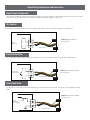
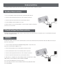
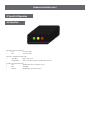
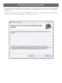
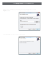
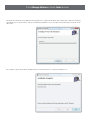
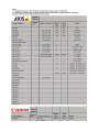
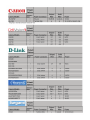
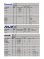
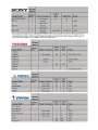
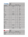
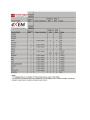
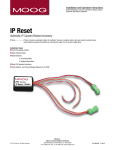
© 2011, Moog Videolarm, Inc. All Rights Reserved
IPRS01
IP Reset Device
www.videolarm.com
Installation and Operation Instructions for the following model:
IP Reset
IP Reset- provides a systematic solution for resetting IP cameras
or wireless systems, lock-ups caused by network issues, wiring
problems and power fluctuations by monitoring the output of an IP camera’s digital signal.
Installation Steps
1. Check the package contents
2. Select Operation Mode
3. Install Hardware
a. Timed Reset Mode
b. Intelligent Reset Mode
4. Read LED Operation instructions
5. Install Software- see IP Reset Manager Software (on CD-ROM)
Before attempting to connect or operate this product, please read these instructions completely.
81-IN5416
01-11-2012
IMPORTANT SAFEGUARDS
1
Read these instructions.
2
Keep these instructions.
3
Heed all warnings
4
Follow all instructions.
5
Do not use this apparatus near water.
6
Clean only with damp cloth.
7
CAUTION
RISK OF ELECTRIC SHOCK
DO NOT OPEN
Do not block any of the ventilation openings. Install in accordance with the
manufacturers instructions.
8
9
SAFETY PRECAUTIONS
Cable Runs- All cable runs must be within permissible distance.
CAUTION: TO REDUCE THE RISK OF
ELECTRIC SHOCK, DO NOT REMOVE
COVER ( OR BACK). NO USER- SERVICEABLE PARTS INSIDE. REFER SEVICING
TO QUALIFIED SERVICE PERSONNEL.
Mounting - This unit must be properly and securely mounted to a supporting
structure capable of sustaining the weight of the unit.
Accordingly:
a. The installation should be made by a qualified installer.
b. The installation should be in compliance with local codes.
c. Care should be exercised to select suitable hardware to install the unit, taking into
account both the composition of the mounting surface and the weight of the unit.
10 Do not install near any heat sources such as radiators, heat registers, stoves, or other
apparatus ( including amplifiers) that produce heat.
11 Do not defeat the safety purpose of the polarized or grounding-type plug. A
polarized plug has two blades with one wider than the other. A grounding type
plug has two blades and a third grounding prong. The wide blade or the third
prong are provided for your safety. When the provided plug does not fit into your
outlet, consult an electrician for replacement of the obsolete outlet.
12 Protect the power cord from being walked on or pinched particularly at plugs,
convenience receptacles, and the point where they exit from the apparatus.
13 Only use attachment/ accessories specified by the manufacturer.
14 Use only with a cart, stand, tripod, bracket, or table specified by the manufacturer,
or sold with the apparatus. When a cart is used, use caution when moving the cart/
apparatus combination to avoid injury from tip-over.
15 Unplug this apparatus during lighting storms or when unused for long periods of time.
16 Refer all servicing to qualified service personnel. Servicing is required when the
apparatus has been damaged in any way, such as power-supply cord or plug is
damaged, liquid has been spilled of objects have fallen into the apparatus, the
The lightning flash with an arrowhead symbol,
within an equilateral triangle, is intended to
alert the user to the presence of non-insulated
“dangerous voltage” within the product’s
enclosure that may be of sufficient magnitude
to constitute a risk to persons.
Este símbolo se piensa para alertar al usuario a la presencia
del “voltaje peligroso no-aisIado” dentro del recinto de los
productos que puede ser un riesgo de choque eléctrico.
Ce symbole est prévu pour alerter I’utilisateur à la presence
“de la tension dangereuse” non-isolée dans la clôture de
produits qui peut être un risque de choc électrique.
Dieses Symbol soll den Benutzer zum Vorhandensein der
nicht-lsolier “Gefährdungsspannung” innerhalb der
Produkteinschließung alarmieren die eine Gefahr des
elektrischen Schlages sein kann.
Este símbolo é pretendido alertar o usuário à presença “di
tensão perigosa non-isolada” dentro do cerco dos produtos
que pode ser um risco de choque elétrico.
Questo simbolo è inteso per avvertire I’utente alla presenza
“di tensione pericolosa” non-isolata all’interno della
recinzione dei prodotti che può essere un rischio di scossa
elettrica.
apparatus has been exposed to rain or moisture, does not operate normally, or
has been dropped.
Be sure to periodically examine the unit and the supporting structure to make sure that the integrity
of the installation is intact. Failure to comply with the foregoing could result in the unit separating
from the support structure and falling, with resultant damages or injury to anyone or anything struck
by the falling unit.
UNPACKING
Unpack carefully. Electronic components can be
damaged if improperly handled or dropped. If an item
appears to have been damaged in shipment, replace
it properly in its carton and notify the shipper.
Be sure to save:
1 The shipping carton and packaging material.
They are the safest material in which to make future
shipments of the equipment.
2 These Installation and Operating Instructions.
SERVICE
If technical support or service is needed, contact us at
the following number:
TECHNICAL SUPPORT
AVAILABLE 24 HOURS
1 - 800 - 554 -1124
The exclamation point within an equilateral
triangle is intended to alert the user to
presence of important operating and
maintenance (servicing) instructions in the
literature accompanying the appliance.
Este símbolo del punto del exclamation se piensa para
alertar al usuario a la presencia de instrucciones importantes
en la literatura que acompaña la aplicación.
Ce symbole de point d’exclamation est prévu pour alerter
l’utilisateur à la presence des instructions importantes dans
la littérature accompagnant l’appareil.
Dieses Ausruf Punktsymbol soll den Benutzer zum
Vorhandensein de wichtigen Anweisungen in der Literatur
alarmieren, die das Gerät begleitet.
Este símbolo do ponto do exclamation é pretendido alertar o
usuário à presença de instruções importantes na literatura
que acompanha o dispositivo.
Questo simbolo del punto del exclamaton è inteso per
avvertire l’utente alla presenza delle istruzioni importanti nella
letteratura che accompagna l'apparecchio.
Limited Warranty for Moog Videolarm Products
Moog Videolarm warrants these products to be free from defects in material or workmanship as follows:
PRODUCT CATEGORY
PARTS \ LABOR
All Enclosures and Electronics*
Five
Poles/PolEvators™/CamEvator
Three (3) Years
Warrior Series™/Q-View™/IR Illuminators
Five
(5) Years
SView Series™
Five
(5) Years **6 months if used in auto scan/tour operation
Controllers
Five
(5) Years
Power Supplies
Five
(5) Years
EcoKit
Three (3) Years
Accessory Brackets
Five
Liberty Dome
Three (3) Years
*DeputyDome™, NiteTrac™, Igloo Dome, PurgeDome™
Three (3) Years **6 months if used in auto scan/tour operation
(5) Years
(5) Years
During the labor warranty period, to repair the Product, Purchaser will either return the defective product, freight prepaid, or deliver it to Moog Videolarm
Inc. Decatur GA. The Product to be repaired is to be returned in either its original carton or a similar package affording an equal degree of protection with
a RMA # (Return Materials Authorization number) displayed on the outer box or packing slip. To obtain a RMA# you must contact our Technical Support
Team at 800.554.1124, extension 101. Moog Videolarm will return the repaired Product freight prepaid to Purchaser. Moog Videolarm is not obligated to
provide Purchaser with a substitute unit during the warranty period or at any time. After the applicable warranty period, Purchaser must pay all labor and/or
parts charges.
The limited warranty stated in these product instructions is subject to all of the following terms and conditions.
TERMS AND CONDITIONS
1. NOTIFICATION OF CLAIMS: WARRANTY SERVICE: If Purchaser believes that the Product is defective in material or workmanship, then written notice with an
explanation of the claim shall be given promptly by Purchaser to Moog Videolarm. All claims for warranty service must be made within the warranty period.
If after investigation Moog Videolarm determines the reported problem was not covered by the warranty, Purchaser shall pay Moog Videolarm for the cost of
investigating the problem at its then prevailing per incident billable rate. No repair or replacement of any Product or part thereof shall extend the warranty period
of the entire Product. The specific warranty on the repaired part only shall be in effect for a period of ninety (90) days following the repair or replacement of that
part or the remaining period of the Product parts warranty, whichever is greater.
2. EXCLUSIVE REMEDY: ACCEPTANCE: Purchaser’s exclusive remedy and Moog Videolarm’s sole obligation is to supply (or pay for) all labor necessary to repair any
Product found to be defective within the warranty period and to supply, at no extra charge, new or rebuilt replacements for defective parts.
3. EXCEPTIONS TO LIMITED WARRANTY: Moog Videolarm shall have no liability or obligation to Purchaser with respect to any Product requiring service during the
warranty period which is subjected to any of the following: abuse, improper use, negligence, accident, lightning damage or other acts of God (i.e., hurricanes,
earthquakes), modification, failure of the end-user to follow the directions outlined in the product instructions, failure of the end-user to follow the maintenance
procedures recommended by the International Security Industry Organization, written in product instructions, or recommended in the service manual for the
Product. Furthermore, Moog Videolarm shall have no liability where a schedule is specified for regular replacement or maintenance or cleaning of certain parts
(based on usage) and the end-user has failed to follow such schedule; attempted repair by non-qualified personnel; operation of the Product outside of the
published environmental and electrical parameters, or if such Product’s original identification (trademark, serial number) markings have been defaced, altered,
or removed. Moog Videolarm excludes from warranty coverage Products sold AS IS and/or WITH ALL FAULTS and excludes used Products which have not
been sold by Moog Videolarm to the Purchaser. All software and accompanying documentation furnished with, or as part of the Product is furnished “AS IS”
(i.e., without any warranty of any kind), except where expressly provided otherwise in any documentation or license agreement furnished with the Product. Any
cost associated with removal of defective product and installation of replacement product is not included in this warranty.
4. PROOF OF PURCHASE: The Purchaser’s dated bill of sale must be retained as evidence of the date of purchase and to establish warranty eligibility.
DISCLAIMER OF WARRANTY
EXCEPT FOR THE FOREGOING WARRANTIES, Moog Videolarm HEREBY DISCLAIMS AND EXCLUDES ALL OTHER WARRANTIES, EXPRESS OR IMPLIED,
INCLUDING, BUT NOT LIMITED TO ANY AND/OR ALL IMPLIED WARRANTIES OF MERCHANTABILITY, FITNESS FOR A PARTICULAR PURPOSE AND/OR
ANY WARRANTY WITH REGARD TO ANY CLAIM OF INFRINGEMENT THAT MAY BE PROVIDED IN SECTION 2-312(3) OF THE UNIFORM COMMERCIAL
CODE AND/OR IN ANY OTHER COMPARABLE STATE STATUTE. Moog Videolarm HEREBY DISCLAIMS ANY REPRESENTATIONS OR WARRANTY THAT
THE PRODUCT IS COMPATIBLE WITH ANY COMBINATION OF NON-Moog Videolarm PRODUCTS OR NON-Moog Videolarm RECOMMENDED PRODUCTS
PURCHASER MAY CHOOSE TO CONNECT TO THE PRODUCT.
LIMITATION OF LIABILITY
THE LIABILITY OF Moog Videolarm, IF ANY, AND PURCHASER’S SOLE AND EXCLUSIVE REMEDY FOR DAMAGES FOR ANY CLAIM OF ANY KIND
WHATSOEVER, REGARDLESS OF THE LEGAL THEORY AND WHETHER ARISING IN TORT OR CONTRACT, SHALL NOT BE GREATER THAN THE ACTUAL
PURCHASE PRICE OF THE PRODUCT WITH RESPECT TO WHICH SUCH CLAIM IS MADE. IN NO EVENT SHALL Moog Videolarm BE LIABLE TO PURCHASER
FOR ANY SPECIAL, INDIRECT, INCIDENTAL, OR CONSEQUENTIAL DAMAGES OF ANY KIND INCLUDING, BUT NOT LIMITED TO, COMPENSATION,
REIMBURSEMENT OR DAMAGES ON ACCOUNT OF THE LOSS OF PRESENT OR PROSPECTIVE PROFITS OR FOR ANY OTHER REASON WHATSOEVER.
! CAUTION:
IP Reset is not weatherproof. When connected to an outdoor camera Please make sure it is protected by a camera enclosure. Do not open IP Reset or all warranties will be
voided.
! WARNING:
To prevent fire or shock hazard, do not expose the unit to rain or moisture. To avoid electrical shock, do not open the unit. Refer servicing to qualified personnel only.
!
Product Specifications
Content of Box
IPRS01
IPRS01 Power Requirements
Input Voltage: 5 to 24 Volts AC/DC
English
Operating Current: 12ma
Device Power Requirements
Maximum Operating Current: 2 Amps
IPRS0
1 Serial
to suppo
24Vac
# 00165
Vin
Red
6
12Vdc
Orange
Vout withTested
FCC to comply
Red/Bla
Red(+)
standards
Orange/
Orange(
ck
Alarm
Red/Bla Black
-)
Brown
Orange/ ck(+)
Black
Black(-)
ply
F
th
wi
IPRS01
om
ar
nd
sta
CC
cati on i s stri ctly fo rbidd
du pl i
en .
An y
For
ds.
s up
po
rt c
all
180
Input Voltage: -25VDC to +25VDC
to
c
2
11
455
0-
4o
r se
nd
il
e-m a
I/O Detect Input
rm IPR S01 dev
ices o
nly.
Tes
te d
Application Software
for
IP RESET
deo la
For V i
rt at vid eolar m
.com
Maximum Switching Current: 5 Amps
Input Drive Current: 3ma @ 12V Typ.
Threshold: +1.9 VDC
I/O Cable Length: 6" or 15.2cm
Timer Mode Reset Cycle
12 Hours
IPRS
01
Se
rial #
24Va
Vin
0016
c
56
12Vd
OranRed
Vout withTesFCted to co
c
ge
C sta mp
OranRed/Blac
OranRed(+)
Alar ndardsly
ge/B k
ge(-)
Re
m
Br
Oran d/Black( lack
ge/B
Blacown
+)
lack(-)
k
Power Reset Period
5 Seconds
Environmental
Temperature: -40 to 158 Degrees F
-40 to 70 Degrees C
Humidity:
5 to 95 % non-condensing
Dimensions
Enclosure: 1.97" x 1.38" x 0.79"
50mm x 35mm x 20mm
NOTES:
² Ratings can be changed to meet customer’s requirements for
large orders. For the IPRS01 Reset Mode, your equipment must have
an I/O. If I/O cable is not connected (or incorrectly connected).
IPRS01 will operate in Timed Mode.
*** Pan Tilt boxed separately along with its instructions.
Operating Modes
The IP Reset operates in one of two modes, Intelligent Reset Mode and Timed Reset Mode. IP Reset automatically detects the operating mode by monitoring the I/O
Detect input. If IP Reset detects a change in the I/O Detect input, it will enter the Intelligent Reset mode. Otherwise, IP Reset will remain in Timed Reset mode. You
can choose to use Timed Mode by twisting the I/O Detect wires together and securing them with the wire nut.
Intelligent Reset Mode
The Intelligent Reset Mode monitors a relay output on the device being protected. The relay output on the IP device is commanded to toggle at a predetermined
interval using IP Reset Manager Software or other network software designed to support IP Reset. When IP Reset detects the loss of the relay toggle, after a
predetermined detection period, it power restarts the protected device. Generally, a power reset will restore the device to proper operation. After 2 failed attempts to
restore the device’s operation, IP Reset will re-start the protected device once every four hours (fault detection mode).
Timed Reset Mode
The Timed Reset Mode, simply cycles power on the protected device every 12 hours. When used in Timed Reset mode, IP Reset connects directly inline with the
device’s power, does not use the I/O Detect Cable and does not require any remote commanding software.
NOTE:
If Timed Reset Mode is used on a PTZ camera, the camera will typically reset to its home position upon reset. For this reason, we recommend using Intelligent Reset
Mode whenever possible for PTZ cameras.
Output Relay Configuration and Connections
Output Relay Configuration
The relay output configurations vary based on the manufactures design. Because of these variations, the IP Reset I/O Detect input needs to operate in one of three
ways. Refer to your camera user manual for more information regarding the output relay configuration of your camera.
Dry Contact
The first and most common method requires the IP Reset to supply current to the dry contacts of a relay. This configuration is shown in Figure 5.
Figure 5: Dry Contact Relay I/O
Detect Connection
BROW N
Came ra
Dry Contac t
I/O Detect Cable
BL ACK
Passive Solid-State
The second method is similar, requiring the IP Reset to supply current to an open collector output transistor. This configuration is shown in Figure 6.
BROW N
Figure 6: Passive Solid-State Relay I/O
Detect Connection
Came ra Open
Colle ctor Rel ay
Detect Cable
Appendix A – Output RelayI/OConfiguration
and
Connections (cont.)
BL ACK
Active Solid-State
The third and least common method is the emitter follower where the camera output supplies the current used for detection. In this configuration is shown in
Figure 7.
+ Volts
Figure 7: Active Solid-State Relay I/O
Detect Connection
BROW N
Came ra
Solid St ate
Sour cing Rel ay
I/O Detect Cable
BL ACK
Hardware Installation
The hardware installation depends upon the desired operating mode - Timed Reset Mode or Intelligent Reset Mode.
Timed Reset Mode Installation
1. Do not connect I/O Detect cable. Instead, twist wires together with provided wire nut.
2. Connect the power output pin from the IP Reset to the Power input on your device
3. Connect the power from the transformer to the power input in the IP Reset.
4. No IP Reset Manager Software installation is necessary.
Your IP Reset STD is now connected in Timed Mode. Your protected device should be operating and
power reset once every 12 hours.
IP RESET
IP Reset® Intelligent Reset Mode Installation
Operating the IP Reset® Intelligent Reset Mode requires an output connection to the protected device via the I/O Detect cable. The below illustrates the typical
connections for Intelligent Reset Mode
! WARNING !
If Intelligent Reset Mode connection is incorrect and IP Reset® does not detect I/O communication, IP Reset will remain in Timed Reset Mode and re-start your
device once every 12 hours.
1. Locate your camera in the IP Camera Compatability Chart (Appendix A). If your camera is not
listed, please contact Videolarm at (800)-554-1124.
2. Connect the Brown I/O Detect wire to the I/O terminal specified for your device.
3. Connect the Black I/O Detect wire to the I/O terminal specified for your device.
4. Connect the power output pin from the IP Reset to the Power input on your device.
5. Connect the power from the transformer to the power input in the IP Reset.
6. Add your device’s configuration to the IP Reset Manager Software or Network video recording
(NVR) software (See IP Reset Manager Software installation in CD-ROM).
Note 1: Connection polarity MUST be observed for all devices.
Note 2: If the input connections need to be modified, the Brown wire is plus VDC and the Black
wire is ground (0 VDC).
IP RESET
Hardware Installation (cont.)
IP Reset® LED Operation
LED Operation
Green LED – Device Power Indicator
•
ON : Power On to Device
•
OFF : Power Off to Device
Yellow LED – Communication/Signal Status
•
Timed Mode
: Flashes every second
•
Intelligent Mode
: Flashes every 90 Seconds (On = input High, Off = input Low)
Red LED – Operation Mode Indicator
•
ON : Intelligent Mode, device operating as expected
•
OFF : Timed Mode
•
Flashing
: Intelligent Mode, device fault detected
Software Installation (For a windows based PC)
If there is a preexisting version of the IP Reset Manager Software on your computer go to “Add/Remove Programs “from the MS Windows Control Panel and
remove it before beginning a new software installation.
To remove a preexisting IP Reset Manager Installation, go to the Windows “Control Panel” and click on the “Add or Remove Programs” software icon. After a few
seconds the following window will appear:
From the “Add or Remove Programs” menu below in Windows XP, select the program “IP Reset”. Click on the “Remove” button (See screen shot below)
In Windows XP/XP PRO
IP Reset
From the “Uninstall or change a program” menu in Windows Vista, double click on the “IP Reset by Videolarm” application.
In Windows Vista
In response to the confirmation box “Add or Remove Programs” message. Click “Yes”.
Software Installation (For a windows based PC continued)
In response to the confirmation box “Add or Remove Programs” message. Click “Yes”.
A window may show up as follows: Let this window run to completion.
Following the above window if you are removing the application from a computer with the Windows Vista operating system, a window (not shown) may
appear with the title “User Account Control”. It will say “An Unidentified Program Wants to Access Your Computer”, if this window appears you should
click “Allow”.
IP ResetSetup
While the software is being removed you will see the
following window
Wait till the above window goes away. At this point the IP Reset Manager Software will have been removed from your computer. You can now proceed
with the software installation.
IP Reset Manager Software Installation Guide
After you have fully removed any preexisting installations of IP Reset Manager (see section “Removing IP Reset Software” from your system), insert the CDROM that
came with your IP Reset device into the hard drive of the networked computer that will run the IP Reset Manager Software (computer must be on the same network
with the video cameras)
If the installation file doesn’t launch automatically, Double click on “setup.msi” file in the root directory of the supplied CDROM. A window pops up saying “Welcome
to the IP Reset Setup Wizard”, click the box that says “Next>”, if you accept the registration statement.
IP Reset Manager Software Installation Guide Continued
A Window pops up that says “Select Installation Folder”, if the radio button “just me” is selected, (shown below) than change it to the radio button
“Everyone”, as shown below
A window will appear that says, “Confirm Installation”, Click “Next >” to confirm the installation!
IP Reset Manager Software Installation Guide Continued
Following the above window if you are installing the IP Reset application from a computer with the Windows Vista operating system, a window (not shown) may
appear with the title “User Account Control”. It will say “An Unidentified Program Wants to Access Your Computer”, if this window appears you should click the
“Allow” option.
Once installation completes the final window “Installation Complete” is launched, Click “Close” to complete the installation process.
Older machines may require downloading Microsoft Dot Net
If you are on an older windows machine that does not have a current version of Microsoft’s Dot Net libraries, you may get a message from Windows requiring you to
download the latest version of Microsoft .Net. At this point you will have log on to Microsoft at:
http://msdn.microsoft.com/en-us/netframework/default.aspx
And download the latest version of Microsoft’s .Net libraries. After doing this double click on the downloaded files to install .Net. Once this has completed reboot
your computer.
Create an Exception for IP Reset Software from Windows Firewall
Select “Control Panel” from the start Menu
Select “Windows Firewall”
Click on “Allow a program through the Windows Firewall”
Click on “continue” if asked are you sure you want to do this or the “User Account Control” window appears
Under the “exceptions” tab on the “Windows Firewall Settings” menu, click the “Add Program …” Button
Click on the “Browse …” button
Browse to the installation directory for the IP Reset software. Unless you changed this directory for the installation you should browse to “C:\\Program Files\
Videolarm\IP Reset
Select “IPResetConfigurator.exe”
Click “OK”
Click “OK”
Exit the “Windows Firewall Settings”
Exit the “Windows Firewall”
Start the IP Reset Configuration Tool, “IPResetConfigurator.exe”
(For the following steps, you may get a message that says “.NET Framework” needs to be upgraded, In this case follow the instructions and upgrade “.NET” before
continuing)
Restart your computer and the centralized IP Reset control service launches automatically. You will see the IP Reset configurator application on the users startup
menu under the “All Programs” option. The name of the IP Reset configuration program is “IPResetConfiguratore.exe”.
The application is also installed on the user’s desktop and may be launched by clicking the IP Reset desktop Icon shown below:
IPResetConfig
urator.exe
Once launched the IP Reset Configuration application resides in the users “control tray” on the bottom right hand side of the screen. If the IP Reset application is
enabled the “Sunburst” Icon will blink. If the application is disabled the icon stays solid. The user can then program IP Reset devices by using the mouse button and
right clicking on this icon in the users tray.
IP Reset Icon in users Control Tray (red starburst)
You are now ready to run the IP Reset Configuration Software. For usage information refer to application users document “IP ResetSoftwareUsersGuide.pdf” which is
enclosed as a PDF with the CD-ROM. After successful installation the user’s guide and operations guide can be found on your computer in the following directory:
“C:\Program Files\Videolarm\IP Reset\IP Reset_Software_User_s Guide.pdf” is the application manual used to configure IP Reset devices from the computer. It describes installing the IP Reset devices to work with your cameras or other devices.
If you ever want to run the IP Reset software directly, browse to the IP Reset installation Directory, “C:/Program Files/Videolarm/IP Reset”, and double click on
the file “IPResetConfigurator.exe”. This will force the configuration application to launch manually.
Product Registration/Warranty
Thank you for choosing Moog Videolarm. We value your patronage and are solely committed to providing you with the highest
quality products available and superior customer service.
Should a problem arise, rest assure that Moog Videolarm stands behind its products by offering impressive warranty plans: 3 Years on all Housings, Poles,
Power Supplies, and Accessories and 5 Years on camera systems (SView, QView, Warriors), and InfraRed Illuminators.
Register Your Products Online
Take a few moments and validate your purchase via the Online Product Registration Form at
www.videolarm.com/productregistration.jsp
Register your recent Moog Videolarm purchases and benefit from the following:
• Simple and Trouble-Free RMA process
• Added into customer database to receive product updates / news
• Eliminate the need to archive original purchase documents:
Receipts, Purchase Orders, etc…