1
Operator's Manual
3/8 in. (10 mm) CORDLESS DRILL-DRIVER
Vadable Speed / Reversible
Model No.
315.101860 - 14.4 Volt
Save this manual for
future reference
,_
WARNING: To reducethe risk of injury,
the user must read and understandthe
operator's manual beforeusing this
product.
Customer Help Line: 1-800-932-3188
Sears, Roebuck and Co., 3333 Beverly Rd., Hoffman Estates, IL 60179 USA
Visit the Craftsman web page: www.sears.com/craftsman
983000-.409
6-04
• Warranty ...........................................................................................................................................................................
2
I
Introduction......................................................................................................................................................................
2
•
General Safety Rules ...................................................................................................................................................
I
Specific Safety Rules .......................................................................................................................................................
4
•
Safety Instructions for Charger ........................................................................................................................................
5
•
•
Symbols ...........................................................................................................................................................................
6
Features .......................................................................................................................................................................
7-8
•
Unpacking ........................................................................................................................................................................
•
Operaifon ....................................................................................................................................................................
•
Maintenance...................................................................................................................................................................
15
•
Notes ..............................................................................................................................................................................
16
3-4
8
9-14
• Explodod View and Repair Parts List .............................................................................................................................
17
•
18
Parts Ordering/ Service .................................................................................................................................................
FULL ONE YEAR WARRANTY ON COMPANION CORDLESS 3/8 In. DRILL-DRIVER
If this Sears Drill-Driverfails to give complete satisfactionwithin one year from the date of purchase, RETURN IT TO
THE NEAREST SEARS STORE OR SEARS SERVICE CENTER IN THE UNITED STATES_ and Sears will replace it,
free of charge.
If this Sears Cordless DiflI-Driver is used for commemialor rentalpurposes, this warranty applies for only 90 days h'om
the date of purchase.
This warranty gives you specificlegal rights,and you may also have other rightswhichvary from state to state.
Sears, Roebuck end Co., Dept. 817 WA, Hoffman Estates, IL 60179
This tool has many fsatures for makingthe use of this
productmore pleasant and enjoyable. Safety,
performance, and dependabilityhave been given top
priodty in the design of this productmaking it easy to
maintain and operate.
A
_l,
WARNING:
Do not attemptto use this product
until you mad thoroughly and understandcomplataiy
the operator's manual Pay dose attentionto the
safety rules, includingDangers, Warnings,and
Cautions. If you use this productproperlyand only
as intended,you willenjoy ysar_ of safe, reliable
service.
Look for this symbol to point out important
means attentionl!!
Your safety is involved,
safety precautions.
It
WARNING:
The operation of any tool can result in foreign objects being thrown into your eyes, which can
result in severe eye damage. Before beginningpower tool operation, always wear safety goggles
or safety glasses with side shields and a full face shield when needed. We recommend Wide
Vision Safety Mask for use over eyeglasses or standard safety glasses with side shields. Always
wear eye protection which is marked to comply with ANSI 7.87.1.
2
_i
WARNING!
READ AND UNDERSTAND ALL
INSTRUCTIONS, Failure to followall instruCtions
listedbelow, may resultin electricshock, fire and/or
seriouspersonaliniury.
•
Do not overreach. Keep proper footing end balance
at all times. Proper footingand balance enable better
controlof the tool in unexpeCtedsituations.
•
Use safety equlpmenL Always wear eye protection.
Oustmask, non-skidsafety shoes, hard hat, or hearing
protectionmust be used for appropriateconditions,
•
Do not wear loose clothing or jewelry. Contain long
hair. Loose d,othes,jewelry, or long hair can be drawn
into ai_vents.
•
Do not use on a ladder or unstable support. Stable
foo,dngon a sol)dsurtaca enables better controlof the
tool in unexpectedsituations.
SAVE THESE INSTRUCTIONS
WORKAREA
•
Keep your work area clean and well lit. Cluttered
benchesand dark areas Inviteaccidents.
•
Do not operate power tools in explcelve atmospheres, such as In the presence of flammable
liquids, gee(m, or dust. Power fools create sparks
which may Ignite the dust or fumes,
•
Keep bystanders, children, end visitors away while
operating a power tool. Dtstractfonscan cause you to
lose control.
ELECTRICAL
SAFETY
•
A battery operated tool with Integral batteries or a
separate battery pack must be recharged only with
the specified charger for the battery. A charger that
may be suitablefor one type of battery may create a
risk of fire when used with another battery.
•
Use battery operated tool only with specifically
designated battery pack. Use of any other batteries
may create a risk of fire.
Use battery only wlth charger listed.
[]ODEL
BAI"I'IERYPACK
CHARGER
315.101880
130122041
140209023
•
•
Do not abuse the cord. Never use the cord to carry
the charger. Keep cord sway from heat, o11,sharp
edges, or moving parts. Replace damaged cords
Immediately. Damaged cordsmay create a fire.
PERSONAL SAFETY
•
Stay alert, watch what you are doing and use
common sense w'nen operatfng a power tool Do
not use tool while tired or under the Influence of
drugs, alcohol, or merllcation. A momentof inattenlion while operating power tools may msuH in serious
personalinjury.
•
Dreea properly. Do not wear loose clothing or
Jewelry. Contain long heir. Keep your hair, clothing,
and gloves away from moving parts, Loose clothes,
jewelry, or long hair can be caught in moving pads.
• Avoid accidental atorUng. Be sure switch Is In the
lucked or off position before Incertlng battery pack.
Carryingtoolswith yourfinger on the switchor inserting
the battery pack into a tool with the switchon invites
accidents.
•
Remove e_uatlng keys or wrenches before turning
the tool on. A wrench or a key that is left attached to a
rotating part of the tool may resultin personalinjury,
TOOL USE AND CARE
•
Use clamps or other precUcst way to secure and
support the wod_
to a atabls platform. Holding
the work by hand or against yourbody Is unstable and
may lead to toss of control
• Do not force tool, Use the correct tool for your
application. The correcttool willdo the job better and
ea_er at the rate for wh'_h itis designed.
• Do not use tool If switch doe6 not turn It on or off. A
tool that cannotbe controlledwith the switch is danger~
ous and must be repaired.
• Disconnect battery pack from tool or place the
switch In the locked or off _
tx_fora _
any adjua_ment_ changing ac_mr, orlse, or storing
the tool, Such preventive safety measures reduce the
risk of startingthe toot accidan'm,y.
• Store Idle tools out of reach of children and other
untrafoed parsons. Tools are dangerousin the hands
of untrainedusers.
• When battery pack is not In use, keep It away from
other metal objects like: paper clips, coins, keys,
nails, screws, or other small metal objects that can
make a connection from one terminal to another.
Sho_ng the battery termi_ts together may cause
sparks,bums, era tim.
• Malntatn tools wfth care. Keep cutting tools sharp
end clean. Properlymaintainedtoolswith sharp cuffing
edges am less fikelyto bind and are easier to control.
[] Check for mlsstlgnment or binding of moving paris,
brenkage of parts, and any other condition tllat may
affect the tool's operation. If damaged, have the tool
serviced before using. Many accidentsare caused by
poorlymaintained tools.
[] Use only eooeasorles that are recommended by the
manufacturer for your model Accessoriesthat may
be suitable for one tool may oreale a riskof iniurywhen
used on another tcoi.
•
Keep the tool and Its handle dry, clean end free
from Oil and grease. Always use a clean clothwhen
cleaning, Never use brakefluids,gasoline, petroleumbased products,or any strongsolventsto clean your
tool. Followingthis role will reduce the risk of lossof
oont_ro{
and deteriorationof t'r_eenclosure plastic.
SERVICE
• When servlclng s tool, use only identical replacement parts. FollowInstructions In the Maintenance
section of this manuel. Use of unauthorizedparts or
failure to follow Malnlenance lnstruc_ons may create a
r_skof shock or injury.
• Tool service must be performed only by qualified
repair personnel. Service or maintenancepedormed
by unqualifiedpersonnel couldresultin e risk of injury.
•
Hold tool by insulated gripping surfaces when
performing an Operation where the cuffing tool may
contact h|dden wiring, Contactwith a "live"wire will
also make exposed metal paTtsof the tool"live"and
shockthe operator.
ADDITIONAL
Know your power tool. Rsmdoperator's manual
carefully. Learn its applicatfona end limitations, as
well as the specific potential hazards related to this
tool. Fotlowlngthis rule willreduce the riskof electric
shock,fire, or sedous injury.
•
Always wear safety glseemswith side shields.
Everyday glasses have only Impact resistantlenses.
They ere NOT safety glasses. Followingthis rulewill
reduce the dsk of eye injury.
•
[] DO not place battery tools or their batteries near fire
or heat. This wlll
reduce the dsk of explosionand
possibly
jury.
[] Batteriesvent hydrogengas and can explode in the
presence of a source of )gnltlon,such as a p)lotI}ght.
To reduce the risk of serious personalinjury, never use
any cesdless
productin the presence of open "flame. An
exploded battery can propeldebris and chemicals, if
exposed, flush with water immediately.
• Do not charge battery tool in • damp or wet Ioc_lion. Followingthis rule w_ reduce the risk of electric
shock.
RULES FOR SAFE OPERATION
•
IMPORTANT
electricshock, fire, or seriouspersonalinjury.
RULES
FOR BATTERY
•
For best results, your battery tool should be charged
In a tocatlon where the tempemtere Is more than 50°F
but less than 1QO°F.Do not store outside or in
vehicles.
•
Under extreme usage or temperature conditions,
battery Iselmge may occur. If liquid comes In
contact wlth your skin, wash Immediately with soap
and water, then neutralize with lemon Juice or
vinegar. If llquld gets Into your eyes, flush them
with clean water for st least 10 minutes, then seek
Immedlste medical attention. Followingthis rule will
reducethe risk of sedous personal Injury.
TOOLS
Battery tools do not have to be plugged into an
electrical outlet; therefore, they are always In
oper'etlng condition. Be aware of possible hazards
when not using your battery tool or when changing
accessories. Followingthis rule will
reducethe risk of
4
,A
chemicals that can damage, weaken, or dastmy
plastic.
WARNINGI
READ AND UNDERSTAND ALL
INSTRUCTIONS. Failureto followall Instructions
listed below, may re.suitin etect_ shock,fire and/or
serious personalinjury.
Before using battery charger,read all instructionsand
nautlonary markings In this manual, on battery charger,
battery,and productusing batteryto prevent misuse of
the products and possibleInjuryor damage.
• CAUTION: To reduce the dsk of electdc shock or
damage to the charger and battery, charge only nickelcadmium rechargeable battedas as specifically
designated on your charger, Other types of batteries
may burst, causing personal Injuryor damage.
• Never use a batterythat has been dropped or received
a sharp blow.A damaged battery Is subjectto
explosion. Propertydispose of a dropped or damaged
battery Immediately.
•
•
•
Do not expose charger to wet or damp conditions.
Water enteringcharger will Increasethe risk of electde
shock.
•
Do not use any attachment or accessory not
recommendedby the batery charger manufacturer.
Attachmentsand accessoriesthat may be suitable for
one tool may become hazardouswhen used on
another tool.
•
Do not abuse cord or charger. Never use the cordto
carry the charger. Do not pull the charger cord rather
than the plugwhen disconnectingfrom receptacle.
Damage to the onrd or charger could occurand create
an electdc shock hazard. Replace damaged cords
Immadlately.
•
Make sure cord is located so that It will not be stepped
on, tripped over, come In contact with sharpedges or
moving parts or otherwise subjectedto damage or
stress. This will reducethe dsk of accidentalfalls,
which couldcause injury,and damage to the cord,
whioh could resultIn electric shock.
• Keep cord and charger from heat to prevent damage to
housing or internal perts.
•
_,
Do not let gesollne, oils, petroleum-based products,
etc. come In contact with plastic parts.They contain
An extensioncord shouldnot be used unlessabsolutely
necassa_. Use of improperextension cordcould result
in e dsk offire and electricshock. If extensioncord
must be used, make sure:
a. "Thatpinson p|ug of extensioncord are the
same number,size and shape as those of
plug on charger.
b. That extensioncord is properly wired and in
good electricalcondition; and
c. That wire size is large enough for AC ampere
rating of charger as spec'd'ledbelow:
Cord Length(Feet)
Cord Size (AWG)
•
•
•
25'
16
50'
16
100'
16
Note: AWG = American Wire Gage
Do not operate charger with a damaged cordor plug,
which could cause shortingand electdc shock, ff
damaged, have the charger replaced by an authorized
serviceman.
Do not operate charger ff It has received a sharpblow,
been dropped, or otbe_vlse damaged In any way. Take
It to an authorized servicemanfor electrisal check to
determine ff the charger Is In good workingorder.
Do not disassemblecharger.Take It to an authorized
serviceman when service or repair Is required.
Incorrectreassemblymay result In a risk cAelectdc
shockor firs.
•
Unplug charger from outlet before attemptingany
maintenance or cleaningto reducethe risk of electdc
shock.
•
Disconnectcharger from the power supplywhen not In
use. This will reducethe risk of electric shock or
damage to the charger ff metal items shouldfall Into
the opening. It also will help prevent damage to the
charger dudnga power surge.
•
Save these Instructions.Referto them frequently and
use them to Instructothers who may use this tool. ff
you loan someonethis tool, loan them these
Instructionsalso to prevent misuse of the product and
possibleInjury.
WARNING:
Some dust created by powersanding, sawing, grinding,drilling,and other constructionactivities
contains chemicals knownto cause cancer,birth defects or other reproductiveharm. Some examples of these
chemicalsare:
• lead from lead-bssed paints,
• crysta,ine e_Scafrom bdcks and cement and other masonry products,and
• aTsenioand chromiumfrom chemica[ly-treated lumbar.
Yourriskfromthese exposuresvedes,dependingon how oftenyou dothistypeofwork.To reduceyourexposuretothese
chemicals: work in a weltventilated area, and work with approvedsafety equipment,suchas those dust masks that are
speciallydesignedto filterout microscopicparticles.
SAVE THESE INSTRUCTIONS
i Important: Some of the followingsymbolsmay be used on this tool. Please studythem and learn their meaning.Proper
Interpretationof these symbolswill allowyou to operate the tool better and safer.
SYMBOL
NAME
DESIGNATION/EXPLANATION
V
Volts
Voltage
A
Amperes
Current
Hz
Hertz
Frequency(cyctesper second)
W
Watt
Power
mln
Minutes
Time
AlternatingCurrent
Type of currant
=
Direct Current
Type or a characteristicof current
no
No Load Speed
Rotationalspeed, at no load
[]
Class II Construction
Double-insulatedoonsmJctlon
..Jmln
Per Minute
Revolutions,strokes,surface speed, orbitsetc., per minute
_lb
Safety Alert
Precautionsthat Involveyour safety
Read The Operator's Manual
To
thereduce
operator'smanual
the risk of Injury,the
before usingthis
user must
product.
read and understand
(_
Eye
(_)
Protection
Wet Dondltions Alert
Always
wear
gogglesor
safetythis
glasseswith
and
a full
facesafety
shieldwhen
operating
product. side shields
Do not
expose
to rain or use in
damp
locations.
The purposeof safety symbolsis to at'l_ct yourattentionto possibledangers.The safety symbols, andthe explanations
with them, deserve your careful attentionand understanding.The safety warningsdo not by themselves eliminate any
danger.The instructionsor warningsthey give are not substitutesfor proberacddent preventionmeasures.
SYMBOL
A
A
A
MEANING
DANGER: Indicatesan Imminentlyhazardous sltualJon,which, if not avoided,will resultIn death or
seriousinjury.
WARNING: Indicatesa potentiallyhazardous situation,which, if not avoided,cuuid resultin death or
seriousinjury.
CAUTION: Indicatesa potentiallyhazardous situation, wh|ch, if not avoided, may result in minor or
moderate Injury.
CAUTION: (W_'mut Safety Alert Symbol) Indicatesa situationthat may resultIn propertydamage.
PRODUCTSPECIFICATIONS
Chuck........................................... 3/8 in. (10 ram) Keyless
C[utoh............................................................... 4 Positions
Motor .............................................................. 14.4 Volt DC
Charger input ........................ _........ 120 V. 60 Hz, AC only
Switch ....................................................... Vadab[e Speed
Charge Rate ....................................................... 3-6 Hours
Gear Train ............................................................. 1 Speed
Torque.................................................................... 90 In.lb.
No Load Speed ................................................. 0-6501min.
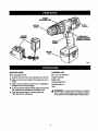
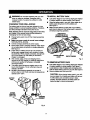
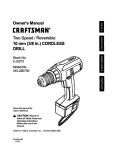
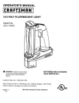
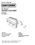
KNOW
YOUR
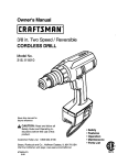
DRILL-DRIVER
See Figure 1,
Before attempting to use your ddll-ddver,familiarize
yourself with all operating features and safety
requirements.
WARNING: Carefully read throughttdsentire
operator'smanual before usingyour new dhlt-dr'rvar.
Pay close attention to all Salety Rules, Warnings and
Cautions. It you use your drill-driverpropertyand
only for what it Is Intended, you will enjoy years of
safe, reliable service.
,_
WARN|NG: Do not allowJamiliaritywith your rid}ldriver to make you careless. Remember that a
careless traction o1a second Is suff_em to Inflict
severe injury.
KEYLESS
CHUCK
Yourdrift-driverhas a keylesschuckthatallowsyou to hand
_ghten or releasedrillbit in the chuckjeers.
DIRECTION
OF ROTATION SELECTOR
FORWARD/REVERSE
Yourdrill-driverhas a forward/reverseselector located
above t_e sw}tchtrigger.The sw_chtdgger can be locked
in the OFF position.
SWITCH TRIGGER
To turn your drill.driverON, depressthe switchtrigger.
Release switchtrigger to turnyour drill-driverOFF.
VARIABLE
SPEED
This tool has a variable speed switch that delivers higher
speed with increased triggerpressure.Speed is controlled
by the amount of switch tdgger dapmse)on.
BIT STORAGE
When not In usa, bits pro'tidedwith your clflfl-drivarcan be
placed _ the storage area locatedon the top of the motor
housing.
TORQUE
ADJUSTMENT
RING
Your drill Is equipped with an adjustabletorque rk'vgfor
drivingdifferenttybes of screws intod_farent rnaterials.
The proper settingdepends on the type of material and
the size of the screw you are using.
TORQUE
ADJUSTMENT
RING
BIT
STORAGE
KEYLES8
CHUCK
CHARQER
ASSEMBLY
ROTATION
SELECTOR
(FORWARD/REVERSE)
TRIGOER
BAI-rERY
Fig. 1
INSTRUCTIONS
PACKING
LIST
When unpackingthe tool:
3/8 in, (10 mm) Drill-Driver
• Carefully remove the tool and accassodes from the box.
ChargerAssembly
•
Make sure that all items listedin the packing list are included.
Battery Pack
•
Inspect the tool carefully to make sure no breakage or
damage occurredduring shipping.
•
Do not discard the packing material untilyou have carefully inspected and satisfactorilyoperated the tool.
•
If any parts are damaged or missing,please call
1-800.932-3188 for assistance,
Double-ended Bit (2)
Operator'sManual
Case
,_
8
WARNING;
If any parts are missing do not operate
the tool untilthe missingparts are replaced.Failure to
do so couki resultin possiblesedouspersonal injury.
WARNING:Donot allow familiaritywith your drill-
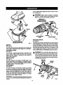
TO INSTALL BAI"I'ERY PACK
df',verto make you careless.Remember that a
careless fraction of a secondis sufficientto _nffict
severe Injury.
•
Lock switchIdggar on your drillby placingthe direction
of ro_a'_onselectorin center position.Sea F')gure3.
•
Place file battery pack in your drill.Align raised rib on
battery pack with groove in drill'sbattery pert.
See Figure 4.
MBJCe
sure the _tches on each side of your battery
pack snap in place and that battery pack is secured in
ddti before beginningoperation.
CHARGING YOUR DRILL-DRIVER
The battery pack for this tool has been shippedIn e low
charge condition to prevent passible problems. Therefore,
you should charge It at least 6 hourspdor to use.
•
Kote: Batterieswill not reach furlcharge the first time they
are charged. Atlowseveral cycles (drillingtoltowedby
recharging)for them to tullycharge.
•
[]
•
•
•
•
•
•
DIRECTION
OF
FLOTATION
SELECTOR
(i
Charge battery pack only with the charging assembly
provided.
Make sure power supply Is normal house voltage,
120 Volts, 60 Hz, AC only.
Connect charging assembly to power supply.
Place battery pack In chargingassembly.Align raised
rib on battery pack with groove in charging assembly.
See Figure 2.
Press downon battery pack to be sure contacts on
battery pack engage properlywith contacts in charging assembly, When pmpedy connected, red light will
turn on and remain on untilbattery is removedor
charger is unplugged.
After normal usage, 3 hoursof chargingtime is
required to be tully charged. A minimumcharge time
of 6 hours is required to recharge a completely
discharged battery.
The battery pack will become slightlywarm to the
touch while charging.This is normal and does not
indicate a problem.
DO NOT place charging assembly in an ares of
extreme heat or cold. It willwork best at temperatures
between 50°F-100°F.
CENTERPosmoN
(LOCiO
swrrcH'reuG
Fig. 3
TO REMOVE BAT'rERY PACK
•
II
•
Lock swit_ tr(ggaron your drill by placing the direction
of rotationselector in center pealtion. See Figure3.
Looatelatches
on sldeofbattery
peckanddeprsesboth
sidesto releasebatterypack [mmyourdrilLSee Figure6.
Remove battery pack from your ddti.
CAUTION: When placingbattery pack in your dritl,
be sure raised db on battery peck aligns with groove
in ddll"Bbattery pert and latches snap in place
properly.Improperassembly of battery pack can
cause damage to internalcomponents.
CHARGE
INDICATOR
LIGHT(teD)
,ASSEMBLY
F_g.2
9
To stop,release switchtriggerand allow the chuckto come
to a completestop.
_1= WARNING:
Battery tools ere always in operating
cond_on. Therefore, switch should always be locked
when not In use or when cerwIng at your side.
DIRECTION
OF
ROTAllONSELECTOR
(FORWARD
/ REVERSE)
BATrERT
PACK
REVERSE
BATrlERY
PORT
!
CENTER POSITION
(lOCK)
FORWARD
SWITCHTRIGGER
Fig. 5
KEYLESS CHUCK
DEPRESSLATCHESTO
RELEASEBATTERYPACK
See Figure 6.
A keylasschuckhas been providedwith yourddllto allow for
eas_JIr_mJlatton and ramoval ot b_ts.As the name '_las,
you can hand tighten or release drill bits in the chuck jaws.
Grasp and holdthe collar of thechuck withone hand. Rotate
the chuck body with your other hand. The arrows on the
chuck indicate which directionto rotate the chuck body in
order to GRIP (_ghten)or RELEASE (ur_ck) the ddll bit.
F'_.4
SWITCH
See Figure 5.
Your ddi]starts and stops by depressing and releasingthe
switch trigger. Release the switchbigger to turn ddll OFF.
VARIABLE SPEED
See Figure 5.
Your ddll has a variable speed feature in the switch. The
switch delivem higher speed and torque with increased
tdgger pressure. Speed is controlled by the amount of
switch trigger depression.
,_
SWITCH LOCK
See Figure 5.
WARNING:
Do not hold _ chuck body with one
hand and use the power ot the drill to tighten chuck
jaws on drillbits. Chuck bodycould slip in your hand
or your hand could slip and coma In contact with
rotatingddit bit.This could causean accidentrasu_ng
in sedouspersonal injury.
RELEASE
(UNLOCK)
The switch triggercan be locked In the OFF position.This
feature helps reduce the possibilityof accidental starting
when notIn use. To lockthe switchtrigger,place the direct'on
of rotationselector in the center position.
KEYI.ESS
CHUCK
REVERSIBLE
See Figure 5.
This tool is reversible.The directionof rotationis controlled
by a selector located above the switchtdgger. With the drill
held in normal operating position,the direction of rotation
selector should be positioned to the left of the switch for
drilling.The ddflingdirectionisreversedwhen the selector is
to the right of the switch. When the selector Is In center
position, the switchtrigger is locked.
BIT
GRip
(TIGHTEN)
CHUCK
COLLAR
CAUTION: To prevent gear damage, always allow chuck
to come to a completestop before changing the directionof
rotat|on.
Fig. 6
tO
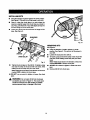
BIT STORAGE
SCREW'DRIVING
TORQUE ADJUSTMENT
See Figure 8.
When not in use, bits provided with your drillcan be
placed In the storage area locatedon the top of your drill
as shown in figure 8.
(Driving power of your drill-driver)
When using your drill-driverfor varlous driving applications, it becomes necessary to increase or decrease the
torque in order to help prevent the possibilityof damaging
screw heads, threads, workplace, etc. In general, torque
shouldcorrespondto the intensityof the screw diameter.
If the torque is too high or the screws too small,the
screws may be damaged or broken.
The torque "isadjusted by rotatingthe torque adjustment
ring. See Figure7. The torque is greater when the torque
adjustment ring is set on a higher setting. The torque is
less when the torque adjustmentdng Is set on a lower
setting.
BIT
STORAGE
The propersettingdepends on the type of materialand the
size of screw you are using.
TO ADJUST
TORQUE
Identify the four torque Indicator settingslocated on
the fi'ontof your drill.See Figure7.
Fig. B
Rotate adjustmentring to the desired set'ring.
• Position_:
For ddvingsmall screws.
• Pos_on 2:
• Pos_on3:
For ddvlngscrews Into soft material.
For drivingscrews into hard wood.
41,_1
For heavy ddUing.
TO DECREASE
TORQUE
TORQUE
/LJ),IUS'INENT
RING
Fig. 7
11
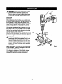
INSTALLING
BITS
•
Place thedirectionof rotationcelector in center position.
See Figure 5. This will turnoff the power to your drill.
•
Open or close the chuck jaws to a point where the
opening is slightlylarger than the bit size you intend to
use. Also, raise the frontof your drillslightlyto keep the
bit from fallingout of the chuck jaws.
•
lnsert your dntl bit into the chuck the full length of the
Jaws.See Figure 9.
RELEASE
(UNLOCK)
CHUCKBODY
Fig. 10
REMOVING
BITS
See Figure2.
•
Place the directionof rotation selector In center
posit_on.See Figure3. This will turn off the power to
your ddlL
•
Loocenthe chuck.jawsfrom dfitlbit.
• To loosen:grasp and holdthe cellar of the chuck wl_
one hand, whi_erotatingchuck bodywith your other
hand.
Note: Rotate chuck body in the directionof the arrow
marked RELEASE to _oosanchuck jaws.
•
DO NOT use s wrenchto tightenor loosenthe chuck
GRIP
(TIGHTEN)
CHUCKCOLLAR
Fig. 9
•
Tighten the chuck )aws on the drillbit.To tighten,grasp
and hold the collar of the chuck with one hand, while
rotatingthe chuck body with your other hand.
jews.
•
Note: Rotate the chuck bodyinthe directionof thearrow
marked GRIP to tighten the chuck laws.
• DO NOT use a wrench to tighten or loosen the chuck
laWS.
A
WARNING: Do not insertdrillbit into chuckjaws
and tighten as shown in Rgure 10. This couldcause
drtUt_t to be thrown _mm ddt_rasu_ng in passtbls
serious personalinjuryor damage to the chuck.
12
Remove ddllbit from chuck Jaws.
_1= WARNING: Always wear safety gogglesor safety
glasses with side shields when operatingtool,
Failure to do so could result in objectsbeing thrown
into your eyes, resultingin possibleserious injury,
DRILLING
See Figure 11.
When drillinghard, smooth surfaces, usa a canter punch
to mark the desired hole Iocallon.This wff!prevent the ddl[
bit from slippingoff canter as the hole is started. However, the lower speed feature allowsstarting holes without
canter punchingif desired. To accomplishthis, simply
operate your drillat lower speed untilthe hole Is started.
The matedsi to be ddlied shouldbe secured in a vise or
with clamp_ to keep It from turning as the drill bIt rotates.
Hold tool firmly and place the bit at the point to be drilled.
Depress the switch triggerto start tool.
Move the drillbit into the workpieca,applyingonly enough
pressureto keep the bit cutting. Do not force or apply side
pressure to elongate a hole.
_= WARNING:
Be prapaTedfor bindingor bit
breakthrough,When these situationsoccur, the drill
has a tendency to grab and kick oppositeto the
direction of rotationand couldcause toss of control
when breaking throughmaterial, if you are not
prepared, this loss of controlcan result in possible
sedous injury.
Fig. 11
When drillingmetals, use a light oil on the drillbit to keep
it from overheating.The oil will prolongthe life of the bit
and increasethe ddltingaction.
it the bit jams in workplace or if the drillstalls, release
switch triggerimmediately,Remove the bit from the
workplace and determine the reasonfor jamming.
13
CHUCK REMOVAL
TO RETIGHTEN A LOOSE CHUCK
See Figures 12 - 14.
The chuck may become iocse on spindle and develop a
wobble. Periodicallycheck the chuck screw for tightneSs.
To tighten,followthese steps:
•
Lockthe swiLchtriggerbyplscingthe directionof retation
selector in center position.See Figure 5.
•
Insert a 5/15 inch or larger hex kay Into the chuck of
your ddtt and [_ghtenthe chuck jews sscumly.
•
•
Tap the hax key sharply with a mallet in a clockwise
direction.See Figure 12. This will loosen the screw In
the chuck for easy removal.
•
•
•
Open chuck jaws end remove hex key, Remove the
chuck screw by turningit In a ctuck_se direcffon.
See Figure 13.
Note: The screw has left hand threads.
Inserthex key Inchuck end tightenchuck _ws securely.
"Tapsharp!,ywith e ma]_,a_
in e counterclock_se direction.
This will loosen chuck on the spindle, tt can now be
unscrewed by hand. See Figure 14.
Lockthe switchtriggerby piecing the direct_n ofrotation
selectorIn center position. See Figure 5.
Open the chuck jaws.
•
insert hex key into chuck and tighten chuck jaws
securety.Tap hex key sherptywith a mallet in a clockwise
direction,This will_ighten chuck on the spindle.
[]
Open the chuck Jawsand remove hax key.
•
"Tightenthe chuck screw.
Note: The chuck screw has left hand threads.
CHUCKJAWS
\
Fig.
Fig, 12
Fig. 13
t4
_lb
WARNING:
When servicing, use only identical
Craftsman replacement perts. Use of any other pert
may create a hazard or cause productdamage.
Do not abuse powertools. Abusive practicescan damage
tool as wall as workplace.
,_,
WARNING: Always remove the battery packfrom
the tool when assemblingparts, making adiustments,
cleaningor when not In use. Removingthe battery
peck wiltprevent accidentalsbartingthat could cause
sedouspersonalinjury.
Only the parts shownon parts list, page 17, are intended
to be repaired or replaced by the customer. All other parts
shouldbe replaced at a Sears Service Center.
_1= WARNING:
Do not attempt to mod_ this tool or
create acoessodesnot recommendedfor use with
this tool Any such alteration or modification is
mfsuce and could result In a hazardous cona'i6on
leading to possibte serious persona[ injury.
A
_,
WARNING: Always wear safety glasses with side
shieldswhen usingcompressed air to clean toots, it
the operation is dusty, also wear a dust mask.
Use clean clothsto removedirt, carbon dust, etc.
WARNING:
Do not at any time let brake fluids,
gasoline, petroleum-basedproducts,penetraUngoils,
etc. come in contact with ptssttcparts. They contain
chemicals that can damage, weaken or destroy
plastic.
BATTERIES
[]
The battery pack for the drill-driveris equipped with
nickel-cadmiumrechargeable batteries. Length of service
from each chargingwill depend on the type of work you
are doing.
The batteriesin this tool have been designed to provide
max=mumtroublefree life. t-lowever,tike artbattaries, they
wilt eventuallywear out. Do not disassemblebattery pack
and attemptto replace the batteries. Handfingof these
batteries, especially when wearing rings and jewelry,
could result In a seT_ousbum.
[]
Store and charge your batteries In a cool area.
Tempera_,uresbelow 50°F or above 10Q°Fw_l_shorten
battery life.
Never store battmles In a dischargedcondition.
Recharge them immediately after they are
discharged.
[]
All batterles gr_du_lty lose thelr chaTge..Thahlghar
the tt_npersture the o_ickerthey k_sett_ir charge. If
you store yoz_rtootfor Ioog periodsof time without
using R, recharge the batteries avery month or two.
Thl.spracticewill prok_ battery
IKe.
To obtain the longestposslb(e battery life, we suggest the
following:
BATrERY PACK REMOVAL AND
PREPARATION FOR RECYCLING
To preserverBtw_ resources,please
recy_e or dLsposeof batteries properly.
"Thisproductcontains n_cke_-cadmlum
batteries. Local, state or federal laws
may prohbit dispose| of nickel-cadmium
batteries in ordinary trash.
_,
WARNING: Uponremoval, cover the battery
pack's terminals with heavy duty adhesivetape. Do
not attempt to destroyor disassemblebattery peck
or remove any of its components.Nickel..cadm(um
batteries must be recycledor disposedof properly.
Also, never touchboth terminaJswith metal objects
and/or bodyparts as short c/muifmay result. Keep
away from ohltdren,Failure to comply with these
wam_ngscould result"mfire and/or serious'injury.
Consultyour Ioca/waste authorityfor information
regardingavailable recyclingand/or disposal options,
15
16
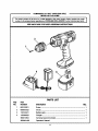
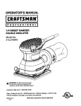
COMPANION
14.4 VOLT CORDLESS
DRILL
MODEL NO, 315.101860
I
The model
number
in all
number
correspondenceregardingyourCORDLESS
will be found on a plate attached to the
DRILL-DRIVER
motor housing.
or Always
when orderingrepair
mention the model
parts,
SEE BACK PAGE FOR PARTS ORDERING
]
INSTRUCTIONS
2
1
4
PARTS LIST
Key
No,
PaR
Number
Description
1
660120O01
Screw ..................................................................................................
1
2
690033022
Chuck ..................................................................................................
1
3
130122041
Battery pack ........................................................................................
1
4
140209O23
Charger ...............................................................................................
1
580013004
Carrying Case (not shown) .................................................................
1
983000-409
Operator's Manual
Qty,
17
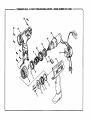
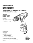
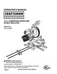
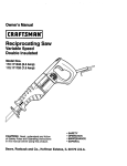
COMPANION 3/8 In. 14.4VOLT CORDLESS
DRILL-DRIVER
- MODEL NUMBER 315.101860
14
15
13
10
%,
:
9
11
P
12 _
8
7
6
5
3
2
1
4
14\
COMPANION 3/8 In. 14.4 VOLT CORDLESS
DRILL-DRIVER
- MODEL NUMBER 315.101860
|
J
CORDLESS
DRILL-DRIVER
or when
orderingrepair
The
model number
will be found
on a plate
attached toparts.
re motor housing.Always mention the model number In all correspondenceregarding your |
PARTS LIST
KEY
NO.
PART
NUMBER
DESCRIPTION
QTY.
1
6620501
2
6320801
* SCREW (M3 X 14 mm)................................................................................................................
MOUNTING PLATE .....................................................................................................................
3
6722101
4
5267710
BALL HOLDER ............................................................................................................................
1
5
6759001
WASHER ....................................................................................................................................
1
6
3656302
CLUTCH CAP ..............................................................................................................................
1
7
6320701
SPRING PLATE...........................................................................................................................
2
8
5267511
SLEEVE .......................................................................................................................................
1
9
BALL,,,,,,.*,,,*,,*,*.,*,*,*,*,**,,,,***,*.**,,,,,,
................
*.**.*,,*,*.*,,,,*,*,*,*,,,
.......................
*.*...*,,,*.,,*,,,,,,,,,,.,
4
1
6
680095001
SPRING .......................................................................................................................................
1
10
5369701
DETENT RING ............................................................................................................................
1
11
5260411
BIT CLIP ......................................................................................................................................
1
12
6711101
WASHER .....................................................................................................................................
1
13
6710501
CLUTCH WASHER ......................................................................................................................
1
14
200202154
HOUSING ASSEMBLY ................................................................................................................
1
15
67_'_001
BALL ..........................................................................................................................................
16
985348-001
MOTOR AND GEAR TRAIN ASSEMBLY ....................................................................................
1
17
270018018
SWITCH ASSEMBLY ...................................................................................................................
1
18
66206O6
* SCREW (M3.5 X 16 mm) .............................................................................................................
6
19
6620614
* SCREW (M3.5 X 14 mm) .............................................................................................................
OPERATORS MANUAL
2
983000-409
983000-409R
REPAIR SHEET
12-04-03
* STANDARD HARDWARE ITEM - MAY BE PURCHASED LOCALLY.
16
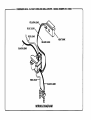
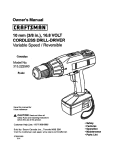
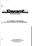
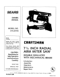
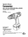
COMPANION 3/8 In. 14.4 VOLT CORDLESS
DRILL-DRIVER
- MODEL NUMBER 315.101860
BLUE LEAD
RED LEAD
HEAT SINK
BLACK LEAD
BLACK LEAD
RED
BLACK LEAD
WIRING DIAGRAM
Your Home
For repair-in your home-of all major brand appliances,
lawn and garden equipment, or heating and cooling systems,
no matter who made it, no matter who sold it]
For the replacement parts, accessories and
owner's manuals that you need to do-it-yourself.
For Sears professional installation of home appliances
and items like garage door openers and water heaters.
1-800-4-MY-HOME ® (l-eoo-4se-4s63)
Call anyUme, day or night (U.S.A. and Canada)
www.sears.com
www.sears.ca
Our Home
For repair of carry-in items like vacuums, lawn equipment,
and electronics, call or go on-line for the Ioca_on of your nearest
Sears Parts & Repair Center.
1-800-488-1222
Call anytime, day or night (U.S.A. only)
www,sears.€om
To purchase a protection agreement (U.S.A.)
or maintenance agreement (Canada) on a product serviced by Sears:
1-800-827-6655
(U.S,A.)
Para pedir servicio de reparacibn
a domicilio, y para ordenar plazas:
1-888-SU-HOGAR
(1-888-784.5427)
1-800-361-6665
(Canada)
Au Canada pour service en fran_ais:
1.800.LE.FOYERaC
s"
(1-800-533-6937)
www.sears.ca
8EAFR8
® RegiuteredTrademarkI _ Trademlrk / su _wl_
Mark o(Seara, Roebud,,andCo.
® MarneRegl_rada I xa Maroade Fibdca I m MerGede _dd o de 8earzz,p_
_
uc Mre'quade commerce I MDMarqued6pos6ede Seallk Roebud_andC_
_.
® _,
Roebuckmd Co.