1
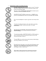
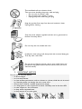
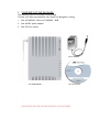
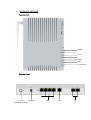
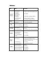
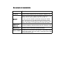
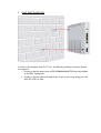
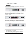
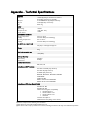
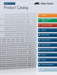
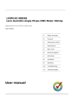
AT-iMG634 – R2 USER MANUAL AT-iMG634 – R2 User Manual This User Manual covers the following product: AT-iMG634 – R2 For a description of detailed functionality please refer to the Reference Manual. For installation and safety instructions please refer to this User Manual. 613-000480_B Copyright © 2008 Allied Telesis Holding K.K. All rights reserved. No part of this publication may be reproduced without prior written permission from Allied Telesis. Allied Telesis reserves the right to make changes in specifications and other information contained in this document without notice. In no event shall Allied Telesis be liable for any incidental, special, indirect, or consequential damages whatsoever, including but not limited to lost profits, arising out of or related to this manual or the information contained herein, even if Allied Telesis has been advised of, has known or should have known, the possibility of such damages. All trademarks are the property of their respective owners. ATTENTION All the information in this manual is property of Allied Telesis, please do not copy or reproduce all or part of this manual without permission. Please see below for the meaning of the icons used in this manual. CONTENTS 1 IMPORTANT SAFETY INSTRUCTIONS .................................................................................................................3 2 IMPORTANT NOTICE................................................................................................................................................4 3 CONTENTS OF THE PACKAGE..............................................................................................................................5 4 PRODUCT DETAILS....................................................................................................................................................6 TOP VIEW OF UNIT ...................................................................................................................................................................6 REAR VIEW OF UNIT .................................................................................................................................................................6 LED DESCRIPTION ....................................................................................................................................................................7 REAR PANEL PORTS AND BUTTON DESCRIPTION ..................................................................................................................8 5 UNIT INSTALLATION ................................................................................................................................................9 6 CONNECTING THE AT-IMG634 – R2................................................................................................................ 10 ADSL CABLE CONNECTION..................................................................................................................................................10 LAN CABLE CONNECTION ...................................................................................................................................................10 DISCONNECTING POWER SUPPLY .........................................................................................................................................10 APPENDIX - TECHNICAL SPECIFICATIONS............................................................................................................. 11 1 IMPORTANT SAFETY INSTRUCTIONS DO NOT OPEN the product, remove screws or cover. To prevent ELECTRIC SHOCK during normal use, the plastic chassis of the product must be kept closed. This unit contains HAZARDOUS VOLTAGES and should only be opened by a trained and qualified technician. DANGER: DO NOT WORK on equipment or CABLES during periods of LIGHTNING ACTIVITY to avoid ELECTRIC SHOCK. Do not use the telephone to report a gas leak in the vicinity of the leak. To avoid risk of electrical shock or fire, this device, connecting peripherals and cables, should not be used in an outside environment. Air vents must not be blocked. They must have free access to the environment air for cooling to prevent fire caused by excessive heating. To avoid the possibility of ELECTRIC SHOCK or FIRE caused by a short in internal circuits, do not place the device in any of the environments listed on point 2. To avoid FIRE risk, use this unit only with industry standard plugs and wiring suitable for your territory. Be careful not to drop water or any other harmful substance onto the product. This could lead to fire or electric shock. If the unit might get in contact with liquids, unplug the power and contact your support center or sales stores. This product contains parts that are sensitive to static shock. Please avoid touching interface connectors with bare hands. This could lead to fire or electric shock. Take care when handling the power cable and plug: • Do not strain the power cable • Do not place near a heater or stove • Unplug the power cable using the plug Keep the product free away from dust and maintain it clean. Unplug before cleaning. Only the power adapter supplied with this unit is guaranteed to function correctly with it. Do not drop the unit, handle with care. If really dirt, clean using a soft, damp cloth with a neutral detergent. Then dry with a soft cloth. Do not use oil, cleanser, thinner, petrol, wax, boiled water and powdered soap (please follow the instructions when you use a chemical duster). 2 IMPORTANT NOTICE Do not use or store the device: • In direct sunlight. • In a hot environment. • In a low-airflow environment, such as a drawer or a closet, while the unit is turned on. Restricting airflow can damage the unit or cause a fire. • Where there could be a sudden temperature change • In a damp place or near a liquid such as water. Humidity must be less than 80%. • In areas subject to a lot of vibration. • In dusty and/or carpeted areas. • In the presence of corrosive gases. 3 CONTENTS OF THE PACKAGE The following items are included in the package. Contact your sales representative if any items are damaged or missing. 1. One AT-iMG634 – R2A or AT-iMG634 – R2B 2. One AC/DC power adapter 3. One CD user manual Power Adapter AT-iMG634WA/B CD User Manual PLEASE NOTE THAT THE PACKAGE DOES NOT CONTAIN SCREWS. 4 PRODUCT DETAILS Top view of unit WLAN Tel 1 Tel 2 PPP ADSL LAN Power/System Rear view of unit Antenna POWER (AT-iMG634W Only) LAN ADSL Tel LED description Led Power/ System PPP LAN WLAN ADSL State Green light on The device is receiving power; voltage is within the acceptable range Red light on temporarily after power on Boot phase Red light on continuous An abnormal operating condition Red light flashing Software upgrade in progress Red light off The system is working normally Green light on PPP Link up Red light off No PPP link established Left Green light on Link up Left Green light off Link down Left Green light flashing Link activity Green light on Link up Green light flashing Transmission and reception of packets Green light on Link up Green light off or flashing slowly Link down Green light flashing quickly Link training Green light on LED turns on green when you lift the receiver of the telephone or fax connected to at least one VoIP port and remains on during the call Green light off Link down Green light flashing VoIP network is available Left Green light on Link up Left Green light off Link down Left Green light flashing Link activity Right Green light on 100Mbps link Right Green light off 10Mbps link Tel 1/ Tel 2 LANx Function Rear panel ports and button description Function Tel Port Connects analog telephone and fax through a telephone cord Used to reset the unit; it causes the default configuration to be loaded with the static IP address value of 192.168.1.1. Default Button To reset, press the ‘default’ reset button through the ‘default’ hole. Then power the unit while keeping the button pressed. When the system red light flashes to signal the starting of boot phase, wait another 15 seconds and then release the button. LAN Ports (MDI-X) Connects computer, HUB and switch with CAT.5 Ethernet cable ADSL Port Connects UTP from the ADSL network terminator Power Cable Provides the 12V DC power to this product. This product doesn’t have a power switch, you have to plug or unplug the power cable to turn the unit on or off 5 UNIT INSTALLATION In order to be compliant with ITU-T K.21, the following auxiliary protection devices are required: 1. Primary protection device such as EPCOS B88069X4960T502 must be installed on the DSL Tip/Ring pair. 2. Primary protection device installed on AC mains to limit surge energy into the Xavi unit’s PSU to 390V CONNECTING THE AT-IMG634 – R2 ADSL cable connection Plug the ADSL cable into the ADSL port until you hear a “click” and make sure it is correctly fixed by lightly pulling the ADSL cable. In the same way, Connect the plug on the other end of the ADSL cable to the terminator. LAN Cable connection Push in the plug of the UTP cable to the LAN port until you hear a “click” and make sure it is correctly fixed by lightly pulling the UTP cable. In the same way connect the plug on the other end of the UTP cable to the network interface card of the computer, or of the other LAN device. Disconnecting power supply This product doesn’t have a switch; it turns on automatically by connecting the power cable. To turn it off, just remove the power plug. ⇒ Note about functions and services (AT-iMG634 – R2) The VoIP Telephony provider may not offer all of the services that a standard telephony network usually provides. Similarly, some telephone or fax functions may not be available on the VoIP network. Please contact your VoIP Telephony provider for further details. Appendix - Technical Specifications Interface ADSL port LAN port TEL port WiFi 1 ADSL (6 pin RJ11 connector for Annex A, 8 pin RJ45 connector for Annex B) 4 10/100BASE-TX (8 pin RJ45 connector) 2 FXS (6pin RJ11 connector) 802.11b/g Power Input voltage DC input current Average power 12V DC 1.25A (DC 12V) 12.6W Environment condition Storage Temperature Humidity Operating Temperature Humidity -20°C to +40°C Less than 95% (non condensing) 0°C to +40° C Less than 80% (non condensing) Size (with no projection) 215 (W) x 151.35 (D) x45 (H) mm Weight 450g MAC address table size 1,000 (Max.) Memory Capacity RAM memory Flash memory 32 Mbyte 8 Mbyte Product Certification CE, FCC, UL Compliances (All Products) FCC Part15 Class B (only Annex A) FCC Part 68 (only Annex A) UL 60950 (only Annex A) EN55022, EN61000-3, EN61000-4, EN55024 CE EN60950 CE EN 300 386 ROHS = EU directive 2002/95/EC WEEE = EU directive 2002/96/EC Compliances (Wireless Model Only) ETSI EN 301 489 ETSI EN 300 328 WLAN electromagnetic compatibility EN 300 328 V1.7.1 EN 301 489-01 V1.6.1 EN 301 489-17 V1.2.1 EN 50371 FCC Part 15 Subpart C Notification for the placing on the market. This device complies with Part 15 of the FCC Rules. Operation is subject to the following two conditions: (1) this device may not cause harmful interference, and (2) this device must accept any interference received, including interference that may cause undesired operation.