1
351579-YTS-C-0111
TECHNICAL APPLICATION
AND
PROGRAMMING GUIDE
MILLENNIUM® SINGLE PACKAGE
ROOFTOP UNITS
25, 30 & 40 TON EQUIPPED WITH
SIMPLICITY® ELITE CONTROLS
MILLENNIUM® 25-40 TON SINGLE PACKAGE
COMMERCIAL ROOFTOP UNIT EQUIPPED
WITH SIMPLICITY® CONTROLS
This manual includes application, programming and service
procedures for the Millennium® 25-40 Ton Single Package
Commercial Rooftop Unit equipped with Simplicity® Controls.
These procedures are the same for all 25-40 Ton Millennium®
Rooftop units in this series except as noted.
This manual covers Simplicity® controls only, for unit installation
information please refer to the following.
RECOMMENDED TECHNICAL AND
INSTALLATION AIDS
Millennium® 25-40 Ton Single Package Installation and Operation
Manual - 524158
Millennium® 25-40 Ton Technical Guide - 246837
ISO 9001
Certified Quality
Management System
351579-YTS-C-0111
TABLE OF CONTENTS
MILLENNIUM® 25-40 TON SINGLE PACKAGE
COMMERCIAL ROOFTOP UNIT EQUIPPED WITH
SIMPLICITY® CONTROLS . . . . . . . . . . . . . . . . . . . . 1
RECOMMENDED TECHNICAL AND
INSTALLATION AIDS . . . . . . . . . . . . . . . . . . . . . . . . 1
THE MILLENNIUM® SIMPLICITY® CONTROL . . . . 3
INTRODUCTION AND OVERVIEW . . . . . . . . . . . . . . . . .
DIGITAL LINGO . . . . . . . . . . . . . . . . . . . . . . . . . . . . . . . .
ANALOG TO DIGITAL CONVERTER . . . . . . . . . . . . . . .
COMMUNICATIONS BUS . . . . . . . . . . . . . . . . . . . . . . . .
OPTIONAL Simplicity® LINC TRANSLATOR. . . . . . . . . .
COMPONENT DESCRIPTION. . . . . . . . . . . . . . . . . . . . .
3
4
4
5
5
5
CONTROLLING EXCESSIVE SAT (SUPPLY AIR
TEMPERATURE) . . . . . . . . . . . . . . . . . . . . . . . . . . . . . .35
SAT SETPOINTS USED DURING COOLING WITH
ECONOMIZER OPERATION . . . . . . . . . . . . . . . . . . . . .36
DEMAND VENTILATION . . . . . . . . . . . . . . . . . . . . . . . . .39
EXHAUST OPERATION . . . . . . . . . . . . . . . . . . . . . . . . .40
SCHEDULING OPERATION . . . . . . . . . . . . . . . . . . . . . .41
COMPRESSOR STATUS MONITORING . . . . . . . . . . . .41
TROUBLESHOOTING A MILLENNIUM®
SIMPLICITY® CONTROL . . . . . . . . . . . . . . . . . . . . 43
STATUS LED CHART . . . . . . . . . . . . . . . . . . . . . . . . . . .43
FAILURE MODES AND DEFAULT OPERATION . . . . . .43
SENSOR FAILURES AND DEFAULT OPERATION . . . .43
SYSTEM ERRORS . . . . . . . . . . . . . . . . . . . . . . . . . . . . .44
SIMPLICITY® PROGRAMMING OPTIONS . . . . . . . 11
INTERACTING THROUGH THE MILLENNIUM®
SIMPLICITY® . . . . . . . . . . . . . . . . . . . . . . . . . . . . . . . . 11
INITIAL STARTUP OPTIONS . . . . . . . . . . . . . . . . . . . . 11
METRIC OPERATION (ENGLISH) . . . . . . . . . . . . . . . . 11
SETTABLE SYSTEM PARAMETERS . . . . . . . . . . . 11
MILLENNIUM® SEQUENCE OF OPERATION . . . . 18
OVERVIEW . . . . . . . . . . . . . . . . . . . . . . . . . . . . . . . . . . 18
RUN SEQUENCE. . . . . . . . . . . . . . . . . . . . . . . . . . . . . . 18
UNIT CONTROLS SEQUENCE . . . . . . . . . . . . . . . . . . . 18
VARIABLE AIR VOLUME UNIT (VFD & IGV) . . . . . . . . 20
OCCUPIED / UNOCCUPIED / MORNING WARM-UP . 21
UNIT CONTROLS . . . . . . . . . . . . . . . . . . . . . . . . . . . . . 21
HEAD PRESSURE CONTROL . . . . . . . . . . . . . . . . . . . 26
SEQUENCE OF OPERATION - FOR HEAD PRESSURE
CONTROL. . . . . . . . . . . . . . . . . . . . . . . . . . . . . . . . . . . 26
INTELLI-START . . . . . . . . . . . . . . . . . . . . . . . . . . . . . . . 27
DEVICES AND RULES . . . . . . . . . . . . . . . . . . . . . . . . . 27
COMFORT VENTILATION MODE . . . . . . . . . . . . . . . . . 28
HYDRONIC HEAT . . . . . . . . . . . . . . . . . . . . . . . . . . . . . 29
COOLING LOCKOUT ON OAT . . . . . . . . . . . . . . . . . . . 29
WATER COIL FREEZE STAT (FSI). . . . . . . . . . . . . . . . 29
CV OPERATION . . . . . . . . . . . . . . . . . . . . . . . . . . . . . . 29
THERMOSTAT OPERATION FOR COOLING WITH Y1,
Y2, Y3 AND Y4 INPUTS . . . . . . . . . . . . . . . . . . . . . . . . 30
OPERATION FOR HEATING WITH W1, W2, AND W3
INPUTS . . . . . . . . . . . . . . . . . . . . . . . . . . . . . . . . . . . . . 30
SENSOR OPERATION . . . . . . . . . . . . . . . . . . . . . . . . . 30
TYPES OF SPACE SENSORS . . . . . . . . . . . . . . . . . . . 31
VAV OPERATION . . . . . . . . . . . . . . . . . . . . . . . . . . . . . 32
SUPPLY DUCT PRESSURE CONTROL ALGORITHM. 34
MORNING WARM UP / VAV OCCUPIED HEATING
CONTROL ALGORITHM . . . . . . . . . . . . . . . . . . . . . . . 34
2
LIST OF FIGURES
Fig. #
1
2
3
4
5
6
7
Pg. #
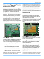
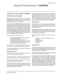
SIMPLICITY® CONTROLLER . . . . . . . . . . . . . . . . . . . 3
SIMPLICITY® CONTROLS PUSH BUTTONS . . . . . . 3
ANALOG TO DIGITAL CONVERTER . . . . . . . . . . . . . 4
VFD CONTROL WIRING . . . . . . . . . . . . . . . . . . . . . . . 8
SEQUENCE OF SETTING THE SET POINTS . . . . . 14
COMFORT VENTILATION ECONOMIZER
CONTROL . . . . . . . . . . . . . . . . . . . . . . . . . . . . . . . . . .28
SAT CONTROL BAND . . . . . . . . . . . . . . . . . . . . . . . 34
LIST OF TABLES
Tbl. #
1
2
3
4
5
6
7
8
9
10
11
12
13
14
Pg. #
ACRONYMS . . . . . . . . . . . . . . . . . . . . . . . . . . . . . . . . 6
INPUT SIGNAL TO Y1 ACTUATOR POSITION . . . . . 8
SIMPLICITY® CONTROL INPUTS . . . . . . . . . . . . . . . 9
SIMPLICITY® CONTROL OUTPUTS . . . . . . . . . . . . 10
SETTABLE SYSTEM PARAMETERS . . . . . . . . . . . . 16
COOLING STAGE . . . . . . . . . . . . . . . . . . . . . . . . . . . 19
IGNITION CONTROL BOARD FLASH CODES . . . . 23
MODULATING GAS HEAT . . . . . . . . . . . . . . . . . . . . 24
MODULATING GAS HEAT CONTROL BOARD FLASH
CODES . . . . . . . . . . . . . . . . . . . . . . . . . . . . . . . . . . . .25
COMPRESSOR MINIMUM OFF TIMES . . . . . . . . . . 30
WEEKLY SCHEDULE . . . . . . . . . . . . . . . . . . . . . . . . 34
HOLIDAY SCHEDULE. . . . . . . . . . . . . . . . . . . . . . . . 35
ALARM DEFAULT CODES . . . . . . . . . . . . . . . . . . . . 42
STATUS LED CHART . . . . . . . . . . . . . . . . . . . . . . . . 43
Johnson Controls Unitary Products
351579-YTS-C-0111
THE MILLENNIUM® SIMPLICITY® CONTROL
INTRODUCTION AND OVERVIEW
Welcome to the new Millennium® Simplicity® control, a digital
control system designed specifically for the Millennium® 25 to 40
Ton single package rooftop unit. The Simplicity® is composed of
72 monitored and controlled input and output points. The control
logic of the Simplicity® extends on the rules built in to the
Synthesys control, and provides character displays in addition to
LED flashes to display information to the technician.
The Simplicity® digital control performs all of the control and
monitoring functions that were originally done by separate
discrete relays, controls, and interlocking hardware. This
reduces manufacturing, service, and maintenance costs. The
Simplicity® digital controller includes sophisticated control of
the individual components of the HVAC cooling/heating unit,
and has built-in rules that protect those components and
optimize the control to its environment. The cooling and heating
modes are protected against frequent cycling, slugging,
multiple restarts, etc.
The Millennium® Simplicity® control is resistor-configured for
Constant Volume (CV) units or Variable Air Volume (VAV) units.
The option settings for a specific option configuration will be
made as part of unit test at the factory; however, if there is
doubt about how a unit is responding in the field, check the
option setting for the unexplained action.
If connected to a network, the control requests an address by a
press of the Address/Down button.
DIAGNOSTICS VIA LED
There is an LED on the board that shows the status of the
control and alarms (see Status LED Table). There are two
character displays, one 2-digit and one 4-digit, to indicate
details of run conditions and alarms (see Alarms Table in the
Trouble Shooting section of this manual).
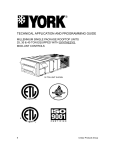
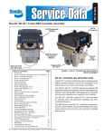
When the Alarm / Change Data button (See Figure 2 Simplicity®
Controller Push Buttons) is pushed and released one time within
five seconds, it will re-enunciate the last five alarms on the
Display.
Program
Alarms / Change Data
Test / Reset / Up
Address / Down
Figure 2: Simplicity® Controls Push Buttons
Figure 1: Simplicity® Controller
One result is that the system may not immediately respond as
you expect. For example, internal digital timers may delay the
start of a compressor even though the thermostat calls for
cooling. The control may be in the middle of a timing sequence;
without the observer knowing what has already happened and
the status of current inputs, the system may take action not
expected by the tech.
®
In the Simplicity control, there are:
• a list of user-selected option settings and setpoints
recorded within the control;
• inputs monitored by the Simplicity®;
• specific fixed rules and timings built in to the control
• outputs to compressors, heat, economizers, and other
options.
Simplicity®
The
has a real-time clock function, with minimum of
ten hours “Time-of-day retention” with unit power off.
Johnson Controls Unitary Products
When this button is pushed and released two times within five
seconds, it will clear all stored alarms.
The error details for most conditions are stored in summary in
the Simplicity® Control and can be accessed by the digital
display, personal computer interface, or Palm Pilot (Some
interfaces still in development).
Diagnosing requires patience because of internal timings.
Normal observable conditions are the same - contactor 1M
pulled in, compressor 1 running - but the control does not
identify what it has just done or is about to do. The Simplicity®
control will take action according to its internal rules even
though action requests come from smart thermostats. A call for
cooling, for example, will be compared with supply air
temperature before energizing a cooling stage.
ERROR HISTORY
The Simplicity® control stores up to 5 of the most recent alarms
in a First In, First Out (FIFO) manner. As the control collects
3
351579-YTS-C-0111
alarms, it will overwrite the oldest alarm after the history buffer
becomes full.
depending on how long the sensed value remains away from its
desired setpoint.
Some system errors will initiate a controlling response as well
as being stored in the error memory buffer. See the
“Troubleshooting” chapter in this manual for a detailed
description of how controller errors are handled.
Fortunately, you do not have to determine all of these
parameters since they are pre-programmed at the factory. You
need only to set a desired setpoint and ensure that the inputs
and outputs are properly wired and working. This is referred to
as commissioning a system.
Data items stored for maintenance / run history, in addition to
Alarms:
• Accumulated run times for each compressor and heat stage
• Unit model number
• Unit serial number
• Unit Name
DIGITAL LINGO
This training manual is intended to help you with the
commissioning process by illustrating the use of tools like the
control’s digital input and software engineered specifically for
starting up and servicing a Millennium® rooftop unit.
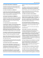
ANALOG TO DIGITAL CONVERTER
Computers can only understand a simple binary language.
Remember, “binary” means two states - ON or OFF. Analog
(continuous) values of voltages, currents, and resistances are
supplied by sensors and transducers to the control. These
values must be converted in to a binary code so that the
computer can understand them. This conversion process is
performed through a combination of hardware and software.
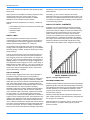
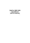
For example, the 0-5VDC analog value from a static pressure
transducer is divided into thousands of steps with a binary
coded number, often called “counts”, assigned to each step.
You should become familiar with some common terminology
and lingo used in the digital controls industry. (If you are familiar
with the Synthesys controller, the logic of the Simplicity® will be
familiar territory.)
If this is your first exposure to the world of digital controls you
may experience a lot of new terms, acronyms and technical
lingo commonly used in the controls industry. For example, the
Simplicity® input and output hardware points are described as
analog, relating to a continuous scale of value readings such
as a temperature sensor ranging from -400F to 1600F range, or
binary, meaning 2-states, either on or off, open or closed, true
or false, one or zero. The term “digital” also means two states
and its use is often interchanged with “binary”. These points
may be either factory- or field-set.
THE PI ALGORITHM
0
Another common “digital controls” term is the PI algorithm or
Proportional-Integral control loop. The PI algorithm is a
continuously updated math calculation that the controller uses
to modulate an analog output point. For example, a variable
speed drive uses a PI loop to maintain a desired setpoint (in this
case, a duct static pressure value). The algorithm takes into
account several parameters to calculate the output. The PI loop
needs parameters such as the proportional operating
bandwidth, integral time constant, deadband, desired setpoint
value, sensed input value(s), start up ramp time, initial start
value, maximum output control value, a status point to initiate
the control action (i.e. a fan ON status), Direct or Reverse
Controlling Action, and several other parameters to calculate a
simple 0 to 100% analog output control. The PI algorithm is also
called a PI loop because it “loops” the output back to the input
(feedback) and determines a new output value based on the
“error” or difference between the setpoint value and the sensed
input value, and how that difference relates proportionally to the
0 to 100% output value. Time is the ”integral” constant that is
factored in to increase or decrease the controlling output action
4
1
2
3
4
5
6
7------------- n
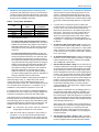
BINARY NUMBER EQUIVALENT
Figure 3: Analog to Digital Converter
SOFTWARE TERMINOLOGY
A digital controller handles its control functions through software
programming rather than with interlocking hardware and wiring.
The software then becomes key to how controlled functions are
handled. Software is a set of statements (referred to as the
“program”) that define the function of the controller’s internal
microprocessor computer.
Software procedurally tells the computer the sequence and
order of tasks that need to be performed using a language that
the computer can understand.
Software is stored in a computer’s memory. There are several
types of memory in a computer. Each type has a specific
function to perform.
Johnson Controls Unitary Products
351579-YTS-C-0111
EPROM - This is “nonvolatile” memory, meaning it will not be
erased on a power loss. This memory is usually programmed
prior to assembly of the controller. Since this memory is not
changed during normal operation of the Simplicity® control, only
basic operation instructions are stored in this type of memory.
OPTIONAL Simplicity® LINC TRANSLATOR
OVERVIEW
EEPROM (Double “E” Prom) - Is also non-volatile, but this
type of memory requires a special process to be written to. This
memory can be written to and changed by the microprocessor.
This is the type of memory that the control program is stored in
the Simplicity® control.
The Simplicity® LINC translator operates as a Modbus® Client
providing an interface between a BACnet® control system and
devices that communicate using the Modbus® RTU protocol. The
Simplicity® LINC is preconfigured to provide an interface to
YORK UPG products equipped with an Intelli-Comfort or
Simplicity Elite™ controller and allows monitoring and control by
a third-party BACnet® Building Automation System (BAS).
ROM - Read Only Memory is non-volatile but can not be written
to. This memory is programmed only once before the controller
is assembled. ROM contains instructions specifically for the
internal microprocessor computer in the controller.
The Simplicity® LINC communicates using the Modbus® RTU
protocol on one port and BACnet® MS/TP. By providing different
communication protocols on the two ports, data can be
retrieved from and provided to two different systems.
FIRMWARE - “Firmware” is software, program instructions or
applications, but stored in EPROM or ROM memory.
The Simplicity® LINC mounts inside the control panel of the
UPG unit and utilizes 24 VAC power from the unit's control
transformer. One port is connected to the UPG controller. The
other port must be connected to the BACnet® network.
RAM - Random Access Memory is a volatile memory. It will be
erased when a power fail occurs. This memory is used as a
kind of “scratch pad” for the controller. Temporary instructions
and information such as an output controlling action like driving
the economizer dampers open is stored here. When a power
loss occurs or if the controller is sent a manual reset using a
control push button, this memory is cleared and initialized.
Other filtered inputs include temperature and humidity sensors.
You should be aware of this filtering effect because it will
appear the controller is not acting as fast as you may think it
should. In reality, it is acting and controlling on these timeaveraged and weighted values.
FAULT TOLERANCE - Fault Tolerance of the Simplicity® control
involves two issues: Hardware fault tolerance deals specifically
with the electrical characteristics of the controller - how much
over voltage or power surge the controller can withstand before
damage occurs, and whether internal comparisons are verifying
that the control is calculating and communicating properly.
Software fault tolerance in this technology consists of comparing
results to previous values and to reasonable values.
COMMUNICATIONS BUS
Networked communications may also be new to you. It relates
to connecting several Millennium® rooftop units to a network
that can be monitored and controlled remotely from network
computer workstations. You will find this typically on large
installations where central control, monitoring, and energy
management issues become a critical factor in operating a
large complex such as a manufacturing facility.
The Simplicity® Control has the ability to be networked into a
larger system using the MODBUS communication protocol. A
communication protocol is simply a set of rules that determine
how two systems communicate with each other over some
medium such as a pair of wires, phone line, radio waves, etc.
The transmission medium may also be called a gateway,
pathway, or bus. An “open” protocol such as MODBUS is a
publicly published set of rules that any equipment manufacturer
can use to network into another manufacturers equipment.
Johnson Controls Unitary Products
The Simplicity® LINC translator is preconfigured to obtain
operational data points from the controller and expose them on
a BACnet® network.
"The Simplicity® LINC device is primary a control offered and
configured by York's ESG (Engineering Systems Group). The
device is designed to tie into and function with a BACnet®
MS/TP network. The device can be used with other BACnet®
MS/TP systems, but a qualified controls contractor must be
involved. UPG cannot support the Simplicity® LINC device
beyond its hardware functionality and cannot guarantee
functionality with other third party BAS devices."
Please refer to the Simplicity® LINC Installation Manual P/N
514066 and Application Guide Part Number 514067.
COMPONENT DESCRIPTION
This section describes the main components of Millennium®
Simplicity® control. These components consist primarily of
controllers, hardware to handle signal input and control output
and the Tstat interface terminals.
THE Simplicity® CONTROLLER
Simplicity® is a proprietary, microprocessor-based controller for
use in HVAC applications. The controller provides monitoring
and control for either VAV or CAV for a total of 22 outputs.
WIRING AND TERMINATION, COMMUNICATIONS
Most connections to the Simplicity® Control are by wiring
harnesses. There are also screw terminal connections for
thermostat inputs and for communications via an RS-485 port.
COMMUNICATION ADDRESS
The communication address button (lower right of the display)
is used to identify a Millennium® rooftop unit to a network, and
“capture” the next available network address for that unit.
Millenniums can be networked together for centralized
5
351579-YTS-C-0111
monitoring and control. Much like we need a unique street
address in our homes so we can receive our postal mail or
emergency services, these units also need a unique address so
the central Facilities Management System (FMS) can “talk” to
each unit individually. The Simplicity® board has the model and
serial number of the specific unit and has a memory space for a
customer name to be applied. So the entire identification for a
specific unit available to the network could be, for example,
Y2AC04M3KDGABA, NCNM123456, SOUTH OFFICE.
The one-time commands to Override ASCD timers and/or to
start Run Test can be issued by the Test/Reset/Up pushbutton.
When this button is pushed and released within five seconds,
the control will zero all ASCD’s for one cycle.
ACRONYMS
A number of acronyms are used throughout this training
manual. These are specific to the Simplicity® control. They are
also used in the Technical Guide and Installation and Operation
manuals. Acronyms are used to refer to input and output
hardware points and software parameters such as timing delays
and setpoints.
Table 1: Acronyms (Continued)
Pushbuttons
Description
Test/Reset / 'Up
'Test / control reset / Data value increment
Address / 'Down
'Change data / Data value decrement
Alarms / Advance data
Show alarms / go to next data point
Program
Go to program mode
Real Time Clock
Incorporated on the board
Outputs
Description
Status LED
Flash to indicate alarm, otherwise
'heartbeat'
Digital displays
One 2-character and one 4-character
C1-C4
Cooling Outputs 1 through 4
CF1, 2
Cond Fan Bank 1, 2
ECO
Economizer damper output
EXH
Exhaust Fan relay output
EXD
Exhaust Air Damper / Exhaust VFD Signal
Output
Fan
Supply Fan relay output [contactor or
permission relay]
H1, 2, 3
Heating Stages 1, 2, and 3 output
Table 1: Acronyms
Inputs
6
Description
HGR
Hot gas reheat [future]
HWV
Hot Water Valve output
VFD
Supply Fan IGV or VFD Signal Output
Alarm signal
APS
Air Proving Switch
X
IAQ
Air Quality (CO2 Sensor)
Miscellaneous
Description
BAS Economizer
Passes BAS economizer command through to
Economizer output
AI
Analog Input
AO
Analog Output
BPS
Building Pressure Sensor
BI
Binary Input same as
C1O-C4O
Compressor Status
BO
Binary Output
DF
Dirty Filter Status
CAV
Constant Air Volume
DPS
Duct Pressure Sensor
VAV
Variable Air Volume
FSI
Hot Water Coil Freeze Input
VFD
Variable Frequency Drive
G
Thermostat input for Fan
IGV
Inlet Guide Vane
GV1-3
Monitors gas valve actuation call
IAQ
Indoor Air Quality
HPS1-4
High pressure switch monitored for
compressor discharge
LPS1-4
Low pressure switch monitored for compressor
suction
Lim 1-3
Over-temperature limit switch from heat stages
OAT
Outside Air Temperature
OCC
Building Occupied Status
Purge
Building Purge input
RAT
Return Air Temperature
SAT
Supply Air Temperature
SD
System Shutdown Connector
OAH
Outside Air Enthalpy
RAH
Return Air Enthalpy
SSA
Setpoint Adjust
ST
Space Temperature
W1, 2, 3
Heating Stages from Tstat
Y1,2 3, 4
Cooling Stages from Tstat
PI
Proportional-Integral Control
ASCD
Anti Short Cycle Timer (Compressor)
The acronyms used throughout this training manual are listed in
the Acronym Table 1. They are described in much more detail
below.
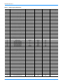
INPUTS
There are two types of hardwired input points on the Simplicity®
control: Analog and Binary. These may be sensors, feedback,
or adjustable setpoints. Typical analog inputs [AI] include Space
Temperature (ST), Supply and Return Air Temperatures (SAT,
RAT), and Building Pressure Sensor (BPS). The binary inputs
(BI) on the Millennium® Simplicity® use a dry contact input to
determine the status of a monitored point. Typical BI points are
Fan Status (APS), Filter Status (DFS), and Compressor Status
(HPS1-4, LPS1-4, C1O-4O).
Johnson Controls Unitary Products
351579-YTS-C-0111
ANALOG INPUTS (AI)
Analog inputs require parameters that define the input’s
characteristics. Attributes of an AI include the linear range,
alarm limits, alarm differential, change of state (COS) enable,
and filter weight. The input values may be overridden by a
external system command or by using the input buttons on
the Simplicity® board. This is useful to override current
conditions to test certain control functions or modes.
BAS - Economizer override; if this option is enabled, an
external BAS system will control the economizer 2-10 VDC
signal through this pair of terminals.
ST - Space Temperature sensor is a field installed sensor
(PN: 025-38928-000 - w/ Override Button). The sequence of
control for space temperature is different depending on
whether the system is a VAV or CAV. See chapter on
Sequence of Operation for a detailed description of the ST
control modes.
SSA - Space Temperature Adjust is field installed. It is a slide
adjustment located on a space sensor (PN: 025-38927-000)
with a slide bar potentiometer. It is used to offset the space
temperature setpoint. This slide-bar is a 10K ohm
potentiometer. The programmable range for the Setpoint
adjust is +/- 5 °F. For example, if the Space Temperature
setpoint is set to 74 °F, the SSA is programmed to +/- 3 °F and
the SSA is adjusted fully to the + position, the new controlling
space setpoint will be 78 °F.
OAT - The outside air temperature sensor (PN: 031-01916000A) is a factory-installed 10 K NTC sensor. Its linear
ranging is from -50 °F to 250 °F.
OAH - Outside Air Humidity (PN: 031-09127-000-A) is a
factory-installed sensor manufactured by MAMAO. The OAH
sensor, installed only with enthalpy economizer, provides a 010 VDC signal to the controller over a range of 0 to 100%
relative humidity. This input is used for the economizer
calculation to determine whether free cooling is available and
to switch between minimum outside air and using outside air
as the first stage of cooling.
SAT - Supply Air Temperature sensor (PN: 031-01915-000A)
is a factory-installed -50 °F to 250 °F, 10 K NTC sensor.
RAT - Return Air Temperature sensor (PN: 031-01917-000A)
is a factory-installed -50 °F to 250 °F, 10 K NTC sensor.
RAH - Return Air Humidity (PN: 031-09127-000-A) is a
factory-installed sensor manufactured by MAMAO, installed
only with dual enthalpy economizer. The control will calculate
the return air enthalpy using the relative humidity and return
temperature inputs.
LOW VOLTAGE DETECTION - This input monitors the 24
VAC for low voltage conditions. The input has two thresholds,
one at 16 VAC and one at 19.2 VAC. If the control needs to
turn on a contactor, it will look to see if the voltage is
above19.2 VAC before it will turn it on. If the voltage is not
above 19.2 VAC, it will hold off the contactor and flash the
appropriate flash code. This flash code is not an alarm. If the
control already has contactors pulled in, it will monitor the
Johnson Controls Unitary Products
voltage and drop the contactors and shut down if the voltage
drops below 16 VAC and flash the appropriate flash code.
REMOTE - the control will use 0-10 VDC from third-party
BAS to control SAT setpoints. Thermostat inputs override if in
conflict with Remote Control voltage input.
SPC TEMP - offset value from the space sensor offset
potentiometer.
CV/VAV - resistive value across terminals, to determine
which supply fan rules the control will follow.
Demand Ventilation / IAQ - Indoor Air Quality. The IAQ
expects a 0-10 VDC signal to the control from a field supplied
and installed Carbon Dioxide (CO2) sensor. Indoor air quality
is monitored for adequate ventilation. In Demand Ventilation
Mode, as the CO2 levels in the building rise above the
programmed setpoint, more fresh air must be brought in. The
economizer is therefore adjusted to a more open position as
necessary. The linear ranging for IAQ sensor input is from 0
to 10,000 ppm. The Demand Ventilation setpoint is adjustable
from 0 to 2000 ppm and is set at the factory at 1000 ppm.
DPS - Duct Pressure Sensor is monitored by a factoryinstalled 0-5 VDC transducer (PN: 031-01209-000A). The
high-pressure port sensing tube is installed in the field. The
sense tube should be located approximately two thirds of the
way down the duct plenum. To prevent an unstable signal
due to air turbulence, there should be no obstructions, turns
or VAV terminal boxes up or down-stream of the sense tube
location for at least 6 to 10 times the diameter of the duct.
The sensor is located in the control box just below the
Millennium® Simplicity® control.
BPS - The Building Pressure Sensor (PN: 031-01262-000A) is
a factory-installed Johnson Controls DPT-2640-522 transducer
that provides a 0 to 5 VDC signal to the controller over a range
from -0.25”WC to +0.25”WC. The transducer is located in the
control box just below the Millennium® Simplicity® control. The
sense tubes are field installed with the outside pressure being
sensed external to the unit. To avoid an erratic pressure
reading, the building pressure sense tube should be mounted
in an area away from the return air grill, discharge diffusers,
doors and windows.
BINARY INPUTS (BI)
APS - Supply Fan status is monitored by an Air Proving
Status switch (PN: 024-27557-000A) installed at the factory.
The APS monitors the difference in pressure between the
suction and discharge of the fan.
FOVR - Monitoring loop through the supply fan overload
module or VFD over torque indication.
HPS1-4, LPS1-4 - The refrigerant high pressure (HP) and low
pressure (LP) safety switches, are independently monitored
by the Millennium® Simplicity®. If any switch opens, the
control voltage from the control binary output is interrupted
and the status is monitored by the control.
G, OCC, P - These signals represent Fan (G), Building
Occupancy (OCC), and Building Purge (P) calls from the
7
351579-YTS-C-0111
thermostat. If a thermostat is installed on the system, these
inputs are connected to the thermostat interface board just as
are the cooling/heating calls. These inputs are connected
through the Tstat Interface board directly to the respective
binary inputs of the Controller. These signals are, however,
each loaded with a resistor to maintain voltage levels and to
prevent “floating” of signals. Thermostat wiring is typically not
shielded and may have induced voltages that could cause
errant signal readings by the controller.
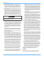
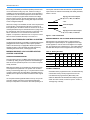
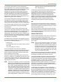
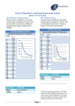
position of the guide vane. If the unit has a factory-installed
Variable Frequency Drive, the 2 to 10 VDC signal is wired from
VFD+/- output directly to the VFD’s signal input terminals to
control fan motor speed.
Table 2: Input Signal to Y1 Actuator Position
Input Signal to Y1
Actuator Position
10 VDC
90 degrees
9
78
8
67
7
56
6
45
5
33
GV1-3 - Monitoring that voltage is being supplied to gas valves
on optional heat stages.
4
22
3
11
LIM1-3 - Overtemperature inputs from optional heat stages.
2
0
0
-5
FILT - Dirty Filter switch [customer supplied, field installed on
factory-provided harness connections] input to provide a filter
status to the control. The control will alarm only after 24V has
been sensed for ten minutes.
FSI - Freeze Stat is a customer installed temperature switch on
the FSI input to the controller to tell the control that a
temperature has occurred that risks the hot water or steam coil.
Y1-4, W1-3 - If a thermostat is installed on the system, these
inputs will take priority over software programmed setpoints and
limits.
SD - This terminal set allows attachment of an external
shutdown NC contact. 24VAC power is supplied to the board at
SD2; a factory installed jumper passes that power to terminal R
to power the Simplicity Elite™ board. If an external shutdown
signal is required at a particular installation, remove the jumper
and connect the NC shutdown circuit between SD1 and R.
8VDC over a 90 degree Span = 11.25 degrees/VDC
VFD
FR
Simplicity
Fan
12
18
P13-1
FR
TB2
VFD +
VFD -
Wht
P14-1
P14-2
Blk
53
55
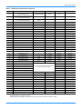
OUTPUTS
Analog Outputs (AO) - Analog outputs provide a 2-10 VDC
signal to operate controlled devices. The Simplicity® is currently
configured to use only 2-10 VDC outputs to the Variable
Frequency Drive, Inlet Guide Vane, Economizer Damper,
Power Exhaust Dampers or VFD, and Heating water valves.
Since these outputs are analog, they are continuous between 2
and 10 Volts and are proportional to the 0 to 100% drive
position of the device.
ECO - Economizer Actuator - The modulating Economizer uses
a Johnson Controls M9220GGAYK30 spring-return actuator
(PN: 025-30869-000A). This actuator uses a 2-10 VDC signal
to drive the dampers open. The actuator drives 95 degree
rotation. Note the chart below for a correlation between the
input drive signal at terminal 3 (Y1) of the actuator and the
corresponding output drive position of the damper:
VFD - Inlet Guide Vane or VFD - The Inlet Guide Vane uses a
Johnson Controls M9220GGAYK30 spring-return actuator. This
actuator uses the 2-10 VDC signal from VFD+/- terminals to
drive the dampers open. The actuator drives 95 degree rotation.
Note the chart below for a correlation between the input drive
signal at terminal 3 (Y1) and the corresponding output drive
8
Figure 4: VFD Control Wiring
EXD - Power Exhaust Damper Vane or VFD - Power Exhaust
Damper Actuator is a Johnson Controls M9220GGAYK30. It
uses a full open/ Full Closed scheme and operates a 95 degree
rotation. If VFD Power Exhaust is configured, the same signal
controls the exhaust fan motor drive frequency.
HWV - Heating Water Valve - Customer supplied and installed,
connect to factory-provided harness.
BINARY OUTPUTS (BO)
FAN - Fan Start/Stop Relay, VFD “permission” relay FR
H1-3 - HEAT STAGES 1 TO 3 [OPTIONAL]
C1 through C4 - Cooling Stages 1 through 4
CF1 & CF2 - Condenser Fan Banks 1 and 2
X - Controller Alarm is field-wired from the thermostat interface
board to signify a controller alarm has occurred.
Johnson Controls Unitary Products
351579-YTS-C-0111
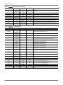
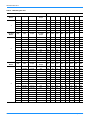
Table 3: Simplicity® Control Inputs
Name
Range
Resolution
Precision
Y1
18 - 30 VAC
On - Off
+/- .5 VAC
Request for the first stage of Cooling (24 VAC sense) Tstat Screw Terminal
Description
Y2
18 - 30 VAC
On - Off
+/- .5 VAC
Request for the second stage of Cooling (24 VAC sense) Tstat Screw Terminal
Y3
18 - 30 VAC
On - Off
+/- .5 VAC
Request for the third stage of Cooling (24 VAC sense) Tstat Screw Terminal
Y4
18 - 30 VAC
On - Off
+/- .5 VAC
Request for the fourth stage of Cooling (24 VAC sense) Tstat Screw Terminal
W1
18 - 30 VAC
On - Off
+/- .5 VAC
Request for the first Stage of Heating (24 VAC sense) Tstat Screw Terminal
W2
18 - 30 VAC
On - Off
+/- .5 VAC
Request for the second Stage of Heating (24 VAC sense) Tstat Screw Terminal
W3
18 - 30 VAC
On - Off
+/- .5 VAC
Request for the third Stage of Heating (24 VAC sense) Tstat Screw Terminal
G
18 - 30 VAC
On - Off
+/- .5 VAC
Request for the Fan (24 VAC sense) Tstat Screw Terminal
R
18 - 30 VAC
-
-
C
Earth Ground
-
-
OCC
18 - 30 VAC
On - Off
+/- .5 VAC
These terminals are a ¼' Female Faston and a Thermostat Screw terminal
connected to the power supply of the board.
These terminals are a ¼' Faston and a Thermostat Screw terminal.
Occupied input (24 VAC sense) Tstat Screw Terminal
SD
18 - 30 VAC
-
+/- .5 VAC
Shut Down input Tstat Screw Terminal
Purge
18 - 30 VAC
On - Off
+/- .5 VAC
Building Purge input (24 VAC sense) Tstat Screw Terminal
BAS Economizer
2 - 10 VDC
Not Read by micro
-
HPS1
18 - 30 VAC
On - Off
+/- .5 VAC
High Pressure Switch for Circuit # 1 (24 VAC sense)
HPS2
18 - 30 VAC
On - Off
+/- .5 VAC
High Pressure Switch for Circuit # 2 (24 VAC sense)
HPS3
18 - 30 VAC
On - Off
+/- .5 VAC
High Pressure Switch for Circuit # 3 (24 VAC sense)
HPS4
18 - 30 VAC
On - Off
+/- .5 VAC
High Pressure Switch for Circuit # 4 (24 VAC sense)
LPS1
18 - 30 VAC
On - Off
+/- .5 VAC
Low Pressure Switch for Circuit # 1 (24 VAC sense)
LPS2
18 - 30 VAC
On - Off
+/- .5 VAC
Low Pressure Switch for Circuit # 2 (24 VAC sense)
LPS3
18 - 30 VAC
On - Off
+/- .5 VAC
Low Pressure Switch for Circuit # 3 (24 VAC sense)
LPS4
18 - 30 VAC
On - Off
+/- .5 VAC
Low Pressure Switch for Circuit # 4 (24 VAC sense)
Limit Switch 1
18 - 30 VAC
On - Off
+/- .5 VAC
High Limit Switch input (24 VAC sense) For Burner section 1
Limit Switch 2
18 - 30 VAC
On - Off
+/- .5 VAC
High Limit Switch input (24 VAC sense) For Burner section 2
Limit Switch 3
18 - 30 VAC
On - Off
+/- .5 VAC
High Limit Switch input (24 VAC sense) For Burner section 3
GV1
18 - 30 VAC
On - Off
+/- .5 VAC
Gas Valve input (24 VAC sense) For Burner section 1
GV2
18 - 30 VAC
On - Off
+/- .5 VAC
Gas Valve input (24 VAC sense) For Burner section 2
GV3
18 - 30 VAC
On - Off
+/- .5 VAC
Gas Valve input (24 VAC sense) For Burner section 3
Test / Reset / Up
ON - Off
ON - Off
-
Address / Down
ON - Off
ON - Off
-
Address Button and Decrement Data Input
Alarms / Advance Data
ON - Off
ON - Off
-
Alarm Button and Advance Data Input
Program
ON - Off
ON - Off
-
Program Button Input
Real Time Clock
24 hours, 365 Days
including Leap year
and Daylight
Savings Time
Seconds
-
Real Time Clock Chip
Water Coil Freeze Stat
(FSI)
18 - 30 VAC
On - Off
+/- .5 VAC
This is a 10K type 3 Thermistor
Input that routes to the Economizer output Two Tstat Screw Terminals +&-
Test / Reset Button and Increment Data Input
Hot Water Freeze Stat (24 VAC sense) two ¼ Fastons
Supply Air Temp Sensor
(SAT)
-40° - +180° F
.1° F
-40° - 180 °F
+/- 2 °F across
range
Outside Air Temp Sensor
(OAT)
-40° - +180° F
.1° F
-40° - 180 °F
+/- 2 °F across
range
This is a 10K type 3 Thermistor
Space Temp Sensor
(ST)
32° - 100° F
.1° F
.5° F
This is a 10K type 3 Thermistor
Return Air Temp Sensor
(RAT)
-40° - +180° F
.1° F
-40° - 180 °F
+/- 2 °F across
range
This is a 10K type 3 Thermistor
Space Setpoint Offset
(SSA)
0 - 20 K
1 K
+ and - 250
3 position Mini Screw Terminal shared with Space Temp The common terminal
in the center is common for both the Space Temp and Setpoint Offset.
Building Pressure
Sensor
(BPS)
0 - 5 VDC-.25 - +.25
"WC
.001 "WC
.005 "WC
1% Across range
Duct Pressure Sensor
(DPS)
0 - 5 VDC0 - 5 "WC
.01 "WC
.05 "WC 1%
across range
APS (APS)
18 - 30 VAC
On - Off
+/- .5 VAC
Air Proving Switch (24 VAC sense)
Fan Overload (FOVR)
18 - 30 VAC
On - Off
+/- .5 VAC
Fan Overload Switch (24 VAC sense)
CV / VAV Input
0 - 20 K
1
+/-5
Johnson Controls Unitary Products
0 - 5 volt input
0 - 5 volt input
Resistive Input 0 - 5.5K = CV 10K - 20K = VAV
9
351579-YTS-C-0111
Table 3: Simplicity® Control Inputs (Continued)
Name
Range
Resolution
Precision
Demand Ventilation
Input
0 - 10 VDC
0 - 2000 PPM
of CO2
Description
1 PPM
20 PPM
1% Across Range
Remote Control
0 - 10 VDC
.05 VDC
0.01
Dirty Filter Switch
(FILT)
18 - 30 VAC
On - Off
+/- .5 VAC
Low Voltage Detection
12 - 35 VAC
.1 VAC
.5 VAC
Return Air Humidity
(RAH)
0 - 5 VDC0 - 100%
RH
.05 VDC1% RH
.1 VDC
2% Across Range
Scaleable 0 - 10 volts Screw terminal two position Small screw terminal
Outside Air Humidity
(OAH)
0 - 5 VDC0 - 100%
RH
.05 VDC1% RH
.1 VDC
2% Across Range
Scaleable 0 - 10 volts Screw terminal two position Small screw terminal
Comm Port
128 nodes
See
Communications
-
Asynchronous Serial Port (RS485) three position Small screw terminal
24 VAC - Class 1
18 - 30 VAC
-
-
¼'' quick connect for power to the contactors through the Relays.
0 - 10 volt input
0 - 10 VDC Screw terminal two position Small screw terminal
This is the Dirty Filter Switch (24 VAC sense)
This input monitors the 24 VAC for Low Voltage Detection
Table 4: Simplicity® Control Outputs
Name
Range
Resolution
Precision
LED
On - Off
-
-
Description
Display
7 segment W/
Decimal Point
H1
Class 1 Relay
Contacts
-
-
Heat 1 contactor output (Relay Contacts - 24 VAC/120 VAC)
H2
Class 1 Relay
Contacts
-
-
Heat 2 contactor output (Relay Contacts - 24 VAC/120 VAC)
H3
Class 1 Relay
Contacts
-
-
Heat 3 contactor output (Relay Contacts - 24 VAC/120 VAC)
C1
Class 1 Relay
Contacts
-
-
Compressor number one contactor output
(Relay Contacts - 24 VAC/120 VAC)
C2
Class 1 Relay
Contacts
-
-
Compressor number two contactor output
(Relay Contacts - 24 VAC/120 VAC)
C3
Class 1 Relay
Contacts
-
-
Compressor number three contactor output
(Relay Contacts - 24 VAC/120 VAC)
C4
Class 1 Relay
Contacts
-
-
Compressor number four contactor output
(Relay Contacts - 24 VAC/120 VAC)
CF1
Class 1 Relay
Contacts
-
-
Condenser Fan contactor output (Relay Contacts - 24 VAC/120 VAC)
CF2
Class 1 Relay
Contacts
-
-
Condenser Fan contactor output (Relay Contacts - 24 VAC/120 VAC)
Fan
Class 1 Relay
Contacts
-
-
Fan contactor output (Relay Contacts - 24 VAC/120 VAC)
Exhaust Fan (EXH)
Class 1 Relay
Contacts
-
-
Exhaust Fan contactor output (Relay Contacts - 24 VAC/120 VAC)
Status LED
6 "Seven Segment LED /W decimal point"
Supply Fan VFD
2 - 10 VDC
-
-
This is a 2 - 10 volt output capable of 10 ma
Exhaust Fan Damper
(EXD)
2 - 10 VDC
.1 VDC
.1 VDC
This is a 2 - 10 volt output capable of 10 ma
Hot Water Valve
(HWV)
2 - 10 VDC
.1 VDC
.1 VDC
This is a 2 - 10 volt output capable of 10 ma
Hot Gas Reheat
2 - 10 VDC
.1 VDC
.1 VDC
This is a 2 - 10 volt output capable of 10 ma
Economizer (ECO)
2 - 10 VDC
.1 VDC
.1 VDC
This is a 2 - 10 volt output capable of 10 ma
X
24VDC
-
-
10
This is a 24VDC output for Alarms
Johnson Controls Unitary Products
351579-YTS-C-0111
SIMPLICITY® PROGRAMMING OPTIONS
The paragraphs below provide a definition of, and specify the
function related to, each of the parameters that are fieldadjustable using the interfaces available. The Millennium® Unit
is shipped from the factory with the necessary options preprogrammed as indicated by the model nomenclature. It is
always a good practice, though, to verify that the correct
parameters are properly configured for the unit you are
commissioning. You can find a complete list of field-adjustable
parameters in the “Settable System Parameters”.
setpoints that are specific to your customer’s needs (i.e.
building pressure) or enabling some extended options that are
integrated into the Simplicity control. Also, if there are field
changes, i.e. a modulating power exhaust option, the control
configuration will need to be modified for the new option.
METRIC OPERATION (ENGLISH)
The factory default for this option is OFF. The metric (SI)
conversions are part of the controller software; when the Metric
parameter is selected, temperature setpoints and readings will
convert to Centigrade (°C).
For a description of the parameters, see the Settable System
Parameters below and Table 5.
SETTABLE SYSTEM PARAMETERS
INTERACTING THROUGH THE MILLENNIUM®
SIMPLICITY®
The following headings list each parameter’s name and its
default setting. The control is set at the factory for the options of
the specific unit; if a replacement control is being installed, the
entire parameter set must be matched to the unit. The number
in (parentheses) is the value of a parameter in an un-configured
control.
SET THE CLOCK
• Power up the unit.
• Press the Program button [upper left].
• Press the Test/Up button [upper right]. Hold it in and it will
step through the parameters, or push in to advance one
parameter at a time. Advance to parameter 63, Hours.
• Press Change [lower left] Press Up [upper right] or Down
[lower right] to the correct hour [24 hour time].
• Press Change to enter the new value.
• Press Up to get to parameter 64, Minutes.
• Press Change.
• Press Up or Down to get to the correct minute value. Press
Change to enter the new value.
• If you are done changing parameters, press Program to
exit the program mode.
PARAMETER SETTING
The buttons allow the operator to go to a specific parameter and
to view and change the data in that parameter.
• To enter the parameter setting mode, press the Program
button. The control will display the current parameter number in the two-digit display, and the present value of that
parameter in the four-digit display.
• To change to another parameter, press the /Up or /Down
button to move to the address of the desired parameter.
The present value of that parameter will display.
• To change the data, press the /Change button. The value
will flash. While it is flashing, press the /Up or /Down button to increase or decrease the value.
• When the desired new value is showing, press the
/Change Data button again to tell the control to store the
new value. You can verify that the new value is in place
when the value stops flashing.
• To exit Program mode, press the Program button again.
INITIAL STARTUP OPTIONS
Commissioning a new Millennium® installation requires some
field adjustments to the Simplicity® control program. Most of
these adjustments simply involve setting up the various
Johnson Controls Unitary Products
Compressors - (2) - This tells the control the number of
compressors available. The Factory Default [the value in an
unconfigured replacement control] is 2 and can be adjusted
from 1 to 4.
Heat Stages - (2) - This tells the control the number of heating
stages available. This parameter may be set from 0 to 3. The
default setting is 2 stages of heat. When modulating gas heat is
installed the parameters is always set to 2.
Hydronic Heat - (OFF) - This tells the control that a Hot Water Coil
is installed. If the control is going to modulate the Hot Water Valve
it will also turn on the Heat One output. This is to energize the VAV
heat relay for the VAV boxes. The default is OFF for this option. If
this parameter is enabled, remember to set the Hydronic Heat First
and Second Stage Setpoints and the Economizer Loading
Setpoint found in the ”Simplicity® Setpoints”.
Stage 1 Hydronic Heat SAT Setpoint - (120 °F) - When the
Hydronic Heat option is enabled, the control will maintain this SAT
setpoint for a call for first stage Heating, by modulating the Hot
Water Valve. This is the reset temperature when operating a VAV
unit in the Heating mode. The reset range for SAT setpoint is from
80 °F to 180 °F with 120 °F shipped as the default.
Hydronic Heat Reverse Actuated Valve - (OFF) - This setting
is to allow convenient use of reverse acting water valves;
setting this parameter to (ON) will change the signal to 2VDC =
open, 10 VDC = closed.
SAT Control for Cooling - (ON) - This tells the control if it is
going to do excessive SAT monitoring and tripping or not, for
Cooling. The SAT should be maintained in an acceptable
range in order to achieve reliable compressor operation. The
compressor trip limits are user adjustable between 40 °F and
65 °F in one degree increments. The default cooling trip
limits are 50 °F for stages 2-4, and 45 °F for stage 1. When
the SAT drops below the trip limit for each respective
compressor, that compressor is locked out and a 5 minute
ASCD is initiated for that compressor. If this option is
enabled, remember to set the compressor cooling limits for
low limit trip.
11
351579-YTS-C-0111
Power Exhaust - (ON) - This tells the control if it has the Power
Exhaust option installed.
Economizer Damper Position for Exhaust Fan to turn ON
(Non-Modulating PE Only) - (60%) - This tells the control the
Economizer Damper position to turn on the Exhaust Fan. This
value is based on the 0%-100% output drive signal from the
controller to the economizer damper actuator.
Economizer Damper Position for Exhaust Fan to turn OFF
(Non-Modulating PE only) - (20%) - This tells the control the
Economizer Damper position to turn off the Exhaust Fan. This
value is based on the 0%-100% output drive signal from the
controller to the economizer damper actuator.
Modulating Exhaust - (OFF) - This tells the control if the
Power Exhaust is Modulating or not. A modulating exhaust will
be equipped with a Building Pressure Sensor [BPS]. A NonModulating exhaust will look to the economizer damper position
to energize the EXD output. If the sensor gets disconnected, or
fails, an alarm is set. The alarm can be turned off by correcting
the sensor problem (or; by turning off this option). The control is
not in this case self-configuring. It will not automatically use the
Building Pressure Sensor if the sensor is connected.
Exhaust VFD Installed - (OFF) - If the unit has a VFD, the EXD
output will be enabled when the supply fan is ON.
Exhaust Damper Position For The Exhaust Fan To Turn On
(Modulating Only) - (80%) - This tells the control the Exhaust
Damper position at which to turn on the Exhaust Fan. This
value is based on the 0%-100% output drive signal from the
controller to the damper actuator.
Exhaust Damper Position For Exhaust Fan To Turn Off
(Modulating Only) - (20%) - This tells the control the Exhaust
Damper position to turn off the Exhaust Fan. This value is
based on the 0%-100% output drive signal from the controller to
the damper actuator.
Building Pressure Setpoint - (+0.100”WG) - This is the
pressure setpoint the control will maintain when operating a
Power Exhaust. The Building Pressure Setpoint is adjustable
from -0.200”WG to +0.200”WG. The factory programmed default
is +0.100”WC. This setpoint is used when the exhaust control is
implemented as Proportional Control (with a Modulating Exhaust
Air Damper or VFD controlled from building static pressure), or
as a Two-position Control using building static (Power Exhaust
Fan controlled on-off from building static pressure).
Economizer - (ON) - This tells the control that there is an
Economizer Installed.
Economizer Min Position - (20%) - This tells the control what
the minimum outdoor damper position will be for the Occupied
mode. Adjustable from 0-100%, the Economizer Minimum
Position default is 20%.
Economizer First Stage Setpoint - (55 °F) - This tells the
control what Supply Air Temperature to maintain for a call for
first stage of cooling. This is used only during Constant Volume
cooling mode with Economizer operation. The setpoint is set at
55 °F with an adjustable range from 40 °F to 65 °F.
12
Economizer Second Stage Setpoint - (50 °F) - This tells the
control what Supply Air Temperature to maintain for a call for
second stage of cooling. This is used only during Constant
Volume cooling mode with Economizer operation. This setpoint
is set at 50 °F with a range from 40 °F to 65 °F.
Outside Air Humidity (OAH) Sensor Enable - (OFF) - This
setting tells the control that it is expected to use Outside Air
Enthalpy (calculated from Outside Air Temperature and Outside
Air Relative Humidity sensed values) to decide if Outside Air
can be used for cooling.
The control is self-configuring to the best available decision
strategy for free cooling availability. For example, if it detects
that OAT and OAH and RAT and RAH sensors are all
connected and reliable, will self-configure for Differential
Enthalpy operation. If one of the return air sensors should fail,
the control will reconfigure for Outside Enthalpy operation, etc.
If the OAH Sensor Enable option is turned ON, it means that the
Outside Enthalpy Operation, or better decision strategy, is
expected (and supported by installed sensors). If the
appropriate sensors are not installed, or one of them failed, a
sensor failure alarm is set. The alarm can be turned off by
turning off the OAH Sensor Enable option. Thus, the option
setting is used to reflect the desired operation and mainly to
control sensor failure alarms.
The option setting can be viewed as specifying that (the selfconfigured economizer decision strategy has to be at least this,
or better, otherwise an alarm is set). If the option is OFF, the
control still may self configure to Outside Enthalpy Operation, or
even to Differential Enthalpy Operation (if all needed sensors
are available), but this option setting will allow also the decision
strategy based on only OAT (in case other sensors fail, or are
not installed) without setting an alarm.
Outside Air Enthalpy Setpoint - (27 BTU/LB) - This tells the
control an outside air enthalpy limit. Below this limit, outside air
is available for cooling. See enthalpy chart. This parameter
uses a one BTU/LB hysteresis on each side of the limit. The
limit is preset to 27 BTU/ LB with an adjustable range from 10 to
50 BTU/LB.
Return Air Humidity (RAH) Sensor enable - (OFF) - This tells
the control that it will compare Outside Air Enthalpy (calculated
from Outside Air Temperature and Outside Air Relative
Humidity sensed values) and Return Air Enthalpy (calculated
from Return Air Temperature and Return Air Relative Humidity
sensed values). The control will use the air stream with the
lower enthalpy for cooling.
The control is self-configuring to the best available decision
strategy for free cooling availability. For example, if it detects that
OAT and OAH and RAT and RAH sensors are all connected and
reliable, will self-configure for Differential Enthalpy operation. If
one of the return air sensors should fail, the control will stop using
rules that involve RAH and set an alarm.
If the RAH Sensor Enable option is turned ON (and supported
by installed sensors), Differential Enthalpy Operation can be
enabled. If the appropriate sensors are not installed, or one of
them failed, a sensor failure alarm is set. The RAH alarm can
Johnson Controls Unitary Products
351579-YTS-C-0111
be turned off by turning off the RAH Sensor Enable option.
Thus, the option setting is used to reflect the desired operation
and mainly to control sensor failure alarms.
Economizer Loading to Control SAT - (ON) - This tells the
control if it is going to use Economizer Loading to control
excessive SAT [supplying warmer outside air to keep SAT from
going too low]. This parameter is only applicable outside the
normal Economizer operation. During the Economizer
operation, the loading function is always performed and is an
integral part of the control algorithm.
Duct Static Setpoint - (1.5”WG) - This parameter is applicable
only to VAV mode of operation. This is the pressure setpoint that
the control will maintain when operating the fan in a VAV unit.
This setpoint is adjustable between 0”WG and 5”WG with the
default set to 1.5”WG.
Duct Static High Limit Setpoint - (4.5”WG) - This parameter is
applicable only to VAV mode of operation. This tells the control at
what Static Pressure to shut down the unit due to a Fan control
failure. This setpoint is to insure that we don't continue to operate
the Fan with an Inlet Guide Vane or VFD problem that could
cause the ductwork to fail from duct pressure. When the Static
Pressure reaches this setpoint (4.5”WG default), the control will
drive the supply fan control output to zero. If the static pressure
does decrease below the “Duct Static High Limit Setpoint” within
3 seconds after decreasing the supply fan control output to zero,
the control will resume normal operation. If there is no change in
static pressure after 3 seconds, the control will generate a High
Duct Static alarm, shut down all the outputs including the Fan and
shut down the unit. The alarm is written to the Error History Buffer
and will trigger storing a snapshot of Points Screen data along
with a date and time stamp. In networked applications, the alarm
flag is readable by the network. This parameter can be adjusted
from 0”WG to 5”WG with the factory default set to 4.5”WG.
The customer must be aware of the duct pressure design limit,
and what the duct pressure sensor will be reading when the peak
pressure is reached [the pressure pickup tube may not have
been located at the place of highest pressure in the system].
The alarm must be reset (after the problem that caused the
alarm is corrected) by resetting the controller by turning power
to the unit off and back on, or by reset command issued by an
external connection.
Morning Warm Up - Is inferred from the entries in
Occupied/Unoccupied
Occupied - (from settings in Weekly Schedule and Holiday
Schedule Tables 11 and 12.) - See discussion in Sequence of
Operation.
Unoccupied - (from settings in Weekly Schedule and Holiday
Schedule Tables 11 and 12.) - See discussion in Sequence of
Operation.
VAV High Temperature SAT Setpoint for Cooling - (60 °F) The control will maintain this SAT when operating in VAV mode
with a thermostat that is calling for first stage cooling. This
parameter may be adjusted from 40 °F to 70 °F with 60 °F set
as the default value.
Johnson Controls Unitary Products
VAV Low Temperature SAT Setpoint for Cooling - (55 °F) The control will maintain this SAT when operating in VAV mode
with a thermostat that is calling for second stage cooling. This
parameter may also be adjusted from 40 °F to 70 °F with 55 °F
set as the default value.
VAV SAT Reset Setpoint - (72 °F) - This parameter is used
only in VAV mode with a Space Sensor. The control will switch
from the VAV Lower Cooling SAT Setpoint to the VAV Upper
Cooling SAT Setpoint when this Space Temperature Setpoint
minus 0.5 °F is reached. The control will switch from High
setpoint back to Low setpoint when the space temperature gets
2 °F above this setpoint. This is SAT reset based on Space
Temperature. The reset occurs in both Occupied and
Unoccupied modes and may be adjusted from 40 °F to 85 °F.
The factory default is 72 °F.
VAV Occupied Heating - (OFF) - This option applies in VAV
mode with a Space Sensor and does not affect VAV Occupied
heating if requested by a thermostat. When this option is
toggled on, a VAV unit is able to operate heating in the occupied
mode as long as it is operating with a Space Sensor. If the
Space Temperature drops to 2 °F below the VAV SAT Reset
Setpoint the control will read the RAT. If the RAT is below the
Morning Warm Up RAT Setpoint the unit will enter the Occupied
Heating mode. Operation is the same as Morning Warm Up.
This parameter is factory set to OFF.
Comfort Ventilation Mode - (OFF) - Comfort Ventilation is a
SAT control mode that controls SAT during “satisfied” periods in
a fairly wide temperature band, using mostly Outside Air, and
also cooling and heating stages as necessary. It is available
only on the Constant Volume unit.
To enable Comfort Ventilation, the programmable parameter
“Comfort Ventilation Mode” must be set to ON (default setting is
OFF).
For a detailed explanation of Comfort Ventilation, refer to the
Sequence of Operation in this manual.
Comfort Ventilation High Supply Air Setpoint - (80 °F) - This
is the High Limit Setpoint for the Comfort Ventilation mode. For
a stable operation of Comfort Ventilation function, the High
Supply Air Setpoint should be set 10.0 °F or more above the
Low Setpoint.
Comfort Ventilation Low Supply Air Setpoint - (70 °F) - This
is the Low Limit Setpoint for the Comfort Ventilation mode. For
a stable operation of Comfort Ventilation function, the Low
Supply Air Setpoint should be set 10.0 °F or more below the
High Setpoint.
Dirty Filter Switch - (OFF) - This tells the control that a Dirty
Filter Switch is connected to it. The control will wait for ten
minutes after the switch has closed before declaring a Dirty
Filter Alarm. The alarm is written to the Error History Buffer. In
networked applications, the error flag is readable by the
network. The alarm will automatically reset when the error
condition is corrected.
The default is OFF.
13
351579-YTS-C-0111
Heating Lockout on OAT - (75 °F) - This is the Outside Air
Temperature Setpoint that the control will use to lock out Heating
when the OAT is above this setpoint. There is a one-degree
hysteresis on each side of the setpoint. This parameter is
adjustable between 0 °F and 100 °F with the default set to 75 °F.
Heating Lockout on OAT affects only staged heating, it does not
affect hydronic heat. If the heating is energized when OAT
reaches this setpoint, the Status LED will indicate the lockout
condition immediately, but the control will finish the heating
mode and then lock out the heating.
Note that a Heating Lockout on OAT may occur while the
control is in a heating mode and there is a demand for heating.
If the OAT then decreases below the lockout setting while the
call for several heat stages exists, the heat stages will turn on
simultaneously. This is considered acceptable as this situation
is not expected to occur frequently.
Cooling Lockout on OAT - (45 °F) - This is the Outside Air
Temperature Setpoint that the control uses to lock out Cooling
when the OAT is below this setpoint. Adjustable from 0 °F to
100 °F, the default is 45 °F.
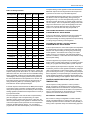
Unoccupied Heating Setpoint - (60 °F) - This value is the
Unoccupied Heating Setpoint. It is used in both CV and VAV
mode of operation (in VAV, it controls Unoccupied heating with
a Space Sensor).
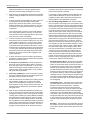
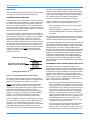
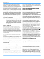
UnOcc.
Htg.
Occ.
Htg.
UnOcc.
Clg.
Occ.
Clg.
Figure 5: Sequence Of Setting The Set Points
The control will attempt to correct wrong temperature overlap
settings; for example, if a change is made that would put
Occupied Heating above Occupied Cooling, the Occupied
Cooling setting will change to stay above the heating setpoint.
Occupied Heating Setpoint - (68 °F) - This value is the
Occupied Heating Setpoint. It is used only in CV mode of
operation. Its relationship to the related setpoints is as defined
in the Unoccupied Heating Setpoint paragraph above.
Unoccupied Cooling Setpoint - (85 °F) - This value is the
Unoccupied Cooling Setpoint. It is used in both CV and VAV
mode of operation (in VAV, it controls Unoccupied cooling with a
Space Sensor).
Occupied Cooling Setpoint - (72 °F) - This value is the
Occupied Cooling Setpoint. It is used only in CV mode of
operation. Its relationship to the related setpoints is as defined
in the Unoccupied Heating Setpoint paragraph above.
[Input] FSI (Hot Water Freeze Protection) - (OFF) - This
option is used only on rooftop units with hydronic heat
(Hydronic Heat Option is turned ON). Freeze protection should
14
always be placed on units that use hydronic heating. When the
control senses 24VAC, the control will turn on the Hot Water
valve to 100%. The control will continue to drive the valve at
100% until five minutes after the switch has opened. Then the
valve will revert to normal operation. If the control is operating
the Fan, it will close the Economizer fully until the freeze
condition is over. If the fan is off and the RAT drops below 40 °F,
the Hot Water Valve will turn on 100%.
Supply AirTemp (SAT) Alarm Setpoint for Cooling - (0 °F) - If
the SAT does not drive below this setpoint when all stages of
compression are operating and 10 minutes has elapsed since
the last compressor was energized, the control will declare a
Cooling SAT Failure Alarm.
The alarm is written to the Error History Buffer. In networked
applications, the alarm flag is readable by the network.
The alarm will reset automatically if the SAT does decrease
below the setpoint (the alarm condition no longer exists), or
when a compressor is turned off (the control does not request
all compressors operate). The SAT Alarm Setpoint for Cooling
can be adjusted from 50 °F - 80 °F. If the value is set to 0 °F
(default) this feature is disabled.
Before the control declares an error, it will read the OAT and the
Economizer position. If the OAT is more than 20 °F warmer than
the setpoint and the Economizer is open more than 20%, the
control will close the Economizer for 10 minutes and then read
the SAT. If the SAT falls below the setpoint, the control will
declare an Economizer Minimum Position alarm. The control
will keep the Economizer closed and finish the Cooling mode.
After the Cooling mode has been satisfied, the control will move
the Economizer back to the minimum position.
Supply Air Temp (SAT) Alarm Setpoint for Heating - (0 °F) The SAT must drive above this setpoint when all stages of heating
are operating and 10 minutes has elapsed since the last stage was
energized. If this does not happen, the control will declare a
Heating SAT Failure Alarm. The alarm is written to the Error
History Buffer. In networked applications, the alarm flag is readable
by the network. The alarm will reset automatically if the SAT does
increase above the setpoint (the alarm condition no longer exists),
or when a heating stage is turned off (the control does not request
all heat stages to operate).
The SAT Alarm Setpoint for Cooling can be adjusted from 70 °F 120 °F. If the value is set to 0 °F (default) this feature is disabled.
Before the control declares an error, it will read the OAT and the
Economizer position. If the OAT is more than 20 °F colder than
the setpoint and the Economizer is open more than 20%, the
control will close the Economizer for 10 minutes and then read
the SAT. If the SAT rises above the setpoint, the control will
declare an Economizer Minimum Position alarm. The control
will keep the Economizer closed and finish the Heating mode.
After the Heating mode has been satisfied, the control will move
the Economizer back to the minimum position.
Unoccupied Override Time Period - (60 min) - The
Unoccupied Override Time Limit function will determine how
long the unit will operate in the Unoccupied Override mode
when the Override button is pressed on the Space Sensor.
Johnson Controls Unitary Products
351579-YTS-C-0111
Once the Unoccupied Override mode is initiated, it will continue
until the programmed Unoccupied Override Time Limit is
reached. The Override mode can not be cancelled by, for
example, a change of state of the Occupied input to ON
(occupied) and then back to OFF (unoccupied).
This parameter is adjustable from 0 to 240 minutes. The default
is 60 minutes.
Fan Delays (ON) & (OFF) - Any time the control starts a
compressor it will load the Fan On Delay for Cool with the
programmed value. Any time the control turns off all the
compressors it will load the Fan Off Delay for Cool with the
programmed value.
When the control turns on a gas heat stage, it will begin
monitoring the gas valve and load the Fan On Delay For Heat
with the programmed value when it senses gas valve voltage. If
modulating gas heat is installed, then Fan Off Delay in heating
must be set to Off.
When the thermostat terminates the call for W1 the control will
turn off H1 output and load the Fan Off Delay for Heat with the
programmed value.
After the control has turned on heat, it will start monitoring the
Gas Valve. If at any time the Gas Valve (24 VAC) is not present
for five minutes while H1 is on, the control will flag an Alarm.
Anytime GV1/H1 goes off during the fan on delay, the control
will force the fan on, for the fan off delay period. The control will
wait for GV1 to be on at least 15 seconds before forcing the fan
on. If GV1 has been on for at least 15 seconds, and then goes
away before the Fan On Delay has finished, the fan will turn on
anyway far a length of time equal to the Fan Off Delay period.
IAQ Sensor Range - (5,000 ppm) - This tells the control what
the full range is for a specific IAQ sensor. It can be changed
from 0 to 10,000 ppm.
Cooling Mode Enable (ON) - This tells the control if it has
Cooling Available (Mode Switch). If this option is turned off,
cooling operation is disabled. Note that this parameter does not
affect cooling operation in Comfort Ventilation mode.
Heating Mode Enable - (ON) - This tells the control if it has
Heating Available (Mode Switch). If this option is turned off,
heating operation is disabled. Note that this parameter does not
affect heating operation in Comfort Ventilation mode.
Space Setpoint Offset - (3 °F) - The Space Setpoint Offset is
the +/- value the control will use to offset the Space Setpoint
when the slidebar Space Sensor is used. For example, if the
Space Setpoint Offset value is set to 3.0 °F, shifting the slidebar
all the way in minus direction will decrease the Space Setpoint
by 3.0 °F and shifting it all the way in plus direction will increase
the Space Setpoint by 3.0 °F. It is adjustable from 0 °F to 5 °F.
ASCD Override - This is not an option parameter but rather a
one-time command issued by pressing the Test / Reset / Up
button pressed and released within five seconds; the ASCD’s
will be set to zero for one cycle.
Run Test (Commissioning Test) - This is not an option
parameter but rather a one-time command, activated by setting
parameter 1 ON.
When the Run Test command is issued, the control will shut the
unit down if it is running and then start a Run test sequence:
1.
Turn on the Fan and then turn on all the compressors, one
at a time, with a 15-second delay between them. Condenser fan #1 turns on with compressor #1, condenser fan
#2 turns on with compressor #2. After the last compressor
has been turned on, the control will run the compressors
for the programmed minimum run time and then turn them
all off. Condenser fans are also turned off.
2.
The control will then turn on the Heat stages, one at a time,
with a 15 second delay between them. The control will run
each Heat stage for three minutes and then turn all the
Heat off.
3.
The control will then open the Economizer to the 100%
open position and wait five minutes before closing it to the
Minimum Position. When the economizer is at 100%, the
exhaust damper will be open to 100% and the exhaust fan
runs for 5 minutes, then shuts down.
4.
During this Run Test operation the control will read all the
installed sensors and verify that their readings are good. If
any error is detected the control will display the appropriate
error. During the Run Test, the supply fan continues to be
monitored via the Air Proving Switch, and a fan failure will
cause a unit shutdown.
If the control senses this input along with a Y signal, it will not
turn on the compressors and it will run the Heating mode.
Heating takes priority.
Fan ON Mode with the Sensor Option - (ON) - When this
option is turned ON, the supply fan will continue running when
the zone sensor based temperature control is satisfied. This
option applies only in systems using a zone sensor and only in
Occupied mode. With this option turned OFF, or in Unoccupied
mode, the fan will go off when the zone sensor based
temperature control is satisfied and will go on only when there is
a call for heating or cooling. Turning this option ON is an
equivalent of selecting fan ON (rather than AUTO) in systems
with a thermostat. In a thermostat system, the fan control follows
the thermostat's G signal. In sensor systems and in the Occupied
mode, the fan control follows the Fan ON Mode option.
Space Sensor Enable - (OFF) (INTERNALLY SET) - The
control will use this input if it detects the device.
RAT Sensor Enable - (OFF) (INTERNALLY SET) - The control
will use this input if it detects the device.
Demand Ventilation (ON) - Setting this parameter on tells the
control to expect a signal from a 0-10VDC CO2 sensor. The
default setting for CO2 is 1,000 ppm.
Demand Ventilation Setpoint - (1000 ppm) - This Setpoint is
the maximum Indoor Air Quality (IAQ) level that the control will
allow. It is adjustable from 700 ppm to 1500 ppm.
Johnson Controls Unitary Products
After the control is finished with the Run Test the normal
operation will resume. This command is a good method to use
to ensure the control is operating and all input and output points
are functional.
15
351579-YTS-C-0111
Table 5: Settable System Parameters
16
Address
Function
1
Run test
2
Fan on delay-Heating
3
Fan off delay-Heating
4
Unit
Range
Default
ON-OFF
OFF
Sec
0-30
30
Sec
0-255
60
Fan on delay-Cooling
Sec
0-30
0
5
Fan off delay-Cooling
Sec
0-255
30
6
Factory setting
-
-
1
7
Suspend Cont Fan when starting Heating
ON-OFF
OFF
OFF
8
Construction Mode
-
ON-OFF
9
Unoccupied Override Time Period
Minutes
0-240
60
10
Occupied Cooling Setpoint
°F
45-99
72
68
11
Occupied Heating Setpoint
°F
45-99
12
Unoccupied Cooling Setpoint
°F
45-99
85
13
Unoccupied Heating Setpoint
°F
45-99
60
14
SAT Control-Cooling
ON-OFF
ON-OFF
ON
15
Cooling SAT Control Setpoint
°F
40-65
50
16
SAT Control for Heating
ON-OFF
ON-OFF
ON
17
Heating SAT Control Setpoint
°F
100-180
135
18
Hydronic Heating
ON-OFF
ON-OFF
OFF
19
First Stage Hydronic Heating SAT Setpoint
°F
80-180
120
20
Second Stage Hydronic Heating SAT Setpoint
°F
80-180
150
21
Hydronic Heating Reverse Actuated Valve
ON-OFF
ON-OFF
OFF
22
Remote Control
ON-OFF
ON-OFF
OFF
23
VAV Upper Cooling SAT
°F
40-70
60
24
VAV Lower Cooling SAT
°F
40-70
55
25
VAV SAT Reset Setpoint
°F
40-85
72
26
VAV Occupied Setpoint
ON-OFF
ON-OFF
OFF
27
VAV Occupied Heating Setpoint
°F
40-85
68
28
Morning Warm-Up
ON-OFF
ON-OFF
ON
29
Morning Warm-Up RAT
°F
50-85
70
30
Duct Static Setpoint
" H2O
0 – 5”
1.5”
31
Building Pressure Setpoint
" H2O
neg .25 to .25
.1”
32
Economizer
ON-OFF
ON-OFF
ON
33
Economizer First Stage
°F
40-65
55
34
Economizer Second Stage
°F
40-65
50
35
Economizer Minimum Position
Percent
0 to 100%
20
OFF
36
Outside Air Humidity Sensor
ON-OFF
ON-OFF
37
Economizer Outside Air Enthalpy Setpoint
BTUs Per Pound
10-50
27
38
Return Air Humidity Sensor
ON-OFF
ON-OFF
OFF
39
Economizer OAT Enable
°F
40-80
55
40
Demand Ventilation
ON-OFF
ON-OFF
OFF
41
IAQ Sensor Range
PPM
0-5000
2000
42
Demand Ventilation Setpoint
PPM
0-5000
1000
43
Power Exhaust
ON-OFF
ON-OFF
ON
44
Modulating Exhaust
ON-OFF
ON-OFF
OFF
45
Exhaust VFD Installed
ON-OFF
ON-OFF
OFF
46
Exhaust Damper Position for Exhaust Fan to
Turn On (Modulating Only)
% Of Damper Position
0-100
80%
Your Settings
Do not change
Johnson Controls Unitary Products
351579-YTS-C-0111
Table 5: Settable System Parameters (Continued)
Address
Function
Unit
Range
Default
47
Exhaust Damper Position for Exhaust Fan to
Turn Off (Modulating Only)
% Of Damper Position
0-100
20%
48
Economizer Damper Position for Exhaust Fan
to Turn On (Non-Modulating Only)
% Of Damper Position
0-100
60%
49
Economizer Damper Position for Exhaust Fan
to Turn Off (Non-Modulating Only)
Percent of Economizer
Position
0-100%
20%
50
APS Data
Open-Closed
Open-Closed
Open
Your Settings
51
Dirty Filter Switch
ON-OFF
ON-OFF
OFF
52
Dirty Filter Switch Data
Open-Closed
Open-Closed
Open
53
Cooling Mode Enable
ON-OFF
ON-OFF
ON
54
Heating Mode Enable
ON-OFF
ON-OFF
ON
55
Fan On Mode with the Sensor Option
ON-OFF
ON-OFF
ON
56
Space Setpoint Offset
°F
-5 to 5
0 degrees
57
Metric Operation
ON-OFF
ON-OFF
OFF
58
BAS Economizer
ON-OFF
ON-OFF
OFF
59
Year
Year
00-99
4
60
Month
Month
Number
1
61
Day of Month
Day
Number
1
62
Day of Week
Day
Number
1
63
Hour
Hour
0-23
0
64
Minute
Minutes
0-59
0
65
SAT (Supply Air Temp)
°F
-40 to 180
Read Only
Read Only
66
RAT (Return Air Temp)
°F
-40 to 180
Read Only
Read Only
67
OAT (Outside Air Temp)
°F
-40 to 180
Read Only
Read Only
Read Only
68
ST (Space Temp)
°F
-40 to 180
Read Only
69
OAH (Outside Air Hum)
%RH
0 to 100%
Read Only
Read Only
70
RAH (Return Air Hum)
%RH
0 to 100%
Read Only
Read Only
71
Occupied Input Enable
ON-OFF
ON-OFF
72
Alarm Array
Read Only
Read Only
73
Alarm Array
Read Only
Read Only
OFF
These values represent the last 5 alarm codes in
memory. 72 is latest & 76 oldest.
74
Alarm Array
Read Only
Read Only
75
Alarm Array
Read Only
Read Only
76
Alarm Array
Read Only
Read Only
Read Only
Read Only
77
CV/VAV Mode
Read Only Flag
78
Hot Gas Reheat
ON-OFF
CV=0
ON-OFF
VAV=1
OFF
79
Hot Gas Bypass
ON-OFF
ON-OFF
OFF
80
Compressors
Number
2 to 4
Factory Set
81
Heat Stages
Number
0 to 3
Factory Set
82
Duct Static Reading
Inches Water
0 to 5.0”
Read Only
83
Building Pressure Reading
Inches Water
0 to 5.0”
Read Only
84
Low Ambient Kit Installed
ON-OFF
ON-OFF
Factory Set
85
Building Static Pressure Sensor Enable
ON-OFF
ON-OFF
Factory Set
86
ERV Installed
ON-OFF
ON-OFF
Factory Set
87
ERV Unoccupied Fan
ON-OFF
ON-OFF
Factory Set
88
Duct Static Shutdown Setpoint
Inches Water
0 to 5.0”
4.5”
NOTES:
For On/Off functions, 1 is ON and 0 is OFF
Read only items are readings from sensors which only change as the measured condition changes.
Johnson Controls Unitary Products
17
351579-YTS-C-0111
MILLENNIUM® SEQUENCE OF OPERATION
OVERVIEW
The Millennium® Simplicity® control has comprehensive rule
sets to respond to heat and cool calls, provide anti-shortcycle
and other safeties, date / time clock, and other features making
the programmable thermostat unnecessary. The Millennium®
Simplicity® extends on the rules of the Synthesys digital control.
With an attached (optional) Room Sensor, the control provides
calls for heating and cooling and occupied override. The control
determines when to start morning warm-up, mechanical
cooling, or heat based on parameter settings in the Millennium®
Simplicity® control, its internal time clock, Occupied and holiday
schedules, the deviation from the setpoints, and the rate of
temperature change.
A separate thermostat cannot determine if an output function is
available. For example, if the belts on the supply fan were to
break, the thermostat would still call for the fan to operate and,
if space conditions require, call for heating or cooling. Logic in
the control prevents undesired operation of heating and cooling
stages, with interlocks and minimum run times. Moreover, the
control can report faults on its digital display or on a network to
a monitoring system.
Control logic is designed such that airflow must be proven before
any heating or cooling stage can operate. Mechanical cooling is
locked out below 40 °F outdoor ambient for all units without head
pressure control. The control provides voltage to energize the
contactors for the supply fan, cooling stages, heating stages, and
options such as the economizer and power exhaust. The
thermostat makes calls for cooling and heating; the Simplicity®
control is responsible for executing the rules putting these calls into
action and protecting the unit through appropriate safety devices. If
the Millennium® Simplicity® senses low voltage, it will hold any
call that energizes a contactor until the voltage is adequate. It will
not alarm for low voltage, but will provide a flash code.
The control also energizes the supply fan and cooling stages
based on external inputs from the thermostat:
•
•
•
•
•
G - Supply Fan
Y1-1st Stage Cooling
Y2-2nd Stage Cooling
Y3-3rd Stage Cooling
Y4-4th Stage Cooling
Heating stages are controlled based on inputs:
• W1-1st Stage Heating
• W2-2nd Stage Heating
• W3-3rd Stage Heating
The economizer is enabled through settings in the control and
operating conditions, or external BAS calls.
RUN SEQUENCE
The unit operates in one of three modes: Occupied, Unoccupied,
and Recovery (Warm-up / Cool-down). The control allows none,
one, or two separate occupied / unoccupied schedules for each
18
day of the week, and twenty holidays. In addition to the
programmed schedule, the space sensor allows a single key
press to provide up to a 4-hour unoccupied override into the
occupied mode.
OCCUPIED MODE: The supply fan operates continuously in
the Occupied and Recovery modes. The thermostat cycles
cooling / heating to maintain the space temperature to the
Occupied setpoints. Simplicity® will enable optional economizer
and power exhaust features.
UNOCCUPIED MODE: The supply fan operates only with
cooling / heating calls. The economizer is disabled during the
unoccupied mode except when free cooling may be used to
condition the space. Cooling / heating stages are cycled to
maintain the space temperature to the Unoccupied setpoints.
RECOVERY MODE: A special unoccupied mode that allows
transition to occupied mode. The supply fan operates
continuously and the economizer remains disabled. Instead of
maintaining the unoccupied setpoints, the thermostat ramps the
space temperature toward the occupied setpoints. The
Millennium® Simplicity® control has an option for the control to
“learn” how long it takes to get the building to the desired
temperature, and adjust its start time to minimize the recovery
time. Refer to the Intelli-Start section.
UNIT CONTROLS SEQUENCE
If the thermostat gives a call for G fan, W heating, or Y cooling,
or the space sensor reading is not within the setpoint range; this
is acted upon by unit control according to the sequence outlined
below. A thermostat must not be connected anywhere but the
appropriate labeled terminals. Direct control of compressors
and heaters is not acceptable.
Abbreviations for various components correspond to the labels
on the wiring diagram.
1.
On a call for the supply fan, voltage at terminal G is acted on
by the control. If the supply fan overload is not tripped, voltage goes out from the FAN terminal on the control to either
contactor 5M (Supply Fan Motor Starter) or relay FR (permission-to-run for the Variable Frequency Drive). Power is
applied to the airflow proving switch (APS). If the supply fan
operates correctly (proper rotation), the pressure difference
between the supply fan section and the heating section
increases and APS closes to enable operation.
The air proving switch is monitored by the control 90 seconds after the fan is energized.
The control also monitors the supply fan overload. The
overload circuit is wired directly to the control, not in series
with the fan contactor. If the supply fan overload trips for
longer than 5 seconds, the control will shut down the unit. If
the trip clears within 15 minutes, the unit will log an error
and resume operation. If the overload trips three times in
two hours [or stays tripped longer than 15 minutes], the
control will shut the unit down and report an alarm. In a
VAV unit, the control will shut down the unit if the duct pressure shutdown setpoint is reached or exceeded.
Johnson Controls Unitary Products
351579-YTS-C-0111
2.
Mechanical cooling stages have two monitoring circuits:
low pressure and high pressure. They are connected to the
control through the LPSx and HPSx terminals. These allow
the control to track specific error alarms, and let the control
energize the next available compressor.
denser fan 1). On 25 ton units, condenser fan 2 (contactor
7M) is brought on by PS5 if discharge pressure on compressor 1 exceeds 280 psi R22 (360 psi R-410a). Fan 2
drops out if discharge pressure drops below 180 psi R22
(300 psi R410a); condenser fan 4 (contactor 9M) is brought
on by PS6 monitoring discharge pressure on compressor
2.
Table 6: Cooling Stage, R22 (R410a)
*
Call
Economizer
Mode
Mechanical
Cooling Mode
COOL 1
Economizer (N/A)
Compressor 1
COOL 2
Compressor 1
Compressor 2
COOL 3
Compressor 2
Compressor 3
COOL4
*Compressor 3
Compressor 4
4.
A control call for Compressor 2 powers contactor 2M
through terminal C2, and CF2 (fan 3) through CTB1- terminal 10 on 25 ton units. On 30 and 40 ton R22 (and all
R410a units), because fans 1 and 2 pull through coils for
both circuit 1 and circuit 2, the coil of contactor 7M (condenser fan 2) is powered in turn through either of condenser fan cycling switches PS5 or PS6, which enables
condenser fan 2 operation if the discharge pressure of
Compressor 1 or Compressor 2 exceeds 280 psi R22 (360
psi R410a).
5.
30 and 40 ton R22 (and all R410a units): A call for Compressor 3 powers contactor 3M (contactor, compressor 3)
from terminal C3. A call for Compressor 3 or 4 also powers
CTB1- terminal 14, second stage condenser fans (contactor 8M, condenser fan 3, and also contactor 9M, condenser
fan 4 - 40 ton only).
6.
40 Ton R22 (and all R410a units): A call for Compressor 4
powers the coil of contactor 4M from terminal C4, and also
makes a parallel CR3-2 call to condenser fans CF3(8M)
and CF4(9M) with contact CR4-2.
7.
Standard Gas Heat Option, Stage 1: A W1 call locks out
cooling and initiates the control logic for Heat 1. The supply
fan is engaged, at full speed if VAV-equipped. Once APS
(air proving switch) closes to acknowledge supply airflow,
power is supplied from terminal H1, which engages Ignition
Control 1 (IC1) at heat module terminal W. 24V is supplied
to IC1 at terminal R/24V, and to the overtemp limit switch
LS1, which opens only with excessive heat exchanger temperature, on each gas heat module. That switch is monitored by connecting each limit switch to the LIM1, 2, or 3
terminal at the Simplicity board. IC1 closes contacts to
engage Draft Motor 1. After motor starts, negative pressure
closes PS1, PS2 or PS3.
25 Ton R22 does not apply.
For units without optional head pressure control: If
the outside air temperature rises above 50 °F, the control
enables all mechanical cooling stages. If the outside air
temperature falls below 40 °F and the unit does not have
head pressure control, mechanical cooling stages are
locked out.
For units with head pressure control: The first and
second mechanical cooling stages are enabled when the
ambient temperature rises above 10°F. When the ambient temperature rises above 50°F, the third (on 30 and
40 ton R22 (and all R410a units)) and fourth (40 ton R22
only (and all R410a units)) stage mechanical cooling are
enabled. If the outside air temperature falls below 40°F,
mechanical cooling stages 3 and 4 (40 ton R22 only
(and all R410a units)) are locked out. If the outside air
temperature falls below 0°F, all mechanical cooling
stages are locked out. On units with optional heating,
any call for heating engages the supply fan. Operation of
heating is dependent upon the APS closure.
When all run rules are satisfied, cooling stages are available. A
call for first stage cooling, Y1, initiates the control rules for
cooling. When the control is satisfied [temperature, short
cycling timing, safety circuits, etc.], it sends voltage out terminal
C1 to contactor 1M for compressor 1. If compressor 1 is not
available, the control will start compressor 2 via C2 / 2M.
With safeties in normal state, IC1 will attempt ignition. IC1
provides direct spark ignition with flame verification, and
controls the GV1 gas valve through manual reset switch
RS1 (rollout switch). If RS1 has tripped, GV1 is locked out
and IC1 will electronically lockout after three failed ignition
attempts. The Simplicity control monitors voltage to the gas
valves through terminals GV1-3.
In Occupied mode, the economizer is enabled [if installed and
the parameter set in the control]; if free cooling is available, the
economizer will energize in place of the first cooling stage.
A thermostat call for second stage cooling powers terminal Y2,
third stage powers Y3 (30 and 40 ton R22 (and all R410a units))
and fourth stage powers Y4 (40 ton R22 (and all R410a units)).
These thermostat calls are entered into the control's logic, and
available cooling stages brought on to meet the demand.
When the W1 call is canceled, power is removed from IC1,
which directs IC1 to close GV1. As long as APS continues
to prove supply fan airflow, IC1 remains powered and
keeps the draft motor contacts closed for 30 seconds to
maintain the operation of Draft Motor 1 for a postpurge of
the heat exchanger.
NOTE: The economizer may function when all mechanical
cooling stages are locked out on low ambient.
3.
When the control calls for Compressor 1 (25 ton R22), or
Compressor 1 or 2 (30 and 40 ton R22 (and all R410a
units)), it will also call condenser fan CF1 stage 1 through
CTB1- terminal 13, powering the coil of contactor 6M (con-
Johnson Controls Unitary Products
8.
Standard Gas Heat Option, Stages 2 and 3: The Millennium Simplicity responds to W2 and W3 similarly to W1, if
the unit is equipped with second and third heat modules.
19
351579-YTS-C-0111
9.
Modulating Gas Heat Option: The modulating gas heat
option uses a slave control, “MFC” Modulating Furnace
Control, that receives the heat calls from the UCB and then
controls up to 17 Steps of gas heat in a similar manner.
10. Electric Heat Option: The Millennium® Simplicity® control
allows staging electric heat. On units with the Electric Heat
Option, a call for heat (W1) will initiate the main supply fan.
When the Simplicity® control is satisfied by the APS, it will
complete the circuit to the first stage of electric heat by energizing terminal H1. If additional heat is required, H2 will energize the second stage of electric heat [if the unit is so
equipped], and H3 the third stage [if the unit is so equipped].
Disconnect all power supplies before checking or
servicing the electric heat section.
All electric heat modules have an auto-reset primary limit,
monitored by the control, and non-restartable back-up limits. Dirty filters, broken belts, fan motor burn-out or running
this unit below 6,000 CFM will cause the limit to trip on the
auto-reset primary limit. In addition to the primary limit,
back-up limits may trip under these conditions. The backup
limits are one-trip devices and will have to be replaced
should they trip.
When a call for heat has been satisfied, the highest stage
running will be de-energized until all are de-energized.
11. Hot Water Heat Option: The unit will send a 2-10 VDC signal to drive a hot water valve.
12. Economizer Option: The control directly controls the position of the outside air / return air dampers through a 2-10
VDC signal from terminal ECO to ACT1 (economizer actuator). The economizer is enabled only in Occupied or Recovery mode, and after supply fan operation has been verified
(APS closed). When the supply fan is powered and there is
no Y1 call or if free cooling is unavailable, the control opens
the economizer dampers to the minimum position setting.
The actuator maximum opening speed is 150 seconds to
full open; the control moves the actuator at the rate of two
seconds for each one % it is opening, so full open from
closed would take 200 seconds. At entry to Occupied
mode, the economizer is typically opening from 0 to a minimum setting of 20%, which would take about 40 seconds.
In Unoccupied mode, the economizer will close to 0%.
With a Y1 call when the outside air is appropriate for free
cooling (see below), free cooling is used for first stage cooling. The control modulates the economizer dampers to
maintain a SAT setpoint plus or minus one degree.
The control uses one of three methods to determine when
free cooling is available. The method used is determined
by the unit options, which function as listed below.
20
Dry Bulb: The control relies on the RAT, OAT, and SAT
readings, connected to those terminals on the control.
Free cooling will be available until the outdoor temperature rises above the indicated temperature range. Free
cooling is disabled when the outdoor temperature rises
above the temperature range and cannot be enabled
until the outdoor temperature falls below the indicated
temperature range.
Single Enthalpy: The Outdoor Air Humidity Sensor is
connected to terminal OAH. When the outdoor enthalpy
is below the setpoint, free cooling is available.
Dual Enthalpy (Comparative/Differential Enthalpy):
Both the Outdoor Air Humidity [OAH] and the Return Air
Humidity [RAH] sensors are connected to the control.
When the outdoor air enthalpy is less than the return air
enthalpy, free cooling is available. The control will disable free cooling and force mechanical cooling when the
outside air temperature exceeds setpoints.
13. Power Exhaust Option with Modulating Dampers: The
power exhaust controls are enabled in Occupied or Recovery mode when the APS is satisfied. The building pressure
is sampled by a tube provided and installed by the customer at a location in the building, connected to the high
pressure port of the pressure transducer BPS. BPS provides a 0-5 VDC signal to the control, which compares the
reading to the pressure setpoint to control the exhaust
dampers. The exhaust damper vanes are modulated by
ACT2, from a signal from terminal EXD+. The exhaust
motor is energized by voltage at terminal EXH to contactor
10M when the dampers are driven above the ON setpoint
for damper open %.
The exhaust motor is powered OFF when the vanes reach
the OFF % point set in control parameters. When the power
exhaust is disabled, ACT2's spring return closes the exhaust
dampers and 10M opens to shut down the exhaust fans.
14. Power Exhaust Option with Variable Frequency Drive:
The power exhaust controls are powered through EXH /
10M with a call for the supply fan. Once powered, the BPS
sensor (Building Pressure sensor) sends a signal to terminal 53 of the VFD. The damper vanes are gravity-closed;
motor speed is continuously variable. See separate document for details on power exhaust VFD operation.
15. Non-modulating Power Exhaust Option: The power
exhaust motor is energized by EXH / 10M based on the
position of the Economizer damper settings in the control
parameters. Minimum run time is 10 seconds; minimum off
time is 60 seconds. The outlet pressure of the power
exhaust fan forces the barometric relief dampers open;
gravity closes the dampers when the exhaust fan is off.
VARIABLE AIR VOLUME UNIT (VFD & IGV)
OVERVIEW
The VAV units operate in one of three modes: Occupied,
Unoccupied, and Recovery. The unit operational mode is
Johnson Controls Unitary Products
351579-YTS-C-0111
determined by the status of the internal clock and the internal
schedules.
OCCUPIED / UNOCCUPIED / MORNING WARM-UP
OCCUPIED
In Occupied mode, all installed options enabled by the
parameter settings are available. The supply fan is operated
[controlled to the duct pressure setpoint if a VAV], optional unit
heating is available at full capacity, the optional power exhaust
system is enabled, the economizer outside air dampers go to
their minimum position or open for free cooling. This operation
continues until the unit enters Unoccupied mode. When the
control sees an Occupied override button push from the
thermostat or space sensor, it will go to Occupied mode for the
length of time set in the parameters, up to four hours. If the unit
is in Space Sensor operation, the fan will operate at full speed
[controlled to the duct pressure setpoint if a VAV].
A VAV standalone unit will run MWUP the first hour of the OCC
override signal, then go to Occupied. The supply fan will run
continuously.
MORNING WARM-UP [MWUP]
The unit enters a morning warm-up mode going in to the first
Occupied period of the control’s internal daily schedule. In this
mode, the supply fan is operated at full volume, optional unit
heating is engaged at full capacity if needed, the optional power
exhaust system is enabled, the economizer outside air dampers
close (return air dampers open), cooling is disabled, and
voltage is provided at H1 to signal the remote VAV boxes to
open. This operation continues until the return air temperature
exceeds the adjustable setpoint of the Morning Warm-up bulb
thermostat (MWUP).
The parameter for MWUP must be turned on. Without IntelliStart, MWUP will start one hour ahead of Occupied. Cooling will
not start until the Occupied mode starts. In MWUP, the control
will operate the fan and energize heat after monitoring RAT five
minutes after going into MWUP, or if RAT goes two degrees
below the MWUP setpoint.
UNIT CONTROLS
1.
UNOCCUPIED
In Unoccupied mode, the economizer goes to full closed; the
supply fan will only operate if there is a call for heating or
cooling [controlled to the duct pressure setpoint if a VAV]. If
heating is required, all installed stages will be energized.
When the unit is running in Occupied mode, the duct pressure controller, if that option is installed, is activated; the
optional power exhaust system is activated, power is
applied to the airflow proving switch (APS), and to the supply fan motor contactor (5M) to engage the supply fan. If
the supply fan operates correctly (proper rotation) the pressure difference between the supply fan section and the
heating section increases and APS closes to enable operation. The control waits 90 seconds for the fan to reach equilibrium, then looks at the APS.
The bypass VFD is a standard Variable Frequency
Drive packaged with a further set of contactors When
bypass mode is activated, contactors route power
around the VFD, connecting the indoor fan motor
direct to supply voltage. At this point the motor will go
to full RPM regardless of the duct pressure signal,
because the VFD is out of the loop, and there is a
potential for over pressuring the ducts.
For units without optional head pressure control: If the outside air temperature rises above 50 °F the control enables
all mechanical cooling stages. If the outside air temperature falls below 40 °F, then all mechanical cooling stages
are locked out.
The air balancer must set maximum duct static / CFM
to stay within a static pressure that the ductwork of that
installation can tolerate when the motor is at full RPM,
considering that the VAV boxes, if they are part of the
system, may not be full open.
If the duct system includes VAV boxes, they must be
driven open in Bypass mode in the same manner as
going to heat mode. The drive indicates being in “bypass”
mode with normally open contacts wired to terminal block
1, position 5 and 6 across Danfoss relay M3 [refer to
drawings supplied by Danfoss, packed with the unit].
Voltage sufficient to signal the boxes to open must be
wired through this contact. This is a field-install
connection.
Johnson Controls Unitary Products
The control reviews parameters, the unit clock, and occupied /
Holiday schedules to select the appropriate mode. In Occupied mode, the unit will look at inputs enabled by parameter
settings. It will default to secondary inputs if necessary.
For units with head pressure control: Enable third and
fourth (40 Ton only) stage mechanical cooling when the
ambient temperature rises above 50 °F. If the outside air
temperature falls below 40 °F, mechanical cooling stages 3
and 4 (40 Ton only (all R410a)) are locked out. Enable first
and second stage mechanical cooling when the ambient
temperature rises above 10 °F. If the outside air temperature falls below 0 °F, all mechanical cooling stages are
locked out.
2.
While the return air temperature remains below the setpoint of MWUP (Morning Warm-up), engage the unit heat
(optional) at full capacity.
For Inlet Guide Vane VAV: terminal VFD provides a 10VDC
signal for the actuator, thus forcing the inlet guide vane
dampers to fully open during the warm-up cycle. Terminal
H1, heat stage 1, is used to signal the remote VAV boxes to
open. In this warm-up mode, VAV and the economizer
21
351579-YTS-C-0111
(optional) are disabled, so cooling is disabled and the
optional economizer outside air dampers are closed.
energized, duct pressure control is activated. The optional
power exhaust system is activated.
3.
When the return air temperature climbs above the MWUP
setpoint, heating is disabled, VAV and the economizer are
enabled.
4.
A call for first stage cooling initiates the cooling sequence.
The optional economizer is enabled, and drives the
damper to the minimum open position. If free cooling is
available, dampers open to satisfy setpoints. If there is no
economizer, the control powers terminal C1 to energize
compressor 1.
In heat mode, cooling is disabled and the optional economizer outside air dampers are closed. This operation is
maintained until the space temperature rises above the
heating setpoint or Occupied mode is engaged.
The control provides a minimum of 30 seconds between
each cooling stage call [see Lead-Lag], a 4 minute minimum ON time for each cooling stage and a 5 minute minimum OFF time for each cooling stage.
5.
A call for Compressor 1 powers the high pressure safety
switch (HPS1), the low pressure switch (LPS1), the coil of
contactor 6M (condenser fan 1), and the coil of contactor
7M (contactor, condenser fan 2) through condenser fan
cycling switch PS5 (PS5 disables condenser fan 2 operation based upon the discharge pressure of the Compressor
1). If the system pressures are within HPS1 (high refrigerant pressure) and LPS1 (low refrigerant pressure) switch
settings is not tripped, contactor 1M is engaged to start
scroll Compressor 1.
6.
A call for Compressor 2 powers contactor 2M (contactor,
compressor 2) if HPS2 and LPS2 (high and low refrigerant
pressure) contacts are closed.
7.
30 and 40 ton only (all R410a): A call for Compressor 3
powers the coils of contactors 8M (contactor, condenser
fan 3) and 9M (contactor, condenser fan 4 - 40 ton only). If
HPS3 and LPS3 (high and low refrigerant pressure) contacts are closed, power is applied to the coil of Contactor
3M, which starts compressor 3.
8.
40 Ton Only (all R410a): A call for Compressor 4 powers
the coils of contactor 4M if HPS4 and LPS4 (high and low
refrigerant pressure) contacts are closed.
9.
When the internal time clock matches the setting in the holiday and daily schedules, the unit enters Unoccupied
mode. The control disables the supply fan, the optional
power exhaust, cooling, heating, and the economizer. The
optional outside air dampers are closed with the optional
inlet guide vanes.
10. When the space temperature falls below the heating setpoint, the control powers contactor 5M from terminal FAN
to engage the supply fan motor. If the supply fan operates
correctly (proper rotation) the pressure difference between
the heating section and the supply fan section increases
and APS closes to enable heating operation. If heat safeties are satisfied, the VAV speed signal (VFD or Inlet Guide
Vanes) goes to maximum flow [the customer-installed connection will drive the VAV boxes to full open]. The control
engages unit heat (optional) at full capacity. Until heat is
22
11. Gas Heat Single Stage Module: Each module installed
has it own ignition control and its own set of safeties. When
there is a call for heat from the unit control board (UCB) for
each module, the ignition control board (ICB) for that module checks the state of the flame sense, the roll out switch,
the pressure switch and the primary temperature limit
switch circuits for that module. If they are in the expected
state, then the ICB energizes the draft motor and verifies
that the pressure switch closes. After the pressure switch
closes, a 30 second heat exchanger purging period is completed. After this purging period, the ICB will energize the
gas valve and the ignition coil for 10 seconds. Once the
flame sensor senses a flame is present, the ignition coil is
de-energized. The ICB monitors flame stability for 10 seconds. The ICB will retry 3 times to obtain a stable flame. If
the furnace fails to light 3 times during the same call for
heat, then the ICB will lock out operation of that module
until the next call for heat exists. The ICB monitors the
module's safety devices during that module's operation.
When the UCB de-energizes the call for heat for a given
module, the ICB closes the gas valve for that module and
performs a 30 second purging of the heat exchanger by
continuing the operation of the draft motor.
Gas Heat Operation Errors - During furnace operation,
the ICB monitors the flame sense circuit, the pressure
switch, the primary limit switch and the roll out switch. If
a signal from any of the inputs moves to a fault state,
then the ICB immediately closes the main gas valve.
The ICB will determine the device that is signaling a fault
and flash a code for that device (Table 7). A primary limit
trip, pressure switch trip or flame sense fault triggers a
temporary lock out. A roll out switch trip requires manual
reset. Some UCB's installed on Millennium also monitor
the primary limit and/or gas valve for fault conditions to
set warning flags.
Temperature Limits - The primary limit is located such
that a temperature sensitive switch can sense the temperature of the heat exchanger tubes. The limit is
mounted just above the inlet of the heat exchanger
tubes on the left side. If a primary limit fault occurs (the
primary limit opens due to excessive heat exchanger
temperature), then the ICB will flash the appropriate
code (Table 7) and monitor the primary limit. The ICB will
energize the draft motor during the time the primary limit
is open. When the primary limit closes and the call for
heat still exists, the ICB will start the ignition sequence
over.
Gas Valve - The gas valve is of the redundant type such
that if either one of two valves inside the gas valve fails
to shut off the gas flow then the other valve will shut off
the flow.
Johnson Controls Unitary Products
351579-YTS-C-0111
Pressure Switch - The pressure switch closes on a
drop below a specific pressure. On a call for heat, the
ICB checks the pressure switch for open state before it
energizes the draft motor. If it is closed, then the ICB will
lock out the furnace and flash a code (Table 7). If open,
then the ICB will energize the draft motor and verify that
the switch closes before initiating the purging and ignition sequence. If at any time during furnace operation
the pressure switch opens, then the ICB will de-energize
the gas valve and monitor the pressure switch. If the
pressure switch closes and the call for heat still exists,
then the ICB will retry the purging and ignition sequence.
Rollout Switch - This temperature sensitive switch is
mounted on the burner assembly top shield. In the event
of the flame spilling out into the burner assembly area
and the rollout switch opens, the ICB will close the gas
valve and flash a code (Table 7). The ICB cannot be
reset automatically as the roll out switch is of the manual
reset type.
Flame Sense Circuit - The flame sensor is mounted on
the left hand side of the burner assembly and is positioned such that the flame from the first burner from the
left side surrounds the tip of the sensor. On a call for
heat the ICB checks for the flame sense circuit to be
open. If open, then the ICB initiates the purging and ignition sequence. Once the flame is present, the ICB monitors the flame sense circuit for flame stability. If the flame
is unstable or lost completely, then the ICB will immediately close the gas valve. The ICB will retry the purging
and ignition sequence. If the flame is unstable or lost
more than 5 times during the same call for heat, then the
ICB will lock out that module and flash the appropriate
code.
Flash Codes - The ICB will initiate a flash code associated with errors within the ignition and gas control system. See Table 7 for the list of codes for the ICB.
Table 7: Ignition Control Board Flash Codes
Flash Code
Description
Heart Beat
Normal Operation
1 Flash
Not Applicable
2 Flashes
Pressure / Centrifugal Switch Open with Inducer On
3 Flashes
Pressure / Centrifugal Switch Closed with Inducer
Off
Johnson Controls Unitary Products
Table 7: Ignition Control Board Flash Codes
Flash Code
Description
4 Flashes
Lock Out From Too Many Failed Ignition Tries
5 Flashes
Lock Out From Too Many Flame Losses
6 Flashes
High Temperature Switch Open
7 Flashes
Rollout Switch Open
8 Flashes
Flame Present With Gas Off
9 Flashes
Exceeded Max Limit Trips In One Call For Heat (5)
10 Flashes
Gas Valve Stuck Off or On
12. Gas Heat Two-Stage Module: The arrangement and operation for two stage modules is similar to the single stage
modules except that the gas valve and the ignition control
are replaced with a two stage gas valve and a two stage
ignition control. For faster heat exchanger warm up, the
ICB will automatically run each module on high fire for 30
seconds given a low fire only call for heat. Because the use
of two stage modules is restricted to modulating gas heat,
there is a Modulating Furnace Control (MFC) with a dedicated discharge air temperature sensor added between the
UCB and the two stage ignition control for each installed
module.
13. Gas Heat Modulating Module: The modulating module is
significantly different from the single and two stage modules. It consists of one module broken into two systems.
Each system has its own complement of gas valve, ignition
control, draft motor and safety devices. The burner orifice
manifold is internally sealed such that the left three burners
are supplied with fuel from one two stage gas valve while
the right two burners are supplied with fuel by a second two
stage gas valve. This modulating module is always present
on a modulating furnace with additional two stage modules
installed as required by the application.
Modulating Furnace Control - The Modulating Furnace
Control (MFC) is designed to accept a W1 and W2 call
for heat and then control up to 8 stages of gas heat for
up to 17 steps of gas heat input rates. It is configurable
for air tempering in free cooling mode without any input
from the UCB when in constant volume air flow that is at
or above the minimum air flow for heating. It uses configurable values and sensor input to determine the amount
of heat that is required to meet the heating load up to the
maximum heat output that is installed. Below is the
sequence of steps for the three different systems avail-
23
351579-YTS-C-0111
Table 8: Modulating Gas Heat
Stages of Gas Control (% of Full Heat Output)
Gas Heat
Module
1
Gas Heat
Module
2
Gas Heat
Module
3
24
Gas Valve Signal for High and Low Fire
Step
Input
Output
% of Total
Output
LF1
HF1
LF2
HF2
1
69,333
55,466
26%
Off
Off
On
Off
2
106,666
85,333
40%
Off
Off
On
On
3
165,332
132,266
62%
On
Off
On
Off
4
202,665
162,132
76%
On
Off
On
On
5
229,332
183,466
86%
On
On
On
Off
6
266,666
213,333
100%
On
On
On
On
Step
Input
Output
% of Total
Output
LF1
HF1
LF2
HF2
LF3
HF3
1
69,333
55,466
13%
Off
Off
On
Off
Off
Off
2
106,666
85,333
20%
Off
Off
On
On
Off
Off
3
165,332
132,266
31%
On
Off
On
Off
Off
Off
4
202,665
162,132
38%
On
Off
On
On
Off
Off
5
229,332
183,466
43%
On
On
On
Off
Off
Off
6
266,666
213,333
50%
On
On
On
On
Off
Off
7
325,331
260,265
61%
On
Off
On
Off
On
Off
8
362,664
290,132
68%
On
Off
Off
Off
On
On
9
389,331
311,465
73%
On
On
On
Off
On
Off
10
426,664
341,331
80%
On
On
On
On
On
Off
11
495,997
396,798
93%
On
On
On
Off
On
On
12
533,330
426,664
100%
On
On
On
On
On
On
Step
Input
Output
% of Total
Output
LF1
HF1
LF2
HF2
LF3
HF3
LF4
HF4
1
69,333
55,466
9%
Off
Off
On
Off
Off
Off
Off
Off
2
106,666
85,333
13%
Off
Off
On
On
Off
Off
Off
Off
3
165,332
132,266
21%
On
Off
On
Off
Off
Off
Off
Off
4
202,665
162,132
25%
On
Off
On
On
Off
Off
Off
Off
5
229,332
183,466
29%
On
On
On
Off
Off
Off
Off
Off
6
266,666
213,333
33%
On
On
On
On
Off
Off
Off
Off
7
325,331
260,265
41%
On
Off
On
Off
On
Off
Off
Off
8
362,664
290,132
45%
On
Off
Off
Off
On
On
Off
Off
9
389,331
311,465
49%
On
On
On
Off
On
Off
Off
Off
10
426,664
341,331
53%
On
On
On
On
On
Off
Off
Off
11
495,997
396,798
62%
On
On
On
Off
On
On
Off
Off
12
533,330
426,664
67%
On
On
On
On
On
On
Off
Off
13
586,663
469,330
73%
On
On
On
On
On
Off
On
Off
14
655,996
524,797
82%
On
On
On
Off
On
On
On
Off
15
693,329
554,663
87%
On
On
On
On
On
On
On
Off
16
762,662
610,130
95%
On
On
On
Off
On
On
On
On
17
799,995
639,996
100%
On
On
On
On
On
On
On
On
Johnson Controls Unitary Products
351579-YTS-C-0111
Table 9: Modulating Gas Heat Control Board Flash Codes
Flash Code
Description
Heart Beat
Normal Operation
1 Flash
Not Applicable
2 Quick Flashes Followed By
Module Limit Switch Failure
1 Slow Flashes
Module 1 Limit Switch
2 Slow Flashes
Module 2 Limit Switch
3 Slow Flashes
Module 3 Limit Switch
4 Slow Flashes
Module 4 Limit Switch
3 Quick Flashes Followed By
Module Gas Valve Failure
1 Slow Flashes
Module 1 Gas Valve
2 Slow Flashes
Module 2 Gas Valve
3 Slow Flashes
Module 3 Gas Valve
4 Slow Flashes
Module 4 Gas Valve
4 Quick Flashes
Not Applicable
5 Quick Flashes
Supply Air Temp. (SAT) Sensor
Input Failure
6 Quick Flashes
Mixed Air Temp. (MAT) Sensor Input
Failure
7 Quick Flashes
Air Proving Switch (APS) Input
Failure
8 Quick Flashes
Low Voltage (Non Failure)
9 Quick Flashes
Module Locked Out Due To
Mechanical Cooling (Non Failure)
14. Electric Heat Option: A call for heat stages electric heat
on. Electric heat is available as 40kW [one stage], 80kW
[two stages], or 108kW [three stages]. There is one overheat limit for electric heat, regardless of the number of
stages - contrasted with gas heat, which has individual
over-heat limits on each module.
On units with the Electric Heat Option, a call for heat (W1)
will initiate the main blower. The blower will produce static
in the supply and the Air Proving Switch (APS) contacts will
close. The control recognizes closure of the APS and energizes the H1 terminal to complete the circuit to the first
stage of electric heat.
In Occupied mode, if additional heat is required, the W2
signal will energize the second stage of electric heat
through terminal H2; W3 / H3 function similarly. When the
W2 call for heat has been satisfied, W2 will be de-energized and will in turn de-energize H2 second stage heat.
As the call heat (W1) has been satisfied, W1 will be deenergized. If the unit is in Unoccupied mode, the fan will
shut off and the APS will open. For units in space sensor
control, the Simplicity® will stage on heat as required to
maintain space sensor temp, or SAT temp if the space sensor signal is lost.
All electric heat modules have an auto-reset primary limit
and non-restartable back-up limits. Dirty filters, broken
belts, fan motor burn-out or running this unit below 6,000
CFM will cause the limit to trip on the auto-reset primary
Johnson Controls Unitary Products
limit. In addition to the primary limit, back-up limits may trip
under these conditions. The back-up limits are one-trip
devices and will have to be replaced should they trip.
15. When the space temperature rises above the Unoccupied
cooling setpoint, the control enables optional duct pressure
control and optional power exhaust system; power is
applied to the airflow proving switch (APS) and to the coil
of starter 5M to engage the supply fan motor. If the supply
fan operates correctly (proper rotation) the pressure difference between the heating section and the supply fan section increases and APS closes to allow mechanical cooling
operation. The unit operates as though it were in the Occupied mode (see above) until the space temperature falls
below the cooling setpoint or Occupied mode is engaged.
16. Duct Pressure Control - Inlet Guide Vane Option: The
duct pressure controls are powered with a call for the supply fan. Once powered, the pressure transducer DPS provides a voltage signal input to the Simplicity® control. The
control calculates a 2-10VDC signal to the inlet guide vane
actuator.
17. Duct Pressure Control - VFD (Variable Frequency
Drive) Option: The duct pressure controls are powered
with a call for the supply fan. Once powered, the VFD
responds to a VDC control signal from the DPS (Duct Pressure transducer). In the heating mode the VDC, DPS pressure signal forces the fan to full volume. VAV boxes should
be tied to the H1 terminal to signal the boxes to full open.
18. Electronic Economizer Option: The control directly controls the position of the outside air / return air dampers
through a 2-10 VDC signal to ACT1 (economizer actuator).
The economizer is powered only after supply fan operation
has been verified (APS closed) and the unit is in Occupied
or Recovery mode. When the control is not powered or is in
Unoccupied mode, the outside air dampers spring return
closed. When in Occupied or Recovery mode and there is
no Y1 call or if free cooling is unavailable, the Simplicity®
control opens the economizer dampers to the minimum
position setting made in the parameters.
With a Y1 call where the outside air is appropriate for free
cooling (see below), the control modulates the vanes for
free cooling in place of first stage cooling. (Please see the
compressor staging chart above.) The control modulates
the economizer dampers to maintain a Mixed Air Temperature (Return Air / Outside Air Mixture, sensed between the
filters and the DX coil) between 50 °F and 55 °F (adjustable
between 40 °F and 65 °F).
The Simplicity® control uses one of three methods to determine when free cooling is available. The method used is
determined by the option selection.
Dry Bulb: The control refers to input from the OAT, and
will allow free cooling when the outdoor temperature falls
below the Economizer First Stage temperature setpoint.
Free cooling will be available until the outdoor temperature rises above the temperature setpoint.
25
351579-YTS-C-0111
Single Enthalpy: the control will consider, along with
outside temperature, outside air humidity [OAH sensor;
parameter must be set to ON] in enabling free cooling.
The outside air enthalpy setpoint parameter [BTU per
pound] must also be set.
Dual Enthalpy (Comparative/Differential Enthalpy):
Both the Outdoor Air Enthalpy and the Return Air
Enthalpy [RAH sensor, option parameter must be set to
ON] are connected to the control. The setpoint when the
outdoor air enthalpy is less than the return air enthalpy,
free cooling is available. The rules in the control will lock
out free cooling and force mechanical cooling when the
outside air temperature exceeds setpoints.
19. Power Exhaust Option with Modulating Dampers: The
power exhaust controls are enabled in Occupied mode. The
building pressure sensor [BSP] provides a signal to the control. The exhaust dampers are modulated by a 2-10VDC signal from the control, proportional to the pressure sensed, to
the damper actuator. When the actuator opens the damper
more than the parameter “Exhaust Damper Position for
Exhaust Fan to Turn ON” setting, the Simplicity® control
powers the 10M starter to engage the power exhaust fan
motor. When the dampers reach the ”Exhaust Damper Position for Exhaust Fan to Turn OFF” setting, the control turns
the motor off. When the power exhaust is disabled, the control closes the exhaust dampers.
20. Non-Modulating Power Exhaust Option: The power
exhaust controls are enabled by the Simplicity® control.
The control powers the exhaust fan motor by monitoring
the position of the economizer damper vanes [“Economizer
Damper Setting for Exhaust Fan to Turn ON [OFF]”]. The
outlet pressure of the power exhaust fan forces the barometric relief dampers open. Exhaust Fan operation is continued until the economizer reaches the % set in the
parameter Gravity closes the barometric relief dampers
when the exhaust fans are off.
21. Power Exhaust Option with Variable Frequency Drive
(VFD): The power exhaust controls are enabled through
the Simplicity® control. The variable frequency drive is controlled by a signal from the control, based on the Building
Pressure sensor (BPS), located in the control box, which
translates the building pressure signal to a VDC signal.
Fine tuning is accomplished by setting parameters in the
VFD [ref: separate instruction].
NOTE: Modulated exhaust: Pressure-tap tubing must be run
from an appropriate location in the building to the
"high" port on the BPS transducer. Dampers on the
VFD power exhaust are gravity-closed and are not
modulated. The BPS signal is proportional with the difference between outside ambient pressure and building pressure. The VFD is set for a minimum speed of
33% and a maximum of 100%. The VFD parameters
are factory set, specific for each control system, and
are detailed on a sticker by the drive. The drive manual is shipped with the unit.
26
NOTE:
For smoke purge, etc., special connections: for standard controls, consult a controls specialist familiar with
your local codes.
All power exhaust options require that the customer
provide tubing connections to the transducer from a
representative location in the building; modulatingvane and VFD exhausts will open full / power on in
Purge mode.
HEAD PRESSURE CONTROL, R22 (R410A)
DESCRIPTION
The head pressure control option controls the speed of
condenser fan 1 for low ambient mechanical cooling operation
of systems 1 and 2. This option functions independently of the
Simplicity® control.
The option includes two pressure transducers and a variable
frequency drive. The pressure transducers are connected to the
discharge line of system 1 and 2. The VFD modulates to the
higher signal; if either system 1 or 2 exceeds 280 psi R22 (360
psi for R410a), a secondary mechanical switch close to turn on
fan 2. Typically the modulated fan will slow down; if both
systems drop below 180 psi, fan 2 drops out.
System 3 on a 30 ton R22 and system 3 and 4 on a 40 ton R22
(and all R410a units) are locked out below 45°F ambient.
NOTE:
Altering the factory settings could result in poor control
or operation of the system.
No special motor is required on three-phase systems; single
phase systems will use three phase motors on fan 1. The
Variable Frequency Drive is pre programmed at the factory.
SEQUENCE OF OPERATION - FOR HEAD PRESSURE
CONTROL
A call for the first stage cooling powers the 6M contactor
energizing the variable frequency drive. The drive will ramp to
the pre programmed minimum speed of 20 Hertz immediately
upon start up. As the discharge pressure on system 1 or 2
compressor rises, the transducer output signal to the variable
frequency drive rises. The drive will increase the speed of
condenser 1 fan, maintaining a setpoint of 240 psi R22 (325 psi
R410a).
The scroll compressor produces a rapid rise in discharge
pressure upon start up. This usually will result in full speed
operation of condenser fan 1. After the discharge pressure has
settled out, the speed of condenser 1 may decrease especially
during times when the ambient temperature is below 80 °F. After
the 1 system has stabilized and compressor 2 is energized, the
speed of condenser Fan 1 will increase to compensate for the
discharge pressure rise. Typically, since fan 2 will run at full
speed, fan 1 will slow down when fan 2 energizes.
Johnson Controls Unitary Products
351579-YTS-C-0111
As the ambient temperature dips below 40 °F the 1 condenser fan
will slow to the minimum speed. The circuit 2 condenser fan will
disengage when the discharge pressure drops below 180 psi R22
(300 psi R410a) as the ambient temperature falls. The discharge
pressure of system 1 and/or 2 will increase when condenser fan 2
stops, consequently causing an increase in the speed of
condenser fan 1.
The Millennium® Simplicity® control includes a terminal SD for
the user to wire a signal to shut down, and a Purge terminal to
signal the unit to shut off heat or mechanical cooling, open the
economizer and exhaust dampers, and run the exhaust fan
[depending on which options are installed on the unit].
INTELLI-START
If Intelli-Start is enabled the control will use that calculation to
determine when to start Morning Warm-Up. If the Intelli-Start
option is not enabled, the control will start Morning Warm-Up
one hour before Occupancy.
When Intelli-Start is enabled, the control will attempt to recover
the building to the Occupied Setpoint by the time the Occupied
period begins. On the first day when the control has nothing
stored for recovery, it will go “Occupied” two hours before the
Occupied period. The control will store the beginning demand
and track the time it takes to reach the Occupied Setpoint.
When the Occupied setpoint is reached, the control will store
how long it took, and use that warm-up ability to calculate the
period needed the next time it runs. The control will store the
recovery value separately for Heating and Cooling. Unoccupied
Recovery will only run on the first Occupied period of the day. It
will always be operating on the previous day’s performance.
The Economizer will be used if free cooling is available.
Millennium® Simplicity® will accommodate inputs for water coil
freeze stat, SA sensor, ODA sensor, Space sensor, and Room
sensor, Building pressure sensor, Duct pressure sensor,
Demand ventilation, RA humidity, OD humidity, RS485
communications.
LEAD LAG
When this option is set ON, the unit will equalize run time on
compressors [except for compressor 1 if the head pressure
control option or hot gas bypass is installed].
associated with manufacturing and servicing equipment with
this level of interacting features - but you can’t see the status of
interlocked rules as you can with discreet relays.
Several control modes will override other modes of operation.
For example, The Demand Ventilation (or, Indoor Air Quality)
control may override Comfort Ventilation / Economizer control
and drive the OA dampers above the established minimum
position. The Excessive SAT control will override all
temperature control modes, Economizer mode, and
compressor operation as well. If you suspect that a problem
exists with the economizer, or the compressors are locked out
when no alarms are set, verify that one of the control modes is
not overriding the normal mode of operation or the operation
you might expect to see. Another important example is the Air
Proving Switch interlocking mode. If the Air Proving Switch
alarms on a VAV unit, the unit will refer to the duct pressure
sensor; if duct pressure is present, the control will assume the
fan is working even though the APS is not.
If the fan status [APS] fails, and the duct pressure switch of a
VAV unit sees no duct pressure, all controlling algorithms and
operations, and outputs (except hydronic heat) will cease and
the control will shut down all outputs.
AIR PROVING SWITCH
When the control starts the supply fan, it waits 90 seconds to
check for closure of the Air Proving Switch (APS). If the APS
does not close, the control will turn off all outputs except Fan
and the VFD speed signal, flag an alarm, and flash an alarm on
the display. If it is a VAV unit, the control will look to the duct
pressure signal; if it is above .05”, the control will flag a bad
APS and continue operation.
It will retry the Fan output every 30 minutes for three retries. If
after three retries it still cannot qualify the Fan, it will Alarm and
lock all heating and cooling operation out. If the switch closes
after an alarm has been flagged, the control will resume normal
operation and clear the active alarm.
After the control has turned off the fan, it will wait 90 seconds
and verify that the switch opens. If the switch does not open
after 90 seconds, the control will flag a failed switch and flash
the alarm. On the next startup, the control will stage up
equipment normally.
DEVICES AND RULES
This chapter describes the many control modes of operation for
Simplicity®. Because of the narrative and detailed descriptions
contained in this section, you should only scan this chapter and
become familiar with the primary topics. Then, use this chapter
as a reference whenever a more detailed understanding of a
particular mode is needed.
You should keep in mind that, especially with digital controls,
interlocking between control modes is common and easily
achieved. Also, by the very nature of digital control
programming, many simultaneous rules can be implemented
because they generally require only software programming and
very little peripheral hardware. This reduces the costs
Johnson Controls Unitary Products
This switch-closed failure mode of the Air Proving Switch can
only be detected with the Supply Fan off. It is important to
detect because it effectively disables the fan failure alarm
checking while fan is running, described in the paragraphs
above. Those checks would always pass as the switch would
remain closed. In networked applications, the error flag is
readable by the network. The alarm will automatically reset after
the problem that caused it has been corrected.
When the control is running the fan and the APS has already
been proven, and then it opens, the control will wait 2 seconds
before shutting down heating, cooling, and locking out. It will
alarm and retry as if it happened during start-up.
27
351579-YTS-C-0111
FAN DELAYS
There are separate Fan ON and OFF delay periods for heating
and cooling, to reduce the momentary change in SAT.
COMFORT VENTILATION MODE
Comfort Ventilation is a control mode that uses the economizer
to modulate SAT. Where possible, the economizer will modulate
the outside / return air mix to keep SAT within the upper and
lower Comfort Ventilation setpoints. The control will modulate
the economizer, and energize cooling or heating if necessary, to
keep SAT within the Comfort Ventilation setpoints, even though
space temperature may be satisfied.
For example, minimum economizer position can take SAT out
of the Comfort Ventilation range, requiring heat or cooling that
the thermostat isn’t calling for. The result of comfort ventilation
control is less variation of SAT, and fewer on-off cycles of
mechanical cooling or heating. If turning off a cooling stage
raises SAT above the upper setpoint, but leaving it running will
take SAT below the lower setpoint - then the compressor is left
on, and warmer outside air is brought in to raise SAT to the
lower setpoint to keep a compressor from cycling off. Similarly,
if leaving a heat stage on will raise SAT above the Upper
setpoint, the control will leave heat on and modulate cooler
outside air into the mix.
High Supply Air Setpoint
Economizer Control Setpoint
(Middle of SAT Control Band)
SAT Control Band
(Gray Area)
Low Supply Air Setpoint
Figure 6: Comfort Ventilation Economizer Control
The Comfort Ventilation temperature-band minimum width is
five degrees. Comfort Ventilation high and low setpoints will be
within the Cooling Upper and Heating Lower setpoints.
Without using the Comfort Ventilation mode where available,
when the space temperature control loop is satisfied (zero
demand), all cooling and/or heating stages would be turned off
and the SAT would be allowed to float until the space
temperature control loop again generates a call for cooling or
heating. The supply fan may be kept on during the “satisfied”
periods, or may be turned off, depending on thermostat
settings, or “Fan ON mode with the Sensor” option setting.
If Comfort Ventilation is selected, it will take priority over supply
fan control and keep it running during the “satisfied” periods,
when there is no call for heating or cooling. The Comfort
Ventilation mode is used to optionally replace the uncontrolled,
floating SAT situation during the “satisfied” periods with a
“loose” SAT control in a fairly wide temperature band (between
28
specified Comfort Ventilation Upper Setpoint and Comfort
Ventilation Lower Setpoint). This may require some additional
energy, but improves space comfort (e.g. instead of bringing a
very hot and humid ventilation / outdoor air into space during
the “satisfied” periods, the ventilation air temperature is
“trimmed” to be within the specified SAT control band).
Comfort Ventilation mode terminates when there is a call for
heating or cooling from the space temperature control.
• Comfort Ventilation can be used only on units equipped
with an Economizer.
• Comfort Ventilation only operates in an Occupied mode.
• “Comfort Ventilation Mode” must be set to ON (default setting is OFF).
The modulating range of the economizer dampers are limited
by a specified Economizer Minimum Position and by a specified
Comfort Ventilation Maximum Economizer Setpoints.
The Economizer capability to control SAT may be further limited in
case the Demand Ventilation Operation is enabled and overrides
the economizer to a more-open position in order to satisfy space
IAQ requirements. The values of “Comfort Ventilation Upper
Setpoint” and “Comfort Ventilation Lower Setpoint” would typically
be set such that they are centered around an expected return air
temperature. The band between the two setpoints should be set
wide enough so that SAT changes due to staging / destaging
compressors, or heating stages, can be compensated for by the
economizer control such that staging / destaging is minimized.
Also, a wider band minimizes use of additional energy during unit’s
“satisfied” periods.
ECONOMIZER CONTROL DURING COMFORT VENTILATION
Economizer control uses a Proportional-Integral control
algorithm that maintains SAT within the specified SAT band by
modulating the economizer dampers. The PI algorithm setpoint
is calculated as a midpoint between the programmed "Comfort
Ventilation Upper Setpoint" and "Comfort Ventilation Lower
Setpoint". As the controller uses outside air to maintain the SAT
at the setpoint, it must be capable of self-configuration for
Direct, or Reverse action, depending on the relationship of the
OAT to the specified SAT control band:
• If the OAT is below the specified SAT band low setpoint
("Comfort Ventilation Lower Setpoint"), the action is Direct
Acting. In this case, the economizer control can lower the
SAT temperature just by opening the economizer damper
and using more outdoor air. However, if the economizer
algorithm can not prevent the SAT from dropping below
the bottom control band limit by closing the economizer
damper to its programmed minimum position, one or more
heating stages may need to be turned on. Similarly, if the
economizer algorithm can not prevent the SAT from
increasing above the top control band limit, one or more
compressors may need to be turned on.
• If the OAT is above the specified SAT band high setpoint
("Comfort Ventilation Upper Setpoint"), the action is
Reverse Acting. In this case, the economizer control can
increase the SAT temperature just by opening the econo-
Johnson Controls Unitary Products
351579-YTS-C-0111
mizer damper and using more outdoor air. However, if the
economizer algorithm can not prevent the SAT from
increasing above the top control band limit by closing the
economizer damper to its programmed minimum position,
one or more compressors may need to be turned on. Similarly, if the economizer algorithm can not prevent the SAT
from dropping below the bottom control band limit by
opening the economizer damper, one or more heating
stages may need to be turned on.
• If the OAT is within the SAT control band, i.e. between the
programmed "Comfort Ventilation Upper Setpoint" and
"Comfort Ventilation Lower Setpoint", the economizer
damper is driven to the fully open position. In this case, no
other control action needs to be taken to maintain the SAT
within the specified control band.
STAGING CONTROL DURING COMFORT VENTILATION
The economizer control alone may not be able to maintain the
SAT within the specified control band. A separate staging
control algorithm supplements the economizer control and will
stage heating, or mechanical cooling as necessary. If the SAT
increases above the "Comfort Ventilation Upper Setpoint" for
more than 5 minutes, the control will destage a heating stage (if
any heating stages running), or add a compressor. The control
will repeat this process every 5 minutes until the SAT gets back
to within the control band.
If the SAT drops below the "Comfort Ventilation Low Supply Air
Setpoint" for more than 5 minutes, the control will destage a
compressor (if any compressors running), or add a heating
stage. The control will repeat this every 5 minutes until the SAT
gets back to within the control band. As the heating stages, or
compressors are staged up, or destaged, the economizer
controls continues using the economizer damper to "trim" the
effect of the staging and to maintain the SAT as near the middle
of the SAT control band as possible.
If the unit is using hydronic heat, the control modulates the
water valve to maintain SAT at the programmed "Comfort
Ventilation Low Supply Air Setpoint". At this setpoint, the
hydronic heat control does not conflict with the economizer
control, and will prevent SAT from dropping outside of the
specified control band when the economizer can no longer
maintain the SAT at its middle-of-the-band setpoint.
HYDRONIC HEAT
The Hydronic Heat option requires relocating the SAT sensor
downstream of the heating coil.
During hydronic heating, the SAT control to the selected
“Hydronic Heat First Stage SAT setpoint”, or “Hydronic Heat
Second Stage SAT Setpoint” is performed using a Proportional /
Integral control algorithm. The control algorithm includes
special provisions (sometimes referred to as a “bumpless
transfer” feature) that allow it to resume control of SAT as fast
as possible when it is re-activated during the ON / OFF cycling
of the unit (cycling between a satisfied and a heating state
under control of a zone thermostat, or zone sensor). In its OFFstate, the control algorithm continues monitoring the SAT and
Johnson Controls Unitary Products
performs calculations necessary to set its output, that controls
the hot water valve, to have the same value on starting the ONcycle as it had when it went into the OFF-cycle (in spite of some
decrease in the SAT during the OFF-cycle).
The “bumpless transfer” feature of the hydronic heat control
algorithm essentially acts similar to a “memory” that holds the
algorithm output during the OFF-cycles. This “memory” is reset
only on unit shutdown. The effect of this “memory” can be
observed on the action of the hot water valve. After unit startup
(during the first ON-cycle of the hydronic heat), there is no
“memorized” output value and the valve moves relatively slowly
into a control position required to maintain the SAT setpoint. On
subsequent ON cycles, the valve moves into a control position
much faster as dictated by the output value stored in control
algorithm “memory”.
COOLING LOCKOUT ON OAT
This is the Outside Air Temperature Setpoint that the control
uses to lock out mechanical cooling when the OAT is below this
setpoint. There is a one-degree hysteresis on each side of the
setpoint. Adjustable from 0 °F to 100 °F, the default is 45 °F.
The change to 0 °F applies only to compressors # 1 and # 2
when head pressure control is installed. Cooling Lockout on
OAT may occur while the control is in an Economizer mode and
there is a demand for compressors.
WATER COIL FREEZE STAT (FSI)
This option is used only on rooftop units with hydronic heat
(Hydronic heat option is turned ON). When the FSI terminal
sees 24 VAC, the control will open the Hot Water valve to
100%. The control will continue to drive the valve to 100% until
five minutes after the switch has closed. If the control is
operating the Fan, it will close the Economizer fully until the
freeze condition is over. If the fan is off and the RAT drops
below 40 °F, the Hot Water Valve will turn on 100%. This control
sequence takes place regardless of the supply fan status (it is
expected to be used/ needed mostly in situations when the
supply fan is not running). A Hot Water Coil Freeze Alarm is
generated. The alarm is written to the Error History Buffer. In
networked applications, the alarm flag is readable by the
network.
After the valve override sequence described above is
completed, the valve will revert to normal operation and the
alarm is automatically reset. The same sequence is repeated
every time the Hot Water Coil Freeze Switch opens (infinite
retries).
CV OPERATION
The paragraphs below identify control modes of CV operation
and provide an overview of control methods in all modes. The
modes include Occupied and Unoccupied Heating and Cooling,
and differ depending on the method used to control zone
temperature (thermostat, or a space sensor). The heating vs.
cooling modes are entered under control of the thermostat, or,
in case of space sensor, control algorithm detecting zone
cooling or heating demand. The "occupied" vs. "unoccupied"
29
351579-YTS-C-0111
modes are controlled by an internal time clock. If a thermostat is
connected in addition to the space sensor, it takes priority over
the space sensor.
overrun time, or only the supply fan continues to operate (in case
G=ON). The operation of the thermostat's G signal is determined
by the thermostat's fan mode switch
THERMOSTAT OPERATION FOR COOLING WITH Y1,
Y2, Y3 AND Y4 INPUTS
NOTE:
When connected to a thermostat, the Millennium® Simplicity®
control will apply internal rules to specific G, Y1, W1, etc.,
requests for fan, cooling, or heating; other inputs such as SAT,
economizer availability, etc., will be considered before acting on
the thermostat request.
When stage outputs are de-energized, and when the four time
delay settings in "Fan ON Delay for Heat, OFF for heat, ON for
Cooling, and OFF for Cooling" are made, the Fan output will
continue for the set time even if the G input becomes inactive
along with Y1 and Y2. If G does not terminate, the controller will
continue to operate the Fan.
A Minimum Run Time of up to ten minutes applies to all
compressors. There is a built-in five-minute ASCD cycle
whenever a compressor is destaged. The minimum run time is
necessary to ensure that the oil in the refrigerant circuit
circulates back to the compressor. A minimum ASCD delay of
five minutes (nominal) applies any time compressor operation is
started other than destaging. The actual minimum off times for
individual compressors differ by 10 seconds in order to prevent
compressors from turning on simultaneously during certain
control mode transfers:
GROUPING COMPRESSORS INTO STAGES
In space sensor operation in CV mode: On two compressor
units, compressor one is first stage and compressor two is
second stage. On three compressor units, compressors one
and two are first stage and compressor three is second stage.
On four compressor units, compressors one and two are first
stage and compressors three and four are second stage. There
is a five-minute delay (cooling interstage delay) between stageone and stage-two operation
Otherwise the system treats each compressor as a stage.
Table 10: Compressor Minimum Off Times
OPERATION FOR HEATING WITH W1, W2, AND W3
INPUTS
W1, W2, and W3 inputs are available on the Millennium®
Simplicity® board.
SUPPLY FAN OFF DELAY
When the Wx thermostat signal is de-energized, the fan output
will continue until the SAT drops below 100 °F with a 5 °F
differential to prevent fan cycling, i.e. the fan will go off when the
SAT drops below 95 °F. This control sequence will be in effect
even if G becomes inactive along with Wx. If G does not
terminate, the Fan will continue to operate. The parameter
“Turn Off Continuous Fan Operation When Starting Heat” can
be set to the customer’s preference.
HEAT STAGE DELAYS
Three minute Minimum Run Time and two minutes minimum off
time applies to all heat stages.
THERMOSTAT OPERATION WITH HYDRONIC HEAT
The zone thermostat makes a selection between satisfied state
(W1, W2, and W3 off), heating using a programmed "Hydronic
Heat 1st Stage SAT Setpoint" (W1 is on, W2 is off), or heating
using a programmed "Hydronic Heat 2nd Stage SAT Setpoint"
(both W1 and W2 are on). During heating, the SAT control to
the selected SAT setpoint is performed using a PI algorithm.
Compressor
Min. Off Time
#1
4 min. 40 sec
#2
4 min. 50 sec
#3
5 min. 00 sec
SENSOR OPERATION
#4
5 min. 10 sec
Typically, only a thermostat, or only a space sensor would be
installed. However, there are cases where both could exist. One
such case is servicing or troubleshooting the unit. A service
person will typically hardwire the thermostat inputs to check the
equipment operation even if the unit is using a space sensor.
The thermostat input will have priority over the Space Sensor. A
unit using a space sensor will switch to a thermostat control
strategy automatically if a thermostat input is detected and
switch back if the thermostat is no longer detected.
ECONOMIZER MODE
In CV cooling with a thermostat and when free cooling is
available ("economizer suitable"), the SAT controlled by the
economizer control algorithm (see section Economizer Operation
later in this manual) and the thermostat determines (by 1st and
2nd stage calls) the active economizer SAT setpoint. When the
thermostat is satisfied (Y1=OFF, Y2=OFF), then the unit either
shuts down (in case G=OFF) after the specified supply fan
30
During Economizer operation using "Economizer First
Stage Setpoint" for SAT control, one or more compressors may be running in addition to economizer damper
partially, or fully open to provide free cooling. The number of compressors running will mainly depend on outdoor air temperature. Therefore, when the thermostat is
satisfied and shuts down the cooling, it may be turning
off more than one compressor (after compressor minimum run time expires). This is acceptable and is not
expected to occur frequently. See the section on Comfort Ventilation. If the outdoor air condition is such that
more than one compressor is needed in addition to free
cooling, the Economizer mode is likely to terminate and
the unit will switch over to mechanical cooling only.
Johnson Controls Unitary Products
351579-YTS-C-0111
TYPES OF SPACE SENSORS
No Sensor- The system will internally detect the presence of
space sensors.
Sensor with Unoccupied Override Button - This Sensor
has a Thermistor and an Override button that shorts the Sensor
when pushed. If the Override button is pushed the unit will go
into the Unoccupied Override mode for the Unoccupied
Override Time (note that the control must not recognize the
short as a sensor failure). Once the Unoccupied Override mode
is initiated, it will continue until the programmed Unoccupied
Override Time Limit is reached.
Sensor with Space Setpoint Adjust - This Sensor has a
slider potentiometer on it that represents (as a default) +/- 3 °F
adjustment to the Space Setpoint. The Space Setpoint Offset
option. If the unit appears to be controlling at a higher or lower
temperature than the setpoint, check the Space Setpoint Adjust
slider.
SUPPLY FAN CONTROL WHEN USING A ZONE SENSOR
In the Occupied mode, setting of the parameter "Fan ON mode
with the Sensor Option" will determine if the Supply Fan is ON
continuously, or is in "Auto" mode (i.e. cycles with the heating/
cooling cycles). In Unoccupied mode, the fan is always in the
Auto mode.
SUPPLY FAN OFF DELAY
A zone heating demand of -1.5 °F will generate a request for
first stage heat.
A zone heating demand of -2.0 °F will generate a request for
second stage heat.
A zone heating demand of -2.5 °F will generate a request for
third stage heat. There is a three minute minimum off delay and
a thirty second delay between stages.
When the zone temperature is -0.1 °F, or less below the zone
setpoint for at least 1 minute, the transition to a satisfied state
occurs, the heating stops and the supply fan either continues
running, or is turned off after SAT drops below 100 °F. The
supply fan control in the satisfied state and in the occupied
mode is determined by setting of the programmable parameter
"Fan ON Mode with the Sensor Option". In the unoccupied
mode, the fan is always turned off when the zone is satisfied.
During heating, the SAT control to the selected SAT setpoint is
performed using a PI algorithm. Two minute Minimum Run Time
and Anti Short Cycle delays applies to all heat stages. There is
also a delay of at least one minute between turning on heating
stages.
COOLING OPERATION WITH THE SENSOR OPTION
The control will operate as a two-stage unit.
On two compressor units, compressor one is first stage and
compressor two is second stage.
Uses minimum off time.
CONTROL OF COMPRESSORS WHEN USING A ZONE
SENSOR
A Minimum run time of one to ten minutes [default = three]
applies to all compressors. The minimum run time is necessary
to ensure that the oil in the refrigerant circuit circulates back to
the compressor.
The Anti Short Cycle delay of five minutes OFF applies any time
compressor operation is terminated. Compressors are turned
ON and OFF individually during CV operation with a zone
sensor, where the cooling control algorithm is implemented in
the controller (rather than in a thermostat).
The stage groups are applicable only for control of compressors
with external signals, such as from a thermostat.
There is a minimum 30 second delay between compressors
when bringing on multiple compressors.
HEATING OPERATION WITH THE SENSOR OPTION
The space temperature is controlled to a programmed
Unoccupied Heating Setpoint, or to a programmed Occupied
Heating Setpoint, as determined by the internal schedule and the
state of the Occupied Input (if this input is ON during a scheduled
unoccupied time, the unit goes to Occupied Override mode).
The control will use as many as three stages of heat, depending
on what heat option is are installed.
Johnson Controls Unitary Products
On three compressor units, compressors one and two are first
stage and compressor three is second stage.
On four compressor units, compressors one and two are first
stage and compressors three and four are second stage.
The control uses a minimum 30-second compressor delay
between compressors when bringing on a stage with multiple
compressors.
A zone cooling demand 1.5° makes a call for first stage cooling.
A zone cooling demand 2.0° makes a call for second stage
cooling.
If the unit has a demand greater than 1.5° but less than 2.0°, the
control will turn on the first compressor of stage one and load a
5-minute timer. If after 5 minutes the Space temperature is not
moving toward the Setpoint, the control will turn on the second
compressor of stage one, if available, and wait 5 minutes. The
control will continue operating first stage until the Space
temperature reaches the Setpoint and then it will turn off the
stage one compressor. If after 5 minutes the Space temperature
is not moving toward the Setpoint, the control will turn on the
first compressor of stage two and wait 5 minutes. The control
will continue to turn on compressors using the 5-minute
trending timer until the Space Temperature begins to move
toward the Setpoint. The control will turn off all the second
stage compressors with a 30-second delay between them when
the demand reaches .5 °F. The control will continue operating
31
351579-YTS-C-0111
first stage until the Space temperature reaches the Setpoint and
then it will turn off the entire stage one compressor.
If the unit starts with a demand greater than 2.0 °F, the control will
stage up first stage and wait 5 minutes. The control will continue
operating first stage until the Space temperature reaches the
Setpoint and then it will turn off all the stage one compressors
with a 30 second delay between them. If after 5 minutes the
Space temperature is not moving toward the Setpoint the control
will turn on the first compressor of stage two and wait 5 minutes.
The control will continue to turn on compressors until the Space
Temperature begins to move toward the Setpoint using the 5
minute trending method. The control will turn off all the second
stage compressors when the demand reaches .5 °F with a 30
second delay between them. The control will continue operating
first stage until the Space temperature reaches the Setpoint and
then it will turn off the entire stage one using a 30 second delay
between compressors if more than one is on.
VAV OPERATION
The paragraphs below identifies control modes of VAV
operation and provides an overview of control methods in all
modes. The modes include Occupied and Unoccupied Heating
and Cooling and differ depending on the method used to control
zone temperature (thermostat, or a space sensor). The heating
vs. cooling modes are entered under control of the thermostat,
or, in case of space sensor, by control algorithm detecting zone
cooling, or heating demand. The "occupied" vs. "unoccupied"
modes are controlled by the internal "Occupied/unoccupied"
clock and the tables. If a thermostat is connected in addition to
the space sensor, it takes priority over the space sensor.
VAV OPERATION WITH A THERMOSTAT
The thermostat is placed in a selected, representative zone of a
VAV system and is used to reset SAT and cycle the VAV unit in
cooling and to control heating. It is expected that the thermostat
provide Yx outputs to control cooling and Wx output to control
heating. The thermostat is expected to provide an output to
control occupied/unoccupied mode (a contact closure that
supplies in the occupied mode 24 VAC to the "OCC" Input).
As the thermostat has a capability to turn off the unit in occupied
cooling mode, it is important to place it in a zone that is
representative of the remaining zones, or in a zone with the
highest occupied cooling demand.
The VAV zones are controlled by their own zone thermostats to a
temperature setpoint set independently of the setpoints of the
"system control" thermostat; the setting of the occupied cooling
setpoint on the "system control" thermostat should at least
roughly correlate to the zone temperature setpoint. For example,
the occupied cooling setpoint may be set at, or below the lowest
zone temperature setpoint selectable on the zone thermostat.
The setpoint setting should prevent a possibility of cooling turned
off while other zone(s) in the system still have a cooling demand.
VAV OPERATION WITH A ZONE SENSOR
The Space Sensor is placed in a selected, representative zone
of a VAV system. It is used to reset SAT in cooling and to control
32
occupied heating based on comparison of zone temperature to
a programmed "VAV SAT Reset Setpoint". However, since the
zone is controlled by its own zone thermostat to a temperature
setpoint set independently of the VAV SAT Reset Setpoint, the
setting of the VAV SAT Reset Setpoint should at least roughly
correlate to the zone temperature setpoint.
For example, the VAV SAT Reset Setpoint may be set at, or
below the lowest zone temperature setpoint selectable on the
zone thermostat, in order to prevent a possibility of insufficient
cooling while other zone(s) in the system still have a high
cooling demand. In unoccupied modes, the Space Sensor
controls the unit based on unoccupied heating and cooling
setpoints programmed in the unit controller.
The use of a Space Sensor is enabled by setting a
programmable parameter "VAV Operation with Thermostat".
When the Space Sensor is enabled, the control self-configures
to a VAV operation with a Space Sensor if the sensor is
available, and to a Return Air Temperature operation if the
sensor is not available.
STANDALONE VAV OPERATION
In standalone operation the control unit receives an
occupied/unoccupied command from an external source (such
as a contact closure on the space sensor input). In occupied
cooling mode, it controls to the Low SAT setpoint. In
unoccupied mode, the unit shuts down. In unoccupied mode, an
external (network) command may be provided to start a
Morning Warm-up cycle. The MWU cycle (if enabled) will also
start upon a transition from Unoccupied to Occupied mode.
SUPPLY FAN OFF DELAY
Uses fan off delay.
OCCUPIED HEATING WITH A THERMOSTAT
When the unit enters the Occupied mode heating is started by
the thermostat turning ON its W1 output. In the Occupied mode
the thermostat will control to its occupied heating setpoint. The
thermostat's occupied heating setpoint should be set well below
the zone thermostat's cooling setpoint, to represent a heating
setpoint typical for all system zones.
In VAV heating, full heating (all heating stages ON) occurs when
W1=ON, and no heating (all heating stages OFF) occurs when
W1=OFF (note that in this case, the control will use all available
heating stages, regardless of setting of the programmable
parameter "Heat Stages").
The supply fan operates at 100% during heating. Depending on
the control setting, the fan will cycle On/Off with the W1 output,
or will remain On. On startup, the fan speed is ramped up, or
the inlet vanes ramped open (a "soft start").
During occupied heating, the economizer damper remains at
minimum position and all VAV boxes are fully open - box heat
relays are energized from Heat output of the controller. If
Hydronic heat option is used, the Heat output of the controller is
also actuated during heating, the SAT is controlled to the 2nd
stage hydronic heat setpoint.
Johnson Controls Unitary Products
351579-YTS-C-0111
UNOCCUPIED HEATING WITH A THERMOSTAT
This operation is identical to the Occupied heating, except the
unit mode is in Unoccupied mode from the internal control
Occupied/Unoccupied table. The economizer damper remains
fully closed in the unoccupied mode.
OCCUPIED COOLING WITH A THERMOSTAT
In this mode, the control uses a thermostat for cooling and fan
operation. The thermostat's occupied cooling setpoint should
be set below the zone thermostat's lowest adjustable cooling
setpoint, to prevent a possibility of cooling turned off while other
zone(s) in the system still have a cooling demand.
UNOCCUPIED COOLING WITH A THERMOSTAT
This operation is identical to the Occupied cooling, except when
operating in the unoccupied mode the control is programmed to
control to its unoccupied cooling setpoint and the economizer
damper min. position is set to 0%, however the damper may
modulate open if outdoor air can be used for free cooling
(economizer operation).
OCCUPIED HEATING WITH A SPACE SENSOR
The Space Sensor is placed in a selected, representative zone
of the VAV system, in addition to the zone thermostat, or sensor
used to control the zone's VAV box. The heating control
algorithm is enabled whenever the zone temperature drops 2 °F
or more below a programmed "VAV SAT Reset Setpoint", and
disabled whenever the zone temperature is 1.5 °F, or less
below a programmed “VAV SAT Reset Setpoint". The "VAV SAT
Reset Setpoint" would typically be set at, or below the lowest
zone temperature setpoint selectable on the zone thermostat.
The supply fan is controlled to 100% during occupied heating
and cycles OFF when the heating control algorithm is satisfied if
there is no other call for the fan. On startup, the fan speed is
ramped up, or the inlet vanes ramped open (a "soft start").
When a call for heating (W1 or W2=ON) occurs, the economizer
damper remains at its programmed minimum position and all
VAV boxes go fully open - box heat relays are energized from
Heat output of the controller.
If Hydronic heat option is used, the Heat output of the controller
is also actuated during heating and the SAT is controlled to the
2nd stage hydronic heat setpoint.
UNOCCUPIED HEATING WITH A SPACE SENSOR
When this mode is enabled and the unit enters the unoccupied
mode, the unit will control heating by comparing the zone
temperature to a programmed "Unoccupied Heating Setpoint".
The Space Sensor should be placed in a selected,
representative zone of the VAV system, in addition to the zone
thermostat, or sensor used to control the zone's VAV box.
Full heating (all heating stages ON) occurs when the Space
Sensor algorithm requests heating, no heating (all heating
stages OFF) when the Space Sensor algorithm is satisfied (note
that in this case, the control will use all available heating stages,
Johnson Controls Unitary Products
regardless of setting of the programmable parameter "Heat
Stages").
The supply fan is controlled to 100% during unoccupied heating
and cycles OFF when the Space Sensor control algorithm is
satisfied if there is no other call for the fan. On startup, the fan
speed is ramped up, or the inlet vanes ramped open (a "soft start").
During unoccupied heating, the economizer damper is fully
closed and all VAV boxes go fully open - box heat relays are
energized from Heat output of the controller.
OCCUPIED COOLING WITH A SPACE SENSOR
This mode is entered when the control sees a Space Sensor
signal and enters the "occupied" mode. The Space Sensor
requests cooling (to a programmed High, or Low SAT setpoint)
whenever the zone temperature increases by a specified
amount above a programmed "VAV SAT Rest Setpoint". The
Space Sensor should be placed in a selected, representative
zone of the VAV system, in addition to the zone thermostat, or
sensor used to control the zone's VAV box.
The "VAV SAT Reset Setpoint" would typically be set at, or
below the lowest zone temperature setpoint selectable on the
zone thermostat, in order to prevent a possibility of insufficient
cooling while other zone(s) in the system still have a high
cooling demand.
The supply fan, economizer, VAV boxes operate within their
normal control rules.
UNOCCUPIED COOLING WITH A SPACE SENSOR
In this mode, the Space Sensor requests cooling based on
comparing the zone temperature to a programmed
"Unoccupied Cooling Setpoint". When the Space Sensor control
algorithm requests cooling, the unit runs cooling controlled to a
programmed High SAT setpoint ("VAV Upper Cooling SAT
Setpoint"), or to a programmed Low SAT Setpoint ("VAV Upper
Cooling SAT Setpoint"), as determined by comparison of zone
temperature to a programmed "VAV SAT Reset Setpoint". The
"VAV SAT Reset Setpoint" would typically be set well below the
"Unoccupied Cooling Setpoint", causing the unoccupied cooling
to typically use a Low SAT Setpoint.
There are two different SAT control algorithms, one used when
free cooling is available (economizer operation) and the other
one for mechanical cooling only. These two SAT control
algorithms are described in the “Occupied Cooling in
Standalone Operation” section below. Since the economizer is
not active in Unoccupied mode, this will be restricted to
mechanical cooling.
UNOCCUPIED HEATING IN STANDALONE OPERATION
Unoccupied heating is never used in standalone operation.
OCCUPIED COOLING IN STANDALONE OPERATION
The unit controls cooling to a programmed Low SAT setpoint
("VAV Lower Cooling SAT Setpoint") during the occupied mode.
There are two different SAT control algorithms, one used when
33
351579-YTS-C-0111
free cooling is available (economizer operation) and the other
one for mechanical cooling only. First, when free cooling is
available ("economizer suitable"), the SAT control algorithm is
as described in the Economizer Operation section later in this
document, except the programmed Economizer First Stage
Setpoint and Economizer Second Stage Setpoint are replaced
by the programmed VAV Upper Cooling SAT Setpoint and VAV
Lower Cooling SAT Setpoint.
When free cooling is not available, the SAT control is performed
by the following control algorithm: Minimum compressor off
times (ASCD) of 5 minutes and minimum on times of one to ten
minutes [default is three] are maintained and the cycling rate of
the compressors will not exceed maximum 6 cycles/hour. The
SAT is controlled in a ±5 °F band around the active SAT
setpoint. A compressor is allowed to turn on only if the current
SAT minus the Predicted SAT Drop is more than 5 °F.
SUPPLY DUCT PRESSURE CONTROL ALGORITHM
The Supply Duct pressure is controlled to a specified setpoint (see
paragraph Duct Pressure Setpoint, section Option Operation
earlier in this document). An appropriate closed loop control PI
algorithm is used to control the supply duct static pressure by
modulating Inlet Guide Vanes, or the supply fan VFD.
MORNING WARM UP / VAV OCCUPIED HEATING
CONTROL ALGORITHM
STARTING MORNING WARM UP
Non-networked systems: The MWU (Morning Warm Up) option
is enabled by setting the option parameter and establishing a
start and end Occupied time period in the control’s Occupied 1
weekly schedule.
MWU (Morning Warm Up) is initiated upon all transitions from
Unoccupied to Occupied mode. The system clock is used to
identify, for the Morning Warm Up, a 1 hour period before actual
occupancy begins (also see Intelli-Start). If the MWU option is
disabled, the occupancies should be scheduled at their regular
time.
An Occupied Override signal will initiate a warm up of up to two
hours (the setpoint value of the Unoccupied Override Time
Period). It is important to note that the unit is still operating in an
34
Unoccupied mode for the first hour after the occupied Override
input is turned on. Reference the Weekly and Holiday Schedule,
Tables 11 and 12.
Stage Up If SAT is Above Setpoint
By + 5.00F, or More, For 5 Minutes
+ 5.00F
Active SAT Setpoint
- 5.00F
Stage Down If SAT is Above Setpoint
By - 5.00F, or More, For 5 Minutes
Figure 7: SAT Control Band
MORNING WARM UP / VAV OCCUPIED HEATING FUNCTION
Morning Warm Up controls the RAT to a preprogrammed
Morning Warm Up RAT Setpoint. An appropriate closed loop
control algorithm is used to control heat stages to accomplish
this. The algorithm uses a dead band (i.e. control RAT between
the MWU RAT Setpoint and two degrees below the setpoint).
Table 11: Weekly Schedule
Times
Mon
Tues
Wed
Thu
Fri
Sat
Sun
Occupied 1
00:00 00:00 00:00 00:00 00:00 00:00 00:00
Unoccupied 1
00:00 00:00 00:00 00:00 00:00 00:00 00:00
Occupied 2
00:00 00:00 00:00 00:00 00:00 00:00 00:00
Unoccupied 2
00:00 00:00 00:00 00:00 00:00 00:00 00:00
HOLIDAY SCHEDULE
• If the Start Time is programmed to zero, the default is all day.
• The Number of Days will be programmed from 0-99.
• The Start Date is programmed by Month-Day-Year.
• When the Start Date is 00-00-0000, that Holiday is ignored.
• When the Time is 00:00, the Time is equal to 12:00 a.m.,
the beginning of the day.
Johnson Controls Unitary Products
351579-YTS-C-0111
Table 12: Holiday Schedule
Number
Start Day
Start Time
of Days
of Month
Holiday Number
Start Month
Holiday 1
00
00
00:00
00
Holiday 2
00
00
00:00
00
Holiday 3
00
00
00:00
00
Holiday 4
00
00
00:00
00
Holiday 5
00
00
00:00
00
Holiday 6
00
00
00:00
00
Holiday 7
00
00
00:00
00
Holiday 8
00
00
00:00
00
Holiday 9
00
00
00:00
00
Holiday 10
00
00
00:00
00
Holiday 11
00
00
00:00
00
Holiday 12
00
00
00:00
00
Holiday 13
00
00
00:00
00
Holiday 14
00
00
00:00
00
Holiday 15
00
00
00:00
00
Holiday 16
00
00
00:00
00
Holiday 17
00
00
00:00
00
Holiday 18
00
00
00:00
00
Holiday 19
00
00
00:00
00
Holiday 20
00
00
00:00
00
Full heating (all stages) is ON when RAT drops 2 °F below the
setpoint, heating is OFF when RAT is at, or above the setpoint.
(Note that in this case, the control will use all available heating
stages, regardless of setting of the programmable parameter
"Heat Stages"). Before energizing heat for Morning Warm Up
the control will start the Fan and operate it for 5 minutes. The
Economizer will stay closed and the Fan will continue to run
during the Morning Warm Up. The Morning Warm Up will
terminate when the Occupied period begins.
If the RAT setpoint is achieved before the MWU period expires,
Unoccupied cooling is permitted. If further heating is needed
during the Occupied period, it is controlled by a VAV Occupied
Heating algorithm (if enabled and if a Space Sensor is used), or
by a space thermostat.
The same algorithm is also used for VAV Occupied Heating
(see also paragraph "VAV Occupied heating" in "Option
Operation" section earlier in this document). In this case, the
VAV Occupied Heating control algorithm is activated under the
control of the Space Sensor (whenever the zone temperature
sensed by the Space Sensor drops 2 °F or more below a
programmed "VAV SAT Reset Setpoint"). Once activated, the
Johnson Controls Unitary Products
Occupied Heating control algorithm controls RAT between the
MWU RAT Setpoint and two degrees below the setpoint and
cycles the fan the same way as the MWU algorithm.
The specified Max Morning Warm Up Time is not used to limit
the duration of VAV Occupied Heating. During heating for
Morning Warm Up, or for VAV Occupied heating function, the
VAV boxes controls will receive an override signal to open the
VAV box damper. This is accomplished by wiring the VAV heat
relay for the VAV boxes to open, and energizing it from Heat
output of the controller. Note that as the first stage of heat
cycles on / off, the VAV box heat relay will cycle with it.
UNOCCUPIED VAV HEATING / COOLING CONTROL
ALGORITHM WITH A SPACE SENSOR
In the unoccupied mode, the Space Sensor will compare the
temperature in a selected VAV zone to the programmed
Unoccupied Heating and Cooling setpoints and request heating
or cooling using the following control algorithm:
OCCUPIED VAV HEATING / COOLING CONTROL
ALGORITHM WITH A SPACE SENSOR
In the occupied mode, the control will compare the temperature
in a selected VAV zone to the programmed "VAV SAT Reset
Setpoint" and request heating or cooling using the following
control algorithm: The transition from cooling to occupied
heating occurs at 2 °F below the "VAV SAT Reset Setpoint".
There is no "satisfied", or "idle" state of the unit between cooling
and occupied heating.
The above algorithm only requests occupied cooling and
selects a SAT occupied cooling setpoint, or requests occupied
heating at a programmed "Morning Warm Up RAT Setpoint".
Once requested by this Space Sensor algorithm, the cooling is
controlled by the SAT control algorithm described in paragraph
"SAT Control Algorithm in VAV Cooling" earlier in this section
[not to be found by that name...]. Once requested by this Space
Sensor algorithm, the occupied heating is controlled by the RAT
control algorithm described in paragraph "Morning Warm Up /
VAV Occupied Heating Control Algorithm" earlier in this section.
CONTROLLING EXCESSIVE SAT (SUPPLY AIR
TEMPERATURE)
This is required in cooling operation in order to prevent a
danger of "slugging" and damage to the DX compressors.
Rooftop units do not use accumulators on compressor intake,
and liquid refrigerant could enter the intake of a compressor in
case of a low heat transfer on the evaporator coil. In heating
operation, the Excessive SAT control is not used.
SAT CONTROL CONFIGURATION
SAT control for cooling is configurable to enable or disable
(on/off). The default setting for cooling is ON. The user is not
normally expected to turn this mode OFF, but the possibility of
turning it OFF is provided mainly for troubleshooting purposes.
35
351579-YTS-C-0111
SAT CONTROL FOR COOLING
This control has priority over any other zone temperature or SAT
control and is used at all times, during CV as well as VAV
operation. The Excessive SAT Control state is entered any time
the SAT drops below the trip point of a compressor (as the trip
points are programmed in an ascending sequence, the
compressor that trips will always be the highest- numbered one).
While in this state, the control will continue monitoring the SAT
and turning off compressors any time the SAT drops below the
respective trip point. There is a 2 minute time delay between
compressor trips in cases when the SAT drops below trip points
of multiple compressors. This assures that multiple
compressors will not be turned off simultaneously.
ECONOMIZER LOADING OPERATION DURING AN EXCESSIVE SAT FOR COOLING:
CV ECONOMIZER OPERATION
Economizer dampers allow mixing of outdoor and return air.
The dampers are coupled and controlled with a single actuator
such that when the Outdoor Air damper is fully closed, the
Return Air damper is fully open (and vice versa). The position of
the Economizer dampers is controlled based on:
• Energy considerations (“free cooling”)
• Ventilation considerations (minimum Outdoor Air damper
position and Demand Ventilation)
• Space static pressure considerations (minimum Outdoor
Air damper position).
Economizer dampers are also controlled in certain situations to
perform “economizer loading” - which minimizes SAT temperature
swings resulting from turning cooling, or heating stages on / off.
This function is separate from normal economizer operation, and is
separately described at the end of this section.
WHEN IS THE ECONOMIZER OPERATION USED?
If the rooftop unit is equipped with an economizer (and that
option is selected), and free cooling is available (“economizer
suitable”), then the Economizer Operation as specified in this
section will be used in the following operation modes:
CV cooling with thermostat, or zone temperature sensor control
(note that in the zone sensor mode, the compressor staging
algorithm defined in this Economizer section will replace the
zone sensor based control described in Sensor Operation in CV
Operation section, earlier in this document).
MINIMUM VENTILATION POSITION SETTING
The minimum position setting represents the minimum opening
of the outdoor air damper (% open). This setting will be
maintained any time the unit is in Occupied mode. The
minimum position setting will be determined by an “Economizer
Min Position” programmable parameter set by a Palm Pilot. The
minimum position setting will be ignored during the Unoccupied
mode. During the Unoccupied mode, the minimum position is
0% (the Economizer may not remain closed during the
36
Unoccupied mode, in case the temperature control to an
unoccupied setpoint can use Outside Air for free cooling).
MINIMUM POSITION DURING HEATING AND OCCUPIED
MODE
During heating while in Occupied mode, the economizer will be
at its programmed minimum position.
MINIMUM POSITION DURING COOLING AND OCCUPIED
MODE
During cooling while in Occupied Mode, the economizer may be
at its programmed minimum or may be modulated between its
minimum position and 100% open position by the economizer
control.
SAT SETPOINTS USED DURING COOLING WITH
ECONOMIZER OPERATION
As long as the Economizer Operation is enabled and “free
cooling” is available, the economizer will be controlled (with, or
without any compressors running) to maintain the following SAT
setpoints: In CV cooling mode:
• With a call for first stage cooling, a programmed Economizer First Stage Setpoint. This setpoint is programmable
in the range of 40 °F to 65 °F, default setting is 55 °F.
• With a call for second stage cooling, a programmed Economizer Second Stage Setpoint. This setpoint is programmable in the range of 40 °F to 65 °F, default setting is 50 °F.
Criteria for Economizer Suitable decision Sensor
availability:
There are three different methods of deciding whether the
economizer is suitable:
• Differential enthalpy (highest preference from energy
viewpoint)
• Outside enthalpy (middle preference) and
• Outside temperature method (lowest preference)
The choice of a method with highest preference is automatic
(“self-configuration”) based on availability of appropriate
sensors. If a sensor fails/ goes unreliable, a fault is indicated
and, again, the next highest preference method will be
automatically selected (“fault tolerance”).
There are two ON/OFF programmable parameters related to
the choice of an economizer method:
• “OAH Sensor Enable”
• “RAH Sensor Enable”
These parameters are set to reflect the installed sensors that
can be used by the “self-configuration” feature and control
sensor failure alarms.
The OAH sensor, if available, allows use of Outside Enthalpy
method for deciding on free cooling availability.
Johnson Controls Unitary Products
351579-YTS-C-0111
The RAH sensor, if available in addition to the OAH sensor,
allows use of Differential Enthalpy method for deciding on free
cooling availability.
See paragraphs OAH Sensor Enable and RAH Sensor Enable
in Settable Parameters, Table 5 in this document.
If the selected method is using an enthalpy, the enthalpy is
calculated in the controller from sensed temperature and
humidity of the respective air stream.
Differential Enthalpy Method: is set by parameter and used
only when sensors for Outdoor Air temperature, Outdoor Air
humidity, Return Air temperature and Return Air humidity are all
installed and reliable.
Outside Enthalpy Method: will be configured by setting ON
the parameter for the Outdoor Humidity Sensor [OAH], and will
be the default if the unit defined as Differential Enthalpy cannot
read the Return Air Humidity sensor.
Outside Temperature Method: will be self-configured and
used only when differential enthalpy or outside enthalpy
methods are not available, and sensor for Outside Air
temperature is installed and reliable.
Economizer is suitable when OAT is less than SAT setpoint +
10 °F. Use a 2 °F differential on both sides of this limit. As the
SAT setpoint value, use only one of the programmed 1st or 2nd
stage economizer setpoints (depending on what cooling stage
is called), not any “transient” setpoints that may be temporarily
used during process of staging. Note that this rule does not
reflect any consideration of geographical location and weather
conditions, but rather reflects the average expected SAT
temperature drop obtained from DX cooling stages, i.e. the
highest outdoor air temperature that the DX cooling can still
reliably reduce to the SAT setpoint
Outside Enthalpy Method: Economizer is suitable when OA
Enthalpy is less than Outside Enthalpy number AND OAT is less
than SAT setpoint + 10 °F: Use a 2 °F and 1 BTU/LB differentials
respectively on both sides of these limits. The Enthalpy number
is a programmed parameter (range 22-40 BTU/LB, default 30
BTU/LB. The Enthalpy Number can be viewed as the maximum
outdoor air enthalpy with which the outside air can still be
considered suitable for DX cooling, or, in comparison to the
Differential Enthalpy Method described below, as a “best guess”
on actual return air enthalpy (which in this method is not being
sensed). The temperature limit reflects the average expected
SAT temperature drop obtained from DX cooling stages.
Differential Enthalpy Method: Economizer is suitable when
OA Enthalpy is less than the RA Enthalpy AND OAT is less than
SAT setpoint plus 10 °F (+/- 2° and 1 BTU/LB): Use a 2 °F and
1 BTU/LB differentials respectively on both sides of these limits.
This is similar to the Outside Enthalpy method, except instead
of a programmed Enthalpy Number, an actually sensed return
air enthalpy is used.
Johnson Controls Unitary Products
SAT Control with Economizer
If the economizer is “suitable” (free cooling is available) and
cooling is required (the unit is not in satisfied state), the
algorithm will be active and modulate economizer position in
order to control SAT to the active SAT setpoint. If the
economizer is not suitable, the algorithm is deactivated and the
economizer is placed at its programmed minimum position. The
economizer control algorithm will typically be cycled ON/OFF
several times an hour (will be activated and deactivated) under
control of a zone thermostat, or a zone sensor. A zone control
algorithm will activate the economizer algorithm when cooling is
required, and will switch between Economizer 1st and 2nd
stage SAT setpoints, and will deactivate the economizer
algorithm when the zone is satisfied.
The PI algorithm is direct acting. This economizer control
algorithm is always active during economizer operation (as long
as economizer is “suitable”) and will control SAT to an active
(1st or 2nd stage) Economizer setpoint. This means that this
control loop not only modulates the Outside Air damper open to
add free cooling and decrease mixed air temperature to
maintain SAT at setpoint, but, when DX cooling is running, also
may modulate the Outside Air damper closed to increase mixed
air temperature (use more return air) and thus add load on the
DX coil to maintain SAT at setpoint (“economizer loading”). This
represents a trade-off between energy and compressor cycling.
Control of compressors with Economizer
Compressors are turned ON / OFF individually, regardless of
grouping them into “stages”. The stage groups are used only for
control of compressors with external signals, such as from a
thermostat.
Turning ON of compressor #1:
Never operate compression if the Economizer can maintain the
SAT setpoint with free cooling. If no compressors are on, and
the economizer controller is saturated High (i.e. the economizer
is 100% open and can no longer maintain the SAT setpoint by
just free cooling),
• Temporarily override SAT setpoint to increase it by 5 °F
• When the SAT is within 0.5 °F of this temporary setpoint,
turn on compressor #1
• Resume SAT control at active setpoint
This is done in order to read and store the SAT temperature
differential (drop) due to turning on compressor #1, while
assuring that turning it on will not drop the SAT below
compressor #1 trip point (where the Excessive SAT control
would turn it off again). The same staging sequence is used for
the remaining compressors (see below). Note that the standard
5 minute delay before monitoring SAT after a compressor is
turned on, or off, applies here also.
37
351579-YTS-C-0111
Turning on compressors #2 through #4:
Economizer Loading Option
If the economizer controller is saturated High (i.e. the
economizer is 100% open while one or more compressors are
running and the control can no longer maintain the active SAT
setpoint requested by the zone control),
This is a programmable option. The user has the ability to turn
this function off. It is automatically disabled if the unit does not
use an economizer. The on/off programming choice is common
to both cooling and heating. The default setting is ON. This
programmable “Economizer Loading” function is used only
outside the normal Economizer operation.
• Temporarily override SAT setpoint to increase it by 5 °F
• When the SAT is within 0.5 °F of this temporary setpoint,
turn on the next compressor
• Resume SAT control at active setpoint
NOTE: The pre-staging SAT increase must be done “proactively”, by a temporary override of the active SAT setpoint, rather than by allowing the SAT to “drift” up by 5 °F
out of control. The time it would take for the SAT to “drift”
up could be fairly long, mostly dependent on the outdoor
air temperature change and in the meantime, the zone
temperature may go out of control as the additional
needed cooling is not being delivered.
NOTE: The standard 5 minute delay before monitoring SAT
after a compressor is turned on, or off, and the checking against a stored, predicted SAT temperature drop,
applies here also.
Turning compressors off:
A highest numbered running compressor is turned off when the
economizer controller is saturated Low.
This method of turning compressor off is considered better than
using the Excessive SAT Control - turning a compressor OFF
only if SAT reaches its specified trip point. If that method was
used and the Excessive SAT Control was not selected, there
would be no means for turning compressors off.
NOTE: The compressors also will be turned off in CV systems
with zone thermostat, or zone sensor temperature
control, when the zone temperature control is satisfied. For the case of zone sensor, the compressor
destaging is described in section “CV Operation”,
paragraph “Control Algorithm for Cooling with the Sensor Option, with Economizer”. For the case of zone
thermostat, the compressor destaging is described in
section “CV Operation”, paragraph “Thermostat Operation for Cooling with Y1 and Y2 inputs”, subparagraph “Economizer Mode”.
Compressor control when exiting Cooling Lockout on OAT:
A situation may arise when in Economizer Mode and one or
more compressors are required in addition to full available free
cooling in order to maintain the SAT setpoint, but Cooling
Lockout on OAT prevents the compressors use. This situation
may arise when the SAT setpoint is set very close to, or even
below the temperature set for Cooling Lockout on OAT - a
relatively unusual case. If the OAT then increases above the
lockout setting while the call for several compressors exists, the
compressors will turn on with a delay between compressors.
38
During the Economizer operation, the “Loading” function is
always used and is an integral part of the Economizer control
algorithm.
Economizer loading option in cooling:
In cooling, this function causes changes in mixed air
temperature (as modulated by the economizer dampers) in
order to change SAT and keep it at SAT setpoint when only
compressor #1 is running. This makes a trade-off between
energy and compressor cycling and minimizes cycling of
compressor #1. The loading is done by the same type of control
algorithm (PI) as used in the normal Economizer operation.
The algorithm will be activated to do this function in following
conditions:
• Economizer is “not suitable” (i.e. we are not in a normal
Economizer mode)
• The programmable option “Economizer Loading to Control
SAT” is ON
• Only compressor #1 is running
The PI control algorithm in this case has a capability to
automatically change from direct to reverse acting in response
to difference between OAT and RAT. When OAT is less than
RAT, the algorithm is direct acting, for OAT & RAT, the algorithm
changes to reverse acting. This way, the “loading” of the DX coil
is correctly done with return, or outdoor air, as appropriate, and
there is no need to activate this “loading” function only at higher
outdoor air temperatures (e.g. OAT > 60 °F).
The algorithm controls SAT to its specified setpoint (when
applicable, e.g. in VAV operation), or, in control modes where no
SAT setpoint is specified (such as in Excessive SAT control state
in cooling), to a fixed temperature deadband of 50 °F to 55 °F.
NOTE:
As opposed to the PI algorithm used in economizer
control, the PI algorithm used here for economizer
loading function does not need to utilize the High saturation state for any additional control functions. Therefore no complications arise when switching between
direct and reverse acting modes.
Economizer loading option in heating:
In heating, this function uses additional outside air (as
modulated by the economizer dampers) in order to decrease
SAT when only the first stage of heating is running and keep the
SAT below the programmed “Economizer Loading Setpoint in
Heating”. This prevents heating stage from cycling on its
internal temperature limit safety switch (which is typically set
about 10 °F above the Economizer Loading Setpoint). A need
Johnson Controls Unitary Products
351579-YTS-C-0111
for economizer loading arises in Communicating Zoning
System applications (“VVT” systems) using supply air bypass
when heating load in the zones is low and a large amount of hot
supply air is bypassed back into return and mixed air
temperature is very high. Economizer loading may also be
needed when supply air flow across the heat exchanger is
lower than expected (e.g. wrong setting of fan speed, plugged
air filters). A secondary benefit of economizer loading is an
improvement in comfort as the supply air temperature is more
stable and cycling of the unit is minimized.
The economizer loading option in heating is not implemented in
VAV applications as these do not use supply air bypass and (in
case of using a zone thermostat) run all heating stages during
heating (economizer loading applies to only the 1st heating stage).
The economizer loading minimizes cycling of heating stage #1
and makes a trade-off between energy and the benefits
described above.
The Economizer Loading in heating option requires a SAT
sensor that can sense SAT in heating mode (a sensor placed
downstream of the heating stages). Such a sensor is provided
only as a field-installed accessory, on units equipped with
heating stages. The SAT sensor that is factory-installed can be
used for cooling mode only. If a field-installed sensor is added, it
will replace the factory-installed one and will then be usable for
both heating and cooling modes.
The loading is done by the similar control algorithm as used in
the normal economizer operation. The algorithm is activated to
do this function in following conditions:
• Heating mode
• The programmable option “Economizer Loading to Control
SAT” is ON
• Only heating stage #1 is running
The PI control algorithm in this case has a capability to
automatically change from direct to reverse acting in response
to difference between OAT and RAT. When OAT is less than
RAT the algorithm is direct acting, when OAT is greater than
RAT the algorithm is reverse acting.
This way, the “loading” of the heating stage is correctly done
with return, or outdoor air, as appropriate, and there is no need
to activate this “loading” function only in some specific range of
outdoor air temperatures (e.g. OAT > programmed first heating
stage trip point minus 50 °F).
NOTE: In this case, the provision for direct vs. reverse acting
switching is not essential feature of the control algorithm
and the algorithm could be implemented as direct acting
only in order to simplify implementation and save code
space. The situation when economizer loading in heating
is required while OAT greater than RAT is unlikely and if
it should occur, the difference between OAT and RAT is
negligible in comparison to the SAT control setpoint. The
Economizer Loading function in heating controls SAT to
a fixed temperature deadband of programmed “Economizer Loading Setpoint in Heating” and 5 °F below this
Johnson Controls Unitary Products
setpoint (the setpoint is programmable between 100 °F 195 °F, default is 160 °F).
In units that use hydronic heat, the Economizer Loading function
may be enabled in order to be used for cooling (the on/off
programming choice for this function is common to both cooling
and heating). In this case, it is important to ensure that the
programmed value of the “Economizer Loading Setpoint in
Heating” is set higher than the value of “Hydronic Heat First Stage
Setpoint”. That, in normal conditions, assures that the Economizer
Loading function in heating is effectively disabled and the
economizer is closed to its minimum position during heating.
VAV
When is the Economizer operation used? If the rooftop unit is
equipped with an economizer and free cooling is available then
the Economizer Operation as specified in this section is used in
the following operation modes:
VAV cooling (except the programmed Economizer First Stage
Setpoint and Economizer Second Stage Setpoint are replaced
by the programmed VAV Upper Cooling SAT Setpoint and VAV
Lower Cooling SAT Setpoint)
DEMAND VENTILATION
Demand Ventilation Operation control mode is self-configuring
for the use of an Indoor Air Quality (IAQ) sensor - it will
automatically detect that an IAQ sensor is connected and use it
any time the IAQ sensor input indicates an IAQ level of 200
ppm, or higher.
NOTE:
Due to the self-configuration operation, an error due to
IAQ sensor failure can be indicated only in case the
IAQ sensor fails during normal controller operation. If
the IAQ sensor fails, or is removed / disconnected during a power-off condition (e.g. during servicing of the
unit while the control is not powered), the control will,
on power up, self configure without the IAQ sensor
and no error indication is provided.
When the IAQ sensor is detected as available, the control will
use the Demand Ventilation Setpoint to control the IAQ levels in
the building by modulating the Economizer more open.
The Demand Ventilation will operate in units equipped with an
Economizer (Economizer option is turned ON) any time the
control is in Occupied mode. The Demand Ventilation Operation
is applicable in heating, or cooling mode, and will modulate the
Economizer damper more open, if necessary, from its
programmed minimum position (in heating, or in cooling when
economizer is not "suitable"), or from its modulated position
determined as defined in the Economizer Operation section (in
cooling, when economizer is "suitable").
An appropriate control algorithm is used to accomplish this
control. Preferably, this algorithm is a "step-and-wait" type, with
the step size calculated as a function of offset between the
Demand Ventilation Setpoint and the current IAQ level, and with
a fixed "wait", or sampling time. This algorithm is activated
whenever the IAQ level exceeds the setpoint and will override
the economizer position more open, as needed, up to a pre
39
351579-YTS-C-0111
programmed Maximum Economizer Position for Demand
Ventilation. The algorithm is deactivated, and the previous,
normal mode of economizer position control resumed when the
IAQ level becomes 50 ppm lower than the setpoint.
The programmed "Maximum Economizer Position for Demand
Ventilation" is used to minimize the possibility that the Demand
Ventilation may open the Economizer damper too much, such
that at fairly high OA temperatures, even combined cooling
output of all compressors would not provide sufficient cooling
(as a rule of thumb, all compressors combined achieve approx.
20 °F SAT decrease). Similarly, at fairly low OA temperatures,
the combined output of all heating stages may not be able to
provide sufficient heating. This Economizer max. position limit
is simpler to implement than a closed loop SAT low-limit control
that would operate with a programmed high-limit for cooling and
a programmed low limit for heating.
NOTE: An added measure of protection against excessive
SAT during Demand Ventilation Operation is provided
by Supply Air Alarm Setpoint for Cooling and Supply
Air Alarm Setpoint for Heating, and the control function associated with these setpoints (see the respective paragraphs in the Option Operation section earlier
in this document).
EXHAUST OPERATION
Building static pressure is controlled through one of three
methods. One method incorporates a fixed speed fan that is
controlled from the position of the Economizer dampers. A
second method uses proportional control that modulates the
exhaust damper and operates the fan based on the position of
the dampers. A third method uses a variable speed fan control
that looks at building static pressure. All are dependent on the
supply fan being ON.
TWO-POSITION CONTROL (NON MODULATING POWER
EXHAUST)
This mode is a fixed speed, ON/OFF Power exhaust fan, with a
barometric relief damper, controlled from position of the
Economizer damper. The Power Exhaust and the Economizer
options must be ON.
This mode is a fixed speed, ON/OFF Power exhaust fan, with a
barometric relief damper, controlled from position of the
Economizer damper. The Power Exhaust and the Economizer
options must be ON.
The Exhaust Fan (EF) is controlled with a relay output of the
controller and "slaved" to the Economizer damper position
value.
The EF relay is energized whenever the Supply Fan is running
and the Economizer (Outdoor Air Damper) is commanded open
more than the programmed Economizer Damper Position for
Exhaust Fan to turn ON.
The EF will be de-energized when supply fan is off or when the
OAD opening is less than the EF Turn OFF set point or 10%
open, whichever is greater. Default Setpoint settings for the EF
40
to turn ON at Economizer 60% open, turn OFF at Economizer
20% open. The EF has a minimum run time of 10 seconds and
a minimum off time of 60 seconds.
PROPORTIONAL CONTROL (FAN WITH MODULATING
EXHAUST AIR DAMPER (EAD) CONTROLLED FROM
BUILDING STATIC PRESSURE)
In this mode the Power Exhaust, Modulating Exhaust,
Economizer and Building Pressure Sensor Enable options must
be ON and the Supply Fan must be running. The EAD actuator
is modulated to maintain building static pressure to a
programmed Building Pressure Setpoint. An appropriate closed
loop control algorithm is used to accomplish this control.
The control will modulate from full closed to full open over a 2minute period. The proportional band is from 0.015 in w.g. (3.7
Pa) below the Building Pressure Setpoint to 0.015-in. w.g. (3.7
Pa) above the set point.
The control algorithm is disabled and exhaust air damper
commanded closed whenever the supply fan is off. Building
pressure is sensed with a -0.250 to +0.250 in. w.g. (-31 to + 31
Pa) 0 - 5V output pressure differential transducer. The
transducer senses the building pressure as referenced to an
appropriate reference point outside the building. Transducer
output signal is filtered (e.g. time averaged over 15 second
period) to compensate for wind gusts.
The Exhaust Fan (EF) is controlled with a relay output of the
controller and "slaved" to the Exhaust Air Damper position. The
EF relay is energized whenever the Supply fan is running and
the EAD is open more than the programmed Exhaust Damper
Position for Exhaust Fan to turn ON. The EF relay is deenergized when Supply fan is off or when the EAD opening is
less than the programmed Exhaust Damper Position for
Exhaust Fan to turn OFF, or 10% open, whichever is greater.
The minimum run time is 10 seconds and minimum off time is
60 seconds. (Non-adjustable). Default Setpoint settings are for
the EF to turn ON at Exhaust Air Damper 80% open and turn
OFF at Exhaust Air Damper 20% open. The Building Pressure
Setpoint default is 0.100" w.g.
PROPORTIONAL CONTROL WITH VFD FAN
This is similar to the proportional EAD option, except that the
damper signal is used to control motor speed using a variable
frequency drive.
TWO-POSITION CONTROL (POWER EXHAUST WITH
BAROMETRIC RELIEF, CONTROLLED FROM BUILDING
STATIC PRESSURE)
In this mode the Power Exhaust, Economizer and Building
Pressure Sensor Enable options must be ON. The Exhaust Fan
(EF) is controlled with a relay output of the controller. The EF
relay is energized whenever Supply fan is running and building
static pressure is above a programmed Building Pressure
Setpoint + 0.015 “ w.g. (3.7 Pa). The EF relay is de-energized
when supply fan is off, or when building static pressure is less
than a programmed Building Pressure Setpoint - 0.015” w.g.
(3.7 Pa). The minimum run time is 10 seconds and minimum off
Johnson Controls Unitary Products
351579-YTS-C-0111
time 60 seconds (Non-adjustable). With this type of control, the
Power Exhaust fan cycle, as its operation directly influences the
building static pressure that controls it. The cycling rate is
limited by these minimum ON and OFF time settings. The
Building Pressure Setpoint default is 0.100" w.g.
does not need to rotate; the wheel will cycle on schedule to
keep the air passages blown clean.
ERV
SCHEDULING OPERATION
During operation, the ERV [Energy Recovery Ventilation]
exhausts return air from the building, but it is not a 'power
exhaust'; the system is NOT controlled by building pressure. If
building pressure control is required, it must be done by other
means - standalone power exhaust, or power exhaust in
another unit serving the same space.
The Millennium® Simplicity® refers to its clock and internal
calendar.
The ERV forces high volume fresh air exchange, but captures the
heat energy of the outgoing air and transfers it to the incoming
stream. ERV blower operation is NOT modulated to a pressure
setting; there is no building pressure transducer in the system. The
unit's supply fan pulls air through the inlet side of the ERV wheel.
Monitoring: low pressure and high pressure.
Ducting and demand will vary from one installation to another.
Adjusting the unit to achieve fresh air requirements and
'exhaust-neutral' air flow must be done by the installer, using
the manual dampers in the unit.
The Low Refrigerant Pressure Switch is Normally Open,
pressure closed. When the compressor is off and refrigerant
pressure equalized, the switch under normal conditions is
expected to be closed. However, in cold ambient operation, it
may stay open and close only after the compressor starts up.
If the unit is variable air volume, the ERV exhaust motors will be
controlled by a variable frequency drive in the Millennium®, using
the same signal voltage that modulates supply air, either by inlet
guide vane or variable frequency drive. This is done to keep
supply and exhaust air flow in balance.
The exhaust blowers in the ERV use the power and control
hardware that otherwise would run the power exhaust. The
EXH output from the Simplicity® runs the ERV motors; if the
unit is VAV, the EXD+/- terminals provide the ERV variable
frequency drive speed signal.
Where a unit has both ERV and an economizer, the ERV will
stop wheel rotation when the economizer dampers open far
enough to trigger the user-settable switch in the damper
actuator. If free cooling is available, the heat exchange wheel
Johnson Controls Unitary Products
Also refer to the ERV Installation Instructions packaged with the
ERV.
COMPRESSOR STATUS MONITORING
Compressor status is monitored using two separate 24 VAC
circuits.
The corresponding compressor status is monitored. If either of
the three safeties is in error, the trip is noted in the alarm history
and the next available compressor will be used if needed.
If an error is detected for a compressor, that compressor’s
output is turned off (note that the controller executes the
application code once every 32ms, with a 30 second startup
delay and 5 second minimum error time on low pressure. The
control then declares a "Compressor Locked Out on [ ] Trip"
alarm. The alarm is written to the Error History Buffer.
NOTE:
The compressor lockout works as an override of the
output of the staging algorithm for cooling control. For
example, the cooling control may ask for compressor
#2 that is locked out, and as this request does not
generate additional cooling, will ask for the next compressor, #3, to satisfy the cooling demand. If, after 10
minutes, the requested compressor #2 does start up,
the cooling output now may be exceeding demand,
and the control will turn off compressor #3, etc.
41
351579-YTS-C-0111
Table 13: Alarm Default Codes
Code
42
Cause
1
Compressor number one locked out on High Pressure Control
2
Compressor number two locked out on High Pressure Control
3
Compressor number three locked out on High Pressure Control
4
Compressor number four locked out on High Pressure Control
5
Compressor number one locked out on Low Pressure Control
6
Compressor number two locked out on Low Pressure Control
7
Compressor number three locked out on Low Pressure Control
8
Compressor number four locked out on Low Pressure Control
13
First stage heating is locked out due to excessive Limit Switch Trips
14
Second stage heating is locked out due to excessive Limit Switch Trips
15
Third stage heating is locked out due to excessive Limit Switch Trips
16
First stage of heating is locked out because the ignition board failed to turn on the gas valve after 5 minutes of operation or the gas
valve has voltage on it and the control is not calling for this stage of heating
17
Second stage of heating is locked out because the ignition board failed to turn on the gas valve after 5 minutes of operation or the
gas valve has voltage on it and the control is not calling for this stage of heating
18
Third stage of heating is locked out because the ignition board failed to turn on the gas valve after 5 minutes of operation or the gas
valve has voltage on it and the control is not calling for this stage of heating
19
Space Temperature Sensor has failed open or shorted
20
Supply Air Temperature Sensor has failed open or shorted
21
Return Air Temperature Sensor has failed open or shorted
22
Outside Air Temperature Sensor has failed open or shorted
23
Dirty Filter Switch has tripped
24
Unit has locked out on the APS. Air Pressure Switch.
25
The APS is stuck closed.
26
A microelectronics failure has occurred and the control is operating on defaults
27
A microelectronics failure has occurred and the control is down due to a fatal fault.
28
The control is locked out due to Fan Overload Trips
29
Outside Humidity Sensor is out of Range
30
Return Air Humidity Sensor is out of Range
31
IAQ Sensor is out of Range
32
Real Time Clock cannot be read and has a hardware failure
33
Space Temperature Offset is greater than 20K Ohms
34
CV/VAV input is out of range and the unit is locked out
35
Unit is locked out due to low voltage on the 24 VAC supply
36
Smoke Purge
37
Duct Static has Exceeded Limit
38
Supply Air Temperature Cooling
39
Supply Air Temperature Heating
40
Economizer Minimum Position
41
Space Temperature
42
Faulty Duct Static Pressure Sensor / Low Reading
43
Freeze Stat Trip
Johnson Controls Unitary Products
351579-YTS-C-0111
TROUBLESHOOTING A MILLENNIUM®
Simplicity® CONTROL
STATUS LED CHART
The Status LED mounted on the controller PC board will flash
specified flash patterns to indicate rooftop unit status. See Table
14.
Table 14: Status Led Chart
Flash Codes
On Steady
Description
Control Failure
1 Flash
(Not Applicable)
2 Flashes
Control waiting ASCD
OFF
No Power or Control Failure
Flash Times:
• Off: The power is Off, or the control has failed
• On 250ms Off 250ms: The Control is operating but an
Alarm is active.
• (The Number of the Alarm will be displayed on the character display.)
• On one second, Off one second: This will be the "Heat
Beat"; The Control is operating normally with no Alarms.
• On Steady: The Control has Failed
• Two flashes On, then two seconds Off: The Control is
waiting for an ASCD Timer to finish.
FAILURE MODES AND DEFAULT OPERATION
ERROR HISTORIES
Error data storage: The control will store the latest five errors in a
FIFO manner in EEPROM, for later display. It will store status
information ("active" vs. "inactive") for all error types to provide
for situations when an error snapshot is triggered by multiple
errors occurring at the same time. As the control collects errors, it
will overwrite the oldest error after the history buffer becomes full.
Errors that are entered into the error history buffer:
• Compressor locked out on safety chain trip
SENSOR FAILURES AND DEFAULT OPERATION
A failure of SAT RAT, OAT, IAQ, Space Temperature, or an outside
or return air Relative Humidity sensor will generate a common
error. A failure of the Duct Static or Building Pressure sensor will
generate another common error. The errors will be indicated by a
Status LED (see Status LED Chart earlier in this chapter). The
errors will be written to the Error History Buffer. In networked
application, the error flag will be readable by the network. The error
indication of a sensor failure will continue until the problem is
corrected and will automatically terminate when the sensor is
again detected as reliable. If the unit is shut down as a result of a
sensor failure, the alarm must be reset (after the sensor problem
has been corrected) by resetting the controller (power cycle, or
reset command issued by the Palm Pilot Configuration Tool).
SAT SENSOR
CV operation: If the SAT sensor fails, the Economizer,
excessive SAT control and predicted SAT drop checking will be
disabled. The Control will then continue a "limp along" operation
under zone thermostat, or zone sensor control. For VAV
operation the unit will be shut down.
RAT SENSOR
If the RAT sensor fails, Morning Warm Up mode and VAV
Occupied Heating are disabled. For Economizer Loading
function, the control will default to estimated RAT of 75 °F (for
this function only).
OAT SENSOR
Units without Economizer: If there is no Economizer, the
control will lockout Cooling on an OAT sensor failure. This is
because the controller can not determine when cooling needs
to be locked out at low OAT to prevent damage to compressors.
Heating operation will continue normally.
Units with Economizer: All Economizer Operation will be
disabled. This is because OAT sensor is the most essential sensor
in determining availability of free cooling. Even if the unit is
equipped with Outside RH sensor and controller could calculate
Outdoor Enthalpy, the OAT sensor is still essential in that
calculation. The Economizer will only modulate to the Minimum
Position when the Fan is operating and the control is Occupied.
• Supply fan failure
OUTSIDE AIR RELATIVE HUMIDITY SENSOR
• Heating SAT failure
If the OAH sensor fails, the control will only use the OAT sensor
to decide if Free Cooling is available. The control will selfconfigure to Outside Temperature Method (see also
Economizer Operation section earlier in this document).
• Cooling SAT failure
• SAT,RAT,OAT,IAQ, ST, or RH failure
• Duct static or Bldg. Pressure sensor failure
• Dirty Filter alarm
RETURN AIR RELATIVE HUMIDITY SENSOR
• High duct static alarm
The control will self-configure to Outside Enthalpy Operation.
• Hot Water Coil Freeze alarm
• External alarm input
• Bad Air Proving Switch
Johnson Controls Unitary Products
SPACE TEMPERATURE SENSOR
CV operation with a zone sensor: When this sensor fails the
control will see if it has a RAT sensor. If it has a RAT sensor, the
control will use it as a backup and continue temperature control
43
to the active space temperature setpoint. If there is no RAT
Sensor, the control will shut down all outputs. If the detected
sensor failure is a short circuit, the error can be declared only if
the short persists for several minutes, in order to distinguish a
sensor failure from a short caused by somebody pushing on
Unoccupied Override button.
VAV operation: If the space temperature sensor fails, the
control will continue normal function, only SAT reset from space
temperature will be disabled.
BUILDING PRESSURE SENSOR
If this sensor fails, the Power Exhaust control will default to
operate as a two position Power Exhaust. The Power Exhaust
Fan will be controlled as a fixed speed, ON/OFF Power exhaust
fan, controlled from position of the Economizer damper. If the
unit is equipped with a Modulating Exhaust Air Damper, this
damper will be closed.
SUPPLY FAN FAILURE
The conditions under which this failure is declared, and the
follow-up actions of the control when this error occurs are
described in a paragraph on Air Proving Switch Operation
earlier in this document. The error will be written to the Error
History Buffer. In networked application, the error flag will be
readable by the network.
COMPRESSOR SAFETY CHAIN TRIP
The conditions under which this failure is declared, and the
follow-up actions of the control when this error occurs are
described in a paragraph on Compressor Status Monitoring
earlier in this document. The error will be written to the Error
History Buffer. In networked application, the error flag will be
readable by the network.
DIRTY FILTER ALARM
IAQ SENSOR
The conditions under which this failure is declared, and the
follow-up actions of the control when this error occurs are
described in a paragraph on Dirty Filter Switch (DFS) option
earlier in this document. The error will be written to the Error
History Buffer. In networked application, the error flag will be
readable by the network.
If the IAQ sensor fails, Demand Ventilation mode is de-activated.
HIGH DUCT STATIC ALARM
SYSTEM ERRORS
The conditions under which this failure is declared, and the
follow-up actions of the control when this error occurs are
described in a paragraph on Duct Static High Limit Setpoint
option earlier in this document. The error will be written to the
Error History Buffer. In networked application, the error flag will
be readable by the network.
DUCT STATIC PRESSURE SENSOR
If this sensor fails, all outputs are turned off and the unit is shut
down.
HEATING SAT FAILURE
In Heating mode and all stages of heating energized, the SAT
must drive above the Supply Air Alarm Setpoint for Heating
within ten minutes or this SAT failure error will be activated. The
error will be written to the Error History Buffer. In networked
application, the error flag will be readable by the network.
COOLING SAT FAILURE
In Cooling mode and all stages of compression are energized, the
SAT must drive below the Supply Air Alarm Setpoint for Cooling
within ten minutes or this SAT failure error will be activated. The
error will be written to the Error History Buffer. In networked
application, the error flag will be readable by the network.
HOT WATER COIL FREEZE ALARM
The conditions under which this failure is declared, and the
follow-up actions of the control when this error occurs are
described in a paragraph on FSI (Hot Water Freeze Protection)
option earlier in this document. The error will be written to the
Error History Buffer. In networked application, the error flag will
be readable by the network.
Subject to change without notice. Printed in U.S.A.
Copyright © 2011 by Johnson Controls, Inc. All rights reserved.
Johnson Controls Unitary Products
5005 York Drive
Norman, OK 73069
351579-YTS-C-0111
Supersedes: 351579-YTS-B-0608