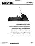
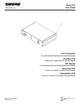
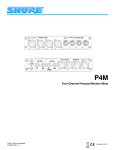
1
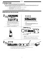
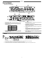
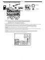
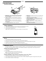
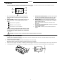
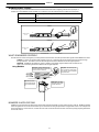
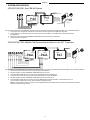
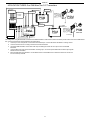
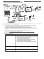
Model PSM 400 Wireless Personal Performance Pack User Guide PSM 400 Wireless Personal Performance Pack Featuring the P4M Mixer, P4T Transmitter and P4R Receiver Ensemble personnel pour concert PSM 400 Comprend le mélangeur P4M, l’émetteur P4T et le récepteur P4R PSM 400 individuelles Monitorsystem Bestehend aus dem P4M–Mischer, P4T–Sender und P4R–Empfänger Sistema personal PSM 400 Incluye una mezcladora P4M, un transmisor P4T y un receptor P4R Sistema completo per uso individuale PSM 400 Comprende il mixer P4M, il trasmettitore P4T e il ricevitore P4R © 2010 Shure Incorporated 27D8706 (Rev. 7) Patent Des. 442,938 Printed in U.S.A. ENGLISH WARNING! USING THIS SYSTEM AT EXCESSIVE VOLUMES CAN CAUSE PERMANENT HEARING DAMAGE. USE AS LOW A VOLUME AS POSSIBLE. In order to use this system safely, avoid prolonged listening at excessive sound pressure levels. Please use the following guidelines established by the Occupational Safety Health Administration (OSHA) on maximum time exposure to sound pressure levels before hearing damage occurs. 90 dB SPL at 8 hours 95 dB SPL at 4 hours 100 dB SPL at 2 hours 105 dB SPL at 1 hour 110 dB SPL at 1/2 hour 115 dB SPL at 15 minutes 120 dB SPL — avoid or damage may occur It is difficult to measure the exact Sound Pressure Levels (SPL) present at the eardrum in live applications. In addition to the volume setting on the PSM, the SPL in the ear is affected by ambient sound from floor wedges or other devices. The isolation provided by the fit of quality earphones is also an important factor in determining the SPL in the ear. Here are some general tips to follow in the use of this product to protect your ears from damage: 1. Turn up the volume control only far enough to hear properly. 2. Ringing in the ears may indicate that the gain levels are too high. Try lowering the gain levels. 3. Have your ears checked by an audiologist on a regular basis. If you experience wax buildup in your ears, stop using the system until an audiologist has examined your ears. 4. Wipe the earphones with an antiseptic before and after use to avoid infections. Stop using the earphones if they are causing great discomfort or infection. This symbol indicates that there are important operating and maintenance instructions in the literature accompanying this unit. Licensing Information Changes or modifications not expressly approved by Shure Incorporated could void your authority to operate the equipment. Licensing of Shure wireless microphone equipment is the user’s responsibility, and licensability depends on the user’s classification and application, and on the selected frequency. Shure strongly urges the user to contact the appropriate telecommunications authority concerning proper licensing, and before choosing and ordering frequencies. THIS RADIO EQUIPMENT IS INTENDED FOR USE IN MUSICAL PROFESSIONAL ENTERTAINMENT AND SIMILAR APPLICATIONS. NOTE: THIS EQUIPMENT MAY BE CAPABLE OF OPERATING ON SOME FREQUENCIES NOT AUTHORIZED IN YOUR REGION. PLEASE CONTACT YOUR NATIONAL AUTHORITY TO OBTAIN INFORMATION ON AUTHORIZED FREQUENCIES FOR WIRELESS MICROPHONE PRODUCTS IN YOUR REGION Licensing: Note that a ministerial license to operate this equipment may be required in certain areas. Consult your national authority for possible requirements. Shure Transmitter Model P4T may be used in the countries and frequency ranges listed in Table 1 on page 83. 3 ENGLISH TABLE OF CONTENTS INTRODUCTION . . . . . . . . . . . . . . . . . . . . . . . . . . . . . . . . . . . . . . . . . . . . . . . . . . . . . . . . . . . . . . . . . . . . . . . . . . . . . . . . . 5 PSMR 400 QUICK SET UP GUIDE . . . . . . . . . . . . . . . . . . . . . . . . . . . . . . . . . . . . . . . . . . . . . . . . . . . . . . . . . . . . . . . . . 5 P4M MIXER . . . . . . . . . . . . . . . . . . . . . . . . . . . . . . . . . . . . . . . . . . . . . . . . . . . . . . . . . . . . . . . . . . . . . . . . . . . . . . . . . . . . . 6 Controls and Features . . . . . . . . . . . . . . . . . . . . . . . . . . . . . . . . . . . . . . . . . . . . . . . . . . . . . . . . . . . . . . . . . . . . . . . . 6 Set-Up . . . . . . . . . . . . . . . . . . . . . . . . . . . . . . . . . . . . . . . . . . . . . . . . . . . . . . . . . . . . . . . . . . . . . . . . . . . . . . . . . . . . . . 6 Using the P4M Personal Monitor Mixer . . . . . . . . . . . . . . . . . . . . . . . . . . . . . . . . . . . . . . . . . . . . . . . . . . . . . . . . . . 7 P4T TRANSMITTER . . . . . . . . . . . . . . . . . . . . . . . . . . . . . . . . . . . . . . . . . . . . . . . . . . . . . . . . . . . . . . . . . . . . . . . . . . . . . . 8 Controls and Features . . . . . . . . . . . . . . . . . . . . . . . . . . . . . . . . . . . . . . . . . . . . . . . . . . . . . . . . . . . . . . . . . . . . . . . . 8 Set-Up . . . . . . . . . . . . . . . . . . . . . . . . . . . . . . . . . . . . . . . . . . . . . . . . . . . . . . . . . . . . . . . . . . . . . . . . . . . . . . . . . . . . . . 8 Loop Applications . . . . . . . . . . . . . . . . . . . . . . . . . . . . . . . . . . . . . . . . . . . . . . . . . . . . . . . . . . . . . . . . . . . . . . . . . . . . 9 P4R RECEIVER . . . . . . . . . . . . . . . . . . . . . . . . . . . . . . . . . . . . . . . . . . . . . . . . . . . . . . . . . . . . . . . . . . . . . . . . . . . . . . . . . 10 Controls and Features . . . . . . . . . . . . . . . . . . . . . . . . . . . . . . . . . . . . . . . . . . . . . . . . . . . . . . . . . . . . . . . . . . . . . . . 10 Battery Installation . . . . . . . . . . . . . . . . . . . . . . . . . . . . . . . . . . . . . . . . . . . . . . . . . . . . . . . . . . . . . . . . . . . . . . . . . . . 10 Set-Up . . . . . . . . . . . . . . . . . . . . . . . . . . . . . . . . . . . . . . . . . . . . . . . . . . . . . . . . . . . . . . . . . . . . . . . . . . . . . . . . . . . . . 10 Pushbutton Controls . . . . . . . . . . . . . . . . . . . . . . . . . . . . . . . . . . . . . . . . . . . . . . . . . . . . . . . . . . . . . . . . . . . . . . . . . 10 LCD Screen . . . . . . . . . . . . . . . . . . . . . . . . . . . . . . . . . . . . . . . . . . . . . . . . . . . . . . . . . . . . . . . . . . . . . . . . . . . . . . . . 11 Locking Out the LCD Screen . . . . . . . . . . . . . . . . . . . . . . . . . . . . . . . . . . . . . . . . . . . . . . . . . . . . . . . . . . . . . . . . . . 11 MIXMODER/STEREO CONTROL . . . . . . . . . . . . . . . . . . . . . . . . . . . . . . . . . . . . . . . . . . . . . . . . . . . . . . . . . . . . . . . . . 12 SYSTEM APPLICATIONS . . . . . . . . . . . . . . . . . . . . . . . . . . . . . . . . . . . . . . . . . . . . . . . . . . . . . . . . . . . . . . . . . . . . . . . . 13 TROUBLESHOOTING . . . . . . . . . . . . . . . . . . . . . . . . . . . . . . . . . . . . . . . . . . . . . . . . . . . . . . . . . . . . . . . . . . . . . . . . . . . 15 SPECIFICATIONS . . . . . . . . . . . . . . . . . . . . . . . . . . . . . . . . . . . . . . . . . . . . . . . . . . . . . . . . . . . . . . . . . . . . . . . . . . . . . . . 16 RACK MOUNTING . . . . . . . . . . . . . . . . . . . . . . . . . . . . . . . . . . . . . . . . . . . . . . . . . . . . . . . . . . . . . . . . . . . . . . . . . . . . . . 18 4 ENGLISH INTRODUCTION The PSMR 400 Wireless Personal Performance Pack Thank you for buying the Shure PSM 400 Wireless Personal Performance Pack, featuring the P4M Personal Monitor Mixer, the P4T Transmitter, the P4R Receiver and earphones. Like all Shure PSM personal monitoring products, the PSM 400 provides the many advantages of a wireless, in-ear monitoring system, including: S Improved Sound Quality – high fidelity without the risk of feedback, S S Increased Mobility – your mix moves with you, Personal Control – through volume adjustment and MixModeR. For information on this and other Shure products, visit www.shure.com on the World Wide Web. PSM 400 Quick Set-Up Guide 1. Plug in the PS41 power supply and connect it to mixer’s DC IN connector. Connect mixer’s DC OUT connector to transmitter’s DC input. 2. Attach the antenna to the ANTENNA OUT BNC connector. 3. Connect mixer’s 1/L and 2/R MIX OUT jacks to transmitter’s 1/L and 2/R INPUT jacks. 4. Connect audio sources to mixer’s MIC/LINE INPUTS. 5. Mix audio sources using LEVEL/PAN knobs. Use outer ring to pan signal left or right, and use inner knob to adjust signal level. 6. Check signal/clip LEDs. FREQ MIX EQ LIM 7. Insert battery into receiver. 8. Turn receiver volume knob past click (ON). Keep volume at minimum. 9. Set receiver functions (see P4R Receiver on page 10). 10. Set transmitter and receiver to same frequency channel. 11. Check RF symbol on receiver LCD to confirm RF reception. 12. Insert earphones into earphone jack on the receiver. Insert earphones into your ears. 13. Slowly increase receiver volume to a comfortable level. 5 ENGLISH THE P4M MIXER Controls and Features 2 1 MIXER FRONT PANEL 4 3 5 6 7 MIXER BACK PANEL 1. 2. MIC/LINE INPUT Jacks: Accommodate both XLR and 1/4” connectors at mic or line levels. They are electronically balanced. Signal/Clip LEDs: Color indicates the signal status of the corresponding mic/line input: LED Color 3. Signal Status Green Signal present Yellow Nominal Level Red Signal clipping CONCENTRIC LEVEL/PAN Knobs: The inner knob controls the input level; the outer ring pans the input signal between the 1/L and 2/R mix outputs. 8 4. MIX OUT Output Jacks: 1/4” TRS jacks provide the line level mix created with the level/pan knobs. 5. AUX IN Inputs: Signals from two 1/4” TRS input jacks are combined with the mix created by the level/pan knobs. Front panel settings do not affect these jacks. 6. DC IN Locking Connector: Plug the PS41 AC adaptor into this connector. 7. DC OUT Locking Connector: Powers a P4T transmitter or another P4M mixer. A DC jumper cable is provided with the mixer. NOTE: A PS41 can only power two Shure devices. 8. SPLIT OUTPUTS: Each male XLR output provides a duplicate of its corresponding mic/line input. Front panel settings have no effect on split outputs. Set-Up Mixer Back Panel PS41 AC Adaptor 1. 2. 3. Audio Sources Mixer Front Panel To audio input of transmitter Plug the PS41 AC adaptor into the mixer’s DC IN locking connector. Plug the other end into a wall socket. Connect the MIX OUT jacks to the audio input of the P4T wireless transmitter. Connect up to four audio sources (microphones, instruments, mixers) into the input jacks on the front panel of the mixer. 6 ENGLISH Using the P4M Personal Monitor Mixer Pans between Mix Out channels DIRECT BOX AUDIO INPUT 1 AUDIO INPUT 2 AUDIO INPUT 3 1/L Adjust levels to Mix Outs (–) MIX OUT 2 MIX OUT 1 SPLIT OUTPUT 4 2. 3. 4. (+) SPLIT OUTPUT 1 SPLIT OUTPUT 3 AUX IN 1/L AUX IN 2/R 1. 2/R AUDIO INPUT 4 SPLIT OUTPUT 2 Once the basic set up is complete, use the P4M Personal Monitor Mixer to create a custom mix: Mix the signal from each audio input using the corresponding CONCENTRIC LEVEL/PAN knob: OUTER RING: Use this to pan the signal to the left or right channel of the stereo mix. INNER KNOB: Use this to control the level of the audio input. Observe the signal/clip LEDs next to each CONCENTRIC LEVEL/PAN knob. NOTE: Decrease the level of an input if the corresponding signal/clip LED is consistently red. If the level is decreased all the way and the LED remains red, the level of the input from the previous device in the audio chain is too high and should be decreased. Up to two additional line-level audio sources (such as other mixers, a click track or a digital sequencer) may be added via the AUX IN inputs. These signals go directly to the MIX OUT outputs and are not affected by the CONCENTRIC LEVEL/ PAN knobs. To pass an unaltered signal through the mixer, use the corresponding SPLIT OUTPUT. NOTE: Although the mixer does not provide phantom power for condenser microphones, the SPLIT OUTPUTS can pass phantom power from a phantom power supply to a microphone connected to the corresponding input jack. CAUTION!: Use a “direct box” when connecting guitars, keyboards, and other instruments to a mixing console through the P4M Mixer. The phantom power that mixing consoles provide for microphones can damage other instruments. Connect the instrument to the direct box then connect the direct box to the P4M Mixer input. AUX IN 2/R AUX IN 1/L MIX OUT 2/R SUM SPLIT OUTS LEV PAN LEV PAN LEV PAN LEV PAN MIC/LINE INPUTS Audio signal path for the P4M Mixer 7 MIX OUT 1/L SUM ENGLISH THE P4T TRANSMITTER Controls and Features 1 4 3 2 5 TRANSMITTER FRONT PANEL PA715 ANTENNA 7 6 8 9 TRANSMITTER BACK PANEL 1. Local Earphone Output Jack (1/8 inch): Connects to earphones. 4. Transmission Frequency LED: This indicates which of the 16 Channels (0–9 or A–F) is transmitting. 2. Local Earphone Level Control: Adjusts the volume of the local earphone jack’s amplifier. Always listen at low levels. 5. Frequency Select Button: This recessed button changes the transmission channel. (Use a 1/4” plug to press this button.) 3. Input Level LEDs: Two vertical strings of four LEDs display the input level of the left and right input channels. The four LEDs on the left display the status of the signal from channel 1 and the four LEDs on the right display the status of the signal from channel 2: 6. Antenna Connector 50 W, BNC type: This connects to the antenna to transmit UHF signals to the receiver. 7. LOOP OUT Jacks: Two 1/4” TRS jacks allow the audio signal to pass through the transmitter to other devices, including other transmitters, tape recorders, or amplifiers. See LOOP Applications on page 9. 8. Input Jacks: Two 1/4” TRS switching jacks are line level audio inputs. 9. DC Input Connector: Input for PS41 power supply or P4M mixer’s DC jumper cable. LED Signal Status RED (top) Limiter Active YELLOW (middle) Nominal Level GREEN (bottom two) Signal Present Set-Up Follow these directions to set up the P4T transmitter for operation: 1. Plug the mixer’s DC OUT jumper cable into the transmitter’s DC input. 2. Attach the antenna to the ANTENNA OUT BNC connector. 3. Connect the mixer’s MIX OUT 1/L and MIX OUT 2/R to inputs 1/L and 2/R of the transmitter. 4. Select an operating frequency using the FREQUENCY SELECT button. Push the button repeatedly until the LED displays the desired channel. The display will flash. Push and hold the button until the flashing stops to confirm the change (use a 1/4” plug to press the button). 5. 6. IMPORTANT: Never set more than ONE transmitter to the same operating frequency. Once the transmitter transmits audio, observe the INPUT LEVEL LEDs. If the LEDs consistently illuminate red, decrease the output level of the audio source until the red LEDs only flicker occasionally. Set up the P4R receiver as directed in the P4R section of this user’s guide. Make sure that the frequency selected on the receiver matches the frequency selected on the transmitter. 8 ENGLISH Loop Applications The LOOP OUT 1/L and 2/R outputs allow the signal going through the P4T transmitter to be routed to other devices. The LOOP feature of the transmitter can be used for any number of applications. Shown here are only a few examples of how it can be used. Also see System Application #3. ÑÑÑ ÑÑÑ ÑÑ ÑÑÑÑ P4T TRANSMITTER (BACK PANEL) ÑÑÑ ÑÑ Ñ ÑÑ ÑÑ P4R Receiver Floor Monitor Amplifier Running Floor Monitors Through a P4T Transmitter: An audio signal can be sent through the LOOP connectors to an amplifier for an onstage monitor system. When setup this way, the P4R and the onstage monitors will reproduce the same audio. BAND MIX SOLO MIX 1 SOLO MIX 2 SOLO MIX 1 ÑÑÑÑ AUX 1 AUX 2 AUX 3 BAND MIX BAND MIX P4T TRANSMITTER AUX 4 P4R RECEIVER MIXING CONSOLE SOLO MIX 2 BAND MIX P4T TRANSMITTER BAND MIX P4R RECEIVER SOLO MIX 3 SOLO MIX 3 BAND MIX P4T TRANSMITTER P4R RECEIVER Running Multiple PSM Wireless Systems Under MixMode Control: When using a mixer with multiple auxiliary out jacks, a single monitor mix can be sent to multiple P4T transmitters using the LOOP connectors, and independent monitor mixes or direct outputs can be sent directly to the second channel of each P4T. This allows each P4T user to mix a band mix signal with a solo mix signal using the MixMode feature on the receiver. The thumbwheel on the P4R is used to mix the two signals in relation to one another. ÑÑ Ñ Ñ Ñ Ñ ÑÑÑÑÑ Ñ Ñ Running a Recording Device Through a P4T Transmitter: If you would like to make a recording of a performance, the LOOP outputs can be connected to the inputs of a tape deck, DAT, or other recording device. 9 ENGLISH P4R RECEIVER Controls and Features 9 1 7 P4R TOP PANEL 8 FREQ MIX EQ LIM 4 2 3 1. Balance Knob: This thumbwheel adjusts the left/right balance when the unit is in stereo and the Mix 1/Mix 2 balance when the unit is in MixMode. 2. SCROLL Pushbutton: Use with the SELECT pushbutton to control the functions in the LCD screen. See Pushbutton Controls on page 10. 3. SELECT Pushbutton: Use with the SCROLL pushbutton to control the functions in the LCD screen. See Pushbutton Controls on page 10. 4. 1/8” Earphone Output Jack: Connects to earphones. 5. 6. 7. 8. 9. 6 5 Belt Clip: Securely attaches the receiver to a belt, guitar strap or waist band. LCD Screen: The LCD Screen displays the status of various functions. See LCD Screen on page 11. ON/OFF/VOLUME Knob: Turn clockwise past click to turn ON. Continue to turn clockwise to increase volume, counterclockwise to decrease volume. Battery Compartment Door: See Battery Installation on page 10. Antenna: An attached, flexible whip antenna receives radio frequency (RF) from the Transmitter. Battery Installation 1. Open the battery compartment door by pushing down and sliding towards the antenna. 2. Insert a fresh 9V alkaline battery with the +/– terminals properly positioned. 3. Close the battery compartment door. Note: If battery compartment door will not close, the battery is not properly inserted. Set-up 1. Turn the ON/OFF/VOLUME knob clockwise past click (ON). 2. Check the LCD Screen to see if RF is being received. (see LCD Screen on page 11). 3. Plug earphones into earphone output jack. Insert earphones into ears as instructed in the earphone user’s guide. 4. Increase the volume slowly until a comfortable listening level is achieved. 5. Set the desired functions in the LCD screen as described in LCD Screen on page 11. Pushbutton Controls Push either the SCROLL or SELECT pushbutton to activate the LCD Screen. Push and hold the SCROLL pushbutton to scroll through the functions. The current function is underscored. Use the SELECT pushbutton to change the status of the underscored function. Changing the Reception Channnels 1. Push and hold the SCROLL pushbutton. 2. Scroll to FREQ. 3. Push the SELECT pushbutton to select a channel (0–9 or A–F). 4. Push the SCROLL pushbutton to confirm changes. NOTE: Use the same reception channel as the P4T transmitter. Changing MixMode, High Frequency Equalization and Limiter Status 1. Push and hold the SCROLL pushbutton. Scroll to the desired function (MIX, EQ, or LIM). 2. Push the SELECT pushbutton to toggle the function ON or OFF. A function is ON when a dot appears to the right of the function symbol. 3. Push the SCROLL pushbutton to confirm changes. 10 ENGLISH LCD Screen The LCD Screen on the top panel displays the status of various functions. The status of these functions can be changed using the SCROLL and SELECT pushbuttons (see Pushbutton Controls on page 10). 4 1 FREQ MIX EQ 5 LIM 2 6 3 1. 2. 3. RF: Indicates the P4R receiver is receiving a transmission. Always check for RF reception prior to inserting earphones into ears. Battery Life Meter: Indicates the approximate amount of voltage left in the battery. These voltages translate to time as follows: 4. HIGH: 4-8 hours of operation. MEDIUM: 1-4 hours of operation. 5. LOW: less than 1 hours of operation. 6. NOTE: If no bars are present within the battery life gauge, change the battery immediately. Battery life depends on many variables, including battery type (brand), earphones used, and receiver volume setting. RECEPTION CHANNEL (FREQ): The P4R receiver features 16 preset, user-selectable channels (0–9 and A–F). The receiver must be set to the same channel as its transmitter. MixMode (MIX): The receiver receives the monitor mix in either MixMode (MIX ON) or stereo (MIX OFF). See MixMode/ Stereo Control on page 12. NOTE: If the receiver is receiving only one signal, it will be in mono. High Frequency Equalization (EQ): Adds 6 dB at 10 KHZ for increased treble response. Limiter (LIM): The limiter provides protection against loud signals. WARNING! Turning the Limiter OFF defeats protection against hazardous sound levels! Locking Out the LCD Screen 1. 2. 3. 4. Once the receiver’s functions are set for use, lock out the LCD screen and pushbuttons to prevent unwanted changes during or between performances. To lock out the front panel: Set all functions to desired settings. Hold down the SCROLL and SELECT pushbuttons simultaneously for five seconds (A). NOTE: The reception channel will be replaced by dashes (B) when lock-out is engaged. When lock-out is engaged, the SCROLL and SELECT pushbuttons light the LCD screen, but cannot change the status of any of the functions. To disengage the lock-out, hold the SCROLL and SELECT pushbuttons for five seconds until the reception channel is displayed again. FREQ MIX EQ LIM A B 11 ENGLISH MixMode/Stereo Control The flexible design of the PSM 400 Wireless Personal Performance Pack makes configuring a monitor mix very simple. In addition, the unique MixMode circuitry enables you to customize your own individual mix in a multiple mix environment. Used for mixing and combining an individual mix between two distinct monitor sends. MixMode Control Stereo Control Used for conventional stereo monitor mixes. Mono Control Used when only one (mono) monitor mix is available. STEREO 1/L 1/L Signal from Audio Source 2/R 2/R MIXMODE 1/L and 2/R 1/L Signal from Audio Source MIXED 2/R P4R RECEIVER P4T TRANSMITTER WHAT IS MIXMODE CONTROL? The P4R receiver receives two signals (1/L and 2/R) from the P4T transmitter. The P4R processes these signals in either MixMode or stereo: STEREO: In stereo, the signals remain separate so that 1/L is heard through the left earphone and 2/R is heard through the right earphone. The balance knob on the P4R adjusts the balance between the left and right earphones. MIXMODE: In MixMode, the signals are “mixed” in relation to one another using the balance knob, blended into one signal. The one mixed signal is sent to both the left and right earphones. Using MixMode Step Two: Using the balance knob, the user blends the two signals until the correct mix is achieved. MIXMODE channel 1 COUNTERCLOCKWISE MID-POINT Step Four: The user may continue to adjust the blend using the balance knob throughout the performance. MIXMODE channel 2 CLOCKWISE Step One: The P4R receives TWO signals from the P4T transmitter. Step Three: The P4R sends the mixed signal to both earphones. MIXMODE IN APPLICATIONS MixMode is most useful when two distinct mixes are provided to the P4T transmitter, such as a band mix and a vocal mix. MixMode combines these two signals into one monitor mix and allows you to control this mix during the performance using the P4R receiver. For example, if the band overpowers the vocals in the mix, increase the level of the vocals and decrease the level of the band by simply adjusting the balance knob on the receiver. 12 ENGLISH SYSTEM APPLICATIONS APPLICATION ONE: One PSM 400 System RF TRANSMISSIONS MIX OUTPUTS P4M Personal Monitor Mixer LINE INPUTS P4T P4R Transmitter INPUTS 1–4 Receiver RF RECEPTION LEVEL/PAN KNOBS 1–4 This is the basic configuration of the PSM 400 system and is the recommended configuration for small ensembles in live or rehearsal situations. 1. Connect up to four microphones, instruments or audio devices to the four inputs on the P4M mixer front panel. 2. Connect MIX OUT 1/L and MIX OUT 2/R on the back panel of mixer to INPUT 1/L and INPUT 2/R on the back panel of the P4T transmitter. 3. Mix the four signals using the CONCENTRIC LEVEL/PAN knobs on the front panel of the mixer. 4. Transmit the mix to the receiver. APPLICATION TWO: Multiple P4M Personal Monitor Mixers to One P4T Transmitter MIX OUTPUTS P4M Personal Monitor Mixer INPUTS 1–4 AUX INPUTS P4M Personal Monitor Mixer INPUTS 1–4 LINE INPUTS P4T Transmitter LEVEL/PAN KNOBS 1–4 This application, using the P4M’s AUX inputs, allows more than four inputs to be mixed. Recommended for large ensembles in live or rehearsal situations. 1. Connect up to four audio sources to the front panel inputs of the P4M mixer. 2. Mix these signals using the CONCENTRIC LEVEL/PAN knobs on the mixer. 3. Connect the MIX OUTPUTS of the first mixer to the AUX INPUTS of a second P4M mixer. 4. Connect up to four more audio sources into the front panel inputs of the second P4M Mixer. 5. Mix these signals using the CONCENTRIC LEVEL/PAN knobs on the second mixer. 6. Connect the MIX OUTPUTS of the second mixer to the LINE INPUTS of the P4T transmitter. The transmitter receives a mix consisting of all eight audio sources, which it transmits to the P4R receiver. NOTE: If more than eight inputs are required, connect additional P4M mixers between the second mixer and the transmitter using the connection described in step 3 above. 13 ENGLISH APPLICATION THREE: One P4M Mixer/Two P4T Transmitters Monitor Mix Other Audio Sources Mix 2/R To Mixing Console Line Inputs LOOP Outputs PSM PSM Mixing Console RECEIVER Transmitter Mix 1/L Split Outputs RF Transmission Mix Outputs Line Inputs P4M Inputs 1–4 Monitor Mix PSM PSM Personal Monitor Mixer Transmitter RECEIVER RF Reception Level/Pan Knobs 1–4 This configuration, using the P4M’s SPLIT OUTPUT and a PSM transmitter’s LOOP OUTPUT, allows one P4M to provide custom mixes to two PSM transmitters, and is recommended for small ensembles in live performance: 1. 2. 3. 4. 5. Connect up to four microphones or instruments into the P4M inputs. Connect the SPLIT OUTPUTS to a mixing console. Connect a monitor mix from a mixing console to the first P4T transmitter. On the first PSM transmitter, connect the LOOP output containing the monitor mix to an input on the second PSM transmitter. Connect a MIX OUT output to each transmitters’ remaining input. Use the front-panel PAN knobs to balance input signals between the two transmitters. Place the PSM receivers in MixMode. Use the balance wheel on the PSM receiver to blend the monitor mix with the custom mix created by the P4M. 14 ENGLISH APPLICATION FOUR: Multiple PSM 400 Systems Other Audio Sources To Next P4M or Amplifier To Mixing Console INPUTS To Mixing Console P4M INPUTS Mixing Console Personal Monitor Mixer Line Inputs P4T P4R Transmitter Receiver Shared Mic/Line Signal Monitor Mix RF Transmission Split Outputs 1-4 Mix Outputs P4M Line Inputs P4T Personal Monitor Mixer P4R Transmitter Inputs 1–4 Receiver RF Reception Level/Pan Knobs 1–4 Monitor Mix This configuration uses the P4M’s SPLIT OUTPUTS to pass audio signal to other P4M Personal Monitor Mixers. Each player can create a custom mix at their mixer. Recommended for live, studio or rehearsal situations. 1. Connect a monitor mix signal (from a mixing console) and up to three audio sources to the four inputs on the mixer’s front panel. 2. Connect the SPLIT OUTPUT of the mixer containing the monitor mix to an input on a second mixer. 3. Connect the other SPLIT OUTPUTS from the first mixer to either the second mixer or to the mixing console. 4. On the second mixer, connect the SPLIT OUTPUT containing the monitor mix to a third mixer or to a floor monitor amplifier. 5. Connect MIX OUT 1/L and MIX OUT 2/R on the back panel of each mixer to INPUTS 1/L and 2/R on the back panel of a P4T transmitter. 6. On each mixer, mix the four signals using the CONCENTRIC LEVEL/PAN knobs on the front panel. 7. Transmit the mix from each transmitter to its respective P4R receiver. TROUBLESHOOTING PROBLEM SOLUTION No sound at the receiver n Check the power cord on the transmitter and make sure it is powered on. n Make sure both the transmitter and the receiver are set to the same frequency. n Make sure the earphones are plugged in to the receiver. n Make sure receiver is on and the battery is good. n Listen to the headphone monitor on the transmitter to check audio feed. n Make sure the antenna is connected to the transmitter. n Check the incoming audio and power connections and the outgoing audio connections at the mixer. n Try to maintain line-of-sight between transmitter and receiver. n Try another frequency in case interference is limiting the range. n Check for television channel interference. n Make sure no other transmitters are operating on your frequency. n Make sure transmitter input level is lighting yellow LEDs for optimum performance. n Listen to the headphone monitor on the transmitter to check audio feed. n Make sure transmitter input level is lighting yellow LEDs for optimum performance. n Make sure the P4R receiver’s volume knob is up. Low receiver range Receiver sounds fuzzy or distorted Low audio output at the receiver 15 ENGLISH SPECIFICATIONS System Specifications RF Carrier Frequency Range 722 to 952 MHz (country dependent) Total Harmonic Distortion (1 KHz) 0.8% typical (Ref. ±35 KHz deviation) Modulation FM ±35 KHz Deviation (Nominal), MPX Stereo Channel Separation 35 dB typical Signal-to-Noise Ratio 80 dB typical (A-weighted) Operating Temperature -7° C to +49° C (+20° F to 120° F) Operating Range 300 ft. (environment dependent) Audio Frequency Response 50 Hz to 12 kHz (+/–3 dB); earphone dependent Image Rejection 55 dB typical Spurious Rejection 60 dB typical P4M Mixer Specifications Measurement Conditions (unless otherwise specified): full gain; 1 KHz, one channel activated; source impedances: Mic 150 Ω, Aux Level 150 Ω; terminations: Line 600 Ω. Frequency Response (Ref 1 KHz, controls centered) 20 Hz to 20 Khz ± 2 dB LEDs: Resultant Mix Out Level Green: -30 dBV Yellow: -10 dBV Red: 0dBV Current 120 mA max. Power Requirements Operating voltage 14–18 Vdc Supplied with one of the following external power supplies: S Model PS41: 120 Vac, 60 Hz input. INPUT Specifications Input 1–4 (front panel) Aux In Gain (Maximum) 43 dB 0 dB Impedance (at 1kHz) 5800 Ω 18 kΩ (each) 9100 Ω (1/L mono) Input Clipping Level +12dBV +12 dBV Crosstalk -100 dB -90 dB Common Mode Rejection > 75 dB > 70 dB S Model PS41E, Model PS41UK: 230 Vac, 50/60 Hz input. NOTE: Courtesy DC connector is protected from short by a self-resetting “Polyfuse”. Maximum recommended load is 250mA (2 P4Ms or 1 P4T.) Phantom Power The P4M does not produce phantom power, but phantom power is allowed to pass through Split Outputs 1–4 to inputs 1–4 respectively. Audio Polarity All outputs in polarity with all inputs. XLR Pin 2 is “hot” with respect to Pin 3; Pin 1 is ground. 1/4” TRS tip is “hot” with respect to ring; sleeve is ground. Temperature Range Operating . . . . . . . . . . . . . . . . . . . . . . . . . -7° to 49° C (20° to 120° F) Storage . . . . . . . . . . . . . . . . . . . . . . . . . . -29° to 74° C (-20° to 165° F) Overall Dimensions 44 mm H x 218 mm W x 162 mm D (1.72 x 8.60 x 6.37 inches) Net Weight 1.20 Kg (2 lbs, 10 oz) OUTPUT Specifications Output Split 1 – 4 Mix Out Impedance N/A 500 Ω Output Clipping Level N/A +5 dBV (10 kΩ balanced load, -30 dBV input ch. 1 – 4.) Noise (100 Hz to 22 kHz) -110 dBV -100 dBV (all controls CCW) -62 dBV (all controls CW) Distortion (THD) at 1kHz) .0005% < .05% (0 dBV output) Crosstalk -100 dB -70 dB P4T Transmitter Specifications Current 250 mA maximum RF Output Power 50 mW (+17 dBm) typical conducted (country dependent) Modulation Limiter Internal peak limiter (>10:1 compression) Antenna External whip, 50 Ω BNC connector Dimensions 219.2 mm X 43.6 mm X 136.5 mm (8.6 in. X 1.7 in. X 5.4 in.) Net Weight 907.2 g (2 lbs., 0 oz.) 16 ENGLISH CONNECTORS P4T Audio Inputs (1/L and 2/R) Connector Type: Configuration: 1/ -inch 4 P4T L/R LOOP Outputs (1/L and 2/R) jack (female) TRS 1/ -inch 4 Connector Type: electronically balanced jack (female) TRS Configuration: electronically balanced Actual Impedance: 20 k� -10 dBV/-7.8 dBu Actual Impedance: 20 k� Nominal Input Level: +15 dBu Nominal Output Level: -10 dBV/-7.8 dBu Maximum Input Level: Tip = hot ring = cold sleeve = ground Maximum Output Level: +15 dBu Pin Assignments: Pin Assignments: Phantom Power Protection? Yes Up to 50 VDC Tip = hot ring = cold sleeve = ground Phantom Power Protection? Yes Up to 50 VDC Power Requirements Operating voltage 14–18 Vdc Supplied with one of the following external power supplies: Model PS4: 120 Vac, 60 Hz input. Model PS4E, Model PS4UK: 230 Vac, 50/60 Hz input. P4R Receiver Specifications RF Sensitivity 1 µV typical Image Rejection 55 dB typical Spurious Rejection 60 dB typical Squelch Threshold 4.5 µV typical Antenna Attached Whip Power Requirements 9 V alkaline battery Battery Life Up to 8 hours, volume dependent Audio Output Connector 3.5 mm Stereo (Left = tip, Right = ring, Ground = sleeve) Minimum Load Impedance 16 � Net Weight 125 g (.28 lbs.) Overall Dimensions 82.6 mm X 63.5 mm X 26.2 mm (3 1/4 in. X 2 1/2 in. X 1 1/32 in.) Furnished Accessories Optional Accessories PA770 (120VAC): 720 to 750 MHz Antenna Combiner . . . . . . . . . . . . . . . . . . . . . . . . PA770E (240 VAC): 720 to 750 MHz Unidirectional Antenna . . . . . . . . . . . . . . . . . . . . . . . .. . . . . . PA705 10 ft Coaxial Antenna Cable (BNC connector) . .. . . .. . . . . . .. . PA725 Transmitter Antenna UA400: 774-952 MHz Transmitter Antenna PA715: 524-715 MHz . . . . . . . . . . . . . . . . . . . . . . . . . . .. . . . . . . . . . . . Dual Mount Rack Bracket 53B8484 Straddle Bars . . . . . . . . . . . . . . . . . . . . . . . . . . . . . . . .. 53A8443 AC Adaptor . . . .. . . . PS4 (120V), PS4E (230V), PS4UK (230V) DC Jumper Cable . . . . . . . . . . . . . . . . . . . . . . . . . . . . . . . . 95A8420 Certifications P4M: Eligible to bear mark. Conforms to European Union EMC directive 89/336/EEC. Meets applicable tests and performance criteria in European EMC Standard EN 55103 (1996) parts 1 and 2, for residential (E1) and light industirial (E2) environments. P4T: Type Accepted under Part 74, FCC ID DD4P4TA. Certified by IC in Canada under RSS–123. EP4T: Meets the essential requirements of European R&TTE DirecO682 tive 99/5/EC, eligible to bear CE mark: . Type approved to EN 300 422 Parts 1 and 2. Meets requirements of EMC Standard EN 301 489. P4R: Approved under the DECLARATION OF CONFORMITY provision of FCC Part 15. Certified in Canada by IC under RSS-123. Meets essential requirements of European Union R&TTE Directive 99/5/EC, eligible to bear mark. Meets requirements of EMC standards EN 300 422 Parts 1 and 2 and EN 301 489 Parts 1 and 9. PS4: Conforms to applicable U.S. and Canadian electrical and safety standards PS4E/PS4UK: Conforms to European low voltage directive 72/23/EEC. Eligible to bear CE marking: . SHURE P4R Tested To Comply With FCC Standards FOR HOME OR OFFICE USE 17 N 108 ENGLISH RACK MOUNTING OPTIONS Rack Mounting the P4T and P4M Both the P4T and P4M feature a 1/2-rack chassis specially designed for sturdiness. The sagging and bending found in most 1/2-rack designs is eliminated — the brackets and straddle bars are designed to ensure that the units will be installed securely. WARNING: Do not torque the screws too tightly, or the chassis may be damaged. Mounting Units ÑÑÑ ÑÑÑÑÑÑÑÑ ÑÑ ÑÑÑ ÑÑÑÑÑÑÑ ÑÑÑ ÑÑÑ ÑÑ ÑÑ ÑÑ ÑÑÑ ÑÑ Ñ ÑÑ ÑÑÑÑÑ Ñ Ñ ÑÑÑÑÑ ÑÑÑÑÑÑÑ ÑÑÑÑÑ Ñ ÑÑÑ Ñ ÑÑ ÑÑ ÑÑÑÑÑÑÑÑÑÑÑÑ ÑÑ ÑÑÑÑ ÑÑÑÑÑ Ñ NOTE: Be sure to use both straddle bars when installing dual units. Mounting in an Equipment Rack ÑÑÑ ÑÑÑ ÑÑÑÑÑÑÑ Ñ ÑÑÑ ÑÑÑÑÑ ÑÑ ÑÑÑ ÑÑÑ ÑÑÑ ÑÑ ÑÑÑÑÑÑ Ñ Ñ ÑÑÑÑÑÑ Ñ ÑÑÑ ÑÑÑ Ñ ÑÑ ÑÑ ÑÑÑÑÑÑÑ ÑÑ Ñ ÑÑÑÑÑÑÑ ÑÑÑ 18 TABLE 1 TABLEAU 1 TABELLE 1 TABLA 1 TABELLA 1 Country Code Code de Pays Lander–Kurzel Código de país Codice del Paese P4T–HF (722 – 746 MHZ) P4T–P3 (722 – 746 MHZ) P4T–MN (800 – 830 MHZ) P4T–KE (842 – 865 MHZ) A 722 – 746 MHZ * * 800 – 830 MHZ * 842 – 865 MHZ * B 722 – 746 MHZ * * 800 – 830 MHZ * 842 – 865 MHZ * CH 722 – 746 MHZ * * 800 – 830 MHZ * 842 – 865 MHZ * D 722 – 746 MHZ * * 800 – 830 MHZ * 842 – 865 MHZ * E 722 – 746 MHZ * * 800 – 830 MHZ * 842 – 865 MHZ * F * 722 – 746 MHZ * * * GB 722 – 746 MHZ * * * 842 – 865 MHZ * GR 722 – 746 MHZ * * 800 – 830 MHZ * 842 – 865 MHZ * I 722 – 746 MHZ * * * 863 – 865 MHZ* IRL 722 – 746 MHZ * * 800 – 830 MHZ * 842 – 865 MHZ * L 722 – 746 MHZ * * 800 – 830 MHZ * 842 – 865 MHZ * NL 722 – 746 MHZ * * 800 – 830 MHZ * 842 – 865 MHZ * P 722 – 746 MHZ * * 800 – 830 MHZ * 842 – 865 MHZ * DK * * 800 – 820 MHZ * 863 – 865 MHZ* FIN * * 800,1 – 819,9 MHZ * 863 – 865 MHZ* N * * 800 – 820 MHZ * 863 – 865 MHZ* S * * 800 – 814 MHZ * 863 – 865 MHZ* * * * * All Other Countries Tous les autres pays Alle anderen Länder Demás países Tutti gli altri Paesi *Please contact your national authority for information on available legal frequencies for you8r area and legal use of the equipment. *Se mettre en rapport avec les autorités compétentes pour obtenir les informations sur les fréquences autorisées disponibles localement et sur l’utilisation autorisée du matériel. *Für Informationen bezüglich der für Ihr Gebiet verfügbaren gesetzlich zugelassenen Frequenzen und der gesetzlichen Bestimmungen für den Einsatz der Geräte setzen Sie sich bitte mit der zuständigen örtlichen Behörde in Verbindung. * Comuníquese con la autoridad nacional para obtener información en cuanto a las frecuencias legales disponibles y usos legales del equipo en su área. *Rivolgersi alle autorità competenti per ottenere informazioni relative alle frequenze autorizzate nella propria regione e alle norme che regolano l’uso di questo apparecchio. 83 Declaration of Conformity We, of EU DECLARATION OF CONFORMITY We, of Shure Incorporated 5800 W. Touhy Avenue Niles IL 60714–4608 U.S.A. 847–600–2000 Declare under our sole responsibility that the following product Declare under our sole responsibility that the following product, Model: P4R Shure Incorporated 5800 Touhy Avenue Niles, Illinois, 60714-4608 U.S.A. Phone: (847) 600-2000 Web: www.Shure.com Description: Receiver Has been tested and found to comply with the limits for an unintentional radiator device, and approved under the Declaration of Conformity provision of the Part 15 of the FCC rules. Operation is subject to the following two conditions: 1. This device may not cause harmful interference 2. This device must accept any interference received, including interference that may cause undesired operation. Model: P4T Description: Wireless Transmitter conforms to the essential requirements and other relevant previsions of the R&TTE Directive (1999/5/EC). The product complies with the following product family, harmonized or national standards: ETS 300 445 (1997-03) EN 300 422 V1.2.1 (1999-07) The technical documentation is kept at: Shure Incorporated, Corporate Quality Engineering Division SHURE Europe GmbH, EMEA Approval Manufacturer: Shure Incorporated Signed: __________________________________ Date: 01 February 2010 Name and Title: Craig Kozokar, EMC Project Engineer, Corporate Quality Engineering Division European Representative: SHURE Europe GmbH Shure Incorporated., Manufacturer. Signed: November 12th, 2003 Name, Title: Craig Kozokar, EMCProject Engineer, Corporate Quality, Shure Incorporated Signed: __________________________________ Date: 01 February 2010 Name and Title: Wolfgang Bilz, Dipl. Ing. (FH), EMEA Approval SHURE Europe GmbH Headquarters Europe, Middle East & Africa Wannenäcker Str. 28 D-74078 Heilbronn, Germany Phone: +49 - (0)7131 - 7214 - 0 Fax: +49 - (0)7131 - 7214 - 14 Note: This equipment has been tested and found to comply with the limits for a Class B digital device, pursuant to part 15 of FCC Rules. These limits are designed to provide reasonable protection against harmful interference in a residential installation. This equipment generates, uses and can radiate radio frequency energy and, if not installed and used in accordance with the instructions, may cause harmful interference to radio communications. However, there is no guarantee that interference will not occur in a particular installation. If this equipment does cause harmful interference to radio or television reception, which can be determined by turning the equipment off and on, the user is encouraged to try to correct the interference by one or more of the following measures: Reorient or relocate the receiving antenna. Increase the separation between the equipment and the receiver. Connect the equipment into an outlet on a circuit different from that to which the receiver is connected. Consult the dealer or an experienced radio/TV technician for help. SHURE Incorporated http://www.shure.com United States, Canada, Latin America, Caribbean: 5800 W. Touhy Avenue, Niles, IL 60714-4608, U.S.A. Phone: 847-600-2000 U.S. Fax: 847-600-1212 Intl Fax: 847-600-6446 Europe, Middle East, Africa: Shure Europe GmbH, Phone: 49-7131-72140 Fax: 49-7131-721414 Asia, Pacific: Shure Asia Limited, Phone: 852-2893-4290 Fax: 852-2893-4055