1
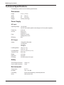
Server Farm Model MA3a User Guide User Guide 88311200, Revision A MultiArrayIII (Model # MA3a) User Configurable Multiple-processor Rack Mount Chassis This publication may not be reproduced, in whole or in part, without prior expressed written permission from Multi-Tech Systems, Inc. All rights reserved. Copyright © 1998, by Multi-Tech Systems, Inc. Multi-Tech Systems, Inc. makes no representations or warranties with respect to the contents hereof and specifically disclaims any implied warranties of merchantability or fitness for any particular purpose. Furthermore, Multi-Tech Systems, Inc. reserves the right to revise this publication and to make changes from time to time in the content hereof without obligation of Multi-Tech Systems, Inc. to notify any person or organization of such revisions or changes. Record of Revisions Revision Description A (12/7/98) Manual Released. All pages at revision A. Patents This Product is covered by one or more of the following U.S. Patent Numbers: 5.301.274; 5.309.562; 5.355.365; 5.355.653; 5.452.289; 5.453.986. Other Patents Pending. Trademarks Multi-Tech, MultiArray, and the Multi-Tech logo are trademarks of Multi-Tech Systems, Inc. Multi-Tech Systems, Inc. 2205 Woodale Drive Mounds View, Minnesota 55112 (612) 785-3500 or (800) 328-9717 Fax (612) 785-9874 Tech Support (800) 972-2439 BBS (612) 785-3702 or (800) 392-2432 Internet Address: http://www.multitech.com Fax-Back (612) 717-5888 Contents Chapter 1 - Introduction and Description Introduction ................................................................................................................................................ Manual Organization .................................................................................................................................. Technical Specifications ............................................................................................................................. Dimensions .......................................................................................................................................... Power Supply ....................................................................................................................................... Safety ................................................................................................................................................... Environmental ...................................................................................................................................... 6 7 8 8 8 8 8 Chapter 2 - Installation Quick Start Unpacking ................................................................................................................................................ 10 Safety Warnings ....................................................................................................................................... 10 Pre-Installation Notes ................................................................................................................................ 11 Configuration Considerations .................................................................................................................... 11 9-Pin DSUB Openings ....................................................................................................................... 12 Backplane Board ............................................................................................................................... 13 Hardware Installation Procedure .............................................................................................................. 14 Installing PC Boards .......................................................................................................................... 14 Internal SBC Cabling ......................................................................................................................... 16 Disk Drive Installation ........................................................................................................................ 18 8-Bay Disk Drive Cabling ................................................................................................................... 20 Installing a Disk Drive into Horizontal Chassis ................................................................................ ... 22 Replacing Cover ....................................................................................................................................... 25 Mounting Optional Rails (MARAIL) .......................................................................................................... 25 External Cabling ....................................................................................................................................... 26 SBC Board Cabling ............................................................................................................................ 26 NIC Cabling ....................................................................................................................................... 26 ISI Board Cabling ............................................................................................................................... 26 Powering Up ............................................................................................................................................. 27 Chapter 3 - Software Loading Introduction .............................................................................................................................................. 30 Configuring Multiple SBCs ....................................................................................................................... 30 Software Documentation .......................................................................................................................... 30 Chapter 4 - Troubleshooting Troubleshooting ........................................................................................................................................ 32 Diagnostic Tests ....................................................................................................................................... 33 Before Calling Technical Support ............................................................................................................. 33 iii Chapter 5 - Warranty, Service and Technical Support Introduction .............................................................................................................................................. Limited Warranty ...................................................................................................................................... On-line Warranty Registration ............................................................................................................ Tech Support ............................................................................................................................................ Recording MultiArray Information ...................................................................................................... Service ..................................................................................................................................................... The Multi-Tech BBS ................................................................................................................................. About CompuServe .................................................................................................................................. About the Internet ..................................................................................................................................... About the Multi-Tech Fax-Back Service ................................................................................................... iv 36 36 36 37 37 38 39 40 40 40 Chapter 1 - Introduction and Description MultiArray User Guide Introduction The MultiArrayIII™ user-configurable multiple-processor server farm (model MA3a) is designed to consolidate up to nine network servers into a single system that can be mounted in a standard 19-inch rack enclosure. The MA3a contains a user-configurable 20-slot segmented backplane that sits on the floor of the chassis. On the upper left front of the chassis sits an 8-bay, 3½" vertical disk drive chassis. A combination 3½" floppy disk drive and 5¼" CD-ROM (both included in the basic chassis) resides on the upper-right front. Dual redundant hot-swappable power supplies make up the bottom of the front side. The configurable backplane allows you to customize for unique applications and third-party components by combining segments. For example, combining the first two segments into a 6-slot arrangement allows for a 32-port asynchronous data/fax communications server. The front of the MA3a is shown in Figure 1-1, below. B 115 115 115 D 115 A I E F H C J F G J Figure 1-1. MultiArrayIII The vertical, 8-bay 3½" disk drive chassis (A) slides out for ease of installing and connecting cables to the hard drives. Each subsegment has its own power switch (B) so that all the components of a subsegment, including disk drives, can be independently powered on or off (these features will be discussed in more detail later in this guide and in the MultiArray User Guide). In addition, the muxing feature provides access to the CD-ROM and floppy drives via the Binary Coded Decimal (BCD) display and muxing switch (C), allowing for smooth software loading on all segments. The horizontal drive chassis (D) contains a 3½" floppy disk drive and a 5¼" CD-ROM. In addition, an open slot allows for the addition of an additional drive, i.e., a ninth hard drive or tape device. The horizontal chassis also slides out for ease of drive installation and cable connections. Individual segments access the CD-ROM and floppy drives via the muxing switch (C), which is set to match the segment number for the appropriate SBC. The power supply chassis located under the drive chassis contains two dual redundant hotswappable power supplies (E). The power supply area is located in the lower portion of the chassis and is accessible from the front of the chassis. Power to the power supplies is controlled by two master power switches (F) which light to indicate power, and each power supply module is controlled by individual power switches (G). Power to each module is indicated by an LED (H) and voltage switches on the individual modules (I) allow for selection of 115V or 230V operation. The alarm reset switch (J) allows the alarm to be reset in the event of a power supply failure. 6 Chapter 1 - Introduction and Description Manual Organization This manual tells you how to install your MultiArray hardware. For information on the Multi-Tech or third party PentiumTM Based Single Board Computer (SBC), Network Interface Card (NIC), Intelligent Serial Interface (ISI) Boards, etc., refer to the user documentation shipped with the board. For information on running software on the MultiArray, refer to the applicable software user documentation, shipped with your software package. The information contained in each chapter is as follows: Chapter 1 - Introduction and Description Chapter 1 begins with an introduction to the MultiArray and continues with a description of its hardware features. The chapter ends with a list of technical specifications. Chapter 2 - Installation Quick Start Chapter 2 provides the PC board and/or disk drive installation procedure, rack mounting procedure, and cable connections for your MultiArray. Chapter 3 - Software Loading Chapter 3 discusses some software options available for the MultiArrayIII. Chapter 4 - Troubleshooting Chapter 4 covers possible steps to take in the event of a MultiArrayIII failure. Chapter 5 - Warranty Service and Tech Support Chapter 5 provides a description of the MultiArray’s two-year warranty, and offers instructions on how to receive service for your MultiArray at the factory. In addition, this chapter provides information about accessing our user bulletin board service (BBS) as well as receiving support via our various Internet resources. 7 MultiArray User Guide Technical Specifications The MultiArrayIII conforms to the following specifications: Dimensions Height: 10.75" (27 cm) Width: 19" (48 cm) Depth: 25" (63.5 cm) Weight: 100 lbs. (45.35 kg) Power Supply AC Input Operating Range: 115-230 VAC 180-270 VAC switch (switch must change on all four power supplies) Frequency: 47-63 Hz Current: 6A @ 115V 3A @ 230 V Fuse: 5A @ 115V, 60 Hz 2.5A @ 230V, 50 Hz Efficiency: 80% DC Output Output: +5V @ 60A (70A peak) +12V @ 28A -5V @ 1A -12V @ 1A Load Regulation: ±5% (+5, +12) ±10% (-5, -12) Line Regulation: ±1% (+5,+12) ±2% (-5,-12) Transient Time: 50ms max Ripple: ±1% (p-p) Hold Time: 16ms min PG Delay: 100-500ms after 5V output Safety Over Voltage Protection: 120% (+5) Over Current Protection: 130% Environmental 8 Temperature: 0-40o C Humidity: 10% - 90% RH Fan Rating: 35cfm (thermostatically controlled) each fan Noise: 30db (A) each fan Chapter 2 - Installation Quick Start MultiArray User Guide Unpacking Check the items on the MultiArray shipping list to ensure that you have received the correct accessories. Your MultiArray should include: • • • • • • • MA3a chassis (with included CD-ROM and floppy drives) Two AC power cords Accessory kit (with jumper cards and ribbon cables) Driver diskette This Quick Start Guide User Guide diskette Tucows® accessory CD Unpack and inspect the MultiArray rack for visible shipping damage. If damage is observed, do not power-on the rack; contact Multi-Tech's Tech Support for advice (refer to Chapter 5 for information on service and support). If no damage is observed, place the rack on a flat, stable surface to begin installation and configuration. Save the packing material for possible future use (e.g., return or relocation). Safety Warnings 10 1. Both power cords must be unplugged to remove all power from the chassis. Each redundant power supply has it’s own power cord and supplies power to various components in the chassis. Therefore, both power supplies must be powered on for the system to operate properly. 2. The power supply cords are intended to serve as the disconnect device. The outlet sockets must be installed near the equipment and be easily accessible. 3. To reduce the risk of shock, all openings should be covered during normal operation of equipment. 4. If the battery fails on the SBC and it needs to be serviced, refer to your SBC manual for shipping instructions. 5. All servicing to be done by qualified personnel only. Chapter 2 - Installation Quick Start Pre-Installation Notes Due to the high flexibility of the MultiArray, the options for configuration are many and varied. You may be installing Multi-Tech components throughout, or combining components from other vendors. For this reason this quick start guide, and these installation instructions, are written in such a way as to be relevant to all possibilities. This means that when installing various components such as PC boards and disk drives, you will be referenced to the user documentation for that product, rather than given specific instruction for only one brand component. The installation process is provided in a sequential order (as listed below) and if you plan to install components in a different order, take time to read through the manual first, so that important notes and cautions will not be over looked. The installation process is as follows: • Configuration Considerations • Hardware Installation Installing PC Boards Installing SBC Boards Installing NIC Boards Installing ISI Boards Internal SBC Cabling Installing Disk Drives Disk Drive Cabling • Replacing Cover • Mounting Rails (optional - for rack mounting) • External Cabling • Power Up Before you begin please read through the following important notes, and then proceed with the procedures that follow. Configuration Considerations The MultiArray can be configured to meet your particular site requirements. The number and type of PC boards and/or hard and floppy disk drives, CD-ROM, or tape drive installed in the MultiArray rack varies depending on your site requirements. Several configuration considerations should be resolved before the MultiArray is installed. • • • • • • • • Power requirements for each component should be added together to ensure that the power supply rating is not exceeded. Disk drive, CD-ROM, and tape drive cables are long enough to reach their SBC. If additional RAM is added to a SBC, ensure that the power requirements are not exceeded. The SBC must have the HDD Block Mode function disabled in the BIOS for the CD-ROM muxing to work properly. Refer to your SBC Owner’s Manual for instructions. If you are running Windows on a segment in the MA3a, the AUTORUN function for the CDROM must be disabled. If not disabled, the CD-ROM will be accessed every time the user switches the CD-ROM from one segment to another. If a segment has accessed a particular CD or floppy disk and a new disk is now going to be accessed, the ejection and insertion of the new CD or floppy must occur at the segment which intends to access it. Otherwise, the SBC will think the last disk or CD accessed is still there. If an MS9E is used with the MA3a, it is recommended that a 9-pin serial mouse be used instead of a PS/2 mouse. The PS/2 mouse may exhibit lock-up problems where it needs to be unplugged and plugged back in to work again. Do not attach ribbon cables to the Mux card if they will not be used. 11 MultiArray User Guide 9-Pin DSUB Openings If the 9-pin DSUB openings will be used on the upper back panel of the MA3a chassis, the coverplates need to be removed. Use a screwdriver (or similar tool) to punch the metal insert out from the inside. The 9-pin connector can then be bolted to the chassis. Figure 2-1 shows the 9pin openings on the back panel of the MA3a. 9-Pin DSUB Openings Figure 2-1. 9-Pin DSUB Openings 12 Chapter 2 - Installation Quick Start Backplane Board The user configurable backplane shown in Figure 2-2 allows you to combine subsegments (2card slots, i.e., SUB 1 NIC and CPU with SUB2 NIC and CPU) into a 4-slot segment. The first two segments can be combined into a 6-slot segment along with the second and remaining three segments being combined into 4-slot segments. Combining the first two segments is accomplished by inserting a bus jumper circuit board (see Figure 2-3) into connector P5. Inserting a bus jumper circuit board into connectors P2 through P4 converts the remaining segments into 4-slot segments. Power can be individually switched on each subsegment enabling an individual subsegment to be powered down rather than the complete backplane. The voltage LEDs along the right edge are for power to segments 1-3. The LEDs along the left edge are for power to segments 4 and 5. Segment 5 NIC CPU Segment 4 NIC CPU NIC CPU Segment 3 NIC CPU NIC CPU Segment 2 NIC CPU NIC CPU Segment 1 NIC CPU NIC 12V CPU 12V 9 8 7 6 5 4 3 P5 -12V P1 -12V P2 -5V P3 5V -5V P4 5V 2 1 Figure 2-2. User Configurable Backplane The four-pin molex connectors on the front end of the backplane (labeled 1-9) are used to connect power to the drive in the horizontal disk drive chassis (1) and the drives in the 8-bay disk drive chassis (2-9). The associated power cables (pre-attached) are Y cables that allow for connection to either a floppy or hard drive, and have been labeled on both ends for ease of installation. The four 4-slot segments (SEGMENT 2 through SEGMENT 5) can have any combination of four boards, with the exception that a SBC needs to be in the first slot to the left of the bus jumper circuit board. To activate a 4-slot segment, all you have to do is install the bus jumper circuit board (MTCLUSTER2-1) in connector P1 to make SEGMENT 2 a 4-slot segment, in P2 for SEGMENT 3, P3 for SEGMENT 4 and P4 for SEGMENT 5 and apply power to the subsegments (both subsegments must be powered on). The bus jumper circuit board shown in Figure 2-3 takes all the signals, except power, from one 2-slot segment and jumpers them to the next 2-slot segment. MTCLUSTER2-1 Front Figure 2-3. Bus Jumper Circuit Board 13 MultiArray User Guide Hardware Installation Procedure Depending on the individual configuration, the installation procedure may involve installing SBC boards, NICs, ISI boards, hard disk drives, and tape drives into your MultiArray rack, cabling, and mounting the rack in a standard 19-inch rack enclosure. Perform the following procedures to install your MultiArray. WARNING: Anytime power has to be removed from the complete rack, turn off the Master Power switches inside the front door. To turn off power to a subsegment, press the power switch for that subsegment located under the vertical drive bay. 1 Remove the top cover by loosening the seven retaining screws on the top of the MA3a chassis. Slide the cover towards the back of the chassis until the holes in the cover align with the retaining screw heads. Lift the cover straight up and set it aside. 2 If you are installing boards using the factory default segment configuration (shown in Figure 2-4), then proceed to Step 1 of the SBC installation procedure. Or: To change from 2-slot segments to 4-slot segments: Locate a bus jumper circuit board (Figure 2-3) and insert it into connector P1, P2, P3 or P4 depending on the segment you are activating. Proceed with the installation of your boards. To change from 4-slot segments to 2-slot segments: Remove the bus jumper circuit board (Figure 2-3) from the 4-slot segment you want to change. Proceed with the installation of your boards. Installing PC Boards 2 Perform the following procedures to install the PC board(s). Figure 2-4 shows a typical segment installation. IRQJUMPERS 15 12 11 10 7 5 4 3 OPEN 1 2 3 4 5 6 7 8 12V -12V -12V NIC OPEN 5V -5V 1 2 3 4 5 6 7 8 5V -5V LOCK 12V SOCKET 7 M3 M4 Figure 2-4. Component installation 14 BANK 2 M1 M2 SBC BANK 1 ISI (x2) Chapter 2 - Installation Quick Start Note: Installing SBCs in a 4-slot segment requires an SBC to the left of the bus jumper. Installing SBC Boards 1 Verify SBC board configuration; refer to the hardware configuration and installation section in the SBC user documentation. 2 Remove the slot cover plate on an open slot marked “CPU,” depending on how the backplane is configured, and retain the cover plate mounting screw. 3 Install the SBC board into the open slot, securing it to the chassis with the screw you removed in step 2. See Figure 2-4. 4 If you are installing multiple SBCs, repeat steps 1-3 until all SBC boards have been installed. If Network Interface Cards (NICs) or Intelligent Serial Interface (ISI) cards are being installed, perform those procedures below now and then proceed to the Internal SBC Cabling procedures that follow. Installing NIC Boards 1 Verify NIC configuration; refer to the installation section in the appropriate NIC Owner's Manual. 2 Remove the slot cover plate on an open slot marked “NIC,” depending on how the backplane is configured, and retain the cover plate mounting screw. 3 Install the NIC into the open slot, securing it to the chassis with the screw you removed in step 2. See Figure 2-4. 4 If you are installing multiple NICs, repeat steps 1-3 until all NIC boards have been installed. If Intelligent Serial Interface (ISI) cards are being installed, perform those procedures below now and then perform the Internal SBC Cabling procedures that follow. Installing ISI Boards 1 Verify ISI board configuration; refer to the hardware installation section in the appropriate ISI Owner's Manual. 2 Remove the slot cover plate on an open slot, depending on how the backplane is configured, and retain the cover plate mounting screw. 3 Install the ISI into the open slot, securing it to the chassis with the screw you removed in step 2. See Figure 2-4. 4 If you are installing multiple ISIs, repeat steps 1-3 until all ISI boards have been installed. When finished, proceed to the Internal SBC Cabling procedures that follow. 15 MultiArray User Guide Internal SBC Cabling The internal cabling process involves the connection of each individual SBC to the mux card in the MA3a chassis. The mux board connectors are shown in Figure 2-5. SFDD8 SFDD9 SFDD7 SHDD8 SFDD6 SHDD6 SHDD9 SHDD7 SFDD5 SFDD4 SFDD3 SHDD5 SHDD4 SFDD2 SHDD2 SFDD1 SHDD1 CD-ROM Drive Floppy Drive SHDD3 Power for CD-ROM and Floppy Drives HDD7 HDD9 HDD8 HDD6 HDD5 HDD4 HDD3 HDD2 HDD1 Figure 2-5. MA3a Mux Board Connectors The connectors in Figure 2-4 have been labeled with acronyms that designate their segment number and connection type. The three types of connector labels are SHDDn, SFDDn, and HDDn (where n is the segment slot in which the corresponding SBC is installed). The “S” indicates that the connection is between the mux board and the SBC. The designation of “FDD” and “HDD” relate to the Floppy Disk Drive and Hard Disk Drive connectors accordingly. For example, SFDD3 would indicate the connector is used to connect the floppy disk drive connector on the SBC in segment 3. The information in this section details the SBC connections. For information on connecting hard drives, refer to the Disk Drive Cabling section later in the guide. Important: The SBC must have the HDD Block Mode function disabled in the BIOS for the CDROM muxing to work properly. Refer to your SBC user documentation for instructions. 16 Chapter 2 - Installation Quick Start SBC Connections Figure 2-6 shows the two connections between the mux card and the SBC. Floppy Drive Connector Pin 1 34-pin Ribbon Cable (15) SBC OPEN 1 2 3 4 5 6 7 8 SOCKET 7 Hard Drive Connector LOCK 40-pin Ribbon Cable (13) BANK 2 M1 Hard Drive Connector M2 M3 M4 Floppy Drive Connector BANK 1 Pin 1 Mux Card Figure 2-6. Ribbon Cable Connections In this example, connector SHDD6 (40-pin) connects to the 40-pin hard drive connector on the SBC board installed in segment 6. Connector SFDD6 (34-pin) connects to the 34-pin floppy drive connector on the SBC board (Figure 2-10 shows the connection between the mux card and a hard drive on the same segment). Make all necessary SBC connections, and then proceed with the Disk Drive Installation section that follows. 17 MultiArray User Guide Disk Drive Installation Installing Drives in the 8-Bay Disk Drive Chassis 1 Open the front door on the rack. Note: Although you can remove the front door for installation purposes, you must replace the door prior to applying power to the unit. 2 Remove the two top front drive chassis mounting screws. See Figure 2-7. 3 Loosen, but do not remove, the two rear drive chassis mounting screws. See Figure 2-7. Rear Drive Chassis Mounting Screw Front Drive Chassis Mounting Screw Figure 2-7. 8-Bay Drive Chassis Mounting Screws 18 4 Slide the chassis out the front of the MultiArray to the end of the slide travel. 5 If any disk drives are installed in the 8-bay disk drive chassis, remove the ribbon (data) and power cables from the disk drives. 6 Remove the two rear chassis mounting screws and slide the chassis out the front of the MultiArray. Chapter 2 - Installation Quick Start 7 Select the slot to install the disk drive and slide it into the slot. See Figure 2-8. Drive Mounting Screws (4 per device) Chassis Mounting Screws (4) 8-Bay Vertical Drive Chassis Disk Drives (Hard or Floppy Drives) Figure 2-8. Disk Drive Installation 8 Align the disk drive with the mounting holes in the top of the chassis and secure the drive to the chassis with the four mounting screws provided with the drive. Two mounting screws in the top of the disk drive and two in the bottom. 9 Continue installing disk drives until complete. 10 Slide the 8-bay disk drive chassis partially into the MultiArray while guiding the bottom of the chassis frame into the two plastic guides on the floor of the chassis area. Secure the chassis slides with the two rear chassis mounting screws. Keep the chassis extended as far out as possible for ease of connecting cables to the drives. When secured, proceed with the 8-Bay Disk Drive Cabling section that follows. 19 MultiArray User Guide 8-Bay Disk Drive Cabling The disk drive cabling process involves making the connections between each disk drive and the mux card via the ribbon (data) cables, and between each drive and the power connectors on the backplane via the Y cables. The mux board connectors are shown in Figure 2-9. SFDD8 SFDD9 SFDD7 SHDD8 SFDD6 SHDD6 SHDD9 SHDD7 SFDD5 SFDD4 SFDD3 SHDD5 SHDD4 SFDD2 SHDD2 SFDD1 SHDD1 CD-ROM Drive Floppy Drive SHDD3 Power for CD-ROM and Floppy Drives HDD7 HDD9 HDD8 HDD6 HDD5 HDD4 HDD3 HDD2 HDD1 Figure 2-9. MA3a Mux Board Connectors The connectors in Figure 2-8 have been labeled with acronyms that designate their segment number and connection type (see the Internal SBC Cabling section for a description). The information in this section details the disk drive connections. For information on the SBC connections, refer to the SBC Cabling section of this guide. Hard Drive Connections 1 Connect the ribbon (data) cable supplied with the MultiArray to the data connector on the hard drive ensuring that pin 1 of the cable mates with pin 1 of the drive. These connectors are 40-pin box connectors. See Figure 2-10. Caution: Hard disk drives with IDE interfaces can connect to the SBC. Drives with other interfaces, such as SCSI, can not be connected to the SBC. Refer to the drive publications for data cabling and possible interface board installation. Mux Card Pin 1 Hard Drive Connector 40-pin Ribbon Cable (9) Hard Disk Drive Figure 2-10. Disk Drive Connection 20 Chapter 2 - Installation Quick Start 2 If the drive has an IDE interface, connect the other end of the ribbon cable to its associated Mux connector, insuring that pin 1 of the cable mates with pin 1 of the Mux connector. See Figure 2-10. 3 Connect the power cable associated with the SBC to the disk drive ensuring that pin 1 of the cable mates with pin 1 of the drive connector. The power cables are a Y-cable with a small connector for a floppy disk drive and a large connector for a hard disk drive. See Figure 2-11. Note: The Y-cables are labeled from 1 to 9 on all three connectors of each cable. The power cables are associated with the subsegments of the five segments labeled on the backplane. The power cable for segment 1 is labeled 1. The two power cables associated with segment 3 are labeled as subsegment 1 power cable being labeled as 4 and subsegment 2 power cable being labeled as 5. Segment 5 NIC CPU Segment 4 NIC CPU NIC CPU Segment 3 NIC CPU NIC CPU Segment 2 NIC CPU NIC CPU Segment 1 NIC CPU NIC 12V CPU 12V 9 8 7 6 5 4 Hard Drive 3 or P5 -12V P1 -12V P2 -5V P3 5V -5V P4 5V 2 1 Floppy Drive Figure 2-11. Y-Power Cable 4 If you are cabling multiple drives, repeat steps 1-3 until complete. When you are finished, slide the 8-bay disk drive chassis all the way into the MultiArray and tighten the back two mounting screws and replace the two front mounting screws. If you are installing a drive in the horizontal drive chassis, proceed to the next section. If your installation is complete, proceed to the External Cabling section of this chapter. 21 MultiArray User Guide Installing a Disk Drive into Horizontal Chassis Your MA3a comes pre-configured with a floppy and CD-ROM drive installed in the combination horizontal drive chassis. The data and power cables from these drives have already been connected. If you wish to add a disk drive, proceed with the following procedure. 1 Remove the two top front combination horizontal chassis mounting screws. See Figure 2-12. 2 Loosen, but do not remove, the two top rear chassis mounting screws. See Figure 2-12. 3 Slide the chassis out the front of the MultiArray to the end of the slide travel. Rear Drive Chassis Mounting Screw Front Drive Chassis Mounting Screw Figure 2-12. Combination Horizontal Chassis Mounting Screws 4 Remove the ribbon (data) and power cables from the installed disk drives. 5 Remove the two rear chassis mounting screws and slide the chassis out the front of the MultiArray. Chassis Mounting Screws (4) Horizontal Drive Chassis Floppy Disk Drive CD-ROM Drive Mounting Screws (4 per device) Figure 2-13. Combination Horizontal Chassis 22 Chapter 2 - Installation Quick Start 6 To mount a half height drive in the combination horizontal chassis, the drive has to first be attached to the half height disk drive mounting bracket. To mount the drive to the bracket, place the drive in the bracket and secure it to the four side tabs or the four bottom tabs on the bracket. Use the four mounting screws supplied with the drive. 7 To mount the bracket and half height drive to the horizontal chassis, slide the bracket into the chassis and rest on the four tabs. Secure the bracket to the chassis using four bracket mounting screws. 8 Slide the horizontal chassis partially into the MultiArray while guiding the bottom of the chassis frame into the two plastic guides on the floor of the chassis area. Secure the chassis to the slides with the two rear chassis mounting screws. Keep the chassis extended as far out of the MultiArray as possible for ease of connecting cables to the devices. 9 Connect one end of the 9” ribbon (data) cable supplied with the MultiArray to the data connector on the device ensuring that pin 1 of the cable mates with pin 1 of the device. See Figure 2-14. Caution: Disk drives with IDE interfaces can be connected to the Mux connector. Drives with other interfaces, such as SCSI interfaces, can not be connected to the SBC. Refer to the drive publications for data cabling and possible interface board installation. Note: Due to the length of the CD-ROM drive, it must stay in the bottom bay of the horizontal drive chassis. Mux Card Pin 1 Hard Drive Connector 40-pin Ribbon Cable (9) Hard Disk Drive Figure 2-14. Drive Data Connection 10 If the drive has an IDE interface, connect the other end of the ribbon cable to its associated Mux connector (HDD1) ensuring that pin 1 of the cable mates with pin 1 of the Mux connector. 23 MultiArray User Guide 11 Connect the power cable to the disk drive ensuring that pin 1 of the cable mates with pin 1 of the drive connector. The power cables are a Y-cable with a small connector for a floppy disk drive and large connector for a hard disk drive. See Figure 2-15. Segment 5 NIC CPU Segment 4 NIC CPU NIC CPU Segment 3 NIC CPU NIC CPU Segment 2 NIC CPU NIC CPU Segment 1 NIC CPU NIC CPU 12V 12V 9 8 7 6 5 4 3 P5 -12V P1 -12V P2 -5V P3 5V -5V P4 5V 2 1 Hard Drive or Floppy Drive Figure 2-15. Y-Power Cable Note: The Y-cables are labeled from one to nine on all three connectors on each cable. The power cables are associated with the subsegments of the five segments labeled on the backplane. The power cable for segment 1 is labeled 1. 12 Reconnect the data cables to the floppy and CD-ROM drives. See Figure 2-16. Pin 1 Pin 1 Mux Card 34-pin Ribbon Cable (12) 40-pin Ribbon Cable (9) Floppy Disk Drive CD-ROM Drive Figure 2-16. Floppy and CD-ROM Drive Data Connections 24 Chapter 2 - Installation Quick Start 13 Reconnect the power cables to the floppy and CD-ROM drives. See Figure 2-17. Mux Card Floppy Disk Drive CD-ROM Drive Figure 2-17. Floppy and CD-ROM Drive Power Connections 13 Slide the chassis all the way into the MultiArray and tighten the back two mounting screws and replace the two front mounting screws. Replacing Cover Align the holes in the cover with the retaining screws on the MA3a chassis. Replace the top cover and slide towards the front of the chassis. Tighten the seven retaining screws. Mounting Optional Rails (MARAIL) If you are installing the MultiArray in a standard rack enclosure, perform the following steps to install the optional mounting rails prior to cabling and power-up. 1 Attach the left hand rail (Figure 2-18) to the left side of the rack using the five 10x32 mounting screws. 2 Attach the right hand rail to the right side of the rack using the five 10x32 mounting screws. 3 Replace the top cover. 4 Place the MultiArray rack in the standard 19-inch rack enclosure and secure the rails to the enclosure. Left Hand Rail 0 1 0 1 0 1 Rail Mounting Screws (5) Figure 2-18. Installing Rails 25 MultiArray User Guide External Cabling The descriptions below are appropriate for Multi-Tech products. For other vendor components, refer to the user documentation for that component. Note 1: Prior to making the external connections, make sure that the chassis cover has been replaced and all retaining screws tightened. Note 2: If you are using the MultiArray in tandem with the Multi-Tech Video/Keyboard/Mouse Switch (model MS9E), refer to the MS9E Owner’s Manual for additional cabling instructions. SBC Board Cabling The SBC board cabling involves connection to the three bracket side connectors. The bracket side connectors are: • • • Video connector COM 1 connector Keyboard connector Refer to the Pentium SBC Owner's Manual for more information on the SBC board connectors and cabling. NIC Cabling Since there are a number of network protocols (e.g., Ethernet) as well as various NIC media supported (UTP, coax, etc.) the list of connections may vary. A typical set of bracket side connectors for an Ethernet connection are: • • Coax (BNC connector) UTP (RJ-45 connector) Refer to the applicable NIC Owner’s Manual for more information on the NIC connectors and cabling. ISI Board Cabling The ISI board cabling typically involves connecting an octopus cable to the DB-78 connector on the ISI board. Attach the other ends of the octopus cable to the modems, multiplexers, X.25 PADS, etc.. Refer to the applicable ISI Owner's Manual for more information on the ISI board connectors and cabling. 26 Chapter 2 - Installation Quick Start Powering Up Before powering-on the MultiArray verify the following information: • Verify that both power cords are attached to the unit and to a live AC outlet. Both of the power cords must be plugged in for the system to operate properly. • Verify that the slide switch on all four power modules is set for the appropriate AC voltage (either 115V or 230V). • Verify that the power switch for each of the four power modules is on before master power switches are turned on. To power-on the MultiArray: • Press the Master Power switches on the front of the chassis to the On Position. Then, ensure that the populated subsegments are also powered up. See Figure 2-18. BCD Display and Toggle Switch 115 115 115 115 Individual Segment Power Switches Master Power Switches Figure 2-18. On/Off Switch • Once the unit has been powered, refer to the Power-Up Notes that follow prior to loading any software. Power-Up Notes Note 1: For the CD-ROM and Floppy drives to be initialized on each SBC, toggle the BCD display to match the segment. Power-on that segment. Once it has booted, change the BCD display to the next segment and power it on. Continue this process until all populated segments are on. Note 2: If the disk is changed in the CD-ROM or floppy drive, the only SBC that will recognize it will be the segment selected on the BCD display. The disk (CD or floppy) must be ejected and reinserted for each segment in order for that segment to see the new disk. Troubleshooting Power-Up This system contains two sets of dual power supplies. The right set powers the first five segments and the left set powers segments 6-9. If a group of segments does not power up, check that the power switches for each power system are turned on. All individual power supply module switches should be left on and the master power switches used to turn power to the segments on and off. 27 MultiArray User Guide 28 Chapter 3 - Software Loading MultiArray User Guide Introduction This chapter discusses software options available on the MultiArray. The hardware installation procedures in Chapter 2 of this manual must be performed before starting any software loading or operating procedures. Configuring Multiple SBCs When configuring multiple SBCs from a single floppy disk drive, ensure that the diskette is writeprotected or remove the diskette from the disk drive before toggling the BCD display to another segment. If the diskette is not write-protected or removed from the disk drive, the diskette may get corrupted when the BCD display is toggled from one segment to the other. Software Documentation Operating procedures consist of loading the optional software. Refer to the applicable software manual for software loading and operation. 30 Chapter 4 - Troubleshooting MultiArray User Guide Troubleshooting The recommended troubleshooting process for the MultiArray is to determine the following results: • Is the rack plugged in and does the wall plug have power. • If power supply ALARM sounds: 1) Check to see if power supply LEDs are ON and fans are running. 2) If power supply LED is OFF, check that power supply is turned on. 3) If power supply LED is OFF and fans are not running, turn power supply module off for at least 10 minutes. Then, turn back on. If power supply module still fails, then replace the power supply module. 4) Push Alarm Reset Switch (red button) to turn off (reset) alarm. 5) Power supply module can be replaced by turning module off, removing screw and pulling module out. Put the new module in, replace the screw, and turn the module on. • If a subsegment power switch is ON and its LED for that group of segments is OFF, and the four main power LEDs on the backplane are ON, the subsegment is bad. Contact Tech Support for assistance in returning unit, refer to Chapter 5. • If one of the eight power LEDs (two sets of four LEDs) on the backplane is OFF, the power supplies may be defective or a defective backplane. Contact Tech Support for assistance in returning unit, refer to Chapter 5. • If intermittent problems with SBCs, SBC will not power up correctly, or fans seem to be slowing down, check the following: 1) Check that the disk drive cables are connected correctly, pin 1 to pin 1 (red line) on all cables from SBC to mux board. 2) Check that other SBC cables are connected correctly. 3) If cabled correctly and a problem still exists, move SBC to another segment, if problem goes away, subsegment is bad. Contact Tech Support for assistance in returning unit, refer to Chapter 5. 4) If problem still exists after moving to another segment, problem is probably in SBC, replace SBC. • Disk drive does not work, check the following: 1) Subsegment power switch is turned ON. 2) Check that disk drive is cabled correctly, pin 1 on drive to pin 1 (red line) on cable. 3) Check for 5 and 12 volts on subsegment power cable. The 5V is the red lead (left side) and 12V is the yellow lead (right side). The center two leads are ground. If either voltage is 5% less than its designated value, subsegment is bad. Either move boards to another segment or contact Tech Support for assistance in returning unit. Refer to Chapter 5. 5V Red 12V Yellow 4) Check that ribbon cables and power cable for the same segment are connected to the drive (i.e., cables for segment 6 are connected to drive if segment 6 is intended segment). 32 Chapter 4 - Troubleshooting Diagnostic Tests The SBC operates much like any stand-alone PC, and the MultiArray will run almost any diskettebased off-the-shelf diagnostic program. These programs are available at any software re-seller, and can quickly help isolate component failures. Before Calling Technical Support For immediate help in finding and fixing MultiArrayIII problems, record the error condition and call Multi-Tech’s Technical Support Department (refer to Chapter 5 of this manual). 33 MultiArray User Guide 34 Chapter 5 - Warranty, Service and Technical Support MultiArray User Guide Introduction This chapter starts out with statements about your MultiArray’s 2-year warranty. The next section, Tech Support, should be read carefully if you have questions or problems with your MultiArray. It includes the technical support telephone numbers, space for recording your product information, and an explanation of how to send in your MultiArray should you require service. The final three sections explain how to use our bulletin board service (BBS), and get support through CompuServe and the Internet. Limited Warranty Multi-Tech Systems, Inc. (“MTS”) warrants that its products will be free from defects in material or workmanship for a period of two years from the date of purchase, or if proof of purchase is not provided, two years from date of shipment. MTS MAKES NO OTHER WARRANTY, EXPRESSED OR IMPLIED, AND ALL IMPLIED WARRANTIES OF MERCHANTABILITY AND FITNESS FOR A PARTICULAR PURPOSE ARE HEREBY DISCLAIMED. This warranty does not apply to any products which have been damaged by lightning storms, water, or power surges or which have been neglected, altered, abused, used for a purpose other than the one for which they were manufactured, repaired by the customer or any party without MTS’s written authorization, or used in any manner inconsistent with MTS’s instructions. MTS’s entire obligation under this warranty shall be limited (at MTS’s option) to repair or replacement of any products which prove to be defective within the warranty period, or, at MTS’s option, issuance of a refund of the purchase price. Defective products must be returned by Customer to MTS’s factory transportation prepaid. MTS WILL NOT BE LIABLE FOR CONSEQUENTIAL DAMAGES AND UNDER NO CIRCUMSTANCES WILL ITS LIABILITY EXCEED THE PURCHASE PRICE FOR DEFECTIVE PRODUCTS. On-line Warranty Registration To register your MultiArray on-line, click on the following link: http://www.multitech.com/register 36 Chapter 5 - Warranty, Service and Tech Support Tech Support Multi-Tech has an excellent staff of technical support personnel available to help you get the most out of your Multi-Tech product. If you have any questions about the operation of this unit, call 1800-972-2439. Please fill out the MultiArray information (below), and have it available when you call. If your MultiArray requires service, the tech support specialist will guide you on how to send in your MultiArray (refer to the next section). Recording MultiArray Information Please fill in the following information on your Multi-Tech MultiArray. This will help tech support in answering your questions (the same information is requested on the Warranty Registration link listed above). Model No.: _________________________ Serial No.: _________________________ The model and serial numbers are on the bottom of your MultiArray chassis. Please note the type of external link device that is connected to your ProxyServer before calling tech support. Also, note the status of your MultiArray including, screen messages, diagnostic test results, problems with a specific application, etc. Use the space below to note the MultiArray status: ________________________________________________________________________________________________________ ________________________________________________________________________________________________________ ________________________________________________________________________________________________________ ________________________________________________________________________________________________________ ______________________________________________________________________________________________________________ ______________________________________________________________________________________________________ ______________________________________________________________________________________________________________ ______________________________________________________________________________________________________ 37 MultiArray User Guide Service If your tech support specialist decides that service is required, your MultiArray may be sent (freight prepaid) to our factory. Return shipping charges will be paid by Multi-Tech Systems. Include the following with your MultiArray: • a description of the problem. • return billing and return shipping addresses. • contact name and phone number. • check or purchase order number for payment if the MultiArray is out of warranty. (Check with your technical support specialist for the standard repair charge for your MultiArray). • if possible, note the name of the technical support specialist with whom you spoke. If you need to inquire about the status of the returned product, be prepared to provide the serial number of the product sent. Send your MultiArray to this address: MULTI-TECH SYSTEMS, INC. 2205 WOODALE DRIVE MOUNDS VIEW, MINNESOTA 55112 ATTN: SERVICE OR REPAIRS You should also check with the supplier of your MultiArray on the availability of local service and/ or loaner units in your part of the country. 38 Chapter 5 - Warranty, Service and Tech Support The Multi-Tech BBS For customers who do not have Internet access, Multi-Tech maintains a bulletin board system (BBS) that mirrors its FTP site. Information available from the BBS includes new product information, product upgrade files, and problem-solving tips. The phone number for the MultiTech BBS is (800) 392-2432 (USA and Canada) or (612) 785-3702 (international and local). The BBS can be accessed by any asynchronous modem operating at 1200 bps to 33,600 bps at a setting of 8 bits, no parity, and 1 stop bit (8-N-1). To log on to the Multi-Tech BBS 1. Set your communications program to 8-N-1. 2. Dial our BBS at (800) 392-2432 (USA and Canada) or (612) 785-3702 (international and local). 3. At the prompts, type your first name, last name, and password; then press ENTER. If you are a first time caller, the BBS asks if your name is spelled correctly. If you answer yes, a questionnaire appears. You must complete the questionnaire to use the BBS on your first call. 4. Press ENTER until the Main Menu appears. From the Main Menu you have access to two areas: the Files Menu and News. For help on menu commands, type ?. To Download a file If you know the file name 1. From the Main Menu, type F to access the Files Menu, then type D. 2. Enter the name of the file you wish to download from the BBS. 3. If a password is required, enter the password. 4. Answer Y or N to the automatic logoff question. 5. Select a file transfer protocol by typing the indicated letter, such as Z for Zmodem (the recommended protocol). 6. If you select Zmodem, the transfer will begin automatically. If you select another protocol, you may have to initiate the transfer yourself. (In most datacomm programs, the PAGE DOWN key initiates the download.) 7. When the download is complete, press ENTER to return to the File Menu. 8. To exit the BBS, type G and press ENTER. If you don’t know the file name 1. From the Main Menu, type F to access the Files Menu. For a list of file areas, type L, press ENTER, then type L and press ENTER again. (If you do not type the second L, you will list all of the files on the BBS.) 2. Mark each file area you would like to examine by typing its list number and pressing ENTER. 3. Enter L to list all the files in the selected file areas. Enter C to go forward in the file list and P to go back. 4. To mark one or more files for download, type M, press ENTER, type the list numbers of the files, and press ENTER again. 39 MultiArray User Guide 5. Enter D. You will see a list of the files you have marked. Enter E if you would like to edit the list; otherwise enter D again to start the download process. 6. Select a file transfer protocol by typing the indicated letter, such as Z for Zmodem (the recommended protocol). 7. If you select Zmodem, the file will transfer automatically. If you select another protocol, you may have to initiate the transfer yourself. (In most data communications programs, the PAGE DOWN key initiates the download.) 8. When the download is complete, press ENTER to return to the File Menu. 9. To exit the BBS, type G and press ENTER. About CompuServe In addition to the BBS, Multi-Tech provides support through CompuServe’s Modem Vendor Forum (GO MODEMVEN). Refer to your Compuserve documentation for special operating procedures. About the Internet Multi-Tech is a commercial user on the Internet, and we retrieve messages from our customers on a periodic basis. If you prefer to receive technical support via the Internet, you can contact Tech Support at the following address: http://www.multitech.com/_forms/email_tech_support.htm Multi-Tech’s presence includes a Web site at: http://www.multitech.com and an ftp site at: ftp://ftp.multitech.com About the Multi-Tech Fax-Back Service Multi-Tech’s fax-back system provides 24-hour access to sales, marketing, and technical literature. Dial 612-717-5888, follow the voice prompts, and request document number 10 for a catalog of available documents. For convenience, have your fax number handy: _________________________. From the catalog of available documents, you can order newsletters, white papers, press releases, etc. from the sales and marketing index (pages 1-4), or order basic modem operation and troubleshooting guides from the technical support and engineering index. Just enter the applicable FB Doc. # from the left column of the catalog. 40