1
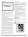
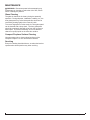
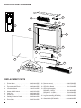
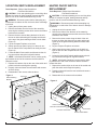
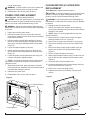
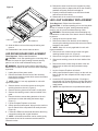
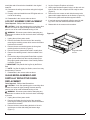
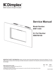
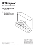
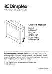
Service Manual
Model Number:
DF2000
UL Part Number
690889XXXX
IMPORTANT SAFETY INFORMATION: Always read this manual first before attempting to service this
fireplace. For your safety, always comply with all warnings and safety instructions contained in this
manual to prevent personal injury or property damage.
Dimplex North America Limited
1367 Industrial Road Cambridge ON Canada N1R 7G8
1-888-346-7539 www.dimplex.com
In keeping with our policy of continuous product development, we reserve the right to make changes without notice.
© 2013 Dimplex North America Limited
REV
PCN
DATE
00
-
13-AUG-13
7400690100R00
TABLE OF CONTENTS
OPERATION. . . . . . . . . . . . . . . . . . . . . . . . . . . . . . . . . . . . . . . . . . . . . . . . . . . . . . . . . . . . . . . 3
MAINTENANCE . . . . . . . . . . . . . . . . . . . . . . . . . . . . . . . . . . . . . . . . . . . . . . . . . . . . . . . . . . . . 4
EXPLODED PARTS DIAGRAM . . . . . . . . . . . . . . . . . . . . . . . . . . . . . . . . . . . . . . . . . . . . . . . . 5
REPLACEMENT PARTS. . . . . . . . . . . . . . . . . . . . . . . . . . . . . . . . . . . . . . . . . . . . . . . . . . . . . . 5
WIRING DIAGRAM . . . . . . . . . . . . . . . . . . . . . . . . . . . . . . . . . . . . . . . . . . . . . . . . . . . . . . . . . 6
3-POSITION SWITCH REPLACEMENT. . . . . . . . . . . . . . . . . . . . . . . . . . . . . . . . . . . . . . . . . . 7
HEATER ON/OFF SWITCH REPLACEMENT . . . . . . . . . . . . . . . . . . . . . . . . . . . . . . . . . . . . . 7
THERMOSTAT CONTROL REPLACEMENT. . . . . . . . . . . . . . . . . . . . . . . . . . . . . . . . . . . . . . 8
REMOTE RECEIVER REPLACEMENT. . . . . . . . . . . . . . . . . . . . . . . . . . . . . . . . . . . . . . . . . . 8
HEATER ASSEMBLY REPLACEMENT . . . . . . . . . . . . . . . . . . . . . . . . . . . . . . . . . . . . . . . . . . 8
POWER CORD REPLACEMENT. . . . . . . . . . . . . . . . . . . . . . . . . . . . . . . . . . . . . . . . . . . . . . . 9
FLICKER MOTOR & FLICKER ROD REPLACEMENT . . . . . . . . . . . . . . . . . . . . . . . . . . . . . . 9
LED DRIVER BOARD REPLACEMENT. . . . . . . . . . . . . . . . . . . . . . . . . . . . . . . . . . . . . . . . . 10
LED LIGHT ASSEMBLY REPLACEMENT . . . . . . . . . . . . . . . . . . . . . . . . . . . . . . . . . . . . . . . 10
LOG SET ASSEMBLY REPLACEMENT. . . . . . . . . . . . . . . . . . . . . . . . . . . . . . . . . . . . . . . . . 11
GLASS MEDIA ASSEMBLY AND PARTIALLY REFLECTIVE PANEL REPLACEMENT. . . . . 11
TROUBLESHOOTING GUIDE . . . . . . . . . . . . . . . . . . . . . . . . . . . . . . . . . . . . . . . . . . . . . . . . 12
Always use a qualified technician or service agency to repair this fireplace.
! NOTE: Procedures and techniques that are considered important enough to emphasize.
CAUTION: Procedures and techniques which, if not carefully followed, will result in damage to the
equipment.
WARNING: Procedures and techniques which, if not carefully followed, will expose the user to the
risk of fire, serious injury, or death.
2www.dimplex.com
OPERATION
Remote Operation
Figure 1
A
C
B
The controls are located on the upper right of the fireplace.
(Figure 1)
A. 3-Position Switch
The switch has two ON positions marked with “ I “ and “ II “
. The “ I “ position is for manual operation. In this position
the built-in remote control is by-passed.
The “ II “ position is for operating the unit with the provided
remote control.
When in the “ II “ position the unit is operated with the ON
and OFF buttons of the remote control. When the switch is
in the center position the unit is off.
B. Heater ON/OFF Switch
The Heater ON/OFF Switch supplies power to the heater
fan and the heater element. When the switch is in the ON
position the heater operates if the thermostat calls for heat.
! NOTE: The fan will continue running even when the
heater is not, when the Heater Switch is in the ON position.
C. Heater Thermostat Control
To adjust the temperature to your individual requirements,
turn the thermostat control clockwise all the way to turn on
the heater. When the room reaches the desired temperature, turn the thermostat knob counter clockwise until you
hear a click. Leave in this position to maintain the room
temperature at this setting. For additional heat, turn clockwise until you hear the click again and the heater will turn
on.
Resetting The Temperature Cutoff Switch
Should the heater overheat, an automatic cut out will turn
the heater off and it will not come back on without being
reset. It can be reset by switching the 3-Position Switch to
OFF and waiting 5 minutes before switching the unit back
on.
CAUTION: If you need to continuously reset the heater,
unplug the unit and call technical support at 1-888-3467539.
! NOTE: The heater may emit a slight, harmless odor
when first used. This odor is a normal condition caused
by initial heating of internal heater parts and will not occur
again.
The fireplace is supplied with an integrated On/Off remote
control.
! NOTE: Ensure that the fireplace 3 position switch is set
to the remote control setting, “II”. To operate, push the ON
button to turn fireplace on, push the OFF button to turn the
fireplace off.
! NOTE: Before attempting any operation with the remote
control, pull the plastic insulator strip out from between the
remote casing and battery cover (Figure 5).
Remote Control Initialization/Reprogram
In the event that your remote control ceases to operate
your fireplace, follow these steps to reinitialize the remote
control and the remote control receiver in the fireplace:
1. Place the 3-Position Switch (Figure 1A) in the OFF
(“O”) position.
2. Wait a minimum of 5 seconds and then place the 3-Position Switch in the Remote Control position.
3. Within 10 seconds of changing the switch position,
press the ON button located on the remote control
(Figure 2). This will synchronize the remote control and
the fireplace receiver.
! NOTE: You will have only 10 seconds to perform this
last step. Failure to do so will result in these steps needing
to be followed again.
Battery Replacement
To replace the battery:
1. Slide battery cover open on the remote control (Figure
2).
2. Correctly install one 12 Volt (A23) battery in the battery
holder.
3. Close the battery cover.
Battery must be recycled or disposed of properly.
Check with your Local Authority or Retailer for recycling advice in your area
Figure 2
ON
Button
OFF
Button
Plastic Strip
Battery Cover
3
MAINTENANCE
WARNING: Disconnect power before attempting any
maintenance or cleaning to reduce the risk of fire, electric
shock or damage to persons.
Glass Cleaning
The glass is cleaned in the factory during the assembly
operation. During shipment, installation, handling, etc., the
front glass panel may collect dust particles; these can be
removed by dusting lightly with a clean dry cloth.
To remove fingerprints or other marks, the front glass panel
can be cleaned with a damp cloth. The front glass panel
should be completely dried with a lint free cloth to prevent
water spots. To prevent scratching, do not use abrasive
cleaners or spray liquids on the clear door surface.
Compact Fireplace Surface Cleaning
Use warm water only to clean painted surfaces of the
Compact Fireplace. Do not use abrasive cleaners.
Servicing
Except for cleaning described above, an authorized service
representative should perform any other servicing.
4www.dimplex.com
EXPLODED PARTS DIAGRAM
11
2
3
5
10
4
8
6
13
12
1
7
9
14
16
15
REPLACEMENT PARTS
1.
2.
3.
4.
5.
6.
7.
8.
9.
Flicker Motor . . . . . . . . . . . . . . . . . . . .
Heater Assembly (with Cutout). . . . . . .
Thermostat with Knob . . . . . . . . . . . . .
3 Position Switch. . . . . . . . . . . . . . . . .
Heater On/Off Switch . . . . . . . . . . . . . .
Cord Set. . . . . . . . . . . . . . . . . . . . . . . .
Flicker Rod. . . . . . . . . . . . . . . . . . . . . .
Partially Reflective Panel . . . . . . . . . . .
Front Glass . . . . . . . . . . . . . . . . . . . . .
2000220100RP
2203610100RP
2600090100RP
2800071100RP
2800070700RP
4100090203RP
5902620100RP
5902580100RP
5902570100RP
10. Remote Control. . . . . . . . . . . . . . . . . . .
11. Remote Control Receiver . . . . . . . . . . . .
12. LED Driver Board . . . . . . . . . . . . . . . .
13. LED Light Assembly
DF2000L - 2 LED's. . . . . . . . . . . . . . . .
DF2000CR - 3 LED's . . . . . . . . . . . . . .
14. Felt Feet Pads (Set of 4). . . . . . . . . . .
15. Log Set Assembly (DF2000L) . . . . . . .
16. Glass Media (DF2000CR). . . . . . . . . . .
3000370500RP
3000380200RP
3001170100RP
3001180100RP
3001180200RP
8600140101RP
0478550100RP
0441480100RP
5
WIRING DIAGRAM
Units with log set
Units with glass media
6www.dimplex.com
3-POSITION SWITCH REPLACEMENT
Tools Required: Phillips Head Screwdriver
Flat Head Screwdriver
CAUTION: If unit was operating prior to servicing allow
at least 10 minutes for lights, heating elements and top
panel to cool off to avoid accidental burning of skin.
WARNING: Disconnect power before attempting any
maintenance to reduce the risk of electric shock or damage
to persons.
1. Unplug the unit from power outlet.
2. Remove the firebox from the back of the mantel by
removing the retaining screws which secure the firebox
brackets to the mantel.
3. Remove the three screws along the back of the unit,
the two on either side along the top edge and the two
at the top of the glass retaining bracket on both sides.
(Figure 3)
4. Lay the Compact Fireplace on its back.
5. Gently open the top panel, laying it on the work surface so that all of the components can easily be seen.
(Figure 4)
6. Locate the Main Power switch and disconnect the wiring connections noting their original locations.
! NOTE: A flat head screwdriver can be used to gently
pry between the end of the connector and the switch to
release the wires.
7. Depress the retainer clips on the rear of the switch and
push the switch out through the opening.
8. Properly orient and insert the new switch and connect
all of the wiring.
9. Reassemble in the reverse order as above.
Figure 3
Glass Retaining
Bracket
Top Panel
HEATER ON/OFF SWITCH
REPLACEMENT
Tools Required: Phillips Head Screwdriver
Flat Head Screwdriver
CAUTION: If unit was operating prior to servicing allow
at least 10 minutes for lights, heating elements and top
panel to cool off to avoid accidental burning of skin.
WARNING: Disconnect power before attempting any
maintenance to reduce the risk of electric shock or damage
to persons.
1. Unplug the unit from power outlet.
2. Remove the firebox from the back of the mantel by
removing the retaining screws which secure the firebox
brackets to the mantel.
3. Remove the three screws along the back of the unit,
the two on either side along the top edge and the two
at the top of the glass retaining bracket on both sides.
(Figure 3)
4. Lay the Compact Fireplace on its back.
5. Gently open the top panel, laying it on the work surface so that all of the components can easily be seen.
(Figure 4)
6. Locate the Heat On/Off switch and disconnect the wiring connections noting their original locations.
! NOTE: A flat head screwdriver can be used to gently
pry between the end of the connector and the switch to
release the wires.
7. Depress the retainer clips on the rear of the switch and
push the switch out through the opening.
8. Properly orient and insert the new switch and connect
all of the wiring.
9. Reassemble in the reverse order as above.
Figure 4
Heater
Assembly
Power Cord
Remote Control Receiver
3-Position Switch
Thermostat
Heater On/Off Switch
7
Figure 5
Retaining Screws
THERMOSTAT CONTROL
REPLACEMENT
Tools Required: Phillips Head Screwdriver
Flat Head Screwdriver
CAUTION: If unit was operating prior to servicing allow
at least 10 minutes for lights, heating elements and top
panel to cool off to avoid accidental burning of skin.
WARNING: Disconnect power before attempting any
maintenance to reduce the risk of electric shock or damage
to persons.
1. Unplug the unit from power outlet.
2. Remove the firebox from the back of the mantel by
removing the retaining screws which secure the firebox
brackets to the mantel.
3. Remove the three screws along the back of the unit,
the two on either side along the top edge and the two
at the top of the glass retaining bracket on both sides.
(Figure 3)
4. Lay the Compact Fireplace on its back.
5. Gently open the top panel, laying it on the work surface so that all of the components can easily be seen.
(Figure 4)
6. Locate the thermostat assembly and disconnect the
wiring connections noting their original locations.
! NOTE: A flat head screwdriver can be used to gently
pry between the end of the connector and the switch to
release the wires.
7. Remove the two retaining screws from the mounting
flange. (Figure 5).
8. Properly orient and install the new thermostat assembly
and connect all of the wiring.
9. Reassemble in the reverse order as above.
REMOTE RECEIVER REPLACEMENT
Tools Required: Phillips Head Screwdriver
Flat Head Screwdriver
CAUTION: If unit was operating prior to servicing allow
at least 10 minutes for lights, heating elements and top
panel to cool off to avoid accidental burning of skin.
WARNING: Disconnect power before attempting any
maintenance to reduce the risk of electric shock or damage
to persons.
1. Unplug the unit from power outlet.
2. Remove the firebox from the back of the mantel by
removing the retaining screws which secure the firebox
brackets to the mantel.
3. Remove the three screws along the back of the unit,
the two on either side along the top edge and the two
at the top of the glass retaining bracket on both sides.
(Figure 3)
4. Lay the Compact Fireplace on its back.
5. Gently open the top panel, laying it on the work surface so that all of the components can easily be seen.
(Figure 4)
6. Locate the remote control receiver and disconnect the
wiring connections noting their original locations.
! NOTE: A flat head screwdriver can be used to gently
pry between the end of the connector and the switch to
release the wires.
7. Release the receiver from the top panel by using
needle nose pliers to depress the tab on the mounting
standoffs and gently lift the receiver off.
8. Properly orient and install the new remote control receiver and connect all of the wiring.
9. Reassemble in the reverse order as above.
HEATER ASSEMBLY REPLACEMENT
Tools Required: Phillips Head Screwdriver
Flat Head Screwdriver
CAUTION: If unit was operating prior to servicing allow
at least 10 minutes for lights, heating elements and top
panel to cool off to avoid accidental burning of skin.
WARNING: Disconnect power before attempting any
maintenance to reduce the risk of electric shock or damage
to persons.
1. Unplug the unit from power outlet.
2. Remove the firebox from the back of the mantel by
removing the retaining screws which secure the firebox
brackets to the mantel.
3. Remove the three screws along the back of the unit,
the two on either side along the top edge and the two
at the top of the glass retaining bracket on both sides.
(Figure 3)
4. Lay the Compact Fireplace on its back.
5. Gently open the top panel, laying it on the work surface so that all of the components can easily be seen.
(Figure 4)
6. Locate the heater assembly and disconnect the wiring
connections noting their original locations.
! NOTE: A flat head screwdriver can be used to gently
pry between the end of the connector and the switch to
release the wires.
7. Remove the 4 screws that secure the top panel to the
heater assembly
8. Properly orient and install the new assembly and con-
8www.dimplex.com
nect all of the wiring.
WARNING: Ensure wires do not come in contact with
moving parts by securing wires in wiring tie wraps.
9. Reassemble in the reverse order as above.
POWER CORD REPLACEMENT
Tools Required: Phillips Head Screwdriver
CAUTION: If unit was operating prior to servicing allow
at least 10 minutes for lights, heating elements and top
panel to cool off to avoid accidental burning of skin.
WARNING: Disconnect power before attempting any
maintenance to reduce the risk of electric shock or damage
to persons.
1. Unplug the unit from power outlet.
2. Remove the firebox from the back of the mantel by
removing the retaining screws which secure the firebox
brackets to the mantel.
3. Remove the three screws along the back of the unit,
the two on either side along the top edge and the two
at the top of the glass retaining bracket on both sides.
(Figure 3)
4. Lay the Compact Fireplace on its back.
5. Gently open the top panel, laying it on the work surface so that all of the components can easily be seen.
(Figure 4)
6. Locate the power cord and disconnect the wiring connections noting their original locations.
! NOTE: A flat head screwdriver can be used to gently
pry between the end of the connector and the switch to
release the wires.
7. With needle nose pliers, grasp the power cord strain
relief grommet from inside the back of the bottom panel
and push while twisting to remove.
8. Install the new power cord.
9. Reassemble in the reverse order as above.
Figure 6
FLICKER MOTOR & FLICKER ROD
REPLACEMENT
Tools Required: Phillips Head Screwdriver
CAUTION: If unit was operating prior to servicing allow
at least 10 minutes for lights, heating elements and top
panel to cool off to avoid accidental burning of skin.
WARNING: Disconnect power before attempting any
maintenance to reduce the risk of electric shock or damage
to persons.
1. Unplug the unit from power outlet.
2. Remove the firebox from the back of the mantel by
removing the retaining screws which secure the firebox
brackets to the mantel.
! NOTE: Steps 3-5 are only applicable for units with
logset assemblies.
3. Remove the two screws that secure the front glass
retaining bracket to the unit. (Figure 6)
4. Remove the front glass and set aside in a safe place.
5. Remove the retaining screw in the front middle of the
grate.
6. Remove the three screws along the back of the unit
and the two on either side along the bottom edge.
(Figure 7)
7. Lay the Compact Fireplace on its back.
8. Gently open the bottom panel, laying it on the work surface so that all of the components can easily be seen.
(Figure 8)
9. Locate the flicker motor and flicker rod.
10. Locate and disconnect the 3 motor assembly wires going to the terminal block. (Figure 8)
11. Remove the 2 motor mounting screws.
12. Separate the motor from the flicker connector and
remove.
Figure 7
Front Glass Retaining
Bracket
Retaining Screws
Bottom Panel
9
10. Release the driver board from the top panel by using
needle nose pliers to depress the tab on the mounting
standoffs and gently lift the driver board off.
11. Properly orient and install the new LED driver board
and connect all of the wiring.
12. Reassemble in the reverse order as above.
Figure 8
LED Driver
Board
LED LIGHT ASSEMBLY REPLACEMENT
Tools Required: Phillips Head Screwdriver
CAUTION: If unit was operating prior to servicing allow
at least 10 minutes for lights, heating elements and top
panel to cool off to avoid accidental burning of skin.
LED Lights
Flicker Rod
Flicker Motor
Terminal Block
13. Slide the flicker rod out of the snap-in bushing and
remove.
14. Reassemble in the reverse order as above.
LED DRIVER BOARD REPLACEMENT
Tools Required: Phillips Head Screwdriver
CAUTION: If unit was operating prior to servicing allow
at least 10 minutes for lights, heating elements and top
panel to cool off to avoid accidental burning of skin.
WARNING: Disconnect power before attempting any
maintenance to reduce the risk of electric shock or damage
to persons.
1. Unplug the unit from power outlet.
2. Remove the firebox from the back of the mantel by
removing the retaining screws which secure the firebox
brackets to the mantel.
! NOTE: Steps 3-5 are only applicable for units with
logset assemblies.
3. Remove the two screws that secure the front glass
retaining bracket to the unit. (Figure 6)
4. Remove the front glass and set aside in a safe place.
5. Remove the retaining screw in the front middle of the
grate.
6. Remove the three screws along the back of the unit
and the two on either side along the bottom edge.
(Figure 7)
7. Lay the Compact Fireplace on its back.
8. Gently open the bottom panel, laying it on the work surface so that all of the components can easily be seen.
(Figure 8)
9. Locate the LED driver board and disconnect the wiring
connections noting their original locations.
! NOTE: A flat head screwdriver can be used to gently
pry between the end of the connector and the switch to
release the wires.
WARNING: Disconnect power before attempting any
maintenance to reduce the risk of electric shock or damage
to persons.
1. Unplug the unit from power outlet.
2. Remove the firebox from the back of the mantel by
removing the retaining screws which secure the firebox
brackets to the mantel.
! NOTE: Steps 3-5 are only applicable for units with
logset assemblies.
3. Remove the two screws that secure the front glass
retaining bracket to the unit. (Figure 6)
4. Remove the front glass and set aside in a safe place.
5. Remove the retaining screw in the front middle of the
grate.
6. Remove the three screws along the back of the unit
and the two on either side along the bottom edge.
(Figure 7)
7. Lay the Compact Fireplace on its back.
8. Gently open the bottom panel, laying it on the work surface so that all of the components can easily be seen.
(Figure 8)
9. Locate the LED lights along the back. Each light is
secured with four screws and there is a light filter that is
sandwiched between the light assembly and the sheet
metal bracket.
! NOTE: New light filters are not provided with replaceFigure 9
Back
Ledge
Log
Ember
Bed
Rear
Tab
Side Section
Front
Edge
10www.dimplex.com
ment lights and will need to be reinstalled in the original
locations.
10. Disconnect the wiring connections noting their original
location.
11. Properly orient and install the new LED lights and connect all of the wiring.
12. Reassemble in the reverse order as above.
LOG SET ASSEMBLY REPLACEMENT
Tools Required: Phillips Head Screwdriver
CAUTION: If unit was operating prior to servicing allow
at least 10 minutes for lights, heating elements and top
panel to cool off to avoid accidental burning of skin.
WARNING: Disconnect power before attempting any
maintenance to reduce the risk of electric shock or damage
to persons.
1. Unplug the unit from power outlet.
2. Remove the firebox from the back of the mantel by
removing the retaining screws which secure the firebox
brackets to the mantel.
3. Remove the two screws that secure the front glass
retaining bracket to the unit. (Figure 6)
4. Remove the front glass and set aside in a safe place.
5. Remove the retaining screw in the front middle of the
grate.
6. Pull the front edge of the plastic Ember Bed or plastic
grate up and forward until the rear tab releases from
the ledge located at the bottom of the Partially Reflective Panel. (Figure 9)
! IMPORTANT: Only handle the Log Set by the Ember
Bed.
! NOTE: Log Set fits tightly into firebox, some force may
be necessary to remove.
7. Reassemble in the reverse order as above.
4. Lay the Compact Fireplace on its back.
5. Gently open the bottom panel, laying it on the work surface so that all of the components can easily be seen.
(Figure 8)
6. Remove the two screws on each side that secure the
glass media support brackets to the firebox. (Figure 10)
7. Remove the glass media and the support bracket.
8. If required remove the partially reflective panel by sliding it out of the side channels towards the bottom.
9. Reassemble in the reverse order as above.
Figure 10
Support Bracket
Screws
GLASS MEDIA ASSEMBLY AND
PARTIALLY REFLECTIVE PANEL
REPLACEMENT
Tools Required: Phillips Head Screwdriver
CAUTION: If unit was operating prior to servicing allow
at least 10 minutes for lights, heating elements and top
panel to cool off to avoid accidental burning of skin.
WARNING: Disconnect power before attempting any
maintenance to reduce the risk of electric shock or damage
to persons.
1. Unplug the unit from power outlet.
2. Remove the firebox from the back of the mantel by
removing the retaining screws which secure the firebox
brackets to the mantel.
3. Remove the three screws along the back of the unit
and the two on either side along the bottom edge.
(Figure 7)
11
TROUBLESHOOTING GUIDE
PROBLEM
CAUSE
SOLUTION
General
Circuit breaker trips or fuse
blows when unit is turned on
Short in unit wiring.
Trace wiring in unit.
Improper circuit current rating
Additional appliances may exceed the current rating
of the circuit breaker or fuse. Plug unit into another
outlet or install unit on a dedicated 15 amp circuit.
Unit turns on or off by itself
Remote control has a similar frequency
to other remotes in the area.
The remote control and the remote control receiver
needs to be replaced. Reinitialize the remote control
to the remote control receiver after installation.
Radio frequency disturbance from outside sources.
Defective Remote Control Receiver
Lights dim in room while the unit
is on
Unit is drawing close to circuit current
rating
Move the unit to another outlet or install unit on a dedicated 15 amp circuit
Power cord gets warm
Normal Operation
The power cord may get slightly warm to the touch
when the heater is on
Defective power cord
Replace power cord if cord gets hot to the touch.
Appearance
Fireplace does not turn on Manu- Improper operation
ally
No incoming voltage from the electrical
wall socket
Refer to Operation Section
Check Fuse/Breaker Panel
Loose wiring
Check wiring connections
Defective 3 Position Switch
Replace 3 Position switch
Defective Remote Control Receiver
The remote control and the remote control receiver
needs to be replaced. Reinitialize the remote control
to the remote control receiver after installation.
Improper operation
Refer to Operation Section
Remote control not initialized to fireplace
Initialize the remote control
The batteries in the remote control are
dead.
Install new battery into the remote control Reinitalize
remote if necessary
Defective 3 Position Switch
Replace 3 Position switch
Defective remote control
Replace Remote Control and Remote Control Receiver, reinitialize
Loose wiring
Check wiring connections
Defective Flicker Motor
Replace Flicker Motor
Loose wiring
Check wiring connections
LED light assembly is not working
Replace LED light assembly
LED driver board is not working
Replace LED driver board
Flame Shudder
Defective Flicker Motor
Replace Flicker Motor
Light leaking around the log set
Log set not positioned properly
Check log set for proper fit
Fireplace does not turn on with
the Remote Control
Flame Frozen
Flame is not visible
12www.dimplex.com
PROBLEM
CAUSE
SOLUTION
Heater
Heater is not turning off
Improper operation
Refer to Operation Section
Defective Heater On/Off Switch
Replace Heater On/Off Switch
Defective Thermostat
Replace Thermostat
Defective Remote Control Receiver
The remote control and the remote control receiver
needs to be replaced. Reinitialize the remote control
to the remote control receiver after installation.
Improper operation
Refer to Operation Section
Loose wiring
Trace wiring in unit
Defective Heater On/Off Switch
Replace Heater On/Off Switch
Defective Heater Assembly
Replace Heater Assembly
Build up of dirt/dust in Heater Assembly
Ensure that exterior intake louvers and firebox cavity
are free of dirt/dust.
Defective Heater Assembly
Replace Heater Assembly
Normal Operation
Normal operation is when the heater emits an odor
for a brief period after the heater is initially turned on.
The heater is burning off any dust accumulated during
manufacturing or operation.
Defective Heater Assembly
Replace Heater Assembly
Heater fan turns on but heater
lacks heat
Improper operation
Refer to Operation Section
Defective heater assembly
Replace heater assembly
Heating element is glowing red
Normal Operation
Small glowing sections of the element are considered
normal.
Defective heater assembly
If larger glowing sections are causing the heater to trip
the thermal cutout, unplug unit, discontinue use and
replace heater assembly.
Normal Operation
Small glowing sections of the element are considered
normal.
Defective Heater On/Off Switch
Replace Heater On/Off Switch
Dirty Heater Assembly
Ensure that exterior intake louvers and firebox cavity
are free of dirt/dust.
Defective Heater Assembly
Replace Heater Assembly
Flicker rod hitting or rubbing against
internal components
Ensure rod is straight and mounted properly in the
bracket, spinning freely away from other components.
Replace if necessary.
Defective Flicker Motor
Replace Flicker Motor
Heater is not turning on, but
flame effect is still functioning
Heater is turning off after a
couple of minutes of operation
Heater emits an odor
Heater fan runs continuously
Noise
Excessive noise with the heater
on
Grinding or excessive noise with
the heater off
13