1
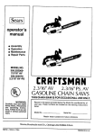
[Sears
owner's
manual
•
•
•
•
Assembly
Operation
Maintenance
Repair Parts
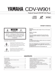
VlODEL NO.
58.353660-2.3/14"
358.353670-2.3/16"
358.353690-2.3/16"PS
CRRFTSMRH
2.3/14" Z3/16"
2.3/16"PS.
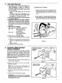
GASOLINE CHAINSAWS
THIS CHA! N SAW IS FOR OCCASIONAL
WARNING:
Carefully read and follow
Safety Rules, Precautions
and Operating
Instructions. Failure to do so can
result in serious personal
injury.
USE ONLY.
Record in the space provided below the Model No. and Serial No. o{
your saw. These numbers are located on the starting instructions
decal.
Model No.
Serial No.
Retain these numbers for future reference.
S(_L,
64765-3-06183- t -06283
s, Ro(_buck
_nd
C.o., Chic_o_),
Ill. 60.684
U.S.A.
PRINTED IN U. S. A.
FULL ONE YEAR WARRANTY ON GASOLINE CHAIN SAW
(Excluding Bar, Chain, Spark Plug, Air Filter and Starter Rope)
For one year from date of purchase, when you maintain, lubricate, and tune up this chain saw according to the operating
and maintenance
instructions
in the owner's manual, Sears will repair defects in material or workmanship in this gasoline
chain saw at no charge.
This warranty excludes the bar, chain, spark plug, air filter, and starter rope which are expendable
parts and become worn
•
_
If this chain saw is used for commercial or rental purposes, this warranty applies for only 30 days from date of purchase.
WARRANTY
IS AVAILABLE BY RETURNING THE CHAIN SAW TO THE NEAREST SEARS STORE OR SERVICE
during normalSERVICE
use.
CENTER IN THE UNITED STATES.
T_is warranty gives you specific
•
,
legal rights; and you,may
also have other rights
which vary from state to state.
Sears, Roebuckand Co., SearsTower, Dept. 698/731A, Chicago,IL 60684 -
" (
f
e
....
TABLE
. ._
"- ....
"
OF CONTENTS
Specifications
..............................
Safety Rules and Precautions ..... . ............
Know Your Chain Saw ........................
A. IntroduCtion
...........................
B. State and Local Ordinance Requirements...
C. CartGi]C0ntents
...................
.....
Preparing Your Saw For Use ...........
..........
A. Getting" Ready ..........................
B. Attaching the Handguard .... ............
C. Attaching the Bar and Chain. _,.. : ......
...
D. Chain Tension ..................
: .......
E. Engine Fuel Mixture ..................
:...
F. Barand Chain Oi1 ..................
_....
G. Optional Muffler Heat Shield Assembly
:...
Using Your Unit .............................
A. Pre-Operation Checks ...................
B. Starting Instructions
..................
..
C. Controlling Kickback ....................
2
3
4
4
4
4
5
5
5
5
7
8
9
9
10
10
10
11
Using the Power Sharp System ................
12
Types of Cutting .............................
13
A..Basic Cutting Technique ..................
13
B. Tree Felling Techniques
:.' ...............
14
C. Bucking ..................
.............
".15
. ' :,D. Debranching and Pruning ..... :.....
:. .... 16
Maintenance . _...
.. .........
................
17
A. Guide Barand Chain ............
, .......
17
B. Ignition, Cooling, and Exhaust Systems .... 19
C. Starter Rope Repairand Replacement ......
19
D. Carburetor Adjustments
..................
21
E. Air Filter ..............................
22
F. Storage ...............................
22
G. Maintenance Accessories...:
; ............
23
H. Troubleshooting
Chart ..................
24
Repair Parts .................................
26
Quick Reference Page ........................
31
SPECIFICATIONS
MODEL
CU.'IN_ DISPLACEMENT
,ii
358.353660 12,3114")
': ....
I
,
............
,GUIDE BAR- LO KICK ......................
:,,,i_,4,:"
Sprocket Nose
CHAIN - GUARD LINK
3/8 Pitch Low-Ptoffie
SPARK
358.353670 (2.3116")
2.3 cu. in. ' '
PLUG
..... "
'
(2:3116"'PLS.)
16" Sp_cket
Nose
318 Piich' LOW Profiie
'
Po,wer Sharp Chrome Cutters
Champion'CJ-8
'
'
-
MIX
'
Solid State
.010 - ,0t4:"
'
•
'........
' ....
Gasoth_elOil Mixt'u'r ,_ - t6:1-
MUFFLER
:_OIILER 'SYSTEI_:
TANK
358:353e90
025""
IGNITION
MODULE AIR GAP
FUEL
I,
""
16""Sprocket
Nose
Ch_,ome Cutters
SPARK PLUG GAP
_FUEL
:
i
CAPACITY
O'IL TANK
.....
......
' "
Choke
Knob
'
Spa_k Arresting
Automatic
11.6
".........
'' '
OZ. (343 CC.)
6,5 oz (t95 C¢,i
.....
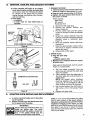
Handguard
Throttle Trigger
Ignition Switch
Fuel Cap
Rear Handle
No_
Starter Handle
Oil Cap
usting Screw
(Power Sharp Knob
,Model .353690 only)
Bal
Lever
(Models °353670 & .353690)
Lo Kick Guide Ba_r
M°del"
.353660
only}
SAFETY
RULES
--
AND
PRECAUTIONS
WARNING!
]
Failure to observe the following
Safety Rules andl
Precautions could result ,n serious personal injury. J
A.
KNOW
YOUR
D.
SAW
t. Read your Owner's Manual carefully until you
completely understand and can apply all safety rules and operating instructions before at.
.tempting to operate the unit.
2. Restdct Lthe use of your saw to users who
understand and follow
all safety rules,
precautions, and operating instructions found
in this manual.
B.
PLAN
hearing
C.
HANDLE
FUEL
WITH
E.
OPERATE
YOUR
SAW
SAFELY
1. Do not operate a chain saw that is damaged,
improperly adjusted, or not completely and
'securely assembled.
_
2. DO not operate the saw from a ladder or in a
tree.
3. Keep all parts of your body awayfrom the saw
chain when the engine is running.
4. Cut wood only.
5, Make sure the saw chain is not touching
anything before you start the engine. :_ _
'6., Use_extreme_cautioq_ when,cutting
smal{, size
brush and saplings.; Slender material may
catch the saw chain and be whipped to,ward
you or pull you off balance.
""'
7, Be,alert for springback when cutting
a limb
that is under tensionso you will not be struck
by the limb or saw when the tension in the
wood fibers is released.
8. Shut off the engine before setting the saw
down.
CAUTION
__,l;:.l_limJnat e allsources of sparks or flame in the
areas where fuel is mixed, poured, Or stored.
There should be no smoking, open flames, or
:w_ that could cause sparks:
,2. Mix!and store fue! in .a well.ventilated area.
3. Mix and store fuel in an approved, marked
container.
4:.Mo_e at least 10 feet (3 meters) away from
fuel and fueling site before starting the
engine.
5; Do.not smoke while handling fuel or while
Operating the saw.
6. Turn the engine off and let your saw cool
before removing the fuel tank cap and refueling the unit.
7. Let the saw cool in a non-combustible area,
not on dry leaves, straw, paper, etc.
8. Wipe up all spills, Wipe off fuel spilled on the
saw before using.
KICKBACK
1, Hold the chain saw firmly with both hands.
2. Do not overreach.
3. Do not let the nose of the guide bar contact
the ground, ,a log, a :branch_ or any _other
obstruction.
,_
4. Cut only with the engine running at fuli_hrot tie.
5. Do not cut above shoulder height.
6. Follow
manufacturer, s sharpening
and
maintenance instructions for the saw chain.
7. Use the Guard Link Chain and Lo Kick Guide
Bar designed for your saw to help reduce the
possibility of kickback, ,. "° -
Wear personal protective gear.
Always
use safety
f0otwear;
snug-f!tting
c|othing;
protective
gloves;
and appropriate
eye,
and head protectiondevices,
2-, Keep children, bystanders, and pets out of the
work area. Do not allow other people to be
near the chain saw when starting or operating
the chain saw.
3. Do not handle or operate a chain saw when
you are tired, ill or upset: or if you have taken
alcohol or drugs/medication. You must be in
good physical condition
and mentally alert.
4. Do not attempt to use your saw during
bad weather conditions such as strong wind,
rain, snow, etc., or at night since you would
not ha_e :good visibility.
5. Plan yo'ursawing
operation carefully in ad.
vance; DO not start cutting until you have a
clear work area, secure footing, and a planned
retreat path from the falling tree.
AGAINST
Kickback can lead to dangerous loss o f_icontrol of the chain saw and possibly cause
serious personal injury. Kickback is the upward and backward motionof the guide bar that
occurs when thesaw chain contacts an object
at the nose of the guide bar. To reduce the
hazard Of kickback:
AHEAD
%'
GUARD
Fw
MAINTAIN
YOUR
WORKING
ORDER
SAW
IN
GOOI_
1. Have all chain saw service performed by your
SEARS Service Center other than the service
described in the maintenance section of this
manual.
2. Keep fuel and oil caps, screws and fasteners
: tight.
3. Keep the handles dry, clean, and free of oil or
fuel mixture.
4. Make certain the saw chain stops moving
when the throttle trigger is released. Refer to
page 21 for carburetor adjustment instructions if the chain does not stop.
5. Stop the saw if the chain strikes a foreign object. inspect the unit and repair or replace
parts as necessary.
GI=
CARRY
SAFELY
AND
STORE
YOUR
°-_3iCarry the saw with_,,guide bar and chain
covered, preferably with an appropriate scabbard.
4. Allow your saw to cool completely before
transporting in any vehicle or storing in any
enclosure.
5. Drain oil and fuel tank before storing for more
than 30 days.
6. Store in a dry area outof the reach of children
and away from where fuel vapors can reach
an open flame from hot water heaters; furnaces, etc.
SAW
1. Never carry your saw while climbing. Both
hands are needed for safe climbing.
2. carry the unit with the engine stopped, the
guide bar and chain to the rear, and the muffler away from your body.
KNOW
A.
YOUR
CHAIN
INTRODUCTION
SAW
:.....
C.
CARTONCONTENTS
The_information found in this manual.will help
you properly prepare your chain saw -for use,
understand how to operate your saw safely, and
perform maintenance required to keep your unit
in top working condition.
After you unpack 1he carton:"
1. Check the contents against the list below.
2. Examine the items for damage.
3. Notify your SEARS store immediately if a part
is missing or damaged.
Your saw has been designed with safety in mind
and includes the following
safety features, as
standard equipment:
Handguard
Lo Kick Guide Bar
Guard Link Chain
The chain saw should never be operated unless
these devices are properly installed on the unit.
The Lo Kick Guide Bar and Guard Link Chain
have been designed to help reduce.the incident
of KICKBACK. You should thoroughly read and
_understand
the
section,
"CONTROLLING
KICKBACK"
on page 11 before operating the
--3
saw.
El
STATE
AND LOCAL
REQUIREMENTS
ORDINANCE
_Your Saw has; been; furnished with an'approved
Spark AFestorScreen
which is required in some
areas bylaw. You are legally responsible for seeing that the Spark Arrestor is properly maintained in these areas. Failure to do so could subject you to liability or to a fine. See Spark Arrestor maintenance,
page 19.
Check with your state conservation or forestry
department about regulations concerning operating your saw on forest, brush, or grass covered
areas. All U.S. forest land and the states of
California, Maine, Washington and Oregon require many internal combustion engines to be
equipped with a temperature limiting muffler by
law. Such laws require fitting your saw with an
additional muffler heat shield.
A shield which meets these requirements can be
purchased at your Sears Service Center as an
optional
accessory
kit. Ask for Muffler Heat
Shield Kit, Repair Part No. 69037.
CARTON CONTENTS
Key. No.
1
Powerhead
2
Guide Bar
3
8 oz. can 2-cycle Engine Oil
Loose parts Bag (Not Shown)
4
5
6
7
8
LOOSE PARTS BAG CONTENTS
Qty.
Owners' Manual (Not Shown)
1
Handguard
!
Cap- Handguard
1
Screw- Handguard
3
Chain
1
Bar Adjusting Tool
1
PREPARING
A.
GETTING
YOUR
SAW
FOR USE
READY
1. READ YOUR OWNER'S
FULLY.
MANUAL
CARE-
Your Owner's Manual has been developed to
help you prepare your saw for use and, to
understand its safe operation. It is important
that you read your manual completely to
become familiar with the unit before you
begin assembly,
Su
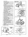
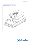
ATTACHING
THE
HANDLE-_
CAP
U
PiN
illll
Figure I
C,
Alr_,ACHiNG_THE
FOLLOWING
AVAILABLE:
a. Protective gloves
b. Approved, marked fuel container
_...
c. One gallon leaded or unleaded, regular
gasoline
d. Bar, and Chain Lubricant (see page 9).
e. Bar Adjusting Tool provided with your_unit.
One end of the tool serves as a wrench;
the other can be used as a screwdriver.
No other too! is necessary for assembly.
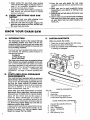
HANDGUARD
The. ;Ha,ndguardis
a, protective device designed
to help°prevent your hand from coming in contact with the cutting chain should your hand slip
off the handlebar. It will not eliminate the
possibilityof injury from kickback or loss of control of the saw.
HANDGUARD
2. HAVE THE
BAR,AND
Do not usethe
place. ....
saw.without
;WARNING!
the handguar_!':in
'
--,.
t
• Lift and carry the chain sawby the handlebar
or rear handle, not by the handguard:
• Keep the handguard securely fastened at all
times. Check the handguard
screws each
time the saw is used ......
To install:
1. Align the Handguard
and Handguard Cap
around the handlebar as shown in Figure 1.
2. Fit the mounting
pinch the Handguard into
the hole in the handlebar. Figure 1, (insert).
3. Insert the 3 mounting screws into the3 holes
on the Handguard Cap.
4. Turn each screw a little at a time clockwise,
until the Handguard
Cap and Handguard
meet and there is no 'gap between the two
parts.
CHAIN,
• Your_saw is equipped with'a Lo Kick Guide
Barand.a Guard Link Chain designed to help
reduce kickback,
• Always.use .the Lo Kick-Guide Bar and Guard
Link Chain designed for your particular chain
saw, when replacing lhese pads,
•ICAu]:ION-'twear protective gloves
_ wSemhan.
dling or operating your saw..The chain is; sharp
and can cut you even when it is not moving!
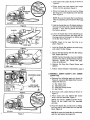
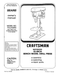
1. MODEL
.353660
(2.3/i4")
a. Remove the following
parts as sho:v_n in
Figure 2, using the Bar Adjusting Tool provided with the unit.
1.) Bar Clamp Nut.
2.) Rear Bar Clamp
3.) Bar Clamp.
Screw.
TURN
ADJUSTING
SCREW
COUNTE RCLOCKW
Figure 2
b. Turn the Adjusting
Screw counterclockwise
_
to move the Adjusting
Pin almost as far as it will go to the rear.
Figure 2.
5
c. Hold chain with cutters facing as shown in
Figure 3.
d. Place chain over and behind the clutch
drum, onto the sprocket. Figure 3.
e. Place the Guide Bar on the saw by fitting
the long slot in the Guide Bar over the Bar
Stud. Figure 4.
NOTE: Be sure the Guide Bar is positioned
with the adjusting pin hole below the large
slot.
CLUTCH '
f. Hold the Guide Bar at a 45 degree angle to
the saw and fi[the chain into the GuideBar
grooves -- first, the top groove and then,
the bottom groove.
Figure 3
CLUTCH
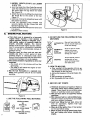
g. Lower the Guide Bar; fit the adjusting pin
into the small hole below the large slot; fit
the large slot on themounts
on either side
of the Bar Stud. Figure 5.
• h/NOTE:
Check
tO be sure
fuel
line is _in
place. Figure 5.
Figure 4
L Hold the Guide Bar against
and install the Bar Clamp.
:
the saw frame
j. Secure the Bar Clamp with the Bar Clamp
Nut, finger tight only..
NOTE: The Bar Ctamp Nut must be slightly
loose for the chain to be tensioned properly.
Securely
tighten
Bar Clamp Nut after
chain is tensioned.
k. Replace
tighten.
the Rear Bar Clamp
I: Follow "ChainTension"
Figure 5
ADJUSTING LEVER
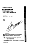
2. MODELS
.353670
(2.3116" PS)
Screw
and,
instructionsl page 7.
(2.3116")
and
.353690
,: a ._Remove :the ; foilowing :parts. as shown!in
Figure 6, using the.Ba[._djusting
Tool pro.vided with the unit.
_BAR
CLAMP
R CLAMP NUT
\
• CLAMP
SCREW
Figure 6
1.)
2.)
3.)
4.)
Bar Clamp Nut.
Adjusting Lever.
Rear Bar Clamp Screw.
Bar Clamp.
b. Hold chain with cutters facing as shown in
Figure 7.
c. Place chain over and behind the clutch
drum, onto the sprocket. Figure 7.
NOTE: For Model 353690 (2.3!16") Power
Sharp, fit the chain into the sprocket
g rooves.
d. Place the Guide Bar on the saw by fitting
the long slot in the Guide Bar over the Bar
Stud, Figure 8.
CLUTCH
Figure 7
NOTE: Be sure the Guide Bar is positioned
with the pin below the large slot.
e. HoldtheGuideBarat a 45 degree
angle to
the saw and slip the chain into the Guide
Bar grooves -- first, the top groove and
then, the bottom groove. Figure 8.
f. Lower the Guide Bar; fit the large slot on
the mounts on either side of the Bar Stud;
and slide the Guide Bar. forward.
NOTE: Check to be sure fuel line is in
place: Figure 8.
g. Hold the Guide Bar againsi thesaw frame
and install the Bar Clamp.
h. Place the Adjusting
Lever and the Bar
Clamp on the Bar Stud. Figure 9.
BAR
CUTTERS
Figure 8
;NOTE: Be sure the adjusting lever is positionedbehind
the pin in the bar.
i. Tighten
only.
the Bar Clamp
Nut, finger
,
tight
_IN
NOTE: The Bar C_amp Nut must be left
slightly loose for the chain to be tensioned
properly. Tighten Bar Clamp Nut securely
after chain is tensioned.
Jj. Replace the RearBar
tighten securely.
Clamp Screw
k. Follow
"nstructionsbelow:
'Chain Tens'on
__ADJUSTING
e.e
and
'ADJUSTING
LEVER
.....
Figure 9
D.
•
CHAIN
TENSION
• Chain tension is very important:.
--a loose chain wi!t wear the bar and itself.
--a loose chain can jump off the bar while
you are cutting.
--a tight chain can damage the saw and/or
break.
--a:chain,
either too loose or too tight, can
cause injury.
• Chain tension is correct when thechain:
:_can be lifted aboutll8'_ from the Guide Bar
at a point near the middle of_the bar, and
• _ --will move freely around the bar.
• The chain stretches during use, especially
::_;when new. Check tension:
,--Each:time
the: saw is used
_.'_:'i,i'_More frequentlyl when thechain is new
,,,,,
• The Bar Clamp Nut _must be slightly loose for
the chain to be propedy tensioned.
]CAUTION_Always wear gloves when handling
the chain. The chain is sharp and can cut you
even when it is not moving!
1, MODEL
....
.353660 (2.3/14")
ao Hold the tip of the Guide Bar up and turn
the Adjusting Screw clockwise just until
the chain does not sag beneath the Guide
Bar. Figure 10.
b. Check the tension by lifting the chain from
- 1he.Guide Bar at the center of_;the bar.
Figure 11.
.'.
c;.Continue adjusting
the, Adjustii_g Screw
until:tlle tension :is correct.
d. Hold the tipof theGuide Bar up and tighten
the Bar Clamp Nut with the Bar Adjusting
Tool.
e. Check the Rear Bar Clamp Screw-to be sure
it is secure.
f. Recheck chain tension.
CH,,N
CAN
BE
LIFTED 1t8" WHEN
TENSION IS
TURN
1t8"
TO LOOSEN
TENSION
L.
Figure 10
i
i'
Figure "11
7
2. MODEL .353670
(2.3/16") and .353690
(2.3/16" PS)
a. Hold the Guide tip of the Guide Bar up and
push the Adjusting Lever forward just until
the chain does not sag below the Guide
Bar. Figure 12.
b. Check the tension by lifting the chain from
the Guide Bar at the center of the bar.
Figure 11.
c, Continue moving the Adjusting Lever until
the tension is correct.
d, Hold the Adjusting
Lever forward
and
securely tighten the Bar Clamp Nut with
'the Bar Adjusting Tool.
e.,CheCk the Rear Bar Clamp Screw to be suie
it is secure.
f. Recheck chain tension.
E.
ENGINE
FUEL
Figure 12
MIXTURE
• Ydur chain saw is powered by a two-cycle
engine?-Which requires a fuel mixture of
regula_gasoline,
leaded or unleaded,'and a
high ,quality engine, oil- specially made- for
2-cycle,
air-cooled
engines. The internal
design of the 2-cycle engine requires lubrication of moving parts. Lubrication is provided
when you use the recommended
mixture of
gasoline and oil,
• Gasoline must be clean and not over two
months old. After a short period of time,
gasoline begins to chemically break down
and wil! form compounds that can cause hard
starting and damage in 2-cycle engines.
• The correct measure of gasoline to oil is very
importanL
--Too much oil in the mixture will foul the
spark plug.
--Too little oil will cause the engine to overheat and freeze up.
• Mix the ,fuel thoroughly in a separate container since gasoline and oil do not readily
combine,
2. DO NOT USE THEFOLLOWING
MIXTURES:
Does not have properadd-
tires for 2-cycleenginesand
could causedamage.
OIL
AUTOMOTIVE
BurnStoo hot for
_
ETHYL
GASOLINE
REMIUM or
spark plug life
i.)
FUEL MIXTURES:
SEARS #32-36555
+
ENGINE OIL
--ORANY GOOD GRADE -16:1
AIR*COOLED, 2-CYCLE
ENGINE OIL
absorbs moisture
causing acids to form
which will damage meta|
GASOHOL
and nlbber
pa.rts.
3..ow To.IX FUEL
a. Pour one-half Of.the gasoline into an approved marked container; Do not try to mix
fuel directly in the fuel tank.
b. Add entire measure of 2-cycle Engine Oil.
c. Mix.
d. Add, remainder of gasoline.
,-e. Mix thoroughly'for one minute,: •
'
4. IMPORTANT
1. USE THE FOLLOWING
and can
damage your engine.
Alcohol
_
2*_'ycle
engines; will shorten
.
Figure 13
IN FUEL
o
POINTS
a. Eliminate all sources of sparks or flame in
the areas where fuel is mixed, poured, or
stored. There should be no smoking, open
flames or work_that could cause sparks.
b, Mix and store fuel in an approved, marked
container.
c. Mix and-pour fuel in a well.ventilated area.
Gasoline vapors are harmful to your health
and are a serious fire hazard.
.d. Avoid over filling the fuel tank. Al!ow 3/4
inch for expansion. Tighten Fuel Cap
securely. Figure13.
e. Wipe up all fuel spills. Wipe off fuei spilled
on the saw before using_
f.. Move at least 10 feet (3 meters) away from
fuel and fueling site before starting the
engine.
F!
BAR
AND
CHAIN
OIL
• The guide bar and cutting chain require constant lubrication
in order to remain in
operating condition, Lubrication is provided
by the automatic oiler system when the oil
tank is kept filled.
--Lack
of oil will quickly ruin the bar and
chain,
--Too little oil will cause overheating shown
,by smoke coming from the chain andJor
,discoloration
of the guide bar rails.
e Use SEARS Bar and Chain Lubricant #36554
or clean SAE 3OW oil,
• o' InTfreezing weather oil will thicken, making it
._°-_h_b_e:ssaryto thin barand
chain oil with a
small amount of Diesel Fuel #1 or Kerosene.
Bar and chain oit must be free flowing for the
oil system to pump enough oil for adequate
lubrication.
1_ _E
THE FOLLOWING:
30°F or above--Lubricant--undiluted.
30°F- 0°F
--95% Lubricant to
, ,_;.!_'_,
:_
5% Diesel Fuel #1
or Kerosene.
Below 0°F
--90% Lubricant to
10% Diesel Fuel #1
or Kerosene.
3. IMPORTANT
POINTS
a. Fill the oil tank each time you refill the fuel
tank to ensure there will be sufficient oil for
the chain whenever you start and Fun the
saw.
b, it is normal for a Small amount of oil;to appear under the saw after the engine, stops
due to oil draining from the bar and _hain.
OIL •
CAP
2. HOWTO
FILL THE OIL TANK
a. Turn-saw on its side with oil cap up. Figure
14.
b. Loosen cap slowly; wait for pressure,in the
tank to be released before removing the
:
cap.
c. Fill the oil tank,
d. Replace the oil cap securely,
Gm
OPTIONAL
MUFFLER,
SHIELD:ASSEMBLY
HEAT
Figure 14
REMOVE STANDARD
MUFFLER
•The following
instructions have been included
to help you install the optional
Muffler Heat
Shield ,Kit,_ Repair Part No. 69037. This kit will
pf.o_(_, you_ saw with a_temperatureolimiting
•muffle/" which may be re:quired by law in some
states;,See State and Local Ordinances, page 4
for_further information.
1. Remove the screw located in the center of the
-muffler body. Figure 15.
2. Rem_o_e the muffler
b_dy'and discard.
cover
from
NOTE: Do not remove other muffler parts. If
.other parts are removed, see muffler as*
sembly in Figure 46, page 19.
3. Install the temperature
Figure 16.
limiting
4. Replace screw and tighten
F{gure 15
the muffler
muffler
INSTALL HEAT
sH i E LD COVE R
body.
securely.
JCAUTION:i Do not use an air wrench to tighten
the screw as parts can become overtightened
and damage can occur,
i
i
Figure 16
9
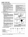
USING
A.
YOUR
SAW
PRE-OPERATION
CHECKS
Each time before operating your saw, always:
1. vCheck over safety rules and precautions in
this manual. Make certain you completely
understand "and can apply each one.
2. ,,-Check personal protective gear. Always use
appropriate eye, hearing, and head protection
devices; safety footwear, protective gloves;
and snug-fitting clothing.
3. ,,-Check the saw for loose bolts, nuts, or fittings. Tighten, repair or replace parts as
necessary.
4. ,.-Check the air filter. Clean the filter before
operating the unit.
BE
STARTING
1. IMPORTANT
INSTRUCTIONS
5. ,.-Check the saw chain. The chain should be
sharp and at the correct tension.
6. ,..Check the fuel tank and oil tank. Both tanks
should be filled.
7. ,,-Check the handles. Handles should be dry
and free of fuel mixture and oil.
8. ,..Check weather conditions. Do not use your
saw at night or during bad conditions such
as strong wind, rain, snow, etc.
9.,.-Check
the work area. KeeP children,
bystanders, and pets a safe distance away
from the work area when starting or operating
the saw.
(Refer to ,'Specifications,"
page 2, for, location
POINTS
Push saw away with right
hand while pulling starter
rope with ielt hand.
a. Hold saw firmly with the saw chain free to
turn without contacting any objecL Push
saw away from you with your right hand
whilepulling the starter rope with your left
hand. Figure 17.
b. Using no more than 15-18 inches of starter
rope per pull. Using the full length of the
rope, may cause it to break. Do not let the
starter rope snap back. Hold the handle
and let the rope rewind slowly.
C*
15-!Sinches
ol rope per pull.
Figure 17
IGNITION SWITCH
Pull rope no more than 5-6 times to avoid
flooding the engine. 8-10 pulls may be required for a new unit, a saw that has been
stored; a refueled unit which has run out of
gas.
#
s
_WI_.
•
J
Figure.18
FULL
1
Figure 19
•
._
WARNING!_
:
_
: I:"
Avoid bodily contact with the muffler when starting !
a warm engine. The muffler canbecome very hot I
and can cause serious burns.
e. Stop engine by moving the ignition switch
to the "STOP" position
Figure 18.
PROCEDURE
Turn Choke
to Full
Cl_oke
a. Cold Engine
b. Warm Engine
c. Refueled Engine after running
out of gas
d. Flooded Engine
e. Cold Weather starting
Move ignition
switch to
Start
x
(c,o,_o,_
x
x
x
x
(:,o,_of{)
x
x
x
Squeeze
ttigge_
X
X
X
Pull starter
rope until
"rum
Choke
Pull starter tope
sharply unfit
Release
trigger
engine fires
off
5-6 times
X
X
x
_
%2 times
x
X
X
x
_
8-10 times
engine tuns
m
5-6 times
" Allow engine to warm up on half.choke, then move choke to the "off"
choke at the "on" or "half" position. Figure 19.
10
,_":;
/CHOK
E
oFYF ""." HALF
STAR T-,_:-----)I,-- STOP
d. Release the trigger after engine starts,
allowing the engine to idle. The chain must
• not.mo_e when .the engine idles, Jfcormcti0n is_required,, refer to':Carburetor
Ad.
justr_ents, page 21.
2. STARTING
of controls.)
t_Ifocl_oke _
(out ol cut)
position: Do not cut with the
C.
CONTROLLING
KICKBACK
Kickback is a dangerous chain saw reaction that
can cause serious personal injury. Carefully
study this section before you make the first cut
with your new saw, You must understand what
causes kickback, how you can reduce the
chance of kickback, and how you can remain in
the best control of the saw if kickback does occur.
'1.:WHAT CAUSES KICKBACK
"V::_tKickback can happen when the moving chain
contacts an object at the tip of the guide bar.
• This contact causes the chain to dig.into the
_ _bject and stops the chain for an instant. The
result is a lightning fast, reverse reaction
which kicks the saw tip up and back at the
: operator. The operator can lose control of the
•saw and the cutting chain can cause serious
., ,,.injury if it contacts any part of the body.
.....
_
r
,
•
; KICKBACK
,1
PATH
Figure 20
AVOID
OBSTRUCTIONS
llJl
2. HOW YOU CAN
OF KICKBACK
AREA
Figure 21
NEVER
:REVERSE
HAND
POSITIONS
STAND
TO THE
THESAW
ELBOW
LOCKED
.L
THUMB ON
UNDER SIDE
HANDLEBAR
Figure 22
THE
CHANCE
a. Recognize that Kickback can happen, By
understanding and knowing about kickback, you can help eliminate the element of
surprise.
b. Avoid letting the moving chain contact any
object at the tip of the guide bar, F!gure 20.
c. Keep the working area free from:obstruc.
tions such as branches, rocks;, fences,
stumps, etc, Figure 21. Eliminate,.or avoid
any obstruction that the chaHi,:could hit
while cutting through a particdlar log or
branch.
d. Keep your saw" chain sharp and properly
tensioned. A loose or dull chain can increase the chance of kickback. ::
e_Operate2the .engine at full thro_{le for all
......cuttirlg; If the Chain is moving _'÷a slower
speed during cutting,
there i_s;greater
chance for kickback to occur.
[ Use the Lo Kick Guide Bar and Guard Link
Chain designed {or your particular saw.
These devices
have been designed
to
reduce the posibility of kickback.
g. Use extra caution if your saw is equipped
with the Power Sharp System, The Power
Sharp saw is equipped
with a Lo Kick
Guide
Bar and a Guard
Link Chain.
However, due to the chain requirements of
the built in sharpening
mechanism,
kickback force from the Power Sharp chain
may be greater than that from otherGuard
Link chains.
3. HOW YOU CAN
CONTROL
CLEAR
WQR_NG
REDUCE
MAINTAIN
THE BEST
a. Keep a good firm grip on the saw._with both
hands. F!gure 22. A firm grip:';_-an he!p
neutralize kickback,
tKeep the :_i_ige'r's of"
your qefthand-'encircling
and your left
thumb
under the: front handteb:ar. Keep
your right hand completely around the rear
handle. Keep your left arm straightwith
the
elbow locked.
b. Position
your left hand on .the front
handlebar so it is in a straight line, with your
right hand on the rear handle. Figure 22.
Never reverse right and left hand positions
on the saw handles.
c. Stand with your weight evenly balanced on
both feet.
d. Stand slightly to the left side of the saw, to
keep your body from being in a direct line
with the cutting chain, Figure 22.
e. Do not over reach. You could be drawn off
balance and lose control of the saw.
f, Do not cut above shoulder height. It is difficult to maintain control of the saw if you
cut above shoulder height.
11
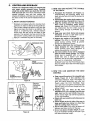
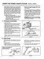
USING
THE
POWER
SHARP
SYSTEM
Model .353690 is equipped with a Power Sharp
System that will perform approximately
80% of
the sharpening necessary for the saw chain. The
Power Sharp System utilizes a built-in grinding
stone to sharpen the cutter top plates,and set
depth gauges. As the built-in sharpener is used,
the cutter side plates gradually will be altered,
About every 3rd to 5th time the Power Sharp
System is used, hand filing is required to correct
the c_btter side plates.
Replace the sharpening stone when a new
Power Sharp chain is installed. See instructions, page 13.
Remove the sharpening stone if a standard or
conventional chain is substituted for the
Power Sharp chain. See instructions for
removing the sharpening Stone and Carrier
Assembly, page 13. Use replacement chain
for Model 358..353670 (2_31t6")_ StoCk, No.
36-3629. Follow conventional chain sharpening instructions
on page 17.
• Sharpen the saw chain when:
--wood chips become small and powdery.
Wood chips made by the chain should be
about the size of the teeth of the chain.
--saw_e_uts to one side.
--saw has to be forced through the cut.
......
A:
AUTOMATICSH
ARPENING
ICAUTiON:IAIways wear gloves when handling
the chain. Th e chaincan cut you even though
it is too dull to cut wood.
.............................
1. Stop the engine.
2. Place saw on a solid, flat surface; and ensure
that the chain will not contact any object.
3. Adjust the chain with proper tension. Refer to
Chain Tension, page 7.
4. Start engine and operate at ha!f throttle.
5. Press the Power Sharp Knob down until you
feel the sharpening stone lightly contacting
the chain. Figure 23.
6. Maintain
constant,
tight pressure on the
Power Sharp Knob while 'moving the knob
side to side for 5 seconds.
7. Release Power Sharp knob and stop engine.
8. Inspect chain cutters.
INSTRUCTION
DECAL
POWER SHARP KNOB
Figure 23
TOP VIEW OF CUTTER
NOTE: A properly sharpened cutter will sflow
grinding marks across its entire width. Figure
24.
B._ _HAND
[MODEL .3536901
INSPECT CUTTERS FOR GRINDING MARKS
Figure 24
FILING:
SharpemiSaw_chain
side plates by hand after
every3rd toSth time the Power Sharp system is
used.
1. Stop the engine.
2. Adjust the chain for proper tension, page 7.
3. S0pport the square rod on the file holder (with
5t32" round file) on cutter top plate: Figure 25.
NOTE: Work at the_midpoint of the bar, moving the chain forward with a screwdriver
as
each cutter is filed.
4. Hold the file holder level with the 22 ° guide
mark parallelto
guidebar. Figure 26.
SUPPORT THE SQUARE ROD
ON FILE;HOLDER FLAT
ON TOP OF cu'n'ER
22=;
-_
•
_OUND
_
E-ILE
_.K-_A'_"_.-DEPTH
ToP
GUAGE
PLATE
SIDE
_o
PLATE
=
12
Figure 25
i ,,Hi
._l
Figure 26
5. File from inside toward outside of cutter,
straight across, in one direction only. Use 2 or
3 strokes per side plate edge. Figure 26.
SIDE
PLATE
I_
SIDE PLATE
NOTE: Avoid hitting the top edge of th.e cutters when filing the side plate.
6. Maintain a 1/'32" side plate projection. Figure
27.
7. FiJe'_all side plates on one side of the chain,
/then move to the other side of bar and fite remaining side plates.
__
Cu
i _:T
TOP /
PLATE t
_22
'
° OF CUTTER
I
Figure 27
"
REPLACE
OR REMOVE
STONE
AND CARRIER
THE
ASSEMBLY
1. :Remove bar clamp.
.2. Remove screw holding Stone, and Carrier
.-_ssembly. Figure 28.
3.'EI_ard
old assembly.
4.. Reverse procedure to install new assembly.
:5. Tighten screw securely.
STONE.&
CARRIER
r
NOTE: Be careful to not overtighten.
to 20-25 inch pounds.)
'r.r
6. ReaSsemble saw.
TYPES
OF CUTTING
A.
CUTTING
BASIC
1. IMPORTANT
_'_-
SCREW
(Torque
Figure 28
TECHNIQUE
POINTS.
a. Cut wood only. Do not cut metal; plastics;
masonry;
non-wood,
building
materials;
;_tc':
_ :b.,Slop the.'saw if the_chain strikes a:foreign objecL inspect
the unit and repair or
:• -replace parts as necessary.
-€. Keep the chain out of dirt and sand. Even a
small amount of dirt will quickly dull a
chain and thus increase the possibility of
•:.:_.,.,.,.k,i
ck back.
BE GII_I_CU'[TING WITH
THE BOTTOM OF THE
SAW FRAME AGAINST
THE LOG
2. PROCEDURE
Practice cutting a few small logs using the
following technique to get the "feel" of using
your saw before,you begin a major sawing
operation.
" '
.
.
.
a.,Accelerate-the
before entering
.engine to fu!!: throttle
the cut.
just
b. Begin cutting with the bottom of the saw
frame against the log. Figure 29.
c. Keep the engine at full throttie:.the entire time
you are cutting.
......
d. Allow the chain to cut for you; eXerf only light
downward pressure, if you force the cut,
damage to the bar, chain, or engine can
result.
e. Release the trigger as soon as the cut is completed, allowing the engine to idle. If you run
the saw at full throttle without a cutting load,
unnecessary wear will occur to the chain, bar,
and engine.
f. Stop the engine before setting the saw down
Figure 29
after cutting.
.13
Bn
TREE
FELLING
TECHNIQUES
1. PLAN YOUR SAWING OPERATION CAREFULLY IN ADVANCE
a. Clear the work area. You need a clear area
all around the tree where you. can have
secure footing.
b. Study the natural conditions that
can
cause the tree to fall in a particular direc.
lion. The tree wilt be likely to fall:
1.) In the direction the WIND is blowing
2.) towards the direction of the• LEAN of
the tree
.3-) on the side that is the HEAVIEST with
branches.
coMake sure there is enough room for the
free to fall.
d. Remove dirt, stones, loose bark, nails,
staples_ and wire from the tree where cuts
are to be made.
e.Plan
3. FELLING
LARGE
OR MORE
a. Make the notch cut. Figure 31.
1.) Cut the bottom of the notch first, about
1!3 of the diameter of the tree.
2.) Complete
the notch by making the
slant cut.
Remove the notch of wood.
b. Make the felling cut on the opposite side of
the notch about 2" higher than the bottom
of the notch.
a clear retreat path to the rear and
c. Leave enough uncut wood between the fell.!rig cut and the n0tch•.to _form a hinge.
Figure 32.
•
....
WARNING!
DO NOT CUT •
NOTE: The hinge helPS to keep the tree
from twisting and falling in the wrong direction.
--near electdcal wires or buildings.
--if you do not know the direction of tree fall.
--at night since you will not be able to see well.
--during bad weather--strong
wind, snow, rain,
etc.
d. Use a wedge if there is any chance that the
tree will not fall in the desired direction.
NOTE: Stop cutting before, the felling cut is
complete; use a wedge to open up the cut.
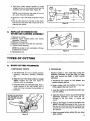
2. FELLING SMALL TREES--LESS
THAN 6"
DIAMETER
.a. If you know the direction of fall:
e. Be alert for.signs
fall:
1.) Make a single felling cut on the side
away from the direction of fall.
2.) Cut all the way through.
that the tree is ready to
1.) cracking sounds
2.) widening of the felling cut
3.) movement in the upper branches.
3_) Stop the saw, put it down, and get away
quickly on your planned retreat path.
b. If you are not sure which way the tree will
fall, use the notch method described for
felling .large trees.
,,,
DIAMETER
The notch method is used to cut large trees. A
notch is cut on the side of the tree in the
desired direction of fall. After a felling cut is
made on the opposite side of the tree, the tree
will tend to fall into the notch.
diagQnat_to the line of fall. Figure 30.
,
TREES--6"
f. As the tree starts to fall, stop the saw;put it
down, and get away quickly on your plan.
ned retreat path.
•
OPENING OF
FE LUNG CUT
FALL
_
t
,_\
÷
45°
CLOSING
OF NOTCH
HINGE HOLDS TREE ON STUMP AND
CONTROLS THE FALL,
Figure 30
Figure 31
DON'"
Figure 32
PUT YOURSELF IN THESE POSITIONS
t_
14
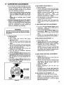
Check the wind
Don't cut down wind.
•
Checkth lean
Don'tcut on lean side.
-
Check the balance
Don't
cut On weighted side.
C.
BUCKING
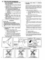
• Bucking is the term used for cutting a fallen
tree to the desired log size.
• Two types of cutting are used (Figure 33):
nOvercutting
-- begin on the top side of the
log with the bottom of the saw against the
log; exert,light pressure downward.
--Undercutting-begin on the underside of
the log with the top of the saw against the
log; exert light pressure upward. During
undercutting, the saw will tend to push
.back at you. Be prepared for this reaction
and hold the saw firmly to maintain contmL
3. BUCKING
--
USING A STAND
(Figure 36)
a, In area A:
1.) Undercut 1t3 of the way through the
log.
2.) Finish with an overcut.
b. In area B:
1.) Over cut 1/3 of the way through the;log.
2.) Finish with an undercut.
OVERCUT
WARNING!
Never>turn the saw upside down to undercut.
The sawcannot be controlled in this position.
• M_ke'-the first bucking cut-1/3 of the way "_'
_through the log and finish with a 2/3 cut on
the opposite side. As the log is being cut, it
: witl tend to bend. The saw can become pinched or hung inthe log if you make the first cut
deeper.
Figure 33
WEDGE USED TO
HOLD CUT OPEN
WARNING!
if saw becomes pinched or hung in a log, don't
try to force it out. You could lose control of the
saw resulting in serious personal injury and/or
damage to the saw. Stop the saw and drive a
wedge into the cut until saw can be removed
easily. Be;careful not to damage the chain with
the wedge. Figure 34.
Figure 34
.
.... I
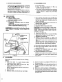
1, BUCKING m WITHOUT
A SUPPORT
a, Overcut, with a 1/3 diameter cut.
NOTE: Do not allow the chain to cut into
.:tl_e ground. Dirt will quickly dull the chain
_ _ ::and can ruin it..
,
b.Roll
log over and finish Wffh anovercut.
:
::":
"WARNING!
Always stand uphill.fromthe log being cut since
the. cut. portion will tend .to roll down hill,
2.:B_CKtNG
-- USING ANOTHER
:A_SU PPO RT (Figu re 35)
a, .!n area A:
-. t.):
I
t
LOG AS A SUPPORT
" _
Figure 35
LOG AS
Undercut 1/3 of the way through
log.
2.) Finish with an overcut.
2ND CUT
1ST CUT
;UT
the
b. In area B:
1.) Overcut, 1/3 of the way through the log.
2.) Finish with an undercut.
CUT
CUT
FIRST
CUT
Figure 36
15
D. DEBRANCHING
AND PRUNING
• Work slowly, keeping both hands on the saw
with a firm gdp. Maintain secure footing and
balance.
• Watch out for spdngpoles, Use extreme caution when cutting small size limbs. Slender
material may catch the saw chain and be
whipped toward you or pull off balance.
WARNING!
BE ALERT FOR AND GUARD AGAINT KICK.
BACK. Do not allow the moving chain to contact
any other branches or objects at the nose of the
guide bar when debranching or pruning. Allow.
ing such contact could result in serious personal injury.
• Be alert for springback. Watch out for
branches that are bent or under pressure as
you_ are cutting to avoid being struck by the
branch or the saw when the tension in the
wood fibers is released.
• Keep a: clear work area. Frequently clear
branches ou t of the way to avoid tripping over
tl_em.
WARNING!
Never climb into a tree to debranch or prune. Do
not stand on ladders, platforms, or in any position which might cause you to loose control of
the saw.
USE COMMON
SENSE
KEEP THE TREE BETWEEN
YOU AND THE SAW
1. DEBRANCHING
2. PRUNING
a. Limit debranching to limbs shoulder height
or below. Always debranch a tree after it is
cut down, Only then can debranching be
done safely and properly.
b. Leave the larger lower limbs
tree as you work.
to support the
c. Start at the base of the felled tree and work
towards the top cutting branches and
limbs. Remove small limbs with one cut;
_'d. Keep the_tree between-you and'th_ Chain.
Cut •from the side of the tree opposite the
branch you are cutting.
e. Remove larger, _upporting
branches with
the 1/3, 2/3 cuttihg technique described in
the bucking section.
1.) Start with an overcut
2.) Finish with an undercut
REMOVE SMALL
a. Limit pruning to limbs shoulder height or
below. Do not cut if branches are higher
than your shoulder. Get a professional to
do the job.
b. Refer to Figure 38 for the pruning technique.
1.) Undercut 1/3 of the waY through the
. limb nearthe trunk of the.tree.
•2.)Finish
with an overcut farther out f_om,
the trunk,
3.) Keep out of the way of the falling limb.
4.) Cut the stump flush near the trunk of
the tree.
LIMBS WITH ONE CUT"
FIRST PRUNING CUT
,,,,,,,,,,,,,,,,,,,,,,,
L,,,, i
Figure 3"/'
16
,
Figure 38
MAINTENANCE
A good maintenance program: of regular inspection and care will increase the service life and
help to maintain the safety and performance of
your saw.
• Make all adjustments or repairs (except carburetor adjustments) with:
' " ,--spark plugwire disconnected
•_#ngine,
cool as opposed to a unit that has
just been run.
Ae
,GUIDE
BAR
t
WARNING!
All chain saw service other than the maintenance described in thismanual :should be:performed by your SEARS ServiCe Center.
:
ANDCHAIN
Increase;the service life of your Guide Bar and
Chair_i!by:
_-Usihg the saw propedyand as recommended
in.,this ,lnanuaL
:
• --Maintaining
correct Chain Tension, page 7.
--Proper lubdcation, page 9.
-- Regularmaintenance as described in this section.
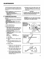
1. CHAIN,
• Check the saw for loose bolts, screws, nuts
and fittings regularly. Loose fasteners can
cause an unsafe condition as well asdamage
to your saw.
MAINTENANCE
ICAUTIONj Always wear gloves when handling
the chain, rThe chain is sha._ enough to cut you
eventhough it is too dull :to cut-wood..
,
roll
,
tsuPPO.TTHE
ISQUARE ROD ON
'THE FILE HOLDER
iON THE TOP OF
_THECUTTER
ROUND
• Sharpen the chain when:
-- wood chips are small and powdery. Wood
chips made by the saw chain should be
about the size of the teeth of the chain.
_--saw
has to be forced through the cut.
saw cuts to one side.
a. SHARPENING
INSTRUCTIONS--Models
.353660 and .353670.
Items required:
Gloves
Medium file
5/32" file
Depth Gauge Tool
6" file holder
,:l,),_,Stop engine.
_
' ;2_)_:.Adjust the chain-for
: •
- .........
proper tension,
SIDE PLATE
_
k
ii
Figure 39
HOLD 30 ° GUIDE
MARK PARALLEL
TO THE
GUIDE BAR
30°
page 7.
.3;) Work at the midpoint of the bar, moving
• the chain forward by,hand as each cutter is filed.
4.) Sharpen cutters.
, .............
,,i
Figure 40
a,) Position the file holder with the
square rod on the top plate of the
cutter as shown in Figure 39.
b.) Hold the file holder level with the
30 ° guide mark .parallel
to the
center line of the bar. Figure 40.
Co) File from inside toward outside of
cutter, straight across in one direction only. Use 2 or3 strokes per cutting edge. Figure 41,
Figure 41
17
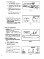
5.) Correct Depth Gauges.
a.) Place depth gauge tool over each
cutter depth gauge. Figure 42.
GAUGE
b.) File level with the flat file if depth
gauge is higher than the depth
gauge tool.
c.) Maintain rounded front corner of
depth gauge with a flat file. Figure
43.
Figure 42
NOTE: The very top of the depth
gauge should be flat with the front
half rounded off with a flat file.
, MAINTAIN ROUNDED
CORNERS OF DEPTH
•
b. CHAIN REPLACEMENT
_i!-) .Bep!ace the chain when cutters or links
break.
.
2,) See your
sears Service
Center to
_: .!_eP:lace and sharpen individual cutters
to "-match your chain,
3,) Always replace the won1 sprocket
when installing a new chain to avoid
excessive wear to the chain.
•
2. GUIDE
Figure 43
BAR MAINTENANCE
• Conditions
which can require guide bar
maintenance:
--saw cuts to one side ,
--saw has to be forced through a cut
"inadequate
supply of oil to bar and
chain.
A
FROM THE
/J
LJ
GUIDE BAR GROOVE
• Check-the condition of-the.guide bareach
time the chain is sharpened. A worn guide
bar will damage the chain and make cutting more difficult.
y.
R
..
i
• . Replacslthe guide bar when:."
, .
--tliei_ide
groove of the guide bar rails is
worn.
:---the guide bar is bent.
a.
Remove the guide bar to service.
b.
Clean oil holes at least once for each
five hours of operation.
c,
Remove sawdust from the guide bar
groove periodically with a putty knife or
a wire. Figure 44_
d.
Remove burrs byfiling
the side edges
of the guide bar grooves square with a
flat file. Figure 45:
e.
Restore square ed ge s to an uneven
.......rail
top by filing with a flat file, Figure 45.
,
.
i
i
i
Figure 44
CORRECT
GUIDE BAR
GROOVE
WORN GROOVES
Figure 45
18
FILE EDGES
SQUARE
B. 'IGNITION,
COOLING
AND
EXHAUST
• Carbon deposits will build up on exhaust
ports, spark arrestor, muffler, and spark plug
as the saw is used. All of these parts should
be cleaned at the same time to prevent
engine damage, overheating, loss of power,
and hard starting.
• Clean parts:
-- as required
--at least once for each 25-30 hours of
operation
SYSTEMS
1. EXHAUST SYSTEM
• Carbon build-up on theexhaust system can
cause the engine to loose power in a cut.
• Keep the spark arrestor clean at all times.
• Replace the spark arrestor when breaks in
the screen are found.
Items required:
Wire brush
3/8" wrench
Hardwood stick
a. Disconnect the spark plug.
b, Remove
the muffler,
baffles,
and
screen. Figure 46.
c. Pull the starter rope until the piston
moves far enough to close the exhaust
ports.
d. Scrape the carbon deposits from the
exhaustportsand
surrounding extiaust
Chamber
usir_g: a hardwood
stick.
Figure47.
:'
e: :B:low _out loos_;ned carbon withi_omo
pressed air.
f. Clean the spark arrestor screen with a
wire brushor
replace if breaks in the
screen are found.
g. Reassemble muffler parts.
BAFFLE
MUFFLER
COVER
SPARK ARRESTOR SCREEN
Figure 46
2. SPARK
PLUG
Keep the spark plug: "
--clean
--properly
gapped (.025)
• Maintenance is indicated when the engine
is hard to start.
CLEAN
EXHAUST
PORTS
Pull the rubber connector
from the
spark plug and remove the spark plijg
from the cylinder.
b. Clean deposits from the electrodes of
the spark plug with a small brush or a
pocket knife.
,
_NOTE_ _Be :careful
when _rem6ving;
- ::cleaning;'gappi_ng
and replacing" the
spark plug. If it is damaged, it wi,lt not
work properly and must be replaced.
c. Set the gap between the electrodes to
.025 using a wire or fiat gauge. Figure
48.
d. Replace the spark plug.
CHAMPION C J-8 SPARK PLUG
GAP .025"'
Figure 48
STARTER
e
:ROPE
REPAIRAND
a tooth
a.
Figure 47
C,
Item required: small brush, suchas
brush, or a pocket knife.
REPLACEMENT
A starter rope that breaks next to the pulley
can be repaired.
Replace a starter rope that breaks more than
2 or 3 inches from the pulley.
WARNING!
Always wear eye protection when set.
vicing the starter
rope. The
recoil
spring beneath the pulley is under tension. If the spdng should pop out
serious personal injury could result.
NOTE: A recoil spring lies beneath the pulley
and is under tension. If therecoil
spring is
disturbed considerable time and effort will be
required to reinstall. For this reason, you may
want to let your SEARS Service Center handle
this repair. If you do try to repair the starter
rope and the recoil spring pops out, take the
unit to your dealer.
19
1. Drainfuel tank.
2. Removethe two screwson the side of the
fan housing.Figure49.
3. Removethe largescrewat the rearof the
control handleandthe small screwdirectly
belowit. Figure50,
4. Pullthe gasline fromthe fitting goingin-the
saw handle.
5. Separatethe fan housingfromthe unit.
6. If the starterropeis not broken,releasethe
spring_ensionby pullingabout10inchesof
rope fromthe pulleyandcatch the rope in
the notch as shown. Figure 51.
.
NOTE: The tension on the starter spring will
be released if the rope has broken.
7. Turn the pulley counterclockwise
until the
•spring tension is released.
8. Remove the pulley screw in the center of the
pulley. Figure 52.
9. Lift the pulley_,arefully while gently twisting
it counterclockwise
_1_
.
10, Remo_e the old rope.
11. Move away from the fuel tank and burn the
end_efJthe rope tO be installed.
12. Pull the burnt end through a rag while the
rope is still hot to obtain a smooth end.
t3. Feed the rope through the housing and
through the round starter hole. Figure 52.
14. Put the rope into the pulley groove and up
through the hole.
15. Tie a knot in the end of the rope and pull it
tightly against the pulley.
16. Rewind all the rope onto the pulley, turning
counterclockwise
4[-,,_
17. Set the pulley into the housing; push it down
and engage the spring.
18. Replace and tighten the pulley screw.
19. Pull out 10 inches of rope and set the rope in
the notch in the pulley. Figure 53.
20. Turn the pulley 2 complete turns clockwise
winding up the spring.
21. Hold the pulley and pull the starter rope to
'the full extent of length and let the rope rewind _!owly.
:_22..Replace_the
fueI.Jine in_theostoLin
the fan
housing, Be certain fuel line is not pinched.
23. Rel_aC6: fan housing.
....
REMOVE CONTROL
Figure 50
-_ )_.,,_U-••
=
=l= ,
=
TURN PULLEY
COUNTERCL OCKWISE
NTIL TENSION IS RELEASED
i
i
Figure 52
REMOVE
FAN HOUSING
SCREWS
Figure 49
20
NOTCH
Figure 53
D. CARBURETOR""ADJusTMENTS
• The carburetor has been adjusted at the factory for sea levet conditions. Adjustment may
become necessary
if the unit is used at
significantJy higher altitudes or if you notice
any of the following conditions:
--Chain moves with the engine at idle speed.
--Loss
of cutting power which is not corrected by air filter or muffler screen clean,
inn.
--Engine
dies or hesitates when it should
accelerate.
••
Permanent_damage will occur to the engine if
•,_i,r_,_qrrectcarburetor adjustments are made,/t
is best to let your SEARS Service Center make
'carburetor
adjustments..
If you choose to
• make the adjustment ¥ourself,.observe
.the
f0]lowing procedure very Carefully.
WARNING]
Thechbirl_fnay be moving during this prbcedure,
Wear your protective gear and observe all safety
precautions.
1. PREPARATION
a. Stop :engine.
b, Use a fresh
fuel mixture
With proper
gasolineloi! ratio.
c. Place thesaw on a solid, fiat surface and
make sure the chain wil| not contact any
object.
d. Dust off the carburetor cover and surrounding area to remove debris which might fall
into the carburetor chamber.
e. Remove the carburetor,cover
'screws and
carburetor cover. Figure 55.
f. Find the three (3)carburetor
adjusting
screws. Figure 54.
g. Turn the Low Speed Mixture Screw and the
High Speed Mixture Screw clockwise just
,. ,,,:!!_Jntil_theystop, Do not turn the screws unti/
• _-_!i:__:they
are:,tight _as you may,_damage ,the nee,:die seats.
h: Turn the Low Speed Mixture Screw and the
.......High,Speed.
Mixture Screw one full turn
counterclockwise
CHOKE CLOSED
HIGH SPEED
MIX SCREW
2. IDLE SPEED
ADJUSTMENTwl
a. Start the engine,
b. Adjust if the engine stops (when the trigger
is not squeezed) by turning the idle Speed
Screw.l!2
turn clockwise
NOTE: To increase idle speed, turn the Idle
Speed Screw clockwise
_
, To
decrease idle speed, turn the idle Speed
Screw counterclockw se _
c, Run the engine for a few minutes td bring it
up to operating t,emperature,
NOTE: The engine must be at=:operating
temperature
for proper adjustmeflts'to
be
made.
3. LOW
SPEED
MIXTURE
ADJUSTMENT
a, Turn. the Low Speed Mixture Screw-slowly
clockwise,
:._--Jl_-unti! the RPM starts to
..... :.drop. Note ,the position.
_:
b: Tdrn the,_.Low_Speed :Mixture. Scr,_-counterclockwise
_
until the RPM_speeds
up and starts to drop again. Note the position.
c. Position the Low Speed Mixture Screw at
the mid-point between the two positions,
4, IDLE
SPEED
ADJUSTMENT--I!
a. Allow engine to idle:
b. Adjust if the chain is turning by turning the
Idle Speed Screw counterclockwise _.
c. Squeeze
the throttle trigger;, the saw
should accelerate without hesitating.
NOTE: It maybe:necessary
to:recheck the
low speed mixture setting after the idle
speed has been reduced by repeating Low
Speed Mixture ,Adjustment Steps.
5, HIGH
. a:.Make
SPEED
MIXTURE
ADJUSTMENT
a,test cut.
NOTE::.Take:,st_ec!a_car_e to keep chips and
dirt" out of, the carburetor.
b. Adjust if the saw smokes or Seems to have
low power in the test cut by turning the
.... -:.:High Speed,. Mixture Screw _1./16th turn
clockwise
c, Repeat test cut.
d. Repeat adjustment
until
the saw rur_s
smoothly.
CAUTION: Never set the High-Speed Mix.
lure Screw less. than 718 turn operL This is
too lean a setting and-will ruin your engine,
6. IDLE SPEED ADJUSTMENT--Ill
Recheck for proper idle mixture
IDLE SPEED
SCREW
LOW SPEED
MIX SCREW
=_
Figure 54
setting.
NOTE: It may be necessary to repeat according to instructions
in Steps 2 and 3,
Idle Speed Adjustment--I
and Low Speed
Mixture Adjustment.
21
7. CHECK
ACCELERATION
8. REASSEMBLE
Adjust if there is a slight hesitation by turning
the Low Speed Mixture Screw 1t16 of a turn at
a time counterclockwise
_
until you
have smooth acceleration,
NOTE: Check to be sure the chain is not turning when engine is idling. If chain moves at
idle speed, repeat Idle Speed Adjustm enthll.
E.
AIR
UNIT
a. Stop the engine.
b. Clean the mating surfaces
of the carburetor housing and cover.
c. Be careful when replacing the carburetor
cover to see that the choke knob operates
properly. Refer to steps 9-12, Air-Filter,
page 22.
FILTER
• A dirty air filter:.
_reduces
cutting power
:'=increases fuel consumption
• Clean the Air Filter:.
_Frequently,
especially under very dusty
conditions.
--Always after 10 tanks of fuel mixture or 5
hours
1. Ctean off the carburetor covet and the area
around it to keep dirt and sawdust from falling into the carburetor
chamber when the
cover is removed.
2. Remove the carburetor cover screws and car.
buretor cover. Figure 55.
3. Pull out the air filter.
4. Wash the filter in soap and water.
of operation whichever is less.
ICAUTION: I Do not use gasoli!_e or other flarn.
mab!e liquid•to clean the filter as this can
create a fire hazard Which Could result in
damage to the saw.
_Never
operate the unit without the air
filter,;in _laoe'as
damage to the engine can
Occur.
5. Squeeze the filter dry.
6. Add a small amount of oil to coat the filter.
NOTE: Avoid soaking the filter with oil.
7. Squeeze out excess oil
8. Replace filter by tucking- in edges and
smoothing it flush with the carburetor housing.
NOTE: Be careful when replacing the carburetor cover as incorrect placement
will
prevent the choke from working properly.
CARBURETOR
COVER
AIR
FILTER
CHOKE SHUTTER
9. Move the choke knob all the way to the right.
10. Check the choke shutter to be sure it is
closed. Figure 55.
11. Reinstall the carburetor cover and tighten
the carburetor cover screws.
t2. Check the operation Of the choke.
Figure 55
F.
STORAGE
When your saw is to be stored for over 30 days,
always:
1. D_ain fuel tank in a safe manner. (See
"Important
Points," page 8.)
2. Start engine and allow to run at an idle
speed until the engine stops.
• NOTE: This will remove most of the fuel from
the. fuel system.
3. Drain oil tank.
4. Remove, clean, and dry the bar and chain.
22
.NOTE: If the .choke knobsticks
or will not
_o_ move,':rem0ve _the.cover:" and repeat step_
9.12 above.
5.
6.
7.
8.
Store the chain in a container
filled with oil
to preventrust.
Apply a coating of oil to the entire surface of
the bar and wrap it in heavy paper, cloth or
plastic.
Clean the outside surfaces of the engine.
Store the saw in a dry place, out of the reach
of children, and awayfrom where fuel vapors
can reach open flames from hot water heater,
furnaces, etc.
,
G.
MAINTENANCE
ACCESSORIES
Available, from your nearest SEARS Store, Catalog Sales Office, or Service Center
But not furnished
Key
No.
Catalog
No.
.Part
. No.
1
2
3
-4
STD360946
3;I059
-55004
. _"55046-
5
--_
69037
44194
44204
44204
'
-
,
with your saw
Description
32-36403
Spark Plug-Champion CJ-8
---Spark Plug Wrench
32,36524 "
-File (5/32". dia.) Twin Pack_i_i
_32;36565_ '_ i ,Fite'Guide'_
,
;_ ............
32-36557 , . ' Depth Gauge .............................................
32-3617
Guard ,Link Chain (:353660--2.3/14"')
32-3629
• Guard Link Chain (.353670--2,3/16")
32-3631
Guard Link-Chain .(.353690--23/16"PS)
---Muffler Heat Shield Kit
32-36711
Replacement Recoil Cord
32-36514
Slide-on Chain Guard (all Models)
32-36621
Carrying Case
32-36555
2-Cycie Engine Oil
32-36554
Bar and Chain Lubricant
---Guide Bar--Lo Kick Replacement (.353660 - 2.3/14")
---Guide Bar-Lo Kick Replacement (.353670 - 2;3/16")
---Guide Bar-Lo Kick Replacement (,353690 - 2.3/t6" PS)
32-36618
Chain Repair Kit
23 •
H.
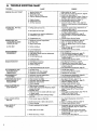
TROUBLE
SHOOTING
CHART
TROUBLE
ENGINE
CAUSE
WILL
NOT START
1.
2.
3.
4.
REMEDY
1.
2.
3.
4.
Move switch to "Start".
Fill tank with correct fuel mixture, page 8.
Install new plug, page 19.
Check for dirty fuel filter;, clean. Check for
kinked or split fuel line; repair or replace.
5. See Starting Instructions,
page t0.
6. Contact Sears Service Center.
Ignition Switch off.
Fuel tank empty.
Spark Plug not firing.
Fuel not reaching carburetor.
5. Engine flooded.
6. Compression
low.
7. Air flow restricted
ENGINE
WILL
PROPERLY
NOT
IDLE
7. Check for dirty air filtec
Check for choke shutter
page 22.
1. Idling speed set too low.
1. Adjust idle speed screw clockwise
to inincrease speed, page 21.
2. Adjust idle speed screw counterclockwise
to reduce speed, page 21.
3. See Carburetor Adjustments,
page 21.
4. Replace seals or contact Sears Service
Center.
5. Contact Sears Service Center.
2. Idle speed set too high.
3, Low speed screw requires adjustment.
4. Crankshaft seals worn.
Compression low.
ENGINE WILL NOT
ACCELERATE, .LACKS
POWER OR DIES"
1. Carburetor requires adjustment.
2. Air filter dirty.
3. Spark Plug fouled:
.
IN THE CUT
.:
.
4. Carbon build-up.
5• Low Compression.
ENGINE SMOKES
EXCESSIVELY
1.
2.
3.
4.
Choke partially on.
High speed needle requires
Air f!lter dirty.
Oil rich fuel mixture.
5. Crankcase
ENGINE
RUNS
HOT
CHAIN MOVES
iDLE SPEED
AT
adjustment.
leak.
1. Fuel Mixture Incorrect.
2. Spark Plug Incorrect.
3. Carbon build-up.
4. High Speed Mixture
OIL INADEQUATE
FOR
BAR AND CHAIN
LUBRICATION
.....
set too low.
1. Oil;tank empty.
2. Oit pump or oit filter clogged.
3• Guide bar oil hole blocked.
1•
2.
3.
4.
CHAIN CLATTERS
CUTS ROUGHLY
1. Chain tension incorrect ....
'
....
_._
C_utter_sdu{I, improperJy's_arpened;
depth '
gauges too high.
Sprocket worn•
Chain wear due to corjtact with dirt, sand
or frozen wood.
CHAIN STOPS
THE CUT
WITHIN
1_
Chain cutter tops
not filed
foreign
fiat.
2. Guide bar burred or bent; rails uneven.
3. Clutch slipping..
CHAIN CUTS AT
AN ANGLE
1. Cutters
damaged
on one side.
2. Chain dult on one side.
3. Guide bar bent, or worn.
4
Turn Choke off.
See Carburetor
Adjustments,
page 21.
C{ean or replace air filter, page22.
Empty fuel tank and refill with correct fuel
mixture, page 8.
5. Contact Sears Service Center.
1. See Engine Fuel I_ixture, page 8.
2. Replace with correct plug, page 19.
3. Glean exhaust systems including spark
arrestor, page 19.
4. See Carburetor
Adjustments,
page 21.
1.
2.
3.
4.
Chain tension too tight.
Carburetor
requires adjustment.
Guide bar rails pinched.
Clutch slipping.
after striking
1.
2.
3.
4.
1. See Carburetor
Adjustments,
page 21.
.2. Contact Sears Service Center.
CHAIN DOES NOT MOVE
WHEN ENGINE IS
ACCELERATED
Cutters damaged
material.
1; See CarburetorAdjustments,
page 21.
2. Clean or replace air filter, page 22_
3. Clean or replace Spark Plug and regap,- o.
page ;19
4_ Clean exhaust system including spark
arrestor, page 19.
5. Contact Sears Service Center.
1. Fill oil tank, page 9.
2. Contact Sears Service Center.
3• Remove bar and clean.
1. Carburetor
requires adjustment.
2• Clutch requires repair.
OR
clean, page 22.
working properly,
See Chain Tension, page 7 -8.
See Carburetor
Adjustments,
page 2t.
Repair orreplace,
page 18.
Contact Sears. Service Center.
1,:_Sse Chain Tension, page 7-_8_
_. ,.
2_ See Chain_sharpening
Instructions,
page 17 (page 12 for Power Sharp).
3. Replace.
4. Resharpen or repface Chain, page 17 & 18.
(page "12 for Power Sharp).
5. Contact Sears Service Center.
1. See Chain Sharpening
instructions,
page 17.
2. Repair or replace guide bar, page 18.
3. Contact
Sears Service Center.
1. Resharpen until all
angles and lengths,
Power Sharp).
2. Resharpen
until all
angles and lengths,
Power Sharp).
3. Replace guide bar,
cutters have equal
page 17 (page 12 for
cutters have equal
page 17 (page 12 for
page 18.
NOTES
25
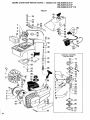
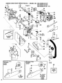
SEARS
CHAIN
SAW REPAIR
PARTS
--
MODEL
NO. 358.353660-2.3/14"
358.353670-2.3/16"
358.353690-2.3/16"
PS
Figure I
7
_9
10
Carburetor Assembly
Part No. 35158
_--11
12
_--25
1
26\
27
4
5
14
15-.J
26
18
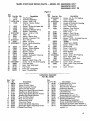
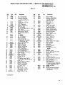
SEARS CHAIN
SAW REPAIR
PARTS --
MODEL
NO. 358.353660.2.3114"
358.353670-2.3116"
358.353690-2.3/16"
PS
Figure
Ref.
No.
Part No. Qty.
Description
1
15126
1
Key-Flywheel
2
39111
I
Flywheel Assembly
3 STD511005
1
Screw - 10-24 x 1/2
4 ' ;15428
1
Washer - Starter Pulley# 10 - flat
5 ..i: 10373
1
Starter -Pulley (!ncludes #4)
6
. _42023
1
Spring - Starter
7 -. 35158
1
Carburetor (Walbro WT-3)
8
19045
1
Gasket - Carburetor
9 STD512507 3
Screw.- 1/4,20 x 11/16
10
23791
1
Filter - Air
11
238 ! 7
2
Spring - Starter Dog
12
15127
1
Washer- Flywheel- 7/8
13 .,STD541131 1 --_Nut - 5/16-24
14
25487
1
Baffle - Air inlet
15, STD600803 2
Screw- Baffle Mounting 8-32 x 5t16
16
15245
2 .Screw - 10-24 x 1-5!8 ,
17
23865
1
Spacer- Choke Shutter
t8
15254
1
Wave Washer- 1/2
19
238O5
1
Shutter - Choke
20
238041
Trigger Throttle
21
19118:
1
Gasket - Carburetor Housing
22
23803
1
Wire-Throttle
23
23366
1
Reed Valve
24
23367
1
Washer - Reed Valve - # 6
25 STD610803 1
Screw - No, 6-19x 5116 Tapping
26
23808
1
Fuel Cap Assy,
27
19093
1 •Seal- FueITank
Neck
28
25143
1
Fuel Tank
Fuel Line - Carburetor
29
21025:
1
30
23373
1
Boot - Throttle Wire
Ref.
No.
Part No, Qty.
31 STD610807
1
32
24967
1
33 STD512507
1
34
25233
1
35
23877
1
38
21024
1
37
15252
1
38
39
40
41
42
• ,,43-
23364
23363
23783
11869
15406
1
1
t
1
1
44
4546
47
48
49
50
51
52
53
54
55
25536
25538
15229
23807
25063
15168
15147
23806
STD600803
3934
3933
39087 .
STD510807
39082
1
1
2
1
1
2
1
t
1
!
1
1
2
1
56
24158
Description
Screw - No. 8 x 3/4 Tapping
Cover- Handle
Screw 1/4-20 x 3/4
Handle & Carburetor Housing
Fitting - Fuel Line
Line - Fuel Pick-up
:Washer- Fuel_Pick-up
(nylon) 15/16 x 1/2
Filter- Fuel
Weight- Fue! Pick-up
Rope & Handle-Starter
Fan Housing
:-Screw - 10-24 x ½ slottedPan
Hal,
.:.DecaJ.- Fan Housing
,, i353660
.353670 and .353690
Screw - 10-24 x 1-3!8
Choke Knob "
Cover - Carburetor
Screw - 10-24 x 5t8
Wave Washer
Lever - Choke
Screw - 8-32 x 5f16 Tapping
Boot L'Spark Plug
ConnectorSpark Plug
Module Ignition
Screw - 8-32 x 3t4 Sems
Lead - Spark Plug (includes
50 & 5t)
Lead - Switch
Carburetor Assembly
Part, No. 35158
Key °'_:Part '
No.._ ;_No.
1 '_5006
2 35015
3 35034
A
35024
5 35023
6 35171
7 35167
8 35169
9 _35182
10 35163
11
35017
12 35159
13
35035
t4
35168
15 35164
Description
Valve Throttle
' Screw-Throttle
Valve
Shaft Assembly-Throttle
Spring-Throttle
Return
Spring-Low Speed Mixture Needle
Needle-Low Speed Mixture
Spring-High Speed Mixture Needle
Needle-High Speed Mixture
*Plug -5116 Dia, Welch
*Plug -1/4 Dia. Welch
Screw-Pump Cover
Cover-Fuel Pump
Screw-Idle Speed Adjusting
Spring-Idle Speed Adjusting
Screw
+ *Gasket-Fuel
Pump
Key
No. Part No,
16
35166
17
35172
18
35007
19
35008
20
35139
21
35031
22
35028
23
35016
24
35165
25
35014
26
35003
27
35021
35161
-35173
'Description
+ ' Diaphragm-Fuel
Pump
*Screen-Fuel
Inlet
: Ring_Throttle
Retainer
*Valve-inlet Needle
*Spring-Metering
Lever
*Lever-Metering
*Pin-Metering
Lever
*Screw, Metering Lever Pin
+ *Gasket-Metering
Diaphragm
+ *Diaphragm-Metering
Cover-Metering
Diaphragm
Screw Assembly-Metering
Cover
Kit-Repair (includes parts marked *)
Kit-Gasket/Diaphragm
(includes parts
marked +)
_-
27
SEARS
_-1
CHAIN
4
SAW REPAIR
-
20
PARTS
--
MODEL
Figure 2
NO. 358.353660-2.3114"
356.353670-2.3116"
358.353690-2.3116"
PS
76
36
>.
\
For Model
.353660
56
40
4]
57
13
58
Sprocket & Chain
For Model
.353690
71
SEARS CHAIN
SAW REPAIR
PARTS
--MODEL
Figure
ReL
Nm
1
2
3
,
Pad
No.
23792
15249
10469
" Qt_
1
1
:1
23824
5
6
7
.8
9
10
11
12
13
14
1
19059
2
19089
1
_STD541408
1
:23492
1
!;.15236'"
" 1
._!1204..
!
69097,
1
1697
1
15173
1
15
16
51194
51242
44194
10158
1
1
1
1
17
48049
1
19
20
21
22
23
24
25
26
27
28
29
30
31
32
33
34
35
36
37
23519
STD5t0805
19091
23802
32026
32065
22172
21026
23887
23653
_23656
ST_600603
_1949
23874
:10221
1
2
2
1
2
1
1
1
1
1
1
1 _"
1
1
1
23801
10195
15486
32075
1
1
2
1
.25474
25565
1
1
40
15505
2
41
42
1642
STD511015
t
1
, .38
39
Descdption
Pin - Oil Tank Vent
Stud - Bar Mounting
Crankcase Assembly.
(incL 1,2,4, 5, 6, 7, 8, 9
NO. 358.353660-2.3/14"
358.353670-2.3116"
358.353690-2.3116"
PS
2
ReL
No.
43
44
45
46
&23)
47
Check Valve _ Oil Tank
48
.Pressure
Seal - Crankshaft
49
Gasket - Check Valve
50
Lock Nut - 8-32
Pin ,.Bar Adjust.
Screw _8_r AdjL_¢t:_8-32x
1.-5/8' 51.
Hub -Clutch
52
53
Shoe- Clutch (incL Qty. 2)
54
Garter Spring - Clutch
55
Thrust Washer (outside)
Chain
56
14'L.353660
57
58
16"-.353670
Bar -14"-.353660
59
6O
Clutch Assembly
61
(incl. 10, 11,& 12)
62
Sprocket
& Drum _.353660
63
& .353670 (incl. 18)
64
Spacer -'Clutch (inside)
65
Screw -8-32 x 1/2
66
Gasket - Oil Pump
67
Cover- Oil Pump
68
Bearing- Crankshaft
69
Bearings - Roller
(incL 12 bearings)
70
Crankshaft (Solid State)
7t
Line- Oil Discharge
72
Thrust Washer --Crankshaft
73
Chain - Oil Cap
74
Retainer - Chain
75
Screw, 8-32 x 5/16
O-Ring - Oi! Cap
.76
Cap - Oil
77
Oil Cap Ass'y, (incl. 28, 29,
78
• 30, 31, 32, 42, 43, 44, 45 & 46)
79
Filter- Oil
80
BOdy Assembly - Oil Pump
WasherRod (Top)
Bearings - Rod (Top)
(incl. 21 bearings)
Connecting
Rod
Spacer
Bott - 1!4.20 x t-11/32
(Handlebar & Isolator)
Lockwasher
- t/4"
Screw - 10.24 x t-7!16
Pad
Nm
23795
23843
10474
25572
25568
48067
51234
44204
._23535 ''23796
10471
23788
23786:
STD511007
25567
015515
STD511005
19O88
25467
23787
STD610805
23797
23794
22245
025631
24091
15231
25566
25569
15507
STD360946
11861
15239
31063
30054
24049
15509
52044
52055
64765
25612
Qt_
Description
1
2
t
Cover -Muffler
Retainer-Piston
Ring
Connecting'Rod
Assay,
(inc!. 36, 37 & 38)
1
Bracket Isolator
1
Pad - Cork
1
Drum .& Sprocket.353690
1
Chain - t6"-.353690
1
_Bar and Pin Ass'y..353670 & .353690
• 1 . .Spacer- Muffler Cover
-1
•Screen, Spark Ar_re.stor
1
Piston Kit (incl. 44 & 61)
1
Knob Ass'y.-Switch
1
Ramp, *.Switch
7
Screw - 10.24 x 111t6
2
Cup-ls01ator
1
Lock Nut - 1/4-20
2
Screw- 10-24 × 112
1
Gasket -Cylinder
1
Piston Ring
1
Clamp - Switch
1
Screw * No.B x 9/16 Tapping
2
Baffle - Muffler
1
Body - Muffler
1
Handlebar
DecaI-Handguard
1
Handguard
1
Pin - Bar & Pin Ass'y._.353690
1
Isolator
1
RetainerScrew
2
Screw -'10-24 x 518 Hex Head
1
Spark Plug - CJ-8
1
Cylinder
2
.Screw _ 1/4-20 x 3t4 'Socket
Head
1
_Bar._.djusting
Tool
AR*
Sealant - Crankcas e (Optional)
1
Cap - Handguard
3
Screw --Plastite - # 10 x 1
Chain Repair Kit
(both.kits
inc!ude 1 Drive link,
2 Preset tie straps_2 Plain tie
straps, 1 Guard di_ive link)
AR*
.353660 & .353670 .
AR*
.353690
AR*
Owner's Manual (not shown)
Label Warranty - Guide Bar
(not shown)
*As Required
29
SEARS CHAIN
SAW REPAIR
PARTS
LIST
Figure 3
Figure
3_._.
-__.
_-_-
1...._j..._
I___
5.__
MODELS
:_.-_:- _..
• 4__-_1
3A
.353660
2.3/14"
Key
_ L.______6,
No.
Description
Qty. Decal - Bar Clamp
1 Nut - Bar. Mounting
- 5/16 - 18 Flange
1 Decal - Instructions
1
(Left Half)
Decal - Instructions
(Right Half)
Screw - 10-24 x 7/8
Bar Clamp
PartNo.
2
STD541431
3
1
25527
25535
4
25525 ,
Figure
MODEL
2
Key
No.
1
2
Part No.
25537
STD541031
3
4
5
25257
23764
25528
6
25525
7
8
3B
.353670
2.3/16"
Qty. Description
1 Decal * Bar Clamp
1 Nut-5/16-t8Bar Mounting
1
Level - Chain Adjust
1 Knob - Chain Adjust
• 1 Decal - Instructions
(Left Hal0
1 Decal - Instructions
(Right Hal0
1 Screw - 10-24 x 7/8
!
Bar Clamp
STD5110t0
11871
Figure 30
MODEL
.353690
2.3H 6', PS
"-
Key
No.
1
Part No.
STD541031
2
3
4
5
6
7
8
25257
23764
23759
23762
23761
25537
25529
25531
3O
10
25525
11
12
13
STD5t1010
11873
69027
14
15
STD511002
69026
,
.
.
, 4
Qty. Description
1: Nut-Bar
Mounting
- 5/16 - t8
1 Lever - Chain Adjust
1 Knob - Chain Adjust
.1
Knob Sharpening
1 .Spring
1 Washer
1
Decal- Bar Clamp
1
Decal - Instructions
(Left Hal0
1
Decal - Sharpening
Instructions
1 Decal - Instructions
(Right Hat0
1 Screw - 10-24 x 7/8
1
Bar Clamp
1 Arm-Sharpening
Stone
(IncL 15)
1 Screw -10-20 x 1/4
1 Stone & Carrier Ass'y.
(Incl. 14)
QUICK REFERENCE
PAGE
Read and follow aft Safety Rules, Precautions and Operating Instructions.
Failure to do so can result in serious personal injury.
page
SAFETY RULES AND PRECAUTIONS.
PBEPARATION.
....................................................
3-4
. ..........................
t. _-_
Wear
personal protective gear -- gloves; safety footwear, snug fitting clothing;
:: hearing, and head protection.
2._,_ Check saw for worn, loose, or damaged parts and repair or replace if necessary.
3._ Check thechain for sharpness and tension.
4:
Keep children, bystanders and pets out of the work area.
5.
Plan your sawing operation carefully in advance.
_. . .3
and appropriate
eye,
FUEL AND OIL
STARTING
is mixed, poured, or stored.
THE ENGINE
...........
.. ...........................................
1o
Hold saw firmly with the sawchain
free:t0 turn without making contact with any object.
Push saw away from you with your right hand while pulling the starter rope with your left hand.
Use no more than 15-18 inches of rope per pull.
Pull rope no more than 5-6 times.
Release the trigger after engine starts allowing engine to idle.
17
....
T
................................
soon as the cut is completed.
setting the saw down after cutting.
_
MAINTENANCE
:. 13
to full throttle before entering the cut:
saw frame up against the log.
......
Cut wood only.
Accelerate
the engine
Begin cutting with the
Cut only at full throttle.
Release the trigger as
Stop the engine before
........................................................
,
THE SAW..
................
OPERATING
1.
2.
3.
4.
5.
6.
or flame where fuel
#o
1.
2.
3.
4.
5.
of:sparks
................
7.
all sources
..
5.
6.
Eliminate
Use1 part air-cooled;:2_cycle
engine Oil _to,:16parts: !e_ded or unleaded r_egular::gaso!!n_.
Use gasoline not over 2 months old.
Mix and store fuel in an approved; marked container.
Mix and pour fuel in a well-ventilated
area.
Move a minimum of 10 feet away from fuel and fueling site before starting engine.
Fill the oil tank each time the fuel tank is refueled.
....
.
.. 8-9
1. :!: Adjustor
have,theTcarburetor,adjusted_if
the chain: moves When _tI_e engine idles.
2. _ Check the guide bar forweaF.each :time the chain is sharpened.
3., Clean the air filteF frequently:andalways
after 1Otanks of fuel mixture or 5 hours of operation, whichever
is less.
4.
Cle_n:ignition;cooitng_ande×haust
systems at least once f0r,each 25-30 hours of operation.
5. : Drain fuel tank inasafemannerafter,
eachuse.
6.
Store saw in a dry place out of the reach of children.
WATCH OUT FOR
KICKBACK
b DO J
NOT USE
THE SAW WHEN
IT NEEDS REPAIR
NEVER USE THE SAW
WHEN TIRED
USE A FIRM GRIP _
"
J,,,,,,u,
3!
The Model Number
will be found under the handle with the Serial
Number. Always mention the Model Number when requesting
vice or repair parts for your Chain Saw.
ser-
All parts listed herein may be ordered from any Sears Service Center
and most Sears Stores.
WHEN
ORDERING
REPAIR
PARTS,
FOLLOWING INFORMATION
AS SHOWN
L
The PART NUMBER
3.
The PART DESCRIPTION
2.
The MODEL NUMBER
358.353660-2.3H 4"
358.353670-2.3/16"
358.353690-2.3116" PS
4.
The NAME OF ITEM
Chain Saw
358._353670-2,31161''
358'353690-2,3116
PS
Repair
locally,
Repair
When you
from Sears
something
can offer ...
358.353660-2.3114"
How
THE
1.
If the parts you need are not stocked
electronically
transmitted
to a Sears
center for expedited handJJng:
"
MODEL NO.
ALWAYS
GIVE
IN THIS LIST.
your order will be
Parts Distribution
buy merchandise
you get an extra
that nobody else
Sears Service.
Across
town
or across
the
country, Sears Service follows
you, providing--trustworthy;
........
competent service technicians
using
only sears
specified
factory parts.
to Order
Parts
SEARSSERVICE
Sea_-s,
¢o4765-3-06i83-1_062_3
Roebuck
and
Co.,
Chicago,
In_ 60684
U.S.A.
' PRINTED
IN U.S,,A,