1
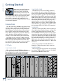
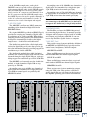
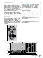
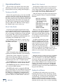
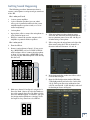
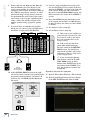
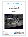
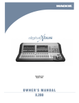
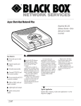
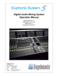
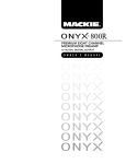
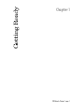
QUICK-START GUIDE
dXb.200
dXb.200
Table of Contents
Introduction................................................................................................................3
Getting Started..........................................................................................................4
Connections.................................................................................................................................................4
I/O Cards.............................................................................................................................................................................. 4
1. MIC/LINE 4 CARD............................................................................................................................................................................................ 4
2. MIC/LINE 8 CARD........................................................................................................................................................................................... 4
3. LINE CARD.......................................................................................................................................................................................................... 4
4. DIGITAL CARD .................................................................................................................................................................................................. 4
5. AES/EBU CARD..................................................................................................................................................................................................5
6. FIREWIRE CARD ................................................................................................................................................................................................5
7. MIX OUT Card....................................................................................................................................................................................................5
8. SYNC CARD ....................................................................................................................................................................................................... 6
Other Connections............................................................................................................................................................. 6
9. FOOT SWITCH 1 and 2..................................................................................................................................................................................... 6
10. SERIAL 9 PIN.................................................................................................................................................................................................... 6
11. MIDI IN and OUT ............................................................................................................................................................................................ 6
12. ETHERNET ........................................................................................................................................................................................................ 6
13. USB ..................................................................................................................................................................................................................... 6
14. IEC Power Receptacle................................................................................................................................................................................... 7
15. Power Switch................................................................................................................................................................................................... 7
More Connections...............................................................................................................................................................7
16. Mouse................................................................................................................................................................................................................ 7
17. Keyboard........................................................................................................................................................................................................... 7
Operational Basics.................................................................................................................................... 8
Turning on the dXb ............................................................................................................................................................ 8
About Fader Banks............................................................................................................................................................. 8
About V-Pot Controls........................................................................................................................................................ 8
Touchscreens........................................................................................................................................................................ 8
Keyboard and Mouse......................................................................................................................................................... 8
Getting Sound Happening...................................................................................................................... 9
Hookup Diagrams.................................................................................................... 12
Don’t forget to visit our website at www.mackie.com for
more information about this and other Mackie products.
Part No. 0012120 Rev. 2 8/04
©2004 LOUD Technologies Inc. All Rights Reserved. Printed in the USA.
2
dXb.200
Thank you for choosing a Mackie dXb for your
next-generation digital recording console. The dXb
offers you the flexibility to configure it for virtually
any recording application through its extended card
cage and I/O routing options. It was designed with
the ability to upgrade as advancements are made in
digital recording technology. But with 32-bit floating
point processing, you have more power than just about
any other digital mixing console in its class.
We know you want to get started right away, so
this Quick-Start Guide is designed to help you get
up and running quickly. If you have experience
using a digital mixing console, like our D8B, you’ll
find that using the dXb is very similar and you’ll be
mixing away in no time. If this is your first experience with digital mixing, we’ll run you through
some of the unique aspects of using a digital mixing
console. You will find that once you’ve learned these
differences and the incredible flexibility that digital
mixing has to offer, you will have a very short learning curve, and wonder how you have lived without
the power of digital mixing for so long.
Note: As new software releases become available, they can be downloaded from the Mackie website by
going to the dXb webpage at:
http://www.mackie.com/products/dxb.
You will need a USB flash drive (a.k.a. thumbdrive) to transfer the installer package from your
computer to the dXb. Installation instructions are
also available on the website.
HOW TO USE THIS MANUAL
Quick-Start Guide
Introduction
We know that many of you can’t wait to get your
new dXb hooked up, and you’re probably not going
to read the manual first (sigh!). So this Quick-Start
Guide will help you get the mixer set up fast so you
can start using it right away. After the "Getting
Started" section, we have included some hook-up
diagrams that show typical connections for tracking, mixdown, and using the dXb with a DAW (Digital Audio Workstation).
Then, when you have time, read the owner's
manual. It describes every knob, button, and slider
on the console, and all the menus and windows on
the touchscreens.
Please write your serial number here for future
reference (i.e., insurance claims, tech support,
return authorization, etc.)
Purchased at:
Date of purchase:
Quick-Start Guide
3
dXb.200
Getting Started
2. MIC/LINE 8 CARD
Once you’ve unpacked your new
dXb, you’ll want to position it
where you can sit comfortably
and reach the touchscreens and
controls, and have relatively easy
access to the rear panel, in case you need to make
any changes to the connections. Typically, once
you’ve set it up and made the connections, you
won’t have to make any changes unless you change
your external equipment.
The Mic/Line 8 card has two DB25 connectors,
one for inputs and one for outputs. The input connector accepts eight balanced mic/line-level inputs.
The output connector provides eight balanced linelevel outputs. These DB25 connectors use the TASCAM standard pinout for analog signal connections
(the same standard used on the analog cards for the
Mackie D8B and Hard Disk Recorder). If you are
connecting these to another device using the same
DB25 standard, you can use a DB25-to-DB25 audio
cable. Otherwise, you will need to use DB25 cables
that breakout to XLR, 1/4" TRS, or TT connectors.
Connections
The dXb comes with a Mix Out card (control room
card) and a Sync card already installed in the card
cage in the rear panel. There are also connections
for a USB mouse and keyboard (see "More Connections" for PS/2-style mouse and keyboard connections). While not required to operate the dXb, they
can be handy for quickly entering data or when
clicking is easier than touching (the touchscreen).
3. LINE CARD
The Line card has two DB25 connectors. One provides eight balanced line-level inputs, and the other
provides eight balanced line-level outputs. They
use the TASCAM standard pinout for analog signal
connections (the same standard used on the analog
cards for the Mackie D8B and Hard Disk Recorder).
If you are connecting these to another device using
the same DB25 standard, you can use a DB25-toDB25 audio cable. Otherwise, you will need to use
DB25 cables that breakout to XLR, 1/4" TRS, or TT
connectors.
Depending on your particular configuration and
requirements, we have a variety of analog or digital
I/O cards, not included with the base model, that
you can install in the card cage to suit your application. Here’s a quick run-down of what we offer:
Refer to Appendix C in the dXb.200 Owner's
Manual for a wiring diagram of these connectors.
I/O Cards
4. DIGITAL CARD
1. MIC/LINE 4 CARD
This card provides eight channels of digital I/O in
two formats; TDIF on a DB25 connector and ADAT
optical on four TOSLINK connectors.
This card has four female XLR balanced microphone inputs, and four 1/4" TRS balanced/unbalanced
line-level inputs, for a total of eight analog inputs.
Note that this card does not provide any outputs.
��������
����
���������
���������
������������
������������
���������
���������
��������
���������
���������
���������
���������������
��
���������������
���������������
�
�
�
�
�
�
�
�
��
����
�����
�������
���
����
���
���
���
���
���
�����
��
��
���
�������
�����
���
���
����
��������
�
�
�
�
����
��
��
��
�
�
�����
�
������
�
�
�
�
�
�
�
�
�
�����
�
4
dXb.200
�������
�
5. AES/EBU CARD
The AES/EBU card has one DB25 connector,
providing eight channels of digital I/O in the
AES/EBU format.
At sampling rates of 88.2/96 kHz, two channels of
digital audio are transmitted on a single wire (one
3-pin XLR) at twice the normal speed (2x).
At sampling rates of 176.4/192 kHz, two channels
of digital audio are transmitted on a single wire (one
3-pin XLR) at four times the normal speed (4x).
Note: Check the owner’s manual for the device you
are connecting to the AES/EBU card, to find out if
it supports the double-fast (or single-wire) method.
6. FIREWIRE CARD
The original AES/EBU specification (IEC958 Type 1)
provides for carrying two channels of digital audio
at resolutions up to 24-bit at 48 kHz. When higher
sampling rates became possible, two methods were
developed to transmit digital audio at the higher
sample rates — double-fast and double-wide.
The double-fast method (also called single-wire)
clocks the digital I/O port at twice the speed to get
twice the information through, providing support for
resolutions up to 24-bit at 96 kHz.
The FireWire card uses the IEEE-1394 protocol
for connecting digital devices. It currently provides
16 inputs and 16 outputs of digital audio at 48 kHz,
and 8 inputs and 8 outputs at 96 kHz. It can connect to any FireWire capable device or computer.
7. MIX OUT Card
This provides several outputs (with the addition of
an AES/EBU and S/PDIF input), typically used for
control room, headphones, and main outputs.
AES/EBU IN and OUT
The double-wide method (also called dual-wire)
transmits one channel of digital audio instead of two
channels through a single digital I/O port, again providing support for resolutions up to 24-bit at 96 kHz.
These are XLR connectors that accept and send
standard AES/EBU two-channel digital signals.
The AES/EBU card currently uses the double-fast
method, so eight channels of digital I/O are supported up to 192 kHz.
These are RCA-type connectors that accept and
send standard S/PDIF two-channel digital signals.
At sampling rates up to 48 kHz, two channels of
digital audio are transmitted on a single wire (one
3-pin XLR) at normal speed as specified by the
AES/EBU standard.
These are two sets of stereo monitoring outputs
using 1/4" TRS jacks. They produce a line-level
analog signal that you can connect to the inputs of
the amplifier powering your control room monitors
��������
����
���������
���������
������������
������������
S/PDIF IN and OUT
SPEAKERS A and B
���������
���������
��������
Quick-Start Guide
At 44.1/48 kHz sample rates, each optical
TOSLINK connector provides either eight inputs or
eight outputs of digital audio. At 88.2/96 kHz sample
rates, the S/MUX protocol is used to provide channels 1-4 on the “A” connectors, and channels 5-8 on
the “B” connectors. At 176.4/192 kHz sample rates,
the S/MUX II protocol is used to provide channels 1-2
on the “A” connectors and channels 3-4 on the “B”
connectors, for a total of four inputs and outputs.
���������
���������
���������
���������������
��
���������������
���������������
�
�
�
�
�
�
�
�
��
����
�����
�������
���
����
���
���
���
���
���
�����
��
��
���
�������
�����
���
���
����
��������
�
�
�
�
����
��
��
��
�
�
�����
�
������
�
�
�
�
�
�
�
�
�
�����
�
�������
�
Quick-Start Guide
5
dXb.200
(or the inputs to your active studio monitors). You
might use one pair (A) for near-field monitor speakers and the other pair (B) for your main monitor
speakers. These are assigned to the Control Room
Left and Right outputs by default, but can be reassigned to virtually any input or output source.
Other Connections
The Control Room source is selected in the
CONTROL ROOM section of the console (press the
SETUP button in the CONTROL ROOM section for
more setup options).
These two 1/4" TS jacks are provided for footswitch control of various functions. These functions
are assignable in the Windows > Setup window, and
include Talkback, Play/Stop, Next Marker, Previous
Marker, and New Marker.
PHONES 1 and 2
These are stereo 1/4" TRS jacks that provide a
stereo output for headphones, or for connecting to a
headphone distribution box. These are assigned to
the Phones 1 and Phones 2 outputs by default, but
can be reassigned to virtually any input or output
source.
The Phones 1 and 2 sources are selected in the
PHONES 1 or PHONES 2 section on the console
(press the SETUP button in the PHONES section for
more setup options).
MIX OUT
These are balanced 1/4" TRS jacks that provide
a line-level analog signal. These are assigned to
the left and right mix outputs by default, but can be
reassigned to virtually any input or output source.
Connect these outputs to the inputs of a 2-track
recorder for mixdown, or to the inputs of a power
amplifier to drive a pair of speakers for the studio or
whatever.
8. SYNC CARD
The Sync card provides the digital word clock in
and out on a pair of BNC connectors, and SMPTE
time code in and out on a pair of 1/4" jacks.
Sync data is also transmitted through the ADAT
lightpipe and AES/EBU connections. The Sync card
just provides another means to transmit and receive
the word clock. This is particularly useful when you
want the dXb to be the master clock for your digital
audio system.
Time code is also provided through MIDI time
code (MTC). SMPTE time code is more commonly
used in motion picture and broadcast applications.
USB
6
dXb.200
ETHERNET
MIDI
IN
MIDI
OUT
In addition to the cards in the card slots, there are
more connections you can make on the rear panel.
9. FOOT SWITCH 1 and 2
10. SERIAL 9 PIN
This DB9 connector is an RS-422 port that supports the Sony® 9-Pin device protocol. It is configured to operate as a controller, so it should be
connected to a device (DEV) that is configured to
be controlled by a controller (CONT). This is used
primarily to transmit tape transport commands from
the dXb to a recorder.
11. MIDI IN and OUT
These standard MIDI connectors (female 5-pin
DIN) can be used to send or receive MIDI Time
Code (MTC) and MIDI Machine Control (MMC)
when connecting to equipment with transport controls and a position display.
You can turn MTC on and off in the Sync Card
setup window (Windows > I/O Configuration and
touch the Sync card) by clicking the Generate MTC
box. You can select MTC as the timecode source in
the same setup window by clicking the TimeCode
Source dropdown box and selecting MIDI (MTC).
12. ETHERNET
The Ethernet connector is reserved for future
upgrades.
13. USB
The two USB ports on the dXb support USB 2.0.
Use these to connect a USB equipped mouse, keyboard, USB memory stick (USB flash drive), or an
external hard drive to transfer and backup files. See
"More Connections" on the next page to see how to
connect a PS/2-style keyboard and mouse with a
6-pin miniDIN connector.
SERIAL 9-PIN
FOOT SWITCH
2
1
More Connections
There are two power receptacles on the dXb,
one to provide power to the dXb and the other to
connect to another device and provide power to it.
These are standard 3-prong IEC power connectors.
Connect the detachable linecord (included with your
dXb) to the male power receptacle, and plug the
other end of the linecord into an AC outlet with the
correct voltage for your particular dXb.
There are even more connections available behind
the removable panel on the back of the dXb. These
are connections to the motherboard, so the only
ones we'll talk about are the mouse and keyboard
connections, which you can use if you don't have a
USB mouse and keyboard.
To access the connectors:
To connect another device to the female IEC
power receptacle, you need a power cord with a
male IEC power connector on one end, and a female
IEC power connector on the other end. These can be
purchased at most electronic supply stores.
1. First, turn off the dXb (select File > Shutdown
and then turn off the power switch).
15. Power Switch
16. Mouse
This one is self-explanatory. When the POWER
switch is turned ON, power is supplied to the dXb
and it boots up. When turning off the dXb, you
should select Shutdown from the File menu. At the
end of the shutdown procedure, the touchscreens
go blank, indicating that it is okay to turn off the
power switch.
This 6-pin miniDIN connector is used to connect a
PS/2-style mouse.
2. Use a phillips screwdriver to remove the eight
screws securing the panel to the chassis.
Quick-Start Guide
14. IEC Power Receptacle
17. Keyboard
This 6-pin miniDIN connector is used to connect a
PS/2-style keyboard.
��������������
����������������
���������
MOUSE
KEYBOARD
Quick-Start Guide
7
dXb.200
Operational Basics
About V-Pot Controls
Are you ready to get started? Let’s turn on the
dXb and go over some of the general operational
features before we start passing audio through it.
Just below the touchscreens are a row of rotary controls called V-Pots, which is short for virtual potentiometer. Again, unlike an analog console where a rotary
pot can control one function, a digital console allows
you to assign a V-Pot to many different functions.
Turning on the dXb
Connect the supplied power cord to the male IEC
connector on the rear panel. Plug the other end of
the power cord into an outlet properly configured for
the voltage indicated on your particular model. Turn
on the power switch. The faders start moving and
the dXb loads its software into memory. This may
take up to 60 seconds. When the screens display
the channels strips, you’re ready to go.
About Fader Banks
PAN L/R (Left/Right)
PAN F/B (Front/Back,
for surround sound)
AUX 1-8 Send
AUX 9/10 and 11/12 Send
AUX 9/10 and 11/12 PAN
Digital TRIM
LEVEL TO TAPE
�����
�����
����
�����
���
���
���
����
����
�����
��
����
If you have used a digital console before, then
you are probably familiar with the concept of fader
banks. Unlike an analog board, a digital mixing console can reassign a channel strip to route any input
to any output. This can be done on an individual
channel basis, or globally, by switching banks and
reassigning all 24 channel strips at once.
When one of the above buttons is
selected (lit), all 24 V-Pots control that
function for each of the 24 channels
in the selected bank. What would take
384 controls on an analog console can
be done with 24 controls and 16 buttons on the dXb!
You can think of each bank as a separate layer
of controls, stacked one on top of each other. The
dXb.200 has six banks:
In addition, windows that contain
�
adjustable parameters, like the Dynamics and EQ windows, have their
���
���
controls situated above the channel
V-Pots, which temporarily become
controls for the parameters in the
window, overriding the V-Pot Assign selection. As
soon as the window is closed, V-Pot control returns to
whatever is selected in the V-Pot Assign section.
1-24
25-48
49-72
MASTERS
GROUPS
MIDI
����
�����
�����
�����
������
����
������������
�
�
�
�
�
�
�
���
���
Thus, 24 channels strips suddenly become 144
channels (24 channels x 6 banks = 144 channels)!
Touchscreens
The first three banks, channels 1-72, provide a
72x72 channel I/O matrix. With nine I/O cards installed, you can have 72 individual inputs and outputs
(8 inputs/outputs x 9 cards = 72 inputs/outputs).
Although using the touchscreens may seem unfamiliar at first, the touchscreen interface will quickly become second-nature to you. The dual 15" TFT touchscreens not only give you a detailed, high-definition
view of what is happening with the dXb, but they also
give you almost instant access to alternate screens,
settings, and controls. As you become familiar with
navigating the touchscreen interface, you will find
yourself accessing screens and controls with increasing speed and efficiency.
The MASTERS bank is used for the 12 Aux Send
masters, 8 Bus masters, and the L/R mix master.
The GROUPS bank has the controls for Groups
1-12, and for 12 MIDI channels.
The MIDI bank is used to convert the dXb.200
into a control surface for any DAW that supports the
Mackie Control Universal protocol. You can select
the DAW you are using from an emulation mode
box to configure the MIDI bank to work with your
particular DAW via the MIDI IN/OUT connectors.
8
Using the buttons to the right of the touchscreens,
you can assign the V-Pots to control the following
functions:
dXb.200
Keyboard and Mouse
In addition to the touchscreens, you can use a
keyboard and mouse to select and change controls
on the dXb. Use a keyboard to enter keyboard shortcuts (hot keys), or to enter letters and numbers
whenever a keyboard graphic appears on-screen.
Use the mouse to click on-screen where you would
otherwise touch to open, close, or select something.
Quick-Start Guide
Getting Sound Happening
The following procedure demonstrates how to
connect a microphone to an input and get sound out
of the dXb.
Here’s what you’ll need:
•
1 stereo power amplifier
•
1 pair of monitor speakers (you can substitute a pair of powered monitors for the power
amplifier/monitor speaker combo, or a set of
stereo headphones)
•
1 microphone
•
Appropriate cable to connect the microphone to
your particular input card
•
Cables to connect the speaker outputs to the
amplifier or powered monitor speakers
4. If the microphone requires phantom power,
select the 48V button in the Assign window to
turn on phantom power. Leave the –10 dB pad
off when using a microphone.
5. Talk or sing into the microphone and adjust the
Gain control using the V-Pot on channel 1 so
the meter indicates between –12 and –6.
Here's what you do:
1. Turn the dXb on.
2. Connect a microphone to Input 1. If you are using a MIC/LINE 8 card, use a DB25-to-XLR female breakout cable to connect the microphone
to Input 1. If you are using a MIC/LINE 4 card,
you can plug the XLR microphone cable directly
into the card.
�����
����������������
���
�����
��������� �������������
���������
���������
���������
������������
������������
������������
���������
������������
��
���������������
���������������
���������������
�
�
�
�
�
�
�
�
�
�
�
�
�������
���
���
����
���
����
���
����
���
�������
�������
�������
�����
��
���
����
����
����
��������
�
�
�
�
��
����
����
����
�����
�����
�����
�����
�����
�����
�
�
�
�
������
�������
�
�
�
�
�
�
�
�
�
�
�
�
�
�
6. In the Assign window, make sure L-R is selected under Bus Assigns.
7. Open the I/O Configuration window (Windows
> I/O Configuration) and select the card in Slot
1 (1-8). This opens the setup window for that
card. Be sure that Ch. 1 (the default) is selected
for the Output Source for Input 1.
3. Make sure channel 1 has Input 1 assigned to it.
Press the Bank 1 button (1-24) in the Banks section of the console (just above the Master fader).
Press the SELECT button on channel 1 and open
the Assign window (Windows > Assign). Under
the Input Src drop-down box select AN In 1.
����
�����
�����
�����
������
����
Quick-Start Guide
9
dXb.200
8. Connect the Left and Right Speaker Outs (A)
from the Mix Out card to the inputs of your
stereo power amplifier (or powered monitor
speakers). These outputs are balanced when using a TRS (tip-ring-sleeve) connector, or unbalanced when using a TS (tip-sleeve) connector.
Use instrument/line-level cable for this connection. If using a stereo power amplifier/speaker
combo, connect the amplifier outputs to the
monitor speakers using appropriate speaker
cable.
11. If you are using headphones instead of speakers, turn the Phones 1 level control all the way
down in the PHONES 1 section on the right side
of the console. Make sure L-R is selected as
the source in the CONTROL ROOM section, and
C/R is selected as the source in the PHONES 1
section.
12. Press the MSTRS button in the Banks section
of the console. Set the Mix L and Mix R faders
to unity (U). These two faders are stereo-linked
by default.
9. If you don’t have an amplifier and speakers
handy, you can connect a pair of headphones to
the Phones 1 output on the Mix Out Card.
����
���������
���������
���������
������������
���������
������������
������������
14. Set the Master fader to unity (U).
�����
����������������
���
�����
��������� �������������
��������
13. Set channel 1 fader to unity (U).
���������
������������
��
���������������
���������������
���������������
�
�
�
�
�
�
�
�
�
�
�
�
��
����
�����
�������
���
���
���
��
����
���
����
���
���
�������
�����
���
����
���
�����
��
�������
�������
����
����
����
����
����
����
�����
�����
�����
�����
�����
�����
��������
�
�
�
�
��
�
�
������
�
�������
�
�
�
�
�
�
�
�
�
�
�
�
�
�
�
�������
���������������
����������������
10. In the CONTROL ROOM section on the right
side of the console, turn the level control all the
way down (counterclockwise), and select L-R
for the source and NEAR (Speaker Out A) for
the output.
������������
10
��������
�
�
�
�
���
�����
�����
���
����
����
���
�����
dXb.200
16. Talk or sing into the microphone while slowly turning up
the level control in the CONTROL
ROOM section. You should hear
sound in the speakers and see the
L/R meters at the top of the touchscreen display levels.
17. If you are using headphones,
turn the level control in the CONTROL ROOM section up about
halfway, then SLOWLY turn up the
level control in the PHONES 1 section. You should hear sound in the
headphones.
����������
����
15. Turn on the power amplifier (or
powered monitor speakers). Set the
level controls on the power amplifier to the manufacturers recommended setting.
To patch an effect into the signal path:
18. Open the Effects Rack (Windows > Effects Rack).
19. Click the New Plugin button and select Reverb
in the NEW PLUGIN window, then click OK.
23. Select the WRITE button in the ASSIGN BUTTON SETUP section of the console. Press the
ASSIGN button on channel 1.
�������������
�����
���
�����
����
�����
24. Start running timecode by pressing the PLAY
button in the Transport section of the console.
You can see the timecode in the upper-right
corner of the screen.
21. Adjust the reverb parameters using the V-Pots
at the bottom of the Effects Rack. You should
see the Left Input and Output meters move as
you talk or sing into the microphone.
����
�����
�
�
�
����
�����
���
�
�
�
����
����
����
�
�
�
��
������
�����
�
���
�����
REWIND
FAST FWD
STOP
PLAY
Quick-Start Guide
20. In the Reverb panel, click the Src L drop-down
box and select Channel Post Insert > Ch. 1
Post. This places the reverb in the post-insert
loop on channel 1.
RECORD
�����
Note: A more typical use for an effect in the Effects Rack might be to route several channels to an
Aux Send; for example, all the background vocals
to Aux Send 1. Route Aux Send 1 to the input of
the effect in the Effects Rack by selecting it in the
Src (Source) drop-down box. The Aux 1 master
fader (Masters Fader Bank) is used to control the
amount of signal being sent to the effect. Return
the effects signal to the signal path by selecting the
effect's output for the input of an unused channel.
To write some basic automation:
22. In the AUTOMATION MODES section of the
console, select FADER and MUTE. Turn off the
BYPASS button.
25. Move the channel 1 fader up and down a few
times and press the mute button on channel 1.
26. Press the STOP button in the Transport section
and press REWIND to return the timecode to zero.
27. Press the PLAY button and the fader moves and
mute will playback from automation.
28. You can open the Mix Editor (Windows > Mix Editor) to see the automation moves. Select Channels > Ch. 1 in the Show drop-down box at the
top of the Mix Editor to see the recorded fader
moves and mute action relative to the timecode.
����������
�����
����
�����
����
���
���
������
Quick-Start Guide
11
dXb.200
12
Hookup Diagrams
One of the primary applications for the dXb.200
is multitrack recording. This involves tracking and
monitoring, bouncing, overdubbing, and mixdown.
A typical application might involve 24 inputs for
tracking and 24 outputs to a multitrack recorder or
DAW (Digital Audio Workstation). In this case, you
might have three MIC/LINE 4 CARDS installed in
slots 1-3 (A•SLOTS) for 24 analog inputs, and three
DIGITAL CARDS installed in slots 4-6 (B•SLOTS)
for 24 digital outputs. By assigning the Output
Source for the 24 digital outputs to Channels 1-24,
you can record each input channel to an individual
track on the multitrack recorder.
dXb.200
The hookup diagrams in this section demonstrate
how the connections are made with the dXb.200 for
tracking and mixdown, mixdown to surround sound,
and using a DAW.
���������
�����������������������������������������������������
����������������������������������������������������������������
�������������������������������������������������������������������������
��������������������������������������������
����������������������������������������
�����������������������������������������������
�������������
�����������
��������
MIDI
(MTC and
MMC)
���
����
��
����
���
������������
������
������
������
�����������
������������������
������
�������������������������������������
�������������
������
��������������
�������������
���������
This diagram demonstrates how to use three MIC/LINE 4 cards, providing up
to 24 microphone and instrument inputs (12 Mic/Line inputs and 12 Line
inputs). Three DIGITAL cards provide 24 output tracks to a hard disk recorder
via ADAT optical connections (and Fader Bank 1) and 24 input tracks via
ADAT optical connections (and Fader Bank 2) from the hard disk recorder for
mixdown. The MIDI IN/OUTs provide MMC (MIDI Machine Control) to the hard
disk recorder and MTC (MIDI Time Code) to the dXb. An AES card provides
digital sends and returns for external effects so you can keep the signal in the
digital domain, and the MIX OUT card provides two stereo line-level control
room outputs (1=NEAR; 2=MAIN) and two stereo headphone outputs for
monitoring the input sources.
������ ������ ��
�������� ������ ��
���������
���������������
���������������
������������������������������������������������������������������������������� �������
������� ������������� � ��� � ������������������� � � ������������ ����������������
������ ���������� ����� �������� �������������������������������������
�������������������������������������������
�������������������������������������������
�������
��������������
�����������
�������
������������
�������
����
���
�����
��
���
����
�����
��
���������
�
�
�
�
��
���
�������
������
��������
���
�����
�
�
�
�
�
�
�������
������������
��
���
��������
����������
�����
�����
����
����
�������
����
���
������������
���������
�������������
��������
���������
�����������
�������
���������
�����
�����
����
����
�������
����
���
������������
���������
�
�
�
�
�
�
���������������
�
�
�
�
�
�
�
�
���������������
���������
�
�
�
�
�
�
�
�
���������������
�
�
�����
����������������
���������������������
�����
�����
����
����
�������
����
���
������������
�����
���
�������� �������������
�������
���������������
����������������
����������
Word
Clock
��������
������
Electric Guitar
Bass Guitar
Direct Box
Vocal Mics
Quick-Start Guide
Quick-Start Guide
13
14
dXb.200
���������
�����������������������������������������������������
����������������������������������������������������������������
�������������������������������������������������������������������������
��������������������������������������������
����������������������������������������
�����������������������������������������������
�������������
�����������
�������������
���
����������
��������
����
��
����
���
���������
������������
�����������
������������������
�����������
������
������
������
������
�������������
����
After getting your tracks down, the three
DIGITAL cards provide inputs for 24-tracks from
the hard disk recorder via ADAT optical
connections. The MIDI IN/OUTs provide MMC
(MIDI Machine Control) to the hard disk recorder
and MTC (MIDI Time Code) to the dXb. A LINE
card provides up to eight line-level sends for
monitoring the mixdown in either stereo (L/R Mix)
or surround sound. You can use the AES/EBU or S/PDIF outputs (or the analog MIX OUT)
from the MIX OUT card to record a stereo mixdown, or one of the ADAT optical outputs to
record the surround stems to a digital multitrack recorder.
������ ������ ��
�������� ������ ��
���������
���������������
���������������
������ ���������� ����� �������� �������������������������������������
������������������������������������������������������������������������������� �������
������� ������������� � ��� � ������������������� � � ������������ ����������������
�������������������������������������������
�������������������������������������������
�������
��������������
�����������
�������
��������
�������
����
���
�����
��
���
����
�����
��
���������
����
�����
��������
������
�������
������
��������
���
�����
�
�
�
�
�
�
�������
���������
�
�
�
�
��
���
��
������������
�������
���������
��������������������������������
����������
���������
��
���
���������
�����
�����
����
����
�������
����
���
������������
���������
�����
�����
����
����
�������
����
���
������������
�����
�����
����
����
�������
����
���
������������
�
�
�
�
�
�
���������������
�
�
�
�
�
�
�
�
�
�
���������������
�
�
�
�
�
�
�
�
����������������
���������������
���������
�����
����������������
�����������
�����
���
��������� �������������
������������
������
������
������
������
dXb.200
���������
�����������������������������������������������������
����������������������������������������������������������������
�������������������������������������������������������������������������
��������������������������������������������
����������������������������������������
�����������������������������������������������
�������������
�����������
����������
��
���������������
���
��������������
��������������
������ ������ ��
�������� ������ ��
���������
���
���
����
��
���
��������
���
����
���
������������
���������������������������
�����
���������������
���������������
������ ���������� ����� �������� �������������������������������������
�������������
From Aux Sends,
Channel Inserts,
or Master Inserts
������������������������������������������������������������������������������� �������
������� ������������� � ��� � ������������������� � � ������������ ����������������
�������������������������������������������
�������������������������������������������
�������
��������������
�����������
�������
To any Channel
Input Source,
Channel Inserts,
or Master Inserts
Returns
�����������
������������������
����������������������
���������
������
��������������
���
�����
��
���
����
�����
��
���������
����
�
�
�
�
��
���
�������
������
��������
���
�����
�
�
�
�
�
�
�������
������������
��
��
���
���������
���
��������
���������
���������������
�
�
�
�
�
�
�
�
���������������
�
�
�
�
�
�
�
�
���������������������
���
��������
���������
�
�
�
�
�
�
�
�
���������������
�����
����������������
Electric Guitar
Bass Guitar
Direct Box
Vocal Mics
This example demonstrates how to use the dXb with a digital audio
workstation (DAW). Three MIC/LINE 4 cards provide up to 24 microphone
and instrument inputs (12 Mic/Line inputs and 12 Line inputs). Three AES
cards provide 24 output tracks to the DAW’s audio interface via 25-pin
AES/EBU connections. The SMPTE IN/OUTs on the SYNC card provide time
code for the DAW. Two MIDI interfaces are used to achieve full 24-channels
of MIDI communication between the dXb and the DAW via the USB. A LINE
card provides line-level sends and returns for external effects, or better
yet, use the Internal Effects Rack in the dXb loaded with VST effects and
eliminate the need for expensive external signal processors. The MIX OUT
card provides a stereo line-level control room output and two stereo
headphone outputs for monitoring the input sources.
�����
���������
��������
���
����������
���������
���
���������
Aux Sends,
Channel Inserts,
or Master Inserts
�������
���������������
����������������
����������
��������
���
Internal Effects Rack
���
���
���
�������������
������������
�����
Quick-Start Guide
Quick-Start Guide
15
16220 Wood-Red Road NE • Woodinville, WA 98072 • USA
www.mackie.com • [email protected]
United States and Canada: 800.898.3211
Fax: 425.487.4337
Europe, Asia, Central and South America: 425.487.4333
Middle East and Africa: 31.20.654.4000