1
SEA/k S
MODEL NO.
917.255960
®
Caution:
Read and follow
all Safety Rules
and Instructions
Before Operating
This Equipment
i8.0 HP TWIN CYLUNDER
ELECTRmC START
44" MOWER
6 SPEED
GARDEN TRACTOR
• Assembny
oOperatnon
° Customer ResponsRbilities
, Service and Adjustment
° Repair Parts
Sears, Roebuck and Co., Chicago, IL 60684 U.S.A.
SAFETY
Practices RULES
for Ride-On
Safe Operation
Mowers
IMPORTANT: THIS CUTTING MACHINE IS CAPABLE OF AMPUTATING HANDS AND FEET AND THROWING OBJECTS.
FAILURE TO OBSERVE THE FOLLOWING SAFETY INSTRUCTIONS COULD RESULT IN SERIOUS INJURY OR DEATH.
GENERAL
OPERATION
Read, understand, and follow all instructions in the manual
arrd on the machine before starting
Only allow responsible adults, who are familiar with the
instructions, to operate the machine
Clear the area of objects such as rocks, toys, wire, etc. which
could be picked up and thrown by the blade_
Be sure the area is clear of other people before mowing_ Stop
machine if anyone enters the area
Never carry passengers
Do not mow in reverse unless absolutely necessary Always
look down and behind before and while backing.
Be aware of the mower discharge direction and do not point
it at anyone
Do not operate the mower without either the
entire grass catcher or the guard in place
Slow down before turning
Neverleave a running machine unattended
Always turn off
blades, set parking brake, stop engine, and remove keys
before dismounting
Turn off blades when not mowing
Stop engine before removing grass catcher or unclogging
chute
Mow only in daylight or good artificial light
Do not operate the machine while under the influence of
alcohol or drugs.
Watch for traffic when operating near or crossing roadways_
Use extra care when loading or unloading the machine into a
trailer or truck
II,
SLOPE OPERATION
Slopes are a major factor related to loss-of-control and tipov_r
accidents, which can result in severe in ury or death_ All slope's
requ re extra caut on f you cannot back up the s ope or if you fee
uneasy on it, do not mow it.
DO:
Mow up and down slopes, not across.
Remove obstacles such as rocks, tree limbs, etc
Watch for holes, ruts, or bumps Uneven terrain could
overturn the machine Tall grass can hide obstacles.
Use slow speed. Choose a low gear so that you will not have
to stop or shift while on the slope.
Followthemanufacturer's recommendationsfor wheelweights
or counterweights to improve stability
Use extra care with grass catchers or other attachments
These can change the stability of the machine.
Keep all movement on the slopes slowand gradual Do not
make sudden changes in speed or direction
Avoid starting or stopping on a slope. If tires lose traction,
disengage the blades and proceed slowly straight down the
slope
DO NOT:
Donot turn on slopes unless necessary, and then, turn slowly
and gradually downhill, if possible
Do not mow near drop-offs, ditches, or embankments. The
mower could suddenly turn over if a wheel is over the edge of
a cliff or ditch, or if an edge caves in.
Do not mow on wet grass_ Reduced traction could cause
sliding
Do not try to stabilize the machine by putting your foot on the
ground
Do not use grass catcher on steep slopes
III.
CHILDREN
Tragic accidents can occur if the operator is not alert to the
presence of children Children are often attracted to the machine
and the mowing acttvity Neverassumethatchildrenwillremain
where you last saw them
Keep children out of the mowing area and under the watchful
care of another responsible adult
Be alert and turn machine off if children enter the area
Before arrd when backing, look behind and down for small
children.
Never carry children_ They may fall off and be seriously
injured or interfere with the safe machine operation
Never allow children to operate the machine
Use extra care when approaching blind corners, shrubs,
trees, or other objects that may obscure vision
IV, SERVICE
Use extra care in handling gasoline and other fuels They
are flammable and vapors are explosive
Use only an approved container
Never remove gas cap or add fuel with the engine
running Allow engine to cool before refueling Do not
smoke
Never refuel the machine indoors
Never store the machine or fuel container inside where
there is an open flame, such as a water heater.
Never run a machine inside a closed area
Keep nuts and bolts, especially blade attachment bolts, tight
and keep equipment in good condition
_ever tamper with safety devices,
Check their proper
eratlon regularly
Ke_ machine free of grass, leaves, or other debris build-up,
Cle_e oil or fuel spillage. Allow machine to cool before
storing]
Stop and inspect the equipment if you strike an object
Repair, if necessary, before restarting
Never make adjustments or repairs with the engine running
Grass catcher components are subject to wear, damage,
and deterioration, which could expose moving parts or allow
ob ects to be thrown. Frequently check components and
rep ace with manufacturer's recommended parts, when necessary.
Mower blades are sharp and can cuL Wrap the blade(s) or
wear gloves, and use extra caution when servicing them
Check brake operation frequenfly=
required,
I
Adjust and service as
Look for this symbol to point out important safety precautions.
It means
CAUTION!!! BECOME ALERT!!! YOUR
SAFETY IS INVOLVED.
CAUTION:
Always disconnect
spark
plug wire and place wire where it cannot
contact spark plug in order to prevent
accidental starting
when setting up,
transporting,
adjusting
or making
repairs.
!
PRODUCT
CONGRP, TULATIONS
on your purchase of a Sears
Tractor
It has been designed, engineered and manufactured to give you the best possible dependability and
performance
SPECIFICATIONS
HORSEPOWER:
18.0
Should you experience any problem you cannot easily
remedy, please contact your nearest Sears Service
Center/Department.
We have competent, well-trained
technicians and the proper tools to service or repair this
unit.
GASOLINE CAPACITY:
3.5 GALLONS
UNLEADED REGULAR
OIL (3.0 PINTS w/o Filter)
(3,5 PINTS w/FILTER)
SAE 30 (or 10Wo30)
WINTER: SAE 5W-30
Please read and retain this manual,
SPARK PLUG (GAP,025 IN):
CHAMPION RV15VC
VALVE CLEARANCE:
INTAKE .003-.006 IN
EXHAUST 016-019 IN.
The instructions will
enable you to assemble and maintain your unit properly,
Always observe the "SAFETY RULES'
MODEL
NUMBER
GROUND SPEED:
917255960
1st
2rid
3rd
ReVr
SERIAL
NUMBER
DATEOFPURCHASE
THEMODELANDSERIALNUMBERSWILLBEFOUND
ON A PLATE UNDER THE SEAT
YOU SHOULD RECORD BOTH SERIAL NUMBER AND
DATE OF PURCHASE AND KEEP IN A SAFE PLACE
FOR FUTURE REFERENCE
MAINTENANCE
TRANSAXLE OIL
(4 QUARTS)
NON-DETERGENT
SAE 30
TIRE PRESSURE:
FRONT:
REAR:
CHARGING SYSTEM:
15 AMPS @ 3660 RPM
BLADE BOLT TORQUE:
30-35 FT. LBS
14 PSI
10 PSI
AGREEMENT
WARNING: This unit is equipped with an internal combustion engine and should not be used on or near any unimproved forest-covered, brush-covered or grass-covered
land unless the engine's exhaust system is equipped with
a spark arrestor meeting applicable local or state laws (if
any), If a spark arrester _sused, it should be maintained in
effective working order by the operator.
A Sears Maintenance Agreement is available on this product Contact your nearest Sears store for details
CUSTOMER
(MPH):
LO
HI
8
1_8
1.4
34
2.4
5.5
.9
2.1
RESPONSIBILITIES
Read and observe the safety rules
Follow a regular schedule in maintaining, caring for and
using your unit.
In the state of California the above is required by law
_tection 4442 of the California Public Resources Code).
her states may have similar laws, Federal laws apply on
federal lands. A spark arrester for the muffler is available
through your nearest Sears Authorized Service Center
(See REPAIR PARTS section of this manual).
Follow the instructions under "Customer Responsibili_
ties" and "Storage" sections of this owner's manual.
LIMITED TWO YEAR WARRANTY
ON ELECTRIC
START RIDING EQUIPMENT
For two (2) years from the date of purchase, if this riding equipment is maintained, lubricated and tuned up according to the
instructions in the owner's manual, Sears will repair or replace, free of charge, any parts found to be defective in material or
workmanship.
This Warranty does not cover:
Expendable items which become worn during normal use, such as blades, spark plugs, air cleaners and belts,
Tire replacement or repair caused by punctures from outside objects, such as nails, thorns, stumps, or glas&
Repairs necessary because of operator abuse, negligence, improper storage or accident or the failure to maintain the
equipment according to the instructions contained in the owner's manual.
Riding equipment used for commercial or rental purpose&
LIMITED 90 DAY WARRANTY
ON BATTERY
For 90 days from date of purchase, if any battery included with this riding equipment proves defective in material or workmanship
and our testing determines the battery will not hold a charge, Sears willreplace the battery at no charge.
WARRANTY SERVICE IS AVAILABLE BY RETURNING THE RIDING EQUIPMENT TO THE NEAREST SEARS SERVICE
CENTER/DEPARTMENT IN THE UNITED STATES.
This Warranty gives you specific legal rights, and you may also have other rights which may vary from state to state.
SEARS, ROEBUCKAND
,,
CO,, D/731CR-W, SEARS TOWER, CHICAGO, ILLINOIS 60684
,,i,
i,u
3
TABLE OF CONTENTS
,i
SAFETY
,,u
RULES
.........................................................
MAINTENANCE SCHEDULE ......................................
15
OPERATION .........................................................
11-14
SERVICE AND ADJUSTMENT .............................
19-25
STORAGE ....................................................................
26
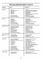
TROUBLE SHOOTING ..........................................
27-26
REPAIR PARTS-TRACTOR ..................................
36-53
SLOPE SHEET ...........................................
BACK PAGE
2
PRODUCT SPECIFICATIONS .....................................
3
CUSTOMER RESPONSIBILITIES ....................... 3,15-16
WARRANTY ..................................................................
3
TABLE OF CONTENTS ................................................
4
INDEX ...........................................................................
4
ASSEMBLY ...........................................................
7-10
nNDEX
A
Adjustment,Attachment
Lift Spring, 23
Adjustments:
Brake .....................................
21
Carburetor ............................... 25
Clutch Pulley ........................... 21
Gauge Wheels ....................... 13
Mower:
Front-To-Back ................... 20
Side-To-Side .................... 19
Mower Drive Belt ..................... 20
Throttle Control Cable ............. 25
Air Filter, Engine .........................
18
Air, Screen, Engine ....................... 18
Assembly .................................
7-10
Attachment Lift Spring:
Adjustment ............................. 23
B
Battery:
Charging ..................................
8
Cleaning ...............................
17
Installation .............................. 10
Levels ..................................
8,17
Preperation ................................ 8
Starting with Weak Battery ...... 23
Storage ..................................
26
Terminals ................................ 17
Belt:
Motion Drive:
Removal/Replacement
....... 22
Mower Blade Drive:
Removal/Replacement
....... 2 t
Mower Drive:
Removal/Replacement
....... 20
Blade:
Replacement ........................... 16
Sharpening .............................. 16
Brake Adjustment .......................... 21
C
Carburetor, Adjustment .................. 25
Controls, Tractor ............................ 11
Customer Responsibilities ........ 15-16
Engine:
Air Filter .............................. 18
Foam Pre-Cleaner ............ 16
Air Screen, Engine ............... 18
Cooling Fins, Engine ............ 16
Engine Oil ............................ 17
Fuel Filter. ........................... 18
Spark Plugs ......................... 16
Tractor:
Battery ................................
t7
Blade .................................... 16
Lubrication Chart ................ 15
Maintenance Schedule ......... 16
Tire Care ..................... 6,16,22
Transaxle Oil Level .............. 16
Cutting Height, Mower .................. 12
29
E
Engine:
Adjustments:
Carburetor .......................... 25
Throttle Contr_ Ca6!e ......... 25
Air Filter ........... __. ,.. _............ 18
Air Screen ....... ..._ ...J ........... 18
Cooling Fins ..... \ .../ ........... 18
Oil
.......
\/ ............
17
Oil Change
Level ...........................
13,17
Oil Type ...........
A ............. 17
Preparation ......... /,-_ ........... 13
Starting .............................
14
Storage .............. /__._ .......... 26
F
Filter':
Air' Cleaner. ....................... ,_,,, 18
Fuel ................................... ,.\., 18
OIL .....................................
Z18
Fuel:
Storage ...................................
26
Type ........................................ 14
Fuse ...............................................
23
H
Headlights ......................................
Hood Removal ..............................
23
24
L
Leveling Mower Deck ............... 19-20
Lubrication Chart ........................... 15
M
Maintenance Schedule ..................
Mower:
Adjustment:
Front-To-Back ................
Side-To-Side ....................
Blade Replacement .................
Blade Sharpening ....................
Cutting Height ........................
Installation ...............................
Operation ................................
4
O
Oil:
D
Decals ..........................................
Removal .................................. 19
Mowing Tips ................................
14
Muffler ............................................
18
Spark Arrester ........................ 3
15
20
19
16
16
12
9
13
Cold Weather Conditions ... 13,17
Engine ....................................
t7
Transaxle ............................... 16
Operating Mower ........................... t 3
Operation ................................
11-14
P
Parking Brake .........................
11,12
Parts Bag .....................................
6
Product Specifications .................... 3
S
Safety Rules ...................................
2
Schematic .....................................
54
Seat .............................................
8
Service & Adjustments ............. 19-25
Attachment Lift Spring .......... 23
Clutch Pulley ........................... 21
Fuse ....................................
23
Mower Adjustment
Front-To-Back ................... 20
Side-To-Side .................... 19
Motion Drive Belt:
Removal/Replacement ...... 22
Mower Blade Drive Belt:
Removal/Replacement ...... 21
Mower Drive Belt:
Removal/Replacement ...... 20
Mower Removal ...................... 19
Tire Care ......................
8,16,22
Slope Guide Sheet ........................ 55
Spark Plugs ................................
18
Specifications ................................. 3
Starting the Engine ...................... 14
Steering Wheel .......................... 7,22
Stopping the Tractor ..................
12
Storage .......................................... 26
T
Throttle Control Cable:
Adjustment .............................. 25
Tires ......................................
8,16,22
Troubleshooting ........................ 27-28
W
Wheels .........................................
Wiring Schematic .......................
29
54
I,,,I,,
H,II
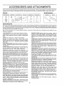
ACCESSORIES
AND ATTACH
i
ii
ENTS
i,i
These accessories and attachments were available when the unit was purchased They are also available at most Sears retail outlets,
catalog and service centers Most Sears stores can order these items for you when you provide the model number of your tractor
MAINTENANCE
ENGINE
SPARK PLUG
MUFFLER
AIR FILTER
GAB CAN
ENGINE OIL
STABILIZi
BLADES
BELTS
PERFORMANCE
Sears offers a wide vadety of attachments that fit your vehicle Many of these are listed below with brief explanations of how they can help
you This fist was current at the time of publication; however, it may change in future years - more attachments may be added, changes may
be made in these attachments, or some may no longer be available or fit your model Contact your nearest Sears stere for the accessories
and attachments that are available for your unit.
Most of these attachments
attaching and detaching
do not require additional hitches or conversion
LAWN SWEEPERS let you collect grass clippings and leaves
LAWN VACS for powerful collection of heaw grass clippings and
leaves
Wand attachment to pick up debris in hard-to-reach
places
CARTS make hauling easy Variety of sizes available.
ROLLER for smoother lawn surface.
36-inch wide, 18-inch
diameterwater-tightdrumholdsupto390{bs
ofweight Rounded
edges prevent harm to turf
Adjustable scraper automatically
cleans drum
SPREADER/SEEDERS
make seeding, fertilizing, and weed killing easy Broadcast spreaders are also useful for granular deicers and sand
CORING AERATOR takes small plugs out of soil to allow moisture and nutrients to reach grass roots
36-inch swath
24
hardened steel coring tips 150 Ib capacity weight tray
AERATOR promotes deep root growth for a healthy lawn Tapered 2 5-inch steel spikes mounted on 10-inch diameter discs
puncture holes in soil at close intervals to let moisture soak in
MULCH RAKE/DETHATCHER
loosens soil and flips thatch and
matted leaves to lawn surface for easy pickup Twenty spring ttne
teeth Usefultapreparebareareasforseeding
Availableforfront
or rear mounting
SPRAYERS use 12-volt DC electric motor that connects to the
tractor battery or other 12-volt source.
Includes booms for
automatic spraying when pulling, and hand held wand for spot
spraying
Wand has adjustable spray pattern
For applying
herbicides, insecticides, fungicides, and liquid fertilizers
SNOWTHROWER has 40-inch swath Drum-type auger handles
powdery and wet!heavy snow
Mounts easily with simple pin
arrangement
Discharge chute adjusts from tractor seat 6Hnch
diameter spout discharges snow 10 to 50 feet Lift controlled at
tractor seat (Use with chains, wheel weights, or rear drawbar
weight )
TIRE CHAINS are heaw duty; closely spaced extra-large cross
links give smooth ride, outstanding traction
WHEEL WEIGHTS for rear wheels provide needed traction for
snow removal or dozing heavy materials
(55 Ibs each )
TRACTOR CAB has heavy duty vinyl fabric over tubular steel
frame, ABS plastic top; clear plastic windshield offers 360 degree
visibility Hinged metal doors with catch. Keeps operatorwarm
and dry Remove vinyl and windshields for use as sun protector
in summer
(Catalog only)
Optional accessories
for tractor cab: tinted/tempered solid
safety glass windshield with hand operated wiper; 12-volt amber
caution light for mounting on cab top (Catalog only )
kits (those that do are indicated) and are designed for easy
TRACTOR COVER protects tractor from weather
Made of
Evolution 3 fabric (water-repellent, extremely breathable, light
weight, soft, non-abrasive, pliable in all temperatures, durable,
stain/tear/puncture resistant, will not shrink or stretch) (Catalog
only)
TILLER has 8 hp engine to prepare seed beds, cultivate, and
compost garden residue Chain-drive transmission. Six 11-inch
diameter one piece heat-treated steel tines Tills 30_inch path
(Requires sleeve hitch )
TILLER has 5 hp engine and 36-inch swath to prepare seed beds,
cultivate, and compost garden residue. Tiller has Its own built-in
liftand depth control system and does NOT require a sleeve hitch
Fits any lawn, yard, or garden tractor
Simply hook up to the
tractor drawbar and go!
DOZER BLADE removes snow; grades dirt, sand and gravel. 48
inches wide, 17 inches high, clears 44-inch path when angled
Master lift control lever for operator ease Spring trip for snow
removal on uneven pavement; built-In float for blade to follow
ground contour Reversible, replaceable scraper bar (Use with
tire chains, wheel weights or rear drawbar weight )
FRONT END LOADER system includes double wide rear tires.
rear weight box, and hydraulically operated 526 cuff bucket
(Catalog only)
REAR BLADE is 42 inches wide and operated from driver's seat
Reversible steel blade can be angled at 30 degrees for grading
Reverses for snow plowing (Requires sleeve hitch )
SLEEVE CULTIVATOR is 43 inches wide Prepares ground for
seeding, helps weed control Steel frame holds 5 adjustable
sweeps Adjusts vertically, horizontally
(Requires sleeve hitch )
Optional accessory for cultivator: steel furrow opener for wider
openings for potatoes, corn, and other deep-seeded crops
PLOW turns soil 6 inches deep, cuts 10-inch furrow. Crank
adjustment controls depth, 3-position yoke sets width Heaw
steel landslide for straight furrowing
(Requires sleeve hitch )
DISC HAR ROW has 2 gangs of 4 steel blades that angle from 10
to 20 degrees, 40 inches wide
Can hook 2 units in tandem
(Requires sleeve hitch )
WEIGHT BRACKET for drawbar for snow removal applications
Can be mounted on front of tractor for plowing applications Uses
(1) 55 Ib weight
SLEEVE HITCH for use with master lift system
couples/uncouples
Single pin
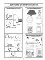
CONTENTS OF HARDWARE PACK
,,i
..................
i.i
Parts Bag contents
i,
H
, i
,H
.
,Ul
shown full size
i,.
Parts packed separately
.....
IN
ii
i
i....
luH
in carton
i,
Seat
Battery acid
I....
I
(1) Shoulder Bolt 5/16-18
(1) Knob
Steering Wheel
Battery
Parts Bag
Owner's Manual
(1) Washer 17/32 x 1-3/16 x 12 Ga.
rst bag contents
not shown
full size
(4) Retainer Springs
(4) Washers
11/32 x 1
V-Belt
(2) Hex Bolts 1/4- 20 x 3/4
@
_
(2) Battery Carriage Bolts 1/4-20 x74/2
'_
(2) Hex Nuts 1/4 - 20
Steering Wheel Insert
(2) Washers
i i
9/32 x 5/8 x 16 Ga. (2) Lock Washers
i,
i
,,,i,
1/4
.....
(2) Wing Nuts 1/4 - 20
15 = Slope Sheet
6
Battery Capsand Instructions
i,,,,.,
ii
i,,,,,
..i
i..,,
Hi,
ASSEM
TOOLS
REQUIRED
L¥
FOR ASSEMBLY
A socket wrench set will make assembly easier. Standard
wrench sizes are listed.
(2) 7/16" wrenches
(1) Tire pressure gauge
(1) Adjustable wrench
(1) Utility knife
,_J_.
_/
UNPACK
ATTACH
LOCK
WASHER_
r'.'_
_
WHEEL
STEERING -ADAPTER
G
HEX BOLT
FLAT WASHER
UNIT FROM CARTON
CARTON
Remove all accessible loose parts from carton (See
page 6)
Cut along dotted lines on the carton, from top to bottom,
all four corners of carton and lay panels flat
Remove mower deck from skid.
Check for any additional loose parts or cartons and
remove
BEFORE
STEERING
WHEEL
INSERT
--
When right and [eft hand is mentioned in this manual, it
means when you are in the operating position (seated
behind the steering wheel)
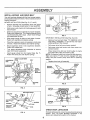
TO REMOVE
_
ROLLING
STEERING
STEERING
UNIT OFF SKID
WHEEL
/
(See Fig. 1)
J
•
Remove hex bolt, lock washer and large flat washer
from steering shaft.
Position front wheels of the tractor so they are pointing
straight forward.
Position steering wheel so cross bars are horizontal
(left to right) andslide onto adapter.
Secure steering wheel to steering shaft with hex bolt,
lock washer and large flat washer previously removed.
Tighten securely.
Snap insert into center of steering wheel.
Remove protective plastic from tractor hood and grill
l_ "3r
I,"
)
\
,
/
///
t_
FIG, 1
LIFT[.EVER
CLUTCH/BRAKE
PEDAL
IMPORTANT:
CHECK FOR AND REMOVE ANY STAPLES
IN SKID THAT MAY PUNCTURE
TIRES WHERE UNIT IS
TO ROLL OFF SKID,
(See Fig, 2)
Raise attachment lift lever to its highest position,
Place gearshift lever in "NEUTRAL" position.
Release parking brake by depressing clutch/brake
pedal
Rol! unit backwards off skid,
GEARSHIFT
LEVER
FIG, 2
7
SHAFT
u.i
,i
ASSEMBLY
HOW TO SET UP YOUR TRACTOR
INSTALL
PREPARE
Adjust seat before tightening adjustment knob.
BATTERY
CAUTION:
(See Fig. 3)
SEAT
(See
Fig. 4)
Remove cardboard packing on seat pan.
Wear eye and face shield.
Place seat on pan and assemble shoulder boil
Wash hands or clothing immediately if
accidentally in contact with battery acid.
Assemble adjustment knob and flat washer loosely.
Do not tighten.
Do not smoke. Fumes from charged bat,.
tery acid are explosive.
Tighten shoulder bolt securely.
Lower seat into operating position and sit on seat
Read the instructions included with the
battery vent caps, Always wear gloves,
clothing and goggles to protectyour hands,
skin and eyes.
Slide seat until a comfortable position is reached which
allows you to press clutch/brake pedal all the way
down.
Get off seat without moving its adjusted position.
Your unit has a battery charging system which is sufficient
for normal use_ However, periodic charging of the battery
with an automotive charger' will extend its life.
See instructions packed with vent caps in parts bag.
Fill battery with acid_ Fill each celt until it reaches the
bottom of the vent wells_ Do not overfill.
Allow battery to stand and settle for at least thirty
minutes, After standing, check the level of acid. If
below the vent wells, add more acid until the correct
level is reached.
Raise seat and tighten adjustment knob securely.
SEATPANx
SHOULDER
While battery is standing (after adding acid) and later, while
batter,! is being charged, continue with assembly of unit.
IMPORTANT:
TO MAXIMIZE THE LIFE OF YOUR
BATTERY, IT IS NECESSARY THAT THE BATTERY BE
CHARGED BEFORE USE
FAILURE TO CHARGE
BATTERY CAN RESULT IN A SHORTENED BATTERY
LIFE
Charge battery at a rate of 6 amperes for 1 hour. Use
a 12 volt battery charger. Observe all safety precautions required for battery charging.
CI'_CK TIRE PRESSURE
Reduce tire pressure to PSI shown in "PRODUCT
SPECIFICATIONS" on page 3 of this manual.
Follow instructions on how to install battery.
..............
'
:_
_U_
_/,.Z_
T/VENT
_
CAP
WELL
'_BATtERY
r_
zl_
__
r_21.,
FLAT WASHER
The tires on your unit were overinflated at the factory for
shipping purposes. Correct tire pressure is important for
best cutting performance.
Dispose of excess battery acid. Neutralize acid for
disposal by adding it to four inches of water in a five
gallon plastic container. Stir with a wooden or plastic
paddle while adding baking soda until the addition of
more soda causes no more foaming.
"
\\ \
FIG. 4
Check battery case for leakage to make sure that no
damage has occurred in handling.
['
\ \
fADJUSTMENT
KNOB
Install the vent caps to cover the vent wells. Wash the
top of the battery with water to remove any acid, then
wipe dry.
//VENT
_ \_
//_'_'__
Check the acid level after the battery is charged. If the
acid has fallen below the correct level, add distilled or
iron free water.
CUT AWAY VIEW
X
SE/T_
CELL ACID
LEVEL
FIG. 3
8
ASSEMBLY
INSTALL
MOWER
AND
DRIVE
BELT
GAUGE
WHEEL
Your unit has been shipped with the front mower suspension bracket banded to the frame, Remove bands and pivot
bracket downward
MOWER INSTALLATION
(See Figs 5, 6, 7 and 8)
BAR
_/
Remove banding from suspension arms and gauge
wheels Set gauge wheels aside for later assembly
'oo
L.)_
Slide front suspension brackets into mower bracketsr
Retain with release pins, Turn height adjustment knob
counterclockwise until it stops Lower mower linkage
with attachment lift lever,
DRIVE BELT INSTALLATION
Roll mower drive belt over primary mandrel
Roll mower drive belt forward over front mower suspension bracket
Place suspension arms in rear suspension brackets
Retain with release pins
to remove
Place mower drive belt over clutch pulley on engine
and under idler pulley and tension pulley
NOTE: Pulltension pulley lever forward for belt clearance
Make sure narrow "V" side of belt is engaged with each
pulley, and push tension pulley lever back to opearting
position
Insert gauge wheel bar into bracket (See Fig 7),
Retain with clevis pins and retainer springs,
DEPTH
KNOB
(See Figs 8 and 9)
Remove hood and grill (See "TO REMOVE HOOD
AND GRILL ASSEMBLY" in the Service and Adjustments sections of this manual),
Place the suspension arms on brackets on both sides
of frame, Retain with washers and retainer springs
SUSPENSION
ARM
CLEVIS
PIN
FIG. 7
Slide studs through lift links on both sides of tractor
Retain with washers and retainer springs
Turn height adjustment knob clockwise
slack from mower suspension
BRA
;==;
Slide mower under tractor with discharge guard to right
side of tractor
ADJUSTMENT
BELT
Replace hood and grill assembly
MOWER
DRIVE
PRIMARY
BRACKETS
FRONT
SION
BRACKET
RI
PIN
RELEASE
PIN
FIG. 8
FIG, 5
_
MOWER
RIVE
RETAINER SPRING
BRACKET
BELT
IDLER
C
PULLEY
SUSPENSION
ARM
TENSION/
- WASHER
_"_,'
PULLEY
.IFT LINK
RETAINER
FIG, 9
CHECK
FIG, 6
DECK
LEVELNESS
For best cutting,results, mower housing should be properly
leveled,
See TO LEVEL MOWER HOUSING" in the
Service and Adjustments section of his manual
9
CHECK
BELTS
FOR PROPER
POSITION
OF ALL
VENT
CAP _.
See the figures that are shown for replacing motion, mower
drive, and mower blade drive belts in the Service and
Adjustments section of this manual Verify that the belts are
routed correctly
CHECK
BRAKE
SYSTEM
BATTERY
,EY
HOLE
BEFORE YOU OPERATE AND ENJOY YOUR NEW
TRACTOR, WE WISH TO ASSURE THAT YOU RECEIVE
THE BESTPERFORMANCEAND
SATISFACTION FROM
THIS QUALITY PRODUCT
PLEASE REVIEW THE FOLLOWING
Place battery in plastic tray, battery terminals to front of
tractor
First connect RED battery cable to positive (+) battery
terminal with hex bolt, flat washer, lock washer and hex
nut as shown Tighten securely
Connect BLACK grounding cable to negative (-) battery
terminal with remaining hex bolt, flat washer, lock washer
and hex nut. Tighten securely.
All assembly instructions have been completed.
v"
No remaining loose parts in carton
v"
Battery is properly prepared and charged•
hour at 6 amps).
Seat is adjusted comfortably and tightened securely
t/
All tires are properly inflated (For shipping purposes,
the tires were over-inflated at the factory).
Use terminal access doors for:
Inspection for secure connections (to tighten hardware).
,/
Engine oil is at proper level
_"
Fuel tank is filled with fresh, c_ean, regular unleaded
gasoline
Become familiar with all controls-their location and
function Operate them before you start the engine
Inspection for corrosion.
,/
Testing battery.
Jumping (if required).
1/
Periodic charging.
POSITIVE
.(RED)
,:/____/,'J"_/CABLE
_::?,.';_
CABLE
_
_v
I"_-_
_
[_
_
_.._._
/
FLAT
WASHER
BOLT
_ /
"
,r_
FIG. 10
Check mower and drive belts. Be sure they are routed
WHILE LEARNING HOW TO USE YOUR TRACTOR, PAY
EXTRA ATTENTION TO THE FOLLOWING IMPORTANT
ITEMS:
Be sure terminal access doors are closed.
;,.
Be sure mower deck is properly leveled side-to-side/
front-to-rear for best cutting results (Tires must be
properly inflated for leveling).
_l_._erly around pulleys and inside all belt keepers
,/
Che#k wiring See that all connections are still secure
and wires are properly clamped=
Tighten wing nuts by hand making sure battery bolts
remain in slots of the key holes in the battery supporL
-..,:,_.:_._:.- .......
(Minimum 1
,,/
Y
Position terminal guard over the battery as shown, lower
bolts into key holes and slide square shafts of bolts into
slots of key holes
CHECKLIST:
v"
,/
Slide the two battery bolts through the terminal guard
and start the wing nuts onto the threads
(BLACK)_/',._,
BATTERY
_-*'_'--DRAIN
TUBE
/ CHECKLIST
Make sure drain tube is fastened to drain hole in battery
tray and battery tray is positioned in hole of battery
support
NEGATIVE
{ _ACCESS
I
"DOORS
FIG. 11
Raise hood.
S
WING NUTS
(See Figs. 10 and 11)
bracelets, wristwatch bands, rings, etc.
Positive terminal must be connected first
to prevent sparking
from accidental
grounding.
HEX NUT
._
j
CAUTION: Do not short battery terminals.
efore Installing
battery, remove metal
_
---_ -,..
""
..,'"
AL
After you learn how to operate your tractor, check to see
that the brake is properly adjusted. See "TO ADJUST
BRAKE" in the Service and Adjustments section of this
manual
INSTALL
.
10
Be sure brake system is in safe operating condition.
i,=,,
,
ii
,
OPERATION
KNOW YOUR TRACTOR
READ THIS OWNER'S
MANUAL
AND SAFETY
RULES
BEFORE
OPERATING
YOUR
TRACTOR.
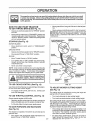
Compare the illustrations with your Tractor to familiarize yourself with the location of various controls and adjustments. Save
this manual for future reference.
A'rrACHMENT
CLUTCH
SWITCH,
LEVER
AMMETER
CLUTCH/BRAKE
PEDAL
IGNITION SWITCH
CHOKE CONTROL
PARKING
BRAKE
HEIGHT ADJUSTMENT
KNOB
GEARSHIFT
LEVER
RANGE SHIFT LEVER
FIG, 12
Sears tractors conform to the safety standards of the American National Standards Institute
ATTACHMENT
CLUTCH SWITCH - Used to engage
mower blades or other attachments mounted to your tractor.
LIFT LEVER- Usedto raise and lower mower deck or other
attachments mounted to your tracton
CLUTCH/BRAKE
PEDAL - Used for declutching and
braking the tractor and starting the engine.
GEARSHIFT LEVER - Selects the speed and direction of
tractor.
THROTTLE CONTROL - Used to control engine speed,
RANGE SHIFT LEVER - Allows "HI" or "LO" speed for all
forward and reverse gears,
IGNITION SWITCH - Used to start and stop the engine,
AMMETER - Indicates battery charging (+) or discharging
(-).
LIGHT SWITCH - Turns the headlights on and off,
PARKING BRAKE LEVER - Locks clutch/brake pedal into
the brake position.
CHOKE CONTROL - Used when starting a cold engine
HEIGHT ADJUSTMENT KNOB- Used to adjustthe mower
height
11
OPERATION
The operation of any tractor can result in foreign objects thrown into the eyes, which can result
in severe eye damage, Always wear safety glasses or eye shields before starting your tractor
and while moving, We recommend Wide Vision Safety Mask for over the spectacles or standard
safety glasses,
Move gearshift and range shift levers to desired position,
HOW TO USE YOUR TRACTOR
TO SET PARKING
BRAKE
(See Fig. 13)
Depress clutch/brake pedal into full "BRAKE" position
and hold
Place parking brake lever in "ENGAGED" postion and
releasepressurefromclutch/brakepedal
Pedalshould
remain in "BRAKE" position Make sure parking brake
will hold vehicle secure
STOPPING
(See
Fig.
Slowly release clutch/brake pedal to start movement
IMPORTANT:
BRING TRACTOR TO A COMPLETE STOP
BEFORE SHIFTING
OR CHANGING
GEARS,
FAILURE
TO 130 SO WILL SHORTEN THE USEFUL LIFE OF YOUR
TRANSAXLE
"DRIVE"
POSITION
CLUTCH/BRAKE PEGAL
"BRAKE" POSITION
13)
MOWER BLADES
Move a_achment
position
GROUND DRIVE -
clutch switch to "DISENGAGED"
AI-rACHMENT
CLUTCH SWITCH
Depress clutch/brake pedal into full "BRAKE" position.
Move gearshift lever to "NEUTRAL" position,
ENGINE -
CHOKE
CONTROL
Move Throttle Control to "SLOW" position,
Turn ignition key to "OFF" position and remove key.
Always remove key when leaving vehicle to prevent
unauthorized use,
THROTTLE
IGNITION
LEVER
Never use choke to stop engine
NOTE: Under certain conditions when unit is standing idle
with the engine running, hot engine exhaust gasses may
cause "browning" of grass. To eliminate this possibility,
always stop engine whBn stopping unit on grass areas.
I
._
_,
described
above, before leaving the
operator's
position;to
empty grass catcher,
CAUTION; Alwaysstopunitcompletely,
as
etc.
TO USE CHOKE
CONTROL
To engage choke control, pull knob out. Slowly push
knob into disengage,
TO USE
THROTTLE
CONTROL
(See
Operating engine at less than full throttle reduces the
battery charging rate and the engine cooling air flow,
Full throttle offers the best mower performance_
FORWARD
AND
BACKWARD
Fig. 13)
The direction and speed of movement is controlled by the
gearshift lever,
Start tractor with clutch/brake pedal depressed and
gearshift lever in "NEUTRAL" position.
RANGE
SHIFT
LEVER
FIG. 13
TO ADJUST
MOWER
CUTTING
HEIGHT
(See Fig. 13)
The cutting height is controlled by turning the height adjustment knob in desired direction.
Fig. 13)
Always operate engine at full throttle
TO MOVE
GEARSHIFT
LEVER
(See Fig, 13)
Use choke control whenever you are starting a cold engine,
Do not use to start a warm engine,
(See
HEIGHT
ADJUSTMENT
KNOB
Turn knob clockwise to raise cutting height.
*
Turn knob counterclockwise
to lower cutting heighL
The cutting height range is approximately 1-1/4" to 3-3/4".
The heights are measured from the ground to the blade tip
with the engine not running. These heights are approximate and may vary depending upon soil conditions, height
of grass and types of grass being mowed.
The average lawn should be cut approximately 2-1/2
inches during the cool season and over 3 inches during
hot months. For healthier and better looking lawns,
mow often and after moderate growth
For best cutting performance, grass over 6 inches in
height should be mowed twice. Make the first cut
relatively hinh' the, =e_nnrt fn rl cit 4 h ;_ ,
OPERATQON
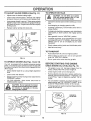
TO ADJUST
GAUGE
WHEELS
TO OPERATE
(See Fig. 14 )
ON HILLS
i,
o
Adjust mower to desired cutting heighL
Lower mower with lift control, Remove rear retainer
spring and clevis pin which secure each gauge wheel
_
_
CAU=rlON_
Do
i
not
drive
=
up
or
down
hills with slopes greater than 15 ° and
do not drive across any slope.
Lower gauge wheels to ground. Raise gauge wheels
slightly to align holes in bracket and gauge wheel bar
and insert clevis pins. Gauge wheels should be slightly
off the ground.
Choose the slowest speed before starting up or down
hills_
Avoid stopping or changing speed on hills.
If slowing is necessary, move throttle control lever to
slower position.
Replace retainer springs into clevis pins
If stopping is absolutely necessary push clutch/brake
pedal quickly to brake position and engage parking
brake.
RETAINER
GAUGE
WHEEL
BAR
Move gearshift
lever to "NEUTRAL"
position.
To restart movement, move gearshift lever to 1st gear
and range shift lever to "LO" position_ Be sure you have
allowed room for unit to roll slightly as you restart
movement
GAUGE
WHEEL
Slowly release parking brake and clutch/brake
pedal
Make all turns slowly
TO TRANSPORT
3LEVIS
PINS
Raise attachment lift control to highest position
When pushing or towing your unit, be sure gearshift
lever is in "NEUTRAL" position,
FIG. 14
Do not push unit at more than five (5) MPH.
TO OPERATE
MOWER
(See
Figs.
12 and
13)
BEFORE
Your unit is equipped with an operator presence sensing
switch Any attempt by the operator to leave the seat with
the engine running and the mower clutch engaged will shut
off the engine
CHECK
OIL LEVEL
(See Fig. 16)
Check engine oil with unit on level ground.
Remove dipstick and wipe clean, replace, wait for a few
seconds, remove and read oil level. If necessary, add
oil until "FULL" mark on dipstick is reached. Do not
overfill
Lower mower with lift lever,
Engage mower by slowly moving mower clutch lever to
"ENGAGED" position,
TO STOP MOWER - Move mower clutch lever to
"DISENGAGED" position.
&
ENGINE
THE ENGINE
The engine in your unit has been shipped, from the
factory, already filled with summer weight oil.
Select desired height of cut, using height adjustment
knob,
' ,_
STARTING
For cold weather operation you should change oi! for
easier starting (see "OIL VISCOSITY CHART" in the
Customer Responsibilities section of this manual)
To change engine oil, see the Customer Responsibilities
section in this manual,
without either the entire grass catcher,
on
mowers Do
so not
equipped,
dis.
CAUTION;
operate or
the the
mower
charge guard in place.
_
ENGINE OIL
FILLER CAP
D,PST,
DISCHARGE
GUARD
FIG. !6
FIG. 15
13
OP£RATION
MOWING
ADD GASOLINE
Fill fuel tank. Use fresh, clean, regular unleaded
gasoline. (Use of leaded gasoline will increase carbon
and lead oxide deposits and reduce valve life).
iMPORTANT= WHEN OPERATING IN TEMPERATURES
BELOW 32°F(0°C), USE FRESH, CLEAN WINTER GRADE
GASOLINE TO HELP iNSURE GOOD COLD WEATHER
STARTING
wARNING:
Experience indicates that alcohol blended
fuels (called gasohol or using ethanol or methanol) can
attract moisture which leads to separation and formation of
acids during storage. Acidic gas can damage the fuel
system of an engine while in storage. To avoid engine
problems, the fuel system should be emptied before storage of 30 days Or' longer, Drain the gas tank, start the
engine and let it run until the fuel lines and carburetor are
empty. Use fresh fuel next season. See Storage Instructions for additional information.
Never use engine or
carburetor cleaner products in the fuel tank or permanent
damage may occur.
CAUTION:
Fill to bottom of gas tank
filler neck. Do not overfill. Wipe off any
spilled oil or fuel Do not store, spill or
use gasoline near an open flame.
.,.n
TO START
ENGINE
,,,,,.
Tire chains cannot be used when the mower housing
is attached to unit.
Mower should be p,,roperly leveled for best mowin_
perfom_anca. See TO LEVEL MOWER HOUSING
m the Service and Adjustments
section of this
manual.
Use the runner on the right hand side of mower as
a guide. The blade cuts apprximately an inch outside the runner (See Fig. 15).
The left hand side of mower should be used for trimming.
Drive so that clippings are discharged onto the area
that has been cut. Have the cut area to the right of
the machine. This will result in a more even distribution of clippings and more uniform cutting.
When mowing large areas, start by turning to the
right so that clippings will discharge away from
shrubs, fences, driveways, etc. After one or two
rounds, mow in the opposite direction making left
hand turns urttil finished (See Fig. 17).
I
If grass is extremely tall, it should be mowed twice
to reduce load and possible fire hazard from dried
clipping& Make first cut relatively high; the second
to the desired height
Do not mow grass when it is weL
plug mower and leave undesirable
grass to dry before mowing.
(See Fig.13)
When starting engine for the first time or if engine has
run out of fuel, it will take extra cranking time to move
fuel from the tank to the engine.
Depress the clutch/brake
brake.
Move attachment
position.
clutch to "DISENGAGED"
position.
When operating attachments, select a ground speed
that will suit the terrain and give best performance of
_he attachment being used.
Pull choke control out to "CHOKE" position for cold
engine start.
For warm engine start do not use
choke control.
Move throttle control to midway between "FAST" and
"SLOW" positions.
Turn ignition key clockwise to "START" position and
release key as soon as engine starts. Do net run
starter continuously for more than fifteen seconds
per minute.
If engine does not start after several
attempts, move throttle control to "FAST" position,
wait a few minutes and try again.
When engine starts, slowly push choke control in.
Move throttle control to "FAST" position,
Allow engine to warm up for a few minutes before
engaging clutch/brake pedal or attachment clutch
switch,
FIG. 17
NOTE: If at a high altitude (above 3000 feet) or in cold
temperatures (below 32 ° P), the carburetor fuel mixture
may need to be adjusted for best engine performance.
See "TO ADJUST CARBURETOR" in the Service and
Adjustments section of this manual.
" "A
_
""cAUTION:
Beiore driving the tract'or
install mower or remove front mower
suspension bracket and suspension
arms.
,,,,
Wet grass will
clumps. Allow
Always operate engine at full throttle when mowing
to assure better mowing performance and proper
discharge of material,
Regulate ground speed by
selecting a low enough gear to give the mower' cutting performance as well as the quality of cut desired.
pedal and set the parking
Place gearshift lever in "NEUTRAL"
TIPS
14
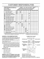
CUSTOMER RESPONSBBULmES
FILL IN DATES
AS YOU COMPLETE
REGULAR SERVICE
Check Brake Operation
Check Tire Pressure
T
Check for Loose Fasteners
R
Sharpen/Replace
A
Lubrication Chart
T
Check Battery Leve!/Recharge
0
Clean Battery and Terminals
R
Check Transmission
I
iv',
Mower Blades
J
Cooling
Adjust Blade Belt(s) Tension
Adjust Motion Drive Belt(s) Tension
Check Engine Oil Level
IQ/
v'
Change Engine Oil
E
Clean Air Filter
N
Clean Air Screen
G
Inspect Muffler/SparkArrester
v'
Replace Oil Filter (ff equipped)
N
_f,2
clean Engine Cooling Fins
Replace Spark Plug
_2
....
v'J
v's
Replace Air Filter Paper Cartridge
Replace Fuel Filter
1 - Changemoreoftenwhen operatingunderaheaW loador inhigh ambienttemperatures
2 - Servicemoreoftenwhen operating in dirty ol dusty condgiens
3 - Ifequippedwgheli filter,changeoltevery50 hours
4 * Replace bfadesmoreeftenwhen mowing In sandy setl
GENERAL RECOEvlMENDATIONS
LUBRICATION
The warranty on this vehicle does not cover items that
have been subjected to operator abuse or negligence, To
receive full value from the warranty, operator must maintain unit as instructed in this manuaL,
(_) TIE ROD BALL JOINTS
@
_[---
/
Some adjustments will need to be made periodically to
properly maintain your unit
All adjustments in the Service and Adjustments section of
this manual should be checked at least once each season.
BEAR,NG
ZERK
(_) STEERING
SECTOR GEAR
pLATE
Once a year you should replace the spark plug, clean
or replace air filter, and check blades and belts for
wear. A new spark plug and clean air filter assure
proper air-fuel mixture and help your engine run better
and last longer,
BEFORE
CHART
EACH USE
SPINDLE
ZERK
@
\ll
_.__"°"_:'::_'"_
VI. i BEARING
ZEaK
,t,;:;"
t:::::::::::::,
I L_
_'-
ENGINE (_)
(_) CHECI{JADD-.
TRANSAXLE
FLUID
Check engine oil level.
_';:
._ : L
:: "-i"
Check brake operation_
Check tire pressure.
Check for loose fasteners.
IMPORTANT: DO NOT OIL OR GREASE THE PIVOT POINTS
WHICH HAVE SPECIAL NYLON BEARINGS VISCOUS LUBRICANTS WILL ATTRACT DUST AND DIRT THAT WILL SHORTEN
THE LIFE OF THE SELF-LUBRICATING BEARINGS. IF YOU
FEEL THEY MUST BE LUBRICATED, USE ONLY A DRY, POWDERED GRAPHITE qYPE LUBRICANT SPARINGLY
SAE 30 MOTOR OIL API - SG
(_) GENERAL
PURPOSE GREASE
(_) REFER TO ENGINE MAINTENANCE
15
SPRAY SILICONE
LUBRICANT
SECTION
(MOVE BOOTS TO LUBRICATE)
CUSTOM
RESPONSIBULmES
TRACTOR
TO SHARPEN
BLADE
(See Fig, 19)
Care should be taken to keep the blade balanced. An
unbalanced blade will cause excessive vibration and eventual damage to mower and engine,
Always observe safety rules when performing any maintenance
BRAKE
OPERATION
The blade can be sharpened with afile or on a grinding
wheel Do not attempt to sharpen while on the mower.
If unit requires more than six (6) feet stopping distance at
high speed in highest gear, !han brake must be adjusted,
(See "TO ADJUST BRAKE' in Service and Ad ustments
section of this manua )
To check blade balance, drive a nail into a beam or waE
Leave about one inch of the straight nail exposed.
Place center hole of blade over the head of the nail, If
blade is balanced, it should remain in a horizontal
position, If either end of the blade moves downward.
sharpen the heavy end until the blade is balanced,
TIRES
Maintain proper air pressure in all tires (See "PRODUCT SPECIFICATIONS" on page 3 of this manual)
NOTE: Do not use a nail for balancing blade The lobes of
the center hole may appear to be centered, but are not,
Keep tires free of gasoline, oil, or insect control chemicals which can harm rubber_
Avoid stumps, stones, deep ruts, sharp objects and
other hazards that may cause tire damage.
BLADE
CENTER
HOLE
CARE
BLADE
For best results mower blades must be kept sharp, The
blades can be sharpened with a file or on agrinding wheel.
We suggest they be sharpened or' replacedafter every 25
hours of mowing, Check blades more often if mowing in
sandy conditions.
Do not attempt to sharpen blades while they are on the
mower_
Replace bent or damaged blades.
FIG. 19
BLADE
REMOVAL
(See Fig. 18)
Raise mower to highest position to allow access to
blades.
CHECK
OIL LEVEL
(See Fig. 20)
Block up rear axle securely or use a tractor jack,
Remove hex bolt, lock washer and flat washer securing
blade_
Install new or resharpened
towards deck as shown.
TRANSAXLE
Remove left rear wheel by removing hub bolts.
blade with trailing edge up
Remove filler plug from transaxla. Oil level must be
even with plug threads. If necessary, fill with SAE 30
non-detergent oil (ISO 100). Replace filler plug,
Reassemble hex bolt, lock washer and flat washer in
exact order as shown.
Tighten bolt securely (30-35 Ft. Lbs, torque),
IMPORTANT: BLADE BOLT IS GRADE 5 HEAT TREATED,
.B_eassemble wheel to hub,
For approximate capacity see "Product Specifications"
on page 3 of this manual
BLADE
MANDREL
_SSEMDLY
O
TRANSAXLE
OO
WASHE
0
LOCK WASHER
©
_E×BOLT
(GRADE5)*
*A GRADE S HEAT TREATED BOLT
CAN BE IDENTIFIED
BYTHREE
LINES ON THE BOLT HEAD AS
SHOWN AT LEFT,
FIG. 20
FIG. 18
16
FILLER PLUG
,,
,,,
=,,
,,,
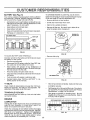
CUSTOMER RF=.SPON BIL T E$
TO CHANGE ENGINE OIL (See Figs, 22, 23 and 24)
Determine temperature range expected before oil change
All oil must meet API service classification SG
• Be sure vehicle is on level surface.
BATTERY
(See Fig. 21)
Your unit has a battery charging system which is sufficient
for normal use. However, periodic charging of the battery
with an automotive charger will extend it's life_
Acid solution level in each battery cell should be even
with bottoms of vent wells, Add only distilled or iron free
water if necessary Do not overfill
Keep battery and terminals clean.
Keep battery bolts tight.
Keep vent caps tight and small vent holes in caps open.
• Oil will drain more freely when warm.
• Catch oil in a suitable container,
• Remove oil filler cap. Be careful not to allow dirt to
enter the engine when changing oil,
Recharge at 6 amperes for 1 hour,
ENGINE OIL
FILLER CAP
CUT AWAY VIEW
VENT CAP
VENT
I
WELL
LEVEL
DIPSTICK
F
FIG. 21
FIG. 22
TO CLEAN BATTERY AND TERMINALS
-
• Remove drain plug
Corrosion and dirt on the battery and terminals can cause
the battery to "leak" power,
Remove terminal guard
Disconnect BLACK battery cable first then RED battery cable and remove battery from tractor.
Wash battery with solution of four tablespoons of
baking soda to one gallon of water, Be careful not to get
the soda solution into the cells,
Rinse the battery with plain water and dry.
Clean terminals and battery cable ends with wire brush
until bright,
Coat terminals with grease or petroleum jelly,
Reinstall battery (See "INSTALL BATTERY" in Assembly section of this manual).
OIL DRAIN PLUG
FIG, 23
V- BELTS
After oil has drained completely, replace oil drain plug
Check V-Belts for deterioration and wear after 100 hours.
Replace if necessary, The belts are not adjustable. Replace belts if they begin to slip from wear
and tighten securely,
TRANSAXLE
Refill engine with oil through oil filler tube. Pour slowly,
Do not overfill, For approximate capacity see "Product
Specifications" on page 3 of this manual,
COOLING
Use gauge on dipstick for checking level Be sure
dip.stick is in all the way for accurate reading. Keep oil
at FULL _ine on dipstick,
Keep transaxle free from build-up of dirt and chaff which
can restrict cooling,
ENGINE
RECOMMENDED
LUBRICATION
Change the oil after the first two hours of operation and
every 50 hours thereafter or at least once a year if the
tractor is not used for 50 hours in one year,
Check the crankcase oil level before starting the engine
and after each eight (8) hours of continuous use. Add SAE
30W motor oil or equalivent, Tighten oil fill cap/dipstick
securely each time you check the oil level SAE 5W-30
motor oil may be used to make starting easier in areas
where temperature is consistently 32 ° F or lower.
oF .20 o
°C-29 °
0o
-18 °
SAE VISCOSITY
32 °
0°
FIG. 24
17
60 °
16°
GRADES
80 °
27 °
100 °
38 °
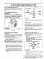
CUSTOMER RESPON
CLEAN
AIR SCREEN
(See Fig. 25)
Air screen must be kept free of dirt and chaff to prevent
engine damage from overheating. Clean with a wire brush
or compressed air to remove dirt and stubborn dried gum
fibers
CLEAN
ENGINE
COOLING
B L TME$
_.-_"_
WING NUT
ELEMENT
COVER
FINS
(See Fig. 25)
Remove any dust, dirt or oil from engine cooling fins to
prevent engine damage from overheating. Engine blower
housing must be removed. Remove sidepanels and hood
(See"TO REMOVE HOOD AND GRILLASSEMBLY" inthe
Service and Adjustments section of this manual.)
_Ad-k
AIR CLEANER
BASE "'_
FIG. 26
MUFFLER
Inspect and replace corroded muffler and spark arrester (if
equipped) as it could create a fire hazard and/or damage.
SPARK
PLUGS
Replace spark plugs at the beginning of each mowing
season or after every 100 hours of use, whichever comes
first. Spark plug type and gap setting is shown in "PRODUCT SPECIFICATIONS" on page 3 of this manual.
COOLING FINS
UNDER HOUSING
(BOTH SIDES)
ENGINE
AIR SCREEN
FIG. 25
AIR FILTER
FOAM
(See Fig. 26)
OIL FILTER
Replace the engine oil filter every season or every other oil
change if the tractor is used more than 100 hours in one
year
PRE-CLEANER
IN-LINE
FUEL FILTER
(See Fig. 27)
_,_omilter should be replaced once each season. If fuel filter
es clogged, obstructing fuel flow to carburetor, replacement is required.
Your engine will not run properly and may be damaged by
using a dirty air filter, Clean the foam pre-cleaner element
after every 25 hours of operation, more often if tractor j_.
used in very dusty, dirty conditions.
With engine cool, remove filter and plug fuel line
sections.
Place new fuel filter in position in fuel line with arrow
pointing towards carburetor',
Remove the wing nut and air cleaner cover.
Remove the element cover seal, element cover, paper
element, and pre.cleaner.
Be sure there are no fuel line leaks and clamps are
properly positioned.
NOTE: Do not attempt to clean or oil the paper cartridge.
Replace paper cartridge once a year or after every 100
hours of operation, more often if used in very dusty, dirty
conditions.
Immediately wipe up any spilled gasoline.
Wash foam pre-cleaner in liquid detergent and water.
Wrap foam pre-cleaner in cloth and squeeze dry.
Lightly coat foam pre-cleaner with clean engine oil
Squeeze in towel to remove excess oil. Do not saturate.
Install the paper element, pre-cleaner (cleaned and
oiled), element cover, and element cover seal.
Install the air cleaner cover and wing nut. Tighten wing
nut 1/2 to 1 full turn after nut contacts cover. Do not
over-tighten=
MP
CLAMFt_
___'_FUEL
FILTER
FIG. 27
CLEANING
Clean engine, battery, seat, finish, etc of all foreign
matter.
Keep finished surfaces and wheels free of all gasoline,
oil, etc=
Protect painted surfaces with automotive type wax.
18
We do not recommend using a garden hose to clean your
unit unless the electrical system, muffler, air filter and
carburetor are covered to keep water out. Water in engine
can result in a shortened engine life.
SERVICE AND ADJUSTMENTS
i
CAUTION:
i
BEFORE PERFORMING
,
ii
i
.....
i,r
i
ii
.....
ir
,i
i
i
ANY SERVICE OR ADJUSTMENTS:
Depress clutch/brake pedal fully and set parking brake,
Place gearshift lever in ' NEIJTRAL" position.
Place attachment clutch in "DISENGAGED"
position.
plug,
TRACTOR
SIDE.TO-SIDE
TO REMOVE
MOWER
o;oM
IMPORTANT: IFAN ATFACHMENT OTHERTHAN'FHE MOWER
DECK ISTO BE MOUNTED ON THE TRACTOR, REMOVETHE
LH. AND RH. SUSPENSION
ARMS AND THE FRONT
SUSPENSION BRACKET
DEPTH
KNOB
(See Figs, 29 and 30)
Raise mower to its highest position,
(See Fig. 28)
Place attachment clutch in "DISENGAGED" position
Turn height adjustment knob to lowest setting.
Move attachment lift lever forward to lower mower to its
lowest position.
Pull the four (4) release pinsout of suspension brackets
Pull back attachment lift lever and lock into place
Slide mower forward and remove belt from primary
mandrel,
Slide mower out from under tractor
SUSPENSION
ARM
ADJUSTMENT
o.O;o
'GROUND
LINE '_-
ADJUSTMENT
BELT
FIG. 29
Measure height from bottom of deck curt to ground
level at front corners of mower, Distance "A" should be
the same.
FRONT
If distance "A" needs to be changed, snap out access
hole cover on left side of tractor above footrest,
To raise left side of mower, loosen nut "S" and tighten
nut "C".
"1"olower left side of mower, loosen nut "C" and tighten
nut "B",
PIN
When distance "A" is equal, securely tighten nuts "B"
and "C",
Replace access hole cover
FIG. 28
TO INSTALL
MOWER
ADJUSTMENT
Follow procedure described in "INSTALL MOWER AND
DRIVE BELT" in Assembly section of this manual
TO LEVEL
MOWER
HOUSING
NUT"B"
Adjust the mower while tractor is parked on level ground or
driveway.
Make sure tires are properly inflated (See
"PRODUCT SPECIFICATIONS" on page 3) If tires are
over or underinflated, you will not properly adjust your
mower,
FIG. 30
19
SERV0CF=AND ADJUSTMENTS
i
i
i
i
TO ADJUST MOWER
(See Fig, 33)
FRONT-TO-BACK ADJUSTMENT (See Figs. 31 and 32)
To obtain the best cutting results, the mower housing should
be adjusted so the back is approximately 7/8" to 1-1/8"
higher than the front when the mower is in height adjustment
position.
DRIVE
BELT
Lower mower with attachment lift lever.
Check dimension 'W' on idler bracket assembly as
shown_ if dimension is 1/4" or less, belt should be
adjusted,
Measure distance "D" from ground line to bottom of deck
curl at centefline outside of mandrels,
Pull tension pulley lever forward to loosen bell
Remove idler pulley and reassemble in "NEW" pulley
position hole, Tighten securely
Push tension pulley lever rearward into operating position.
BACK
FRONT
Check belt for proper position in all pulley grooves.
NOTE: When installing a new replacement mower drive
belt, idler pulley must be moved back to "OR IGINAL" pulley
oosition.
CLUTCH _
MOWER
PULLEY"'-----,..,.,..._._,,#_'_'_j
DRIVE
FIG. 31
_j_,,,_/:
-'I
IDLER
LEVER--.._.LL
.W
JPULLEY
TENSION
_ _-J_l_
fl_' q
To raise rear of mower, loosen nut "E" on both rear
suspension arms Screw both nuts "F" on both rear
suspension arms an equal number of turns,
PULLEY __
::::L.
When distance "D" is 7/8" to 1-1/8" higher at rear than
front, retighten nuts "E".
IDLER
IDLER
BRACKET
_
NUT"E"
f
_,._'
_
_
/PULLEY
.,# _ .J'L_
_'_"
_"
_\\
PULLFORWARD
TO LOOSENBELT
FOR EASIER
BELTINSTALLATION
NEW
PULLEY
POSITION
_ORIGINAL
PULLEY
POSITION
ARMS
FIG. 33
FIG. 32
TO REPLACE
MOWER
DRIVE
BELT
Reverse procedure and install new belt as described in
"DRIVE BELLT INSTALLATION" in the Assembly section
of this manual
Recheck side-to*side adjustment.
IMPORTANT: WHENADJUSTING REAR SUSPENSIONARMS.
ALWAYS ADJUST BOTH EQUALLY SO MOWER WILL STAY
LEVEL SIDE-TO-SIDE.
NOTE: If old mower drive belt was adjusted, idler pulley
must be moved back to "ORIGINAL" position when installing
a new bell
0
/
TO REPLACE
MOWER
BLADE
DRIVE
BELT
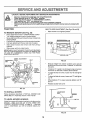
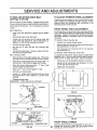
TO ADJUST
(See Fig. 34)
If unit requires more than six (6) feet stopping distance at
high speed in highest gear, then brake must be adjusted,
Remove mower (See "TO REMOVE MOWER" in this
section of this manual).
Remove four (4) hex washer head tapping screws from
shift cover plate located on top of tractor frame. Remove the cover plate.
Remove screws and idler arm nut securing mower belt
cover and remove cover_
Loosen am nut (A) on brake rod (B) at clevis (C) (Fig
36). fyou f nd t d fficu t to loosen jam nut (A), remove
cover plate in L.H frame rail
Roll belt over the top of the R,H. mandrel
Pull belt off all other mandrels,
may
(See Figs. 35 and 36)
Your unit is equipped with an adjustable brake system
which is mounted on the right side of the transaxle
Park the tractor on level surfaCer Engage parking brake.
For assistance, there is a belt installation guide decal on the
underside of mower belt cover.
Remove any dirt and grass which
accumulatend mandrels or idler arm.
BRAKE
Rotate brake rod (b) counterclockwise, turning brake
rod out of clevis (c) four (4) to six (6) turns.
have
Start tractor with transaxle in "N" (neutral) position,
Check deck idler arm assembly and flat idler to see that
they rotate freely.
Depress clutch/brake pedal to the point where the belt
stops moving, Hold clutch/brake pedal in position by
engaging parking brake If belt beings to move after
engaging parking brake, depress clutch/brake pedal to
next notch on parking brake
Be sure spring is hooked in deck idler arm assembly
and on bolt in mower housing,
Insta{I new be{t in groove of LrH mandrel pulley, lower
groove of center mandrelputley and around flat idler as
shown.
Shut engine Offr Rotate brake rod (B) clockwise by
hand, turning brake rod into clevis (C) until tight.
Tighten jam nut (A) on brake rod (B) at clevis (C) r
From a position at discharge end of mower, roll idler
belt into groove of RrH mandrel pulley.
Reinstall shift cover plate andfour 4) mountingscrews
If cover plate in LH rail was removed t shou d be
replaced.
Rotate center mandrel pulley by hand to make sure belt
is in grooves properly.
Reassemble top cover to deck. Tighten a!l screws and
idler arm nut securely,
SHIFT COVER
PLATE
Install mower to tractor (See "INSTALL MOWER AND
DRIVE BELT" in the Assembly section of this manual,
IDLER ARM NUT
FL_T IDLER
\
MANDREL
CENTRAL
PULLEY
FIG. 35
L.H, MANDREL
PULLEY
R.H. MANDREL
PULLEY
FIG. 34
POWER
TAKE
OFF (CLUTCH
PULLEY
FIG. 36
- See
Fig. 33)
"The power take-off clutch should provide years of serviee_
The clutch incorporates a built in brake that stops the pulley
almost immediately.
Eventually, the internal brake will
wear so the mower blades will not stop as recommended,
Adjustment should be made by your nearest Authorized
Service Center.
21
ERVICE AN
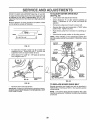
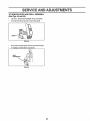
TO REPLACE MOTION
(See Figs. 37 and 38)
DRIVE
ADJUSTMENTS
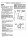
TO ADJUST
BELT
FRONT
BELT REMOVAL
ALIGNMENT
WHEEL
TOE-IN
ADJUSTMENT
Front wheel toe-in is required for proper steering operation
Toe-in was set at the factory and adjustment should not be
necessary If parts in the front axle or steering mechanism
have been replaced or damaged, check to-in and adjust if
necessary.
negative ground battery
Set parking brake (to get belt slack)
Loosen (do not remove) two (2) engine pulley belt
guide bolts and swivel RH. side of belt guide up.
Tighten LH bolt ot hold belt guide in position,
TO CHECK TOE-IN (See Fig 39)
Position front wheels straight ahead.
Measure distance between wheels at front and rear of
tires (dimensions "A" and "B").
Front dimension "A" should be 1/8" to 1/4" less than
rear dimension "B"_
Roll belt off engine pulley.
Roll belt off "V" idler, flat idler and clutching idler
pulleys.
Pull belt off clutch pulley - between pulley and frame
Pull belt off transaxte pulley.
TO ADJUST TOE-IN (See Figs 39 and 40)
BELT INSTALLATION
It is important that both tie rods be equal in length before
ad usting toe-in. Both tie rods should measure approximately 10-1/4" in length (see inset). Adjust f necessary.
Push belt down from engine pulley area. Place back
(flat) side of belt on flat idler (flat idler is next to frarne).
Loosen jam nuts at adjustment sleeves on tie rods.
Place belt on clutching idler and over clutch pulley, "V"
(narrow) part of belt should engage clutch pulley
Place belt around transaxle pulley,
should engage transaxle pulley
WHEEL
If steering wheel crossbars are not horizontal (left to right)
when wheels are positioned straight forward, remove
steering wheel and reassemble per instructions in the
Assembly section of this manual
Park the tractor on level surface. Engage parking brake
For ease of servicethere is a belt installation guide decal on
bottom side of left footrest It is not necessary to remove
mower,
Raise hood and disconnect
cable
STEERING
Adjust both tie rods equally until dimension "A" is 1/8"
to 1/4" less than dimension "B",
"V" part of belt
Tighten jam nuts securely.
Make sure "V" part of belt engages "V" idler.
Roll belt over engine pulley.
Loosen L H engine pulley belt guide bolt and swivel
belt guide on to RH, bolt, Tighten L,H. and R,H bolts
securely.
•
Release parking brake.
IMPORTANT: CHECK BRAKE ADJUSTMENT.
_____1
F ONTOFTRAOTOR
LH. BOLT
"--A
O
FIG. 39
ADJUSTMENT
ROD
....
-=
SLEEVES
-
-
-
©
R.H, BOLT
FIG. 37
FLAT IDLER
CLUTCH
....
PULLEY
JAM NUTS
FIG, 40
FRONT
"V" IDLER
CLUTCHING
IDLER
FIG. 38
TRANSAXLE
PULLEY
22
WHEEL
CAMBER
The front wheel camber is not adjustable on your unit If
damage has occurred to affect the front wheel camber.
contact your n,_r_t Alithnri7 "t _; ,,,_r. r" _t .
i,,i
SERVUCE AND ADJUSTMENTS
i,
TO REMOVE
WHEEL
FOR
TO ATTACH JUMPER CABLES Connect each end of the RED cable to the POSITIVE
(+) terminal of each battery, taking care not to short
against chassi&
Connect one end of the BLACK cable to the NEGATIVE (-) terminal of fully charged battery°
Connect the other end of the BLACK cable to good
CHASSIS GROUND. away from fuel tank and battery,
REPAIRS
FRONT WHEEL (See Fig, 41) Block up axle securely,
Remove hub cap, retaining ring and washers to allow
wheel removal,
Repair tire and reassemble,
Replace washers and snap retaining ring securely in
axle groove,
Replace hub cap.
TO REMOVE CABLES, REVERSE ORDER BLACK cable first from chassis and fully charged
battery.
RED cable last from both batteries.
WASHERS
RETAIN{NG
TO REPLACE
FUSE
Replace with 30 amp automotive-type plug-in fuse
fuse holder is located behind the dash,
TO REPLACE
HEADLIGHT
The
BULB
Raise hood.
HUBCAP
Pull bulb holder out of the hole in the backside of the
grill,
FIG. 41
Replace bulb in holder and push bulb holder securely
back into the hole in the backside of the grill,
Close hood,
REAR WHEELBlock rear axle securely,
Remove five (5) hub bolts to allow wheel removal
Repair tire and reassemble. Replace and tighten hob
bolts securely.
TO ADJUST ATTACHMENT
(See Fig. 43)
LIFT SPRING
While holding spring bushing with wrench, loosen jam
nut,
TO START ENGINE WITH A WEAK BATTERY (See Fig. 42)
Turn adjustment bolt clockwise to extend spring and
reduce lift effort (for heavier attachments),
CAUTION: Lead-acid batteries generate
explosive gases. Keep sparks, flame and
smoking materials away from batteries.
Always wear eye protection when around
batteries.
Turn adjustment bolt counterclockwise
tachments),
(for lighter at-
Retighten jam nut against spring bushing.
IMPORTANT: DO NOT ADJUST FOR MAXIMUM SPRING
TENSION WHEN USING LIGHT ATTACHMENTS SUCH
ASAMOWER
ADJUST LIFT LEVER SPRING TO AID IN
LIFTING ATTACHMENT. DO NOT OVERPOWER SPRING.
WHEN REMOVING ATTACHMENT, ALWAYS ADJUST TO
SPRING TENSION TO ITS LOWEST POSITION,
If your battery is too weak to start the engine, it should be
recharge&
If "jumper cables" are used for emergency
starting, follow this procedure:
IMPORTANT:
YOUR UNIT IS EQUIPPED WITH A 12
VOLT NEGATIVE GROUNDED SYSTEM. THE OTHER
VEHICLE MUST ALSO BE A 12 VOLT NEGATIVE
GROUNDED SYSTEM. DO NOT USE YOUR TRACTOR
BATTERY TO START OTHER VEHICLES,
ADJUSTMENT
BOLT
SPRING
BUSHING
ATTACHMENT
UFT SPRING
JAM NUT
"POSITIVE"
"NEGATIVE"
(+)
(-)
FIG. 43
FIG. 42
23
ii,ll
,llll
i,ii
,,,,i
,i
SERVICE
ADJUSTMENTS
i
TO REMOVE
i i
liN,,i
HOOD AND GRILL ASSEMBLY
(See Figs. 44 and 45)
Lift hood. Disconnect headlight wiring connectiorL
Unscrew one screw at rear of each side panel.
FIG. 44
Pivot hood and side panel forward and lift off tractor.
To replace, reverse above procedure.
WIRE
CONNECTION
FIG. 45
24
ii,
ill
SERVICEAND
=li,,
ADJ
i,,,,,i
ENGINE
TO ADJUST
THROTTLE
(See Fig. 46)
CONTROL
STMF_.NT$
High speed stop is factory adjusted, Do not adjust-damage
may result,
IMPORTANT:
NEVER TAMPER
WITH THE ENGINE
GOVERNOR,
WHICH IS FACTORY
SET FOR PROPER
ENGINE SPEED_ OVERSPEEDING
THE ENGINE ABOVE
THE
FACTORY
HIGH
SPEED
SETTING
CAN BE
DANGEROUS
IF YOUTHINKTHEENGINE-GOVERNED
HIGH SPEED NEEDS
ADJUSTING,
CONTACT
YOUR
NEAREST
SEARS
SERVICE
CENTER,
WHICH HAS
PROPER EQUIPMENT AND EXPERIENCE
TO MAKE ANY
NECESSARY
ADJUSTMENTS
CABLE
The throttle control has been preset at the factory and
adjustment should not be necessary Check adjustment as
described below before loosening cable If adjustment is
necessary, proceed as follows:
With engine not running, move throttle control lever to
"FAST" position,
Check that throttle lever is against high speed stop If
it is not, loosen clamp screw and pull throttle cable until
lever is against stop, Tighten clamp screw securely
TO ADJUST
CARBURETOR
CLAMP
CREW
(See Fig. 47)
TH RoI-rLE LEVER
SHOWN IN HIGH
SPEED POSITION
THROTTLE LEVER
SHOWN IN LOW
The carburetor has been present at the factory and adjustment should not be necessary. However, minor ad ustment
may be required to compensate for differences in fuel,
temperature, altitude or load. If the carburetor does not
need adjustment, proceed as follows:
In general, turning the adjusting needles in (clockwise)
decreases the supply of fuel to the engine giving a leaner
fuel/air mixture, Turning the ad usting needles out (counterc ockw se) ncreases the supp y of rue to the eng ne
giving a richer fuel/air mixture,
IMPORTANT:
DAMAGE TO THE NEEDLES AND THE
SEATS IN CARBURETOR MAY RESULT IF SCREW IS
TURNED IN TOO TIGHT
/"
[
j
jf
PRELIMINARY SETTING •
Be sure you have a clean air filter, and the throttle_
control cable and choke are adjusted properly (see
above).
INNER WIRE
HIGH SPEED STOP
With engine offtum idle fuel adjusting needle in (clockwise) closing it finger tight and then turn out (counterclockwise) 1-1/4 turn.
FINAL SETTING -
FIG. 46
IDLE SPEED
ADJUSTING
SCREW
Start engine and allow to warm for five minutes. Make
final adjustments with engine running and shift/motion
control lever in "NEUTRAL" position.
IDLE FUEL
NEEDLE
With throttle control lever in "FAST" position, turn main
fuel adjusting needle in (clockwise) until engine begins
to die then turn out (counterclockwise) until engine
runs rough. Turn needle to a point midway between
those two positions.
FUEL
ADJUSTING
NEEDLE
Id!e speed setting -With throttle control lever in"SLOW"
position, engine should idle at 1200 RPM, If engine
idles too slow or fast. turn idle speed adjusting screw in
or out until correct idle is attained
FIGo 47
Idle fuel needle setting - With throttle control lever in
"SLOW" position, turn idle fuel adjusting needle in
(clockwise) until engine begins to die and then turn out
(counterclockwise) until engine runs rough. Turn needle
to a point midway between those two positions,
Recheck idle speed, Readjust if necessary.
ACCELERATION TEST Move throttle control lever from "SLOW" to "FAST"
position, If engine hesitates or dies, turn idle mixture
screwout (counterclockwise) 1/Stum, Repeattest and
continue to adjust, if necessary, until engine accelerates smoothly,
25
ii
STORAGE
i i
"HI
ENGINE
Immediately prepare your unit for storage at the end of the
season or if the unit will not be used for 30 days or more.
A
FUEL SYSTEM
IMPORTANT:
IT IS IMPORTANT TO PREVENT GUM
DEPOSITS FROM FORMING IN ESSEN*flAL FUEL
SYSTEM PARTS SUCH AS CARBURETOR, FUEL FILTER,
FUEL HOSE, OR TANK DURING STORAGE. ALSO,
EXPERIENCE INDICATES THAT ALCOHOL BLENDED
FUELS (CALLED GASOHOL OR USING ETHANOL OR
METHANOL) CAN ATTRACT MOISTURE WHICH LEADS
TO SEPARATION AND FORMATION OF ACIDS DURING
STORAGE. ACIDIC GAS CAN DAMAGE THE FUEL
SYSTEM OF AN ENGINE WHILE IN STORAGE.
CAUTION: Never store the tractor with
gasoline in the tank Inside a building
where fumes may reach an open flame
or spark, Allow the engine to cool
before storing In any enclosure.
.111
TRACTOR
Drain the fuel tank.
Remove mower from unit for winter storage. When mower
is to be stored for a period of time, clean it thoroughly,
remove all dirt, grease, leaves, etc. Store in a clean, dry
area.
Start the engine and let it run until the fuel lines and
carburetor are empty,
Never use engine or carburetor cleaner' products in the
fuel tank or permanent damage may occur_
Use fresh fuel next season.
Clean entire tractor (See"CLEANING" in the Customer
Responsibilities section of this manual).
NOTE: Fuel stabilizer is an acceptable alternative in
minimizing the formation of fuel gum deposits during storage. Add stabilizer to gasoline in fuel tank or storage
container. Run engine at least 10 minutes after adding
stabilizer to allow the stabilizer to reach the car buretor. Do
not drain the gas tank and carburetor if using fuel stabilizer.
Inspect and replace belts, if necessary (See belt replacement instructions in the Service and Adjustments
section of this manual).
Lubricate as shown in the Customer Responsibilities
section of this manual.
Be sure that a!l nuts, bolts and screws are securely
fastened. Inspect moving parts for damage, breakage
and wear. Replace if necessary.
ENGINE
OIL
Drain oil (with engine warm) and replace with clean engine
oil. (See "ENGINE" in the Customer Responsibilities section of this manual).
Touch up all rusted or chipped paint surfaces; sand
lightly before painting.
BATTERY
CYLINDERS
Fully charge the battery for storage.
Remove spark plug(s),
After a period of time in storage, battery may require
recharging_
Pour one ounce of oil through spark plug hole(s) into
cylinder(s),
To help prevent corrosion arrd power leakage during
long periods of storage, battery cables should be
disconnected and battery cleaned tho!oughly (see "TO
CLEAN BATTERYANDTERMINALS
intheCustorner
Responsibilities section of this manual),
Turn ignition key to "START" position for a few seconds
to distribute oil,
Replace with new spark plug(s).
After cleaning, leave cables disconnected and place
cables where they cannot come in contact with battery
terminals.
OTHER
Do not store gasoline from one season to another.
Be sure battery drain tube is securely attached to drain
in battery tray.
Replace your gasoline can if your can starts to rust.
Rust and/or dirt in your gasoline will cause problems.
If possible, store your unit indoors and cover it to give
protection from dust and dirt
Cover your unit with a suitable protective cover that
does not retain moisture. Do not use plastic. Plastic
cannot breathe which allows condensation to form and
will cause your unit to rust
IMPORTANT: NEVER COVER TRACTOR WHILE ENGINE
AND EXHAUST AREAS ARE STILL WARM,
26
TROUBLESHOOTUNG
PROBLEM
CAUSE
Will notstart
1.
2
3_
4.
5.
6.
7.
8,
9
10
Herd to start
Engine will not turn over
1.
2,
3
4,
5,
6
7
8
1,
2
3
4,
5
6.
7
8
9.
10
POmNTS
CORRECTION
Out offuel
Enginenot"CHOKED"properly.
Engine flooded
Bad spark plug
Dirty air filter.
Dirty fuel filter.
Water in fuel
1.
2.
3
4
5
6
7.
Loose or damaged wiring,
Carburetor out of adjustment
Engine vatves out of adjustment.
8,
9.
10.
Dirty air filter
Bad spark plug
Weak or dead battery
Dirty fuel filter
Stale or dirty fuel
Loose or damaged w_ring,
Carburetor out of adjustment
Engine valves out of adjustment
1
2
3,
4
5,
6
7
8
1.
2.
3
4
5
6
7
8
9.
10
Ckdch/brake pedal not depressed
Attachment clutch is engaged
Spark plug wire is disconnected
Weak or dead battery
Blown fuse,
Corroded battery terminals
Loose or damaged wiring
Faulty ignition switch
Faulty solenoid or starter
Faulty operator presence switch(as)
Fillfuel tank.
See TO START ENGINE in Operation section.
Wait several minutes before attempting to start.
Replace spark plug
Clean/replace air filter
Replace fuel filter
Drain fuel tank and carburetor, refill tank with fresh
gasoline and replace fuelfilter.
Check allwldng
ContactSears Service Department.
Contact SearsServ_ce Department
Clean/replace a_r filter
Replace spark plug
Recharge or replace battery,
Replace fuel filter,
Drain fuel tank and refill with fresh gasoline,
Check all widng
Contact Sears Service Department
Contact Sears Service Department
Depress clutch/brake pedal
Disengage attachment clutch
Connect wire to spark plug.
Recharge or replace battery,
Replace fuse
Clean battery terminals.
Check all wiring
Check/replace ignition switch.
Check/replaca solenoid or starter
Contact Sears Service Department.
ii
Engine clicks but will not
start
1
2
3
4.
Weak or dead battery
Corroded battery terminals
Looseor damaged wiring.
Faulty solenoid or starter
I
2
3
4
Recharge or replace battery.
Clean battery terminals
Check allwiring
Check/replaca solenoid orstarter,
IH
Loss of power
1
2
3
4.
5
6
7.
8
9
10
11.
12
13.
14
15,
Excessive
vibration
Cutting too much grass/too fast
Throttle in"CHOKE" position.
Build-up of grass, leaves and trash under mower
Dirty air filter
Low Oil Leve!/dirtyoil
Faulty spark plug
Dirty fueliitter
Stale or dirtyfuet
Water in fuel
10
11
12.
13
14.
15
Spark plug wire loose
Dirty engine air screen/fins
Dirty/clogged mufiIer
Loose or damaged wiring
Carburetor out of adjustment
Engine valves out of adjustment,
1
2,
Worn. bent or loose blade
Bent blade mandrel
3
Loose/damaged
1.
2
3
4
5
6
7
8
9
1.
2
3
part(s)
27
ii
i,,
Set _n"Higher Cut" position/reduce speed
Adjust throttle control
Clean underside of mower housing.
Clean/reptaca air filter
Check oi! level/change oil
Clean and regap or change spark plug,
Replace fuelfilter
Dra_nfuel tank and refillwith fresh gasollne_
Drain fuel tank and carburetor, refill tank with fresh
gasoline and replace fuel filter.
Connect and tightenspark plug wire.
Clean engine air screen/fins
Clean/replaca muffler
Check all wlring.
Contact Sears Service Department.
Contact Sears Service DepartmenL
Replace blade Tighten btade bolt,
Repiace blade mandrel
Tighten loose part(s)
Replace damaged parts,
TROUBLESHOOTi
POmNT$
PROBLEM
CAUSE
CORRECTION
Engine continues to run
when operator leaves seat
with attachment clutch
engaged
1.
Faultyoperator=safetypresencecontrolsystem
1
Poorcut-uneven
1.
2.
3.
4
Worn, bent or loose blade
Mower deck not level.
Buildup of grass, leaves, and trashunder mower
Bent blade mandrel
! 1_
2.
I3
4.
Mower bledeswgl not
rotate
1.
2,
3.
4
5.
Obstruction in clutch mechanism
Mower drive belt out of adjustment.
Worn/damaged mower drive belt
Frozen Idler pulley.
Frozen blade mandrel.
11. Remove obstruction
2 Adjust mower drive belt
3. Replace mower drive bell
4. Replace idlerpulley.
5. Replace blade mandrel
Poor grass discharge
1.
2
3,
4
Engine speedtoo slow
Travel speed too fast
Wet grass
Mower deck not level.
5.
6.
Low/uneven tire air pressure
Worn, bent or loose blade
Buildup of grass, leaves and trash un_'er mo_er
Mower drive belt worn or out of adju,_'tment
Blades Improperly installed.
improper blades used.
I 1. Place throttlecontrolin "FAST" position.
2. Shift to slower speed,
3 Allowgrassto dry before mowing.
4 Levelmower deck
5 Check tiresfor properair pressure.
: 6 Replace/sharpenblade Tighten blade bolt,
7 Clean undersideof mower housing
8 Replace/adjustmower drive belt
9, Reinsta]!blades sharpedge down,
10. Replace with blades listed in this manual
1. Turn switch"ON"
2 Replace bulb(s)
'-3,_*.Cbeck/replace light switch
4 Checkwirtng andconnecttons
5. Replace fuse
,,,
7
8
9
10.
Headlight(s) not working
(if so equipped)
1
2
3
4.
5
Switch is "OFF"
Bulb(s) burned out
Faultytightswitch
Looseor damaged wiring.
Blownfuse
Battery will not charge
1.
2.
3
4.
Bad batterycelffs)
Poor cable connections
Fau{tyregulator (if so equipped)
Faulty alternator
1
2.
3
4.
9;q
,,
i
Check wiring,switches and connections,tf not
corrected,contactSears ServiceDepartmenL
Replace blade_ Tighten blade bolt
Levelmower deck.
Clean underside of mower housing
Replace blade mandrel.
Replace battery.
Check/clean all connections
Replace regulator.
Replace artemator