1
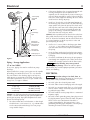
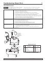
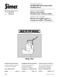
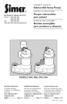
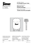
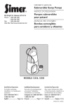
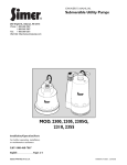
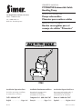
OWNER’S MANUAL
PITMASTER Submersible Solids
Handling Pump
293 Wright Street, Delavan, WI 53115
Phone: 1-800-468-7867
Fax: 1-800-390-5351
NOTICE D’UTILISATION
Pompe submersibles
Pitmaster pour matières solides
Web Site: SimerPump.com
MANUAL DEL USUARIO
Bomba sumergibles para el
manejo de sólidos “Pitmaster”
3963
Installation/Operation/Parts
Installation/Fonctionnement/Pièces
Instalación/Operación/Piezas
For further operating, installation,
or maintenance assistance:
Pour plus de renseignements
concernant l’utilisation,
l’installation ou l’entretien,
Para mayor información sobre el
funcionamiento, instalación o
mantenimiento de la bomba:
Call 1-800-468-7867
Composer le 1 (800) 468-7867
Llame al 1-800-468-7867
English . . . . . . . . . . . . . . . Pages 2-6
Français . . . . . . . . . . . . Pages 7-11
Español . . . . . . . . . . .Páginas 12-16
© 2011
SIM185 (6/17/2011)
Safety / Specifications / Performance / Installation
READ AND FOLLOW
SAFETY INSTRUCTIONS!
This is the safety alert symbol. When you see this
symbol on your pump or in this manual, look for
one of the following signal words and be alert to the
potential for personal injury:
warns about hazards that will cause serious
personal injury, death or major property damage if
ignored.
warns about hazards that can cause serious
personal injury, death or major property damage if
ignored.
warns about hazards that will or can cause
minor personal injury or property damage if ignored.
The label NOTICE indicates special instructions which
are important but not related to hazards.
Carefully read and follow all safety instructions in this
manual and on pump.
Keep safety labels in good condition.
Replace missing or damaged safety labels.
1. Read this manual carefully. Failure to follow these
instructions could cause serious bodily injury and/or
property damage.
2. Check your local codes before installing. You must
comply with their rules.
3. Vent sewage or septic tank according to local codes.
4. Do not install pump in any location classified as
hazardous by National Electrical Code, ANSI/NFPA
70-1990.
Hazardous voltage. Can shock, burn or
cause death. During operation, the pump is in water.
To avoid fatal shocks, proceed as follows if pump needs
servicing:
5A. Disconnect power to outlet box before unplugging
pump.
5B. Take extreme care when changing fuses. Do not
stand in water or put your finger in fuse socket.
2
5C. Do not modify cord and plug. When using cord and
plug, plug into a grounded outlet only. When wiring
to a system control, connect pump ground lead to
system ground.
6. Do not run pump dry. Dry running can overheat
pump, (causing burns to anyone handling it) and will
void warranty.
7. Pump normally runs hot. To avoid burns when servicing pump, allow it to cool for 20 minutes after
shut-down before handling it.
8. In normal service, motor should not need oiling.
Motor has been filled at the factory with a special oil.
INSTALLATION
(See Figure 1 for Typical Installation instructions.)
NOTICE: Pump must be level when operating. If motor
is tilted, internal start/run switch may overheat and damage motor.
Risk of electrical shock. Can burn or kill.
Do not lift pump by power cord. See “Cord Lift Warning”
on Page 4. Do not hang pump from discharge pipe or
power cord.
1. Install the pump on a solid, level foundation, or in a
sump pit constructed of tile, concrete, steel or plastic. The recommended minimum diameter of the
sump pit is 18" (46cm) diameter and the minimum
recommended depth is 30" (76cm). Check local
codes for approved materials.
NOTICE: Pump should not be installed on clay, earth
or sand surfaces. Clean the area around the pump of
small stones and gravel which could clog the pump.
Keep the pump inlet screen clear.
2. Thread a 2” discharge pipe into the pump 2” NPT
discharge port. Be careful to avoid stripping or crossing threads.
Piping – Effluent Applications
(3/4" or Less Solids)
Piping must be 1-1/2" minimum to carry volume of pump
discharge. Check local codes to determine if a check
valve is required in your system. In cold climates, check
valves are not used to prevent effluent from freezing in
piping.
SPECIFICATIONS
Model
3963
H.P.
1/2
Voltage
115
Individual Branch Circuit
Required (Amps)
20
Dual Element Time
Delay Fuse Amps
20
PERFORMANCE
3963
GPH (LITERS) AT DISCHARGE FT. OF HEAD
5 (1.5m)
10 (3m)
15 (4.6m)
7320(27,709)
5400(20,441)
2700(10,221)
20 (6.1m)
–
For parts or assistance, call Simer Customer Service at 1-800-468-7867
25 (7.6m)
–
Electrical
3
Flow
Directional
Arrow
115V Properly
Grounded
Outlet
2" Checkvalve
Do Not Mount
Vertically
Sump Pit
2" Discharge
Pipe
30"
Be sure the
float switch can
swing through
it's entire arc.
Drill a 3/16"
vent hole here.
Install pump on
a hard, level surface.
18"
Figure 1
Piping – Sewage Applications
(2" or Less Solids)
In any case, piping must not be smaller than pump
discharge.
When installed in a sewage system, pipe must be capable
of handling semi-solids of at least 2” (5.1 cm) diameter.
The rate of flow in the discharge pipe must keep any
solids present in suspension in the fluid. To meet minimum flow requirements (2 feet (.6 m) per second in discharge line), size pipe as follows:
A Pipe Size Of:
1-1/2” (3.8 cm)
2” (5.1 cm)
2-1/2” (6.3 cm)
3” (7.6 cm)
Will Handle a Flow Rate Of:
12 GPM (45 LPM)
21 GPM (79 LPM)
30 GPM (113 LPM)
48 GPM (181 LPM)
NOTICE: Use PTFE pipe thread sealant tape on pipe connections. Do not use ordinary pipe joint compound on
plastic pipe or pump. Pipe joint compound can attack
plastics and damage pump.
3. To reduce motor noise and vibrations, a short length
of rubber hose (1-5/8"(41mm) I.D., e.g. radiator hose)
can be connected into discharge line near pump
using suitable clamps.
4. If the pump discharge line is exposed to outside subfreezing atmosphere, then the portion of line
exposed must be installed so any water remaining in
pipe will drain to outfall by gravity. Failure to do this
can cause water trapped in discharge to freeze which
could result in damage to pump.
5. Install a 2” check valve in the horizontal portion of
the discharge pipe. Make certain, the flow indicating
arrow, points away from the pump. This check valve
will keep the water from either running back into the
basin or into the area being pumped out when the
pump is not running. Check valve should be a free
flow valve that will easily pass solids.
NOTICE: For best performance of check valve when handling solids, do not install it with discharge angled more
than 45° above the horizontal. Do not install check valve
in a vertical position as solids may settle in valve and
prevent opening on startup.
6. Drill a 3/16” (4.7mm) hole in discharge pipe about
1"-2” (2.5 - 5.1cm) above pump discharge connection (but below check valve) to prevent airlocking
the pump.
7. Insert the float switch piggy-back plug into a properly grounded outlet and the pump plug into the piggyback plug.
8. Check the installation by observing the pump operation through one complete cycle. Make sure that no
parts of the assembly interfere with the float switch.
Risk of flooding. May cause personal
injury or property damage. Failure to make this operational check may lead to improper operation, premature
failure, and flooding.
ELECTRICAL
Hazardous voltage. Can shock, burn, or
cause death. When installing, operating, or servicing this
pump, follow safety instructions listed below.
1. DO NOT splice the electrical power cord.
2. DO NOT allow electrical cord plug to be submerged.
3. DO NOT use extension cords. They are a fire hazard
and can reduce voltage sufficiently to prevent pumping and/or damage motor.
4. DO NOT handle or service pump while it is connected
to power supply.
5. DO NOT remove grounding prong from plug or modify plug.To protect against electrical shock, the power
cord is a three-wire conductor and includes a
3-prong grounded plug. Plug pump into a 3-wire,
grounded, grounding-type receptacle. Connect pump
according to electrical codes that apply.
For parts or assistance, call Simer Customer Service at 1-800-468-7867
Operation / Service
4
For automatic operation, plug or wire pump into an automatic float switch or pump controller. Pump will run continuously when plugged directly into an electrical outlet.
Connect or wire pump to its own individual branch circuit
with no other outlets or equipment in the circuit. Size
fuses or circuit breakers according to chart on Page 2.
SERVICE
Risk of electrical shock and fire. Can burn or
cause death. Be sure that power supply information
(Voltage/Hertz/Phase) on pump motor nameplate matches
incoming power supply exactly. Install pump according to
all electrical codes that apply.
Risk of electrical shock. Can burn or kill.
Do not lift pump by power cord. See “Cord Lift Warning”
below.
OPERATION
NOTICE: Do not allow pump to run in a dry sump. It
will void the warranty and may damage the pump.
An automatic overload protector in the motor will protect motor from burning out due to overheating/overloading. When motor cools down, overload protector will
automatically reset and start motor.
If overload trips frequently, check for cause. It could be a
stuck impeller, wrong/low voltage, or electrical failure in
motor. If an electrical failure in the motor is suspected,
have it serviced by a competent repairman.
Hazardous voltage. Can shock, burn, or
cause death. Before removing pump from basin for service, always disconnect electrical power to pump and
control switch.
Submerge pump in a disinfectant solution (chlorox or
chlorine) for at least one hour before disassembling
pump.
The pump motor contains a special lubricating oil which
should be kept clean and free of water at all times.
Check operation by filling sump with water and observing pump operation through one complete cycle.
Risk of flooding. May cause personal
injury or property damage. Failure to make this operational check may lead to flooding and premature failure.
NOTICE: This unit is not designed for applications
involving salt water or brine! Use with salt water or brine
will void warranty.
Pump is permanently lubricated. No oiling or greasing is
required.
CORD LIFT WARNING
WARNING
1. Attempting to lift or support pump by
power cord can damage cord and
cord connections.
2. Cord may pull apart, exposing bare
wires with possibility of fire or electrical shock.
3. Lifting or supporting pump by power
cord will void warranty.
Risk of electrical
shock.
Can burn or kill.
Do not lift pump by
power cord.
4. Use lifting ring or handle on top of
pump for all lifting/lowering of pump.
Disconnect power to pump before
doing any work on pump or attempting to remove pump from sump.
For parts or assistance, call Simer Customer Service at 1-800-468-7867
Troubleshooting / Repair Parts
5
TROUBLESHOOTING
Risk of sudden starts. Can result in electrical
shock or pinching of hands or tools. If power to pump is on
when thermal overload resets, pump may start without
warning. Disconnect power before servicing pump.
A. Pump fails to operate:
1. Check to be sure that power cord is securely plugged into outlet. Disconnect power to
outlet before handling pump or motor.
2. Check to be sure you have electrical power.
3. Check that liquid fluid level is high enough to activate switch or controller.
4. Check to be sure that 3/16" (4.7 mm) vent hole in discharge pipe is not plugged.
5. Check for blockage in pump inlet, impeller, check valve or discharge pipe.
6. Thermal overload may have tripped. Test start pump; if it starts and then stops immediately,
disconnect from power source for 30 minutes to allow motor to cool, then reconnect to
power source. Check for cause of overheating/overloading.
7. Check the float switch operation for maximum possible clearance.
B. Pump fails to empty sump:
1.
2.
3.
4.
5.
C. Pump will not shut off:
1. Check switch or controller automatic floats for proper operation, location and clearance.
See installation instructions for switch/controller.
2. If pump is completely inoperative or continues to malfunction, consult your local
serviceman.
Be sure all valves in discharge valve are fully open.
Clean out discharge pipe and check valve.
Check for blockage in pump inlet or impeller.
Pump not sized properly. A higher capacity pump may be required.
Check the float switch operation for maximum possible clearance.
3
4
Lift pump
using this
handle ring
only.
REPAIR PARTS LIST
2
Key
No.
Part
Description
Qty
3963
115 Volt
1
1
2
3
4
Volute
Impeller
Power Cord
Automatic Float Switch
1
1
1
1
PW1-13
PW5-11P
PW117-237-TSE
PS117-145P
IF MOTOR FAILS, REPLACE PUMP.
For parts or assistance, call Simer Customer Service at 1-800-468-7867
Warranty
6
Retain Original Receipt For Warranty Eligibility
Limited Warranty
This Limited Warranty is effective June 1, 2011 and replaces all undated warranties and warranties dated before June 1, 2011.
SIMER warrants to the original consumer purchaser (“Purchaser” or “You”) that its products are free from defects in material and
workmanship for a period of twelve (12) months from the date of the original consumer purchase. If, within twelve (12) months from
the original consumer purchase, any such product shall prove to be defective, it shall be repaired or replaced at SIMER’s option,
subject to the terms and conditions set forth herein. Note that this limited warranty applies to manufacturing defects only and not to
ordinary wear and tear. All mechanical devices need periodic parts and service to perform well. This limited warranty does not cover
repair when normal use has exhausted the life of a part or the equipment.
The original purchase receipt and product warranty information label are required to determine warranty eligibility. Eligibility is based
on purchase date of original product – not the date of replacement under warranty. The warranty is limited to repair or replacement
of original purchased product only, not replacement product (i.e. one warranty replacement allowed per purchase). Purchaser pays
all removal, installation, labor, shipping, and incidental charges.
For parts or troubleshooting assistance, DO NOT return product to your retail store. Contact SIMER Customer Service at
1-800-468-7867.
Claims made under this warranty shall be made by returning the product (except sewage pumps, see below) to the retail outlet
where it was purchased or to the factory immediately after the discovery of any alleged defect. SIMER will subsequently take
corrective action as promptly as reasonably possible. No requests for service will be accepted if received more than 30 days after
the warranty expires. Warranty is not transferable and does not apply to products used in commercial/rental applications.
Sewage Pumps
DO NOT return a sewage pump (that has been installed) to your retail store. Contact SIMER Customer Service. Sewage pumps
that have seen service and been removed carry a contamination hazard with them.
If your sewage pump has failed:
•
Wear rubber gloves when handling the pump;
•
For warranty purposes, return the pump’s cord tag and original receipt of purchase to the retail store;
•
Dispose of the pump according to local disposal ordinances.
Exceptions to the Twelve (12) Month Limited Warranty
Product
Warranty Period
BW85P, M40P
90 days
2115, 2300, 2310, 2330, 2943, 2955, 2956, 2957, A5500
2 Years
4” Submersible Well Pumps, 2945, 2958, 2975PC, 3075SS, 3963, 3984, 3995
3 Years
Pre-Charged Pressure Tanks, 3985, 3986, 3988, 3989, 5910, 5950, 5955, 5965, 5975
5 Years
General Terms and Conditions; Limitation of Remedies
You must pay all labor and shipping charges necessary to replace product covered by this warranty. This warranty does not apply to
the following: (1) acts of God; (2) products which, in SIMER’s sole judgment, have been subject to negligence, abuse, accident,
misapplication, tampering, or alteration; (3) failures due to improper installation, operation, maintenance or storage; (4) atypical or
unapproved application, use or service; (5) failures caused by corrosion, rust or other foreign materials in the system, or operation
at pressures in excess of recommended maximums.
This warranty sets forth SIMER’s sole obligation and purchaser’s exclusive remedy for defective products.
SIMER SHALL NOT BE LIABLE FOR ANY CONSEQUENTIAL, INCIDENTAL, OR CONTINGENT DAMAGES WHATSOEVER.
THE FOREGOING LIMITED WARRANTIES ARE EXCLUSIVE AND IN LIEU OF ALL OTHER EXPRESS AND IMPLIED
WARRANTIES, INCLUDING BUT NOT LIMITED TO IMPLIED WARRANTIES OF MERCHANTABILITY AND FITNESS FOR A
PARTICULAR PURPOSE. THE FOREGOING LIMITED WARRANTIES SHALL NOT EXTEND BEYOND THE DURATION
PROVIDED HEREIN.
Some states do not allow the exclusion or limitation of incidental or consequential damages or limitations on how long an implied
warranty lasts, so the above limitations or exclusions may not apply to You. This warranty gives You specific legal rights and You may
also have other rights which vary from state to state.
SIMER • 293 Wright Street • Delavan, WI U.S.A. 53115
Phone: 1-800-468-7867 • Fax: 1-800-390-5351 • Web Site: SimerPump.com
For parts or assistance, call Simer Customer Service at 1-800-468-7867