1
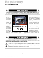
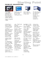
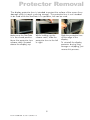
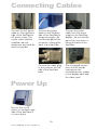
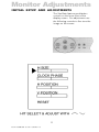
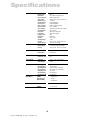
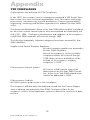
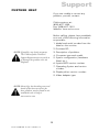
FIELD-READY FIELD-READY FIELD-READY STARGATE 18 User Manual Z ZMicrosystems Microsystems Doc# 27-0005UM Issued 11/00 Rev 1.0 Regulatory FCC INFORMATION 1. Use the power and video cables supplied with this equipment to help prevent interference with radio and television reception. The use of cables and adapters may cause interference with electronic equipment in the vicinity of this unit. 56)4/)6- & 2. This equipment has been tested and found to comply with the limits for Class A digital devices, pursuant to certain limits imposed 2 Doc# 27-0005UM Issued 11/00 Rev 1.0 by Part 15 of the FCC rules. These limits are designed to provide reasonable protection against harmful interference in when equipment is operated in commercial environments. This equipment generates, uses and can radiate radio frequency energy, and, if not installed and used in accordance with the instruction manual, may cause harmful interference to radio communications. 3. Operation of this equipment in a residential area is likely to cause interference in which case the user will be required to correct the interference at his own expense. Changes or modifications not expressly approved by Z Microsystems could void users authority to operate the equipment Contents STARTING POINT Shipment Contents User Manual Product Description Tools Required Precautions 4 4 4 5 6 6 MAINTENANCE Clean Front Panel 16 16 TROUBLESHOOTING 17 SPECIFICATIONS 18 INSTALL STARGATE 7 PROTECTOR REMOVAL 9 APPENDIX Warranty Y2K Compliance 19 19 22 CONNECTING CABLES 10 POWER UP 10 MONITOR ADJUSTMENTS Initial Setup And Adjustments Controls Saving Settings Tips And Techniques 11 11 12 13 14 SUPPORT Further Help Replacing Parts Providing Feedback 23 23 24 24 3 Doc# 27-0005UM Issued 11/00 Rev 1.0 Starting Point Congratulations on selecting a rugged field-ready StarGate -- the ultra rugged flat display. SHIPMENT CONTENTS USER MANUAL The StarGate shipping box contains the following: The User Manual comes in two formats: printed hardcopy or CDROM. This Manual is also available on the Z Microsystems website (www.zmicro.com). The StarGate AC Power Cable User Manual We recommend you read this manual as follows: Remember to save your original shipping container and packing material to transport or ship the unit. Carefully follow the instructions in the Installation chapter for hookup and initial control settings. Refer to the Operation chapter for a complete description of all the user controls, and the Maintenance and Troubleshooting chapters for care and correcting any unforeseen problems with the system. The Appendix chapters are provided for quickly finding technical information about the unit. 4 Doc# 27-0005UM Issued 11/00 Rev 1.0 Starting Point PRODUCT DESCRIPTION The rugged lightweight StarGate offers MIL-tailored high-end liquid crystal displays (LCDs) that can adapt to specific needs. Dual locks hold the StarGate firmly in the viewing position. Quick release levers allow it to swing open. The StarGate can be opened all the way for access to storage items and other sensitive equipment. A StarGate is built to easily withstand harsh environmental conditions. Automatic Phase Adjust functions lock to drifting graphic generator clocks and the Triple Frame Buffer allows a wide range of input signal refresh rates. rack. Dual locks hold the StarGate firmly in the viewing position. Quick release levers allow it to swing open for access to storage items and other sensitive equipment behind. Available in 16, 17, 18 and 20 active display areas, featuring up to 1280 x 1024 pixel resolution. StarGate displays plug-and-play with any workstation, PC or X-Terminal and with active-matrix LCD technology it provides astounding color and clarity. submarines, vehicles and mobile shelters. The StarGate is only 2.5 deep and 15.75 (9U) in height. It attaches to the front of RETMA rails in standard 19 racks and transit cases and requires no space inside the With special airborne and shipboard extended shock vibration and shock specifications, the StarGate will stand up to the most extreme environmental conditions. Fully sealed in a lightweight aluminum enclosure, the StarGate target application platforms include airplanes, helicopters, surface ships, 5 Doc# 27-0005UM Issued 11/00 Rev 1.0 The StarGate features a user replaceable safety glass protective lens, front control panel, and low power usage extends the life of the display. Also, radiation protection is designed into the system to make it less susceptible to electromagnetic interference. Starting Point TOOLS REQUIRED Required Tools and Equipment WARNING: To avoid shock hazard: Phillips screwdriver with about 10" shaft. Do not connect or disconnect the unit during an electrical storm. The power cord plug must be connected to a properly wired and grounded power outlet. Any equipment to which the unit will be attached must also be connected to properly wired and grounded power outlets The socket outlet shall be installed near the equipment and shall be easily accessible. . PRECAUTIONS In preparation to install the StarGate, take the following precautionary steps: NOTE: For the fastest and easiest installation of the StarGate, follow these steps in the sequence they are presented. Verify the StarGate power switch is off. If the power is off, the light on the front panel will not be illuminated. 6 Doc# 27-0005UM Issued 11/00 Rev 1.0 Install StarGate It is worth getting oriented to the StarGate before mounting it in the rack. The StarGate is a flat LCD that mounts on the front of the RETMA rails of a standard 19 rack. The dual locks can be seen on the vertical handle to the left. The display controls are located on the bottom below the display. Using both hands, press and slide the lock releases inside the handle on the left side of the display towards each other to release the locks and allow you to swing open the StarGate. On the right side of the back is the on/off switch, with the receptacle for the AC power cord on the power supply on the bottom. The StarGate display swings out to the right. The bracket that mounts to the front of the RETMA rails is on the left. On the top and bottom of the mounting bracket is the receptacle for securing the display flat against the rack. 7 Doc# 27-0005UM Issued 11/00 Rev 1.0 On the center left side of the back is the mini din receptacle for the power plug for the cord that leads from the power supply to the display. Also, the video connector. Install StarGate NOTE: All four screw holes in the RETMA rail must be visible through the four screw holes on both sides of the StarGate. If not, move the StarGate up or down until all four holes are visible. It is important to use the proper screws. To secure the StarGate to the frame, use four Panhead Phillips screws and washers on each side, for a total of eight. One person hold the right side of the StarGate, while the other person secures the first screw in the upper left corner of the unit. Before using any additional screws, check to see that all the remaining seven holes in the StarGate line up with the screw holes in the RETMA rails. Test the fit by opening and closing the StarGate several times. For a final adjustment, make sure that the back plate is flush against the RETMA rail and the back plate is square to the RETMA rails. Once positioned, tighten down the screws. Then secure the remaining seven screws. Do NOT tighten the screws. 8 Doc# 27-0005UM Issued 11/00 Rev 1.0 NOTE: Installing the StarGate requires two people, one to hold the unit, while the other secures the unit with screws. Test the adjustment by opening and closing the StarGate display several times. If there is any binding, check for alignment and repeat the previous step. Protector Removal The display protective lens is intended to protect the surface of the screen from damage while in transit or during storage. The protective lens is not intended to be used while the StarGate is in operation, but can be used. Make sure the StarGate is in the closed position. Move the protective lens release catch (located above the display) up. While holding up the release catch, slide the protective lens to the left or right. 9 Doc# 27-0005UM Issued 11/00 Rev 1.0 Slide the protective lens off the edge of the display. To reinstall the display protector during long storage or shipping, just reverse this process. Connecting Cables Connect the AC power cable on the right back side of the StarGate to AC power outlet. The socket outlet shall be installed near the equipment and shall be easily accessible. Connect the power cable on the left back side of the StarGate to the power supply. Be sure the flat part of the connector is facing the back of the StarGate. Connect the power cable from the power supply to the StarGate display. Be sure the flat part of the connector is facing the back of the StarGate. Connect the video plug to the outlet on the left side of the StarGate back. The completed connections should include input power, the converted power supply to the display back and the video input. Power Up Be sure the on/off switch on the back right side of the StarGate is on (zero down). 10 Doc# 27-0005UM Issued 11/00 Rev 1.0 Monitor Adjustments INITIAL SETUP AND ADJUSTMENTS The StarGate features pushbutton controls on the lower front of the display screen. For adjustments use the following controls to fine tune the image on the screen: 11 Doc# 27-0005UM Issued 11/00 Rev 1.0 Monitor Adjustments The StarGate can store screen settings for multiple resolutions, which is especially useful when it is used with a graphics card that supports a range of resolutions. The resolutions supported by the StarGate include: 1280 x 1024, SXVGA 1024 x 768, XGA 832 x 624, Mac 800 x 600, SVGA 640 x 480, VGA 720 x 400, VGA Tet 640 x 400, PC9801 TIPS AND TECHNIQUES Graphics cards create a wide variety of screen resolutions. The StarGate needs to be educated to interact properly with your systems graphics card. Once the StarGate has been educated, the settings can be saved and the StarGate will not need to be adjusted again, unless the graphics cards are changed. This section provides a thorough tutorial on adjusting the settings for the StarGate. Unlike CRTs, flat panel displays do not require a high refresh rate for better display quality. In some cases, a high refresh rate may have a negative effect on display quality. If all display artifacts are not removed by the following procedure, try a lower vertical refresh rate setting on the computer systems graphics card. 12 Doc# 27-0005UM Issued 11/00 Rev 1.0 Monitor Adjustments Step 1: Power Up After the installation instructions have been followed: Turn on power to the computer/ workstation. Turn on power to the StarGate. The StarGate will then: Illuminate the Power indicator on the front panel. Perform self tests. Search for and automatically determine the frequencies and sync type of the incoming video signals. Illuminate the stby indicator on the front panel while powering up and searching for proper sync signals. Extinguish the Stby indicator on the front panel after acquiring proper sync signals. Display the video image on the screen. NOTE: A black band at the top and bottom of the display may be visible at certain resolutions. This is normal, as the expanded screen in some resolutions does not precisely fit the StarGate screen dimensions. 13 Doc# 27-0005UM Issued 11/00 Rev 1.0 Monitor Adjustments 14 Doc# 27-0005UM Issued 11/00 Rev 1.0 Monitor Adjustments NOTE: See Saving Settings earlier in this manual for a complete discussion of this subject. Step 7: The screen settings will automatically be saved as long as the power is maintained for at least five seconds after the last adjustment. 15 Doc# 27-0005UM Issued 11/00 Rev 1.0 Saving Adjustments Maintenance CLEAN FRONT PANEL WARNING: Be sure to turn off the power before performing any maintenance on the StarGate Gently wipe the front panel of the StarGate with a soft cloth. Remove finger marks and grease with a damp cloth and mild detergent. DO NOT use solvents or abrasives. Never use flammable cleaning material to clean the front panel of the StarGate or other electrical apparatus. 16 Doc# 27-0005UM Issued 11/00 Rev 1.0 Troubleshooting Power light does not illuminate Check that power cable is properly connected to 110 vac power supply. Check that front panel power switch is on. Check that power switch on back of StarGate display is on. 17 Doc# 27-0005UM Issued 11/00 Rev 1.0 Specifications DISPLAY SIZE Display Type Resolution Pixel Configura Video Input Separate sync Horizontal sync Vertical sync Sync on Green Pixel Frequenc Color Palette Contrast Ratio Pixel Pitch Luminance Diagonal Dim. Horizontal Vertical Viewing Angle Control Optical Resp. T Power Consum Power Supply Current 18 - inch AMLC Up to 1280 x 1024 @ 60 Hz RGB Vertical Stripe Analog RGB 0.7Vp-p/75 Ohm Pos. TTL level Positive/Negative Positive/Negative Video 0.3 Vp-p Negative Up to 135 MHz 24-bits per color pixel; 16.7 million 230:1, typical .2805 mm x .2805 mm 200 cd/m2 (typical) 18.1" (359 mm) (287.2 mm) +/-70º H Pos, V Pos, Clock, H Wd, Pwr, TR 10 TF 35 ms (typ) 60 W AC 90-240 V input @ 50/60Hz 1.0 A @ 100 - 120 V / 0.5 @ 220 - CABLING Display Cable Power Cable 6' cable, HD15 (opt. 13W3 or BNC) 6' cable, IEC OPTIONS Touch Panel Protective Lens Yes PACKAGING Total Size Total Weight 15.75”H ( 9U ) x 4”D x 19”W 22 lbs. ENVIRONMENTAL Operating Tem Non Operating Operating Hum Non Operating Shipping Humi Non Operating Operating Altitu 0º to + 40º C -25º to + 60º C 20 to 95% Non condensing 5% to 95% Non condensing 5% to 95% 0 to 40,000 ft. 0 to 10,000 ft. POWER RELIABILITY (MTBF) Operating Life Maintainability 10,000 hours 10 years <20 minutes REGULATORY Safety UL 1950 EMI/RFI FCC Class A, Mil Std 18 Doc# 27-0005UM Issued 11/00 Rev 1.0 Appendix WARRANTY 1 Year Extended Warranty Extent of Limited Warranty 1. Z Microsystems, Inc. (Z Micro) warrants to the end-user that Z Micro products will be free from defects in materials and workmanship for a specified time after the date of purchase. The duration of this limited warranty is stated above. Certain additional conditions and limitations of Z Micros warranty are stated in the User Guide. Those conditions and limitations include: For software products, the warranty applies only to the media upon which the product is recorded; and Z Micro does not warrant the operation of any product to be uninterrupted or error free. 2. Z Micros limited warranty covers only those defects which arise as a result of normal use of the product, and do not apply to any: Improper or inadequate maintenance; Hardware add-in boards, software, or interfacing not supplied by Z Micro; Unauthorized modification or misuse; Operation outside the products environmental specifications; or improper maintenance. 3. If Z Micro receives, during the applicable warranty period, notice of a defect in a hardware product which is covered by Z Micros warranty, Z Micro shall either repair or replace the product, at its option. Any replacement product may be either new or like new, provided that it has functionality at least equal to that of the product being replaced. 4. If Z Micro is unable to repair or replace, as applicable, a defective product which is covered by Z Micros warranty, Z Micro shall, within a reasonable time after being notified of the defect, refund the purchase price for the product, provided the product is returned. 5. This Limited Warranty Statement gives the customer specific legal rights. You may also have other rights which vary from state to state in the United States, from province to province in Canada, and from country to country elsewhere in the world. Limitations of Warranty 1. NEITHER Z MICRO NOR ANY OF ITS THIRD PARTY SUPPLIERS MAKES ANY OTHER WARRANTY OF ANY KIND, WHETHER Z MICRO AND ITS THIRD PART SUPPLIERS SPECIFICALLY DISCLAIM THE IMPLIED WARRANTIES OF MERCHANTABILITY AND FITNESS FOR A PARTICULAR PURPOSE. 2. To the extent that this Limited Warranty Statement is inconsistent with the law of the locality where the customer uses the Z Micro product, this Limited Warranty Statement shall be deemed modified to be consistent with such local law. Under such local law, certain limitations of this Limited Warranty Statement may not apply to the customer. For example, some states in the United States, as well as some governments outside the United States (including provinces in Canada), may: Preclude the disclaimers and limitations in this Warranty Statement from limiting the statutory rights of a 19 Doc# 27-0005UM Issued 11/00 Rev 1.0 Appendix WARRANTY consumer (for example, Australia and the United Kingdom); Otherwise restrict the ability of a manufacturer to make such disclaimers or impose such limitations; Grant the customer additional warranty rights, specify the duration of implied warranties which the manufacturer cannot disclaim, or not allow limitations on how long an implied warranty lasts. 3. To the extent allowed by local law, the remedies provided in this Warranty Statement are the customers sole and exclusive remedies. Limitations of Liability 1. EXCEPT FOR THE OBLIGATIONS SPECIFICALLY SET FORTH IN THIS WARRANTY STATEMENT, IN NO EVENT SHALL Z MICRO BE LIABLE FOR ANY DIRECT, INDIRECT, SPECIAL, INCIDENTAL, OR CONSEQUENTIAL DAMAGES, WHETHER BASED ON CONTRACT, TORT, OR ANY OTHER LEGAL THEORY AND WHETHER ADVISED OF THE POSSIBILITY OF SUCH DAMAGES. FAQS --- FREQUENTLY ASKED QUESTIONS What equipment is covered? Schedule A attached to the warranty statement that comes with the equipment lists the equipment covered. What failures are covered? Any type of workmanship or equipment hardware failures arising from normal use of the equipment is covered. Excluded are for problems related to abuse, acts of god, or acts of war. Software problems are not covered. Who do I call? Telephone or fax the Customer Service Dept. at Z Microsystems: (858) 657-1000 x2 voice (858) 657-1001 fax Please have the equipment serial number and a description of the problem ready when you call. It is also handy to know the version of the operating system you are using. How long does it take? Your equipment should be returned to you within 30 days of its receipt at the factory. In many cases it will be less (our goal is to 20 Doc# 27-0005UM Issued 11/00 Rev 1.0 Appendix WARRANTY have your equipment on its way back within 5 days). However, if the damaged equipment has to be serviced by the original manufacturer (Seagate, NEC, for example), it may take longer. Are there any extra costs? The only per incident cost you will incur is Freight In to return the equipment to the factory. Your extended warranty covers all of the costs associated with the repair and the return shipment of the covered equipment. What about classified data? Do not send any data storage equipment that contains classified material. There are no provisions for handling classified material. 21 Doc# 27-0005UM Issued 11/00 Rev 1.0 Appendix Y2K COMPLIANCE Z Microsystems has achieved full Y2K Compliance. In late 1997, the companys senior management assigned a Y2K Project Team that consists of a cross-functional representation from information technology, procurement, manufacturing, test and development, finance, general affairs, engineering, marketing and facilities organizations to address the Year 2000 issues. The Assessment/Rectification Phase of the Year 2000 efforts and full compliance for all mission critical internal systems were accomplished as scheduled by the end of Q1, 1999. Contingency development and validation of the companys overall Year 2000 readiness will continue through 1999. The following strategically important categories have been assessed for Year 2000 readiness: Suppliers and Service Providers Readiness. All major strategic suppliers are assessed to be Year 2000 compliant. Most of the companys service providers compliance efforts will continue through 1999. Major concerns and efforts will be focused on the companys shipping companies in 1999. Z Microsystems Internal Systems All mission critical internal systems are determined to be fully Year 2000 Compliant. A few minor Year 2000 related issues need to be addressed in 1999. Z Microsystems Products All Z Microsystems products are in full compliance. The companys MIS has taken the lead and worked with the Finance Department to develop comprehensive Year 2000 Contingency Plans for the companys mission critical application systems to assure the continuity of daily business. 22 Doc# 27-0005UM Issued 11/00 Rev 1.0 Support FURTHER HELP If you are unable to correct any problem yourself, contact: Z Microsystems at: (858) 657-1000 Fax: (858) 657-1001 Website: www.zmicro.com Before calling, please have available as much of the following information as possible: 1. Model and serial number from the label on the monitor. 2. Purchase P.O. 3. Description of problem. NOTE: If possible, stay by the computer. The Z Microsystems Technical Support Representative may wish to go through the problem over the telephone. 4. Computer type and model. 5. System configuration (hardware fitted, etc.). 6. System BIOS version number. 7. Operating System and version number. 8. Display driver version number. 9. Video Adapter type. NOTE: More help, late-breaking news and details of the latest accessories for these products may be found on the worldwide web at: http:// www.zmicro.com 23 Doc# 27-0005UM Issued 11/00 Rev 1.0 Support REPLACING PARTS If the Z Microsystems Technical Support Engineer determines that the product needs to be replaced, a Customer Service Representative will issue a Return Material Authorization (RMA) number and return address. A RMA number is required to return a product to Z Microsystems, regardless of the reason for the return. The following information is required when returning Z Microsystems products: 1. Model number 2. Serial number 3. Date of purchase 4. Proof of purchase (use the invoice or packing slip) 5. Customer ship-to address and any special shipping requirements 6. Specific and detailed description of the problem PROVIDING FEEDBACK We value your feedback on our products, their performance, any problems and constructive suggestions. Please send such productive information in writing to: Customer Service Z Microsystems 5945 Pacific Center Blvd., Suite 509 San Diego, CA 92121-4309 or www.zmicro.com 24 Doc# 27-0005UM Issued 11/00 Rev 1.0 Z Microsystems, Inc. 5945 Pacific Center Blvd., Suite 509 San Diego, CA 92121 Phone: (858) 657-1000 Fax; (858) 657-1001 Website: www.zmicro.com Copyright 1999 Z Microsystems, Inc. All Rights Reserved Doc# 27-0005UM Issued 11/00 Rev 1.0