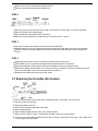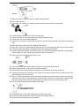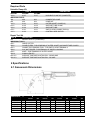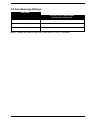
1
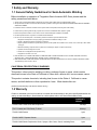
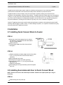
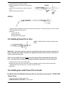
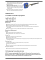
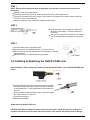
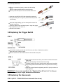
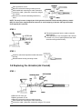
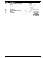
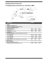
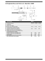
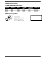
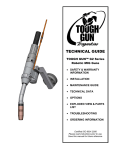
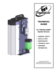
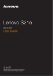
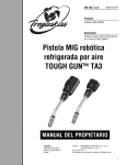
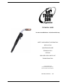
TECHNICAL GUIDE
For Air-Cooled MIG Guns - 350, 450 and 550 amp
SAFETY AND WARRANTY INFORMATION
INSTALLATION
MAINTENANCE GUIDE
TECHNICAL DATA
OPTIONS
EXPLODED VIEW & PARTS LIST
TROUBLESHOOTING
Certified ISO 9001:2000
Please read instructions prior to use.
Save this manual for future reference.
M001 REV E (Full Manual)
07/10
1 / 19
Table Of Contents
TOUGH GUN 350, 450, 550 amp Air-Cooled MIG Guns ......................... 1
1 Safety and Warranty .................................................. 3
1.1 General Safety Guidelines for Semi-Automatic Welding ........................... 3
1.2 Warranty ....................................................... 3
2 Installation ........................................................ 4
2.1 Installing Quick Connect Block to Feeder ................................... 4
2.2 Installing Semi-Automatic Gun to Quick Connect Block ........................... 4
2.3 Installing Power Pin to Gun ............................................ 5
2.4 Installing Gun with Power Pin to Feeder .................................... 5
3 Maintenance ....................................................... 6
3.1 Nozzle and Contact Tip System ......................................... 6
3.2 Replacing Conventional Liner .......................................... 6
3.3 Installing or Replacing the QUICK LOAD Liner ................................ 7
3.4 Replacing the Trigger Switch ........................................... 8
3.5 Replacing the Gooseneck ............................................. 8
3.6 Replacing the Unicable (Air-Cooled) ...................................... 9
3.7 Repairing the Unicable (Air-Cooled) ...................................... 10
4 Specifications ..................................................... 12
4.1 Gooseneck Dimensions ............................................. 12
4.2 Gun Amperage Ratings ............................................. 13
5 Options and Accessories .............................................. 14
5.1 Specialty and Optional Items - 350, 450, 550 amp Semi-Auto Air-Cooled ............... 14
5.2 Direct Power Pins ................................................. 14
5.3 Feeder Adaptors ................................................. 15
5.4 Control Plugs ................................................... 15
5.5 Dual Schedule Option .............................................. 15
5.6 Accessories .................................................... 15
6 Exploded View & Parts List ............................................ 17
6.1 Exploded View and Parts List - Front End - M001 ............................. 17
6.2 Exploded View and Parts List - Back End - M001 .............................. 18
7 Ordering Information ................................................ 19
7.1 Gun Standards Chart - M001 .......................................... 19
7.2 Contact Tregaskiss ................................................ 19
2 / 19
1 Safety and Warranty
1.1 General Safety Guidelines for Semi-Automatic Welding
Before installation or operation of Tregaskiss Semi-Automatic MIG Guns, please read the
safety precautions listed below.
1. Always wear a properly fitted welding helmet with the proper grade of filter plate and suitable welding gloves.
2. All exposed skin should be covered with flame resistant, protective clothing. DO NOT WEAR CLOTHING MADE FROM FLAMMABLE
SYNTHETIC FIBERS.
3. Protective screens or barriers should be used to protect others from spatter, flash and glare while welding.
4. Prevent fires by ensuring that hot slag or sparks do not contact combustible solids, liquids or gases.
5. Ensure that operator’s head is not too close to the arc and that adequate ventilation is available.
6. Constant repetitive motion may lead to cumulative trauma disorders.
7. Do not touch live electrical parts. The following should be checked to prevent electrical shock.
1. Equipment is adequate for the job, properly grounded and installed according to code.
2. Faulty or damaged equipment is repaired or replaced.
3. Proper operator maintenance is performed to prevent excess spatter accumulation in the nozzle, or the contact tip or other areas
of the gun.
4. Electrical insulating components are in place and not damaged. Repair or replace if necessary.
5. operator and surroundings are not wet
6. cables are not wrapped around operator’s body
7. equipment is off when not in use
8. CSA Standard W117.2 CODE FOR SAFETY IN WELDING AND CUTTING obtainable from the Canadian Standards Association,
Standards Sales, 178 Rexdale Boulevard, Rexdale, Ontario, Canada M9W 1R3.
9. ANSI Standard Z49.1 CODE FOR SAFETY IN WELDING AND CUTTING obtainable from the American National Standards Institute,
1430 Broadway, New York, NY 10018.
CALIFORNIA PROPOSITION 65 WARNING
This product, when used for welding or cutting, produces fumes or gases which contain
chemicals known to the State of California to cause birth defects and, in some cases, cancer.
This product contains chemicals, including lead, known to the State of California to cause
cancer, and birth defects or other reproductive harm. Wash hands after use.
(California Health & Safety Code Section 25249.5 at seq.)
1.2 Warranty
Product is warranted to be free from defects in material and workmanship for the period specified below after the
sale by an authorized Buyer. Should there be a defect please refer to our Return Merchandise Policy.
PRODUCT
WARRANTY
PERIOD
TOUGH GUN™ MIG Guns and Components
180 days
TGX™ Chassis and TGX Ready To Weld
90 days
TOUGH GUN Reamer
1 year
TOUGH GARD™ Spatter Cleaner
1 year
TOUGH GUN Robotic Peripherals: Clutch, Sprayer, Wire Cutter, Clutch, Insulating Discs,
1 year
3 / 19
and Robotic Arms
Low-Stress Robotic Unicables (LSR Unicables)
2 years
Tregaskiss reserves the right to repair, replace or refund the purchase price of non-conforming product.
Product found not defective will be returned to the Buyer after notification by Customer Service.
Tregaskiss makes no other warranty of any kind, expressed or implied, including, but not limited to the
warranties of merchantability or fitness for any purpose. Tregaskiss shall not be liable under any circumstances
to Buyer, or to any person who shall purchase from Buyer, for damages of any kind. Including, but not limited to
any, direct, indirect incidental or consequential damages or loss of production or loss of profits resulting from
any cause whatsoever, including, but not limited to, any delay, act, error or omission of Tregaskiss.
Genuine Tregaskiss parts must be used for safety and performance reasons or the warranty becomes invalid.
Warranty shall not apply if accident, abuse, or misuse damages a product, or if a product is modified in any way
except by authorized Tregaskiss personnel.
2 Installation
2.1 Installing Quick Connect Block to Feeder
STEP #1
Insert the correct feeder adaptor liner for desired
wire diameter (3 provided) flush with the threaded
end of the feeder adaptor.
Tighten setscrew.
Thread feeder adaptor into Quick Connect block
and tighten.
STEP #2
Position assembly into feeder adaptor and trim liner within
1/16” (1.6 mm) of the drive rolls and remove burrs if
necessary.
Secure assembly into feeder.
Thread gas hose nipple into feeder gas fitting.
Connect power cable to ½” (13 mm) power bolt with
appropriate lug.
Tighten all connections.
Feed welding wire through assembly by hand and tighten
drive rolls.
2.2 Installing Semi-Automatic Gun to Quick Connect Block
NOTE: Ensure correct liner and contact tip are utilized. Examine and replace power pin o-rings if
necessary.
STEP #1
Guide welding wire into power pin.
4 / 19
Insert power pin to shoulder of feeder.
Tighten thumbscrew (on Quick Connect Block)
securely.
Connect control plug lead to control housing on
gun.
Insert control plug into feeder.
STEP #2
With gun lying straightened, pull trigger and feed wire through gun. It may be necessary to remove contact
tip when feeding small wire sizes).
Recheck:
proper gas flow
drive roll pressure
voltage and wire feed speed
2.3 Installing Power Pin to Gun
NOTE: TOUGH GUN Semi-Automatic Rear Handle
Shown
IMPORTANT: The thread-in two-piece power pin incorporates a taper to seat and lock in the power pin
to the rear handle block. Make sure power pin is tightened in the block with a wrench to ensure pin is
secure and will not come loose.
NOTE: The rear handle and screws do not have to be removed when installing the two-piece power
pins. A unicable repair is needed when changing from 425 Euro assembly to a non-euro power pin.
Thread power pin into the rear handle block.
Tighten the power pin into the rear block using an adjustable wrench on the rear block and another
adjustable wrench on the power pin. Torque to 18 ft-lb (24.4 Nm).
Install liner.
2.4 Installing Gun with Power Pin to Feeder
For Most Power Pins (Bernard, Euro and Oxo are not direct connect pins) - TOUGH GUN
™Model Shown
Insert power pin to shoulder and secure.
SEMI-AUTOMATIC GUNS ONLY - Insert control
5 / 19
plug to control housing of gun and then to feeder.
Feed welding wire into power pin by hand and
tighten drive rolls.
WATER-COOLED GUNS ONLY - Securely clamp
blue hose on rear housing to Water Out on water
Cooled and red hose on rear housing to Water In
on water cooler.
On Lincoln feeders it is necessary to connect the
gas hose to the barbed fitting on the power pin.
3 Maintenance
3.1 Nozzle and Contact Tip System
IMPORTANT:
Gooseneck insulator MUST be in place before welding to properly insulate gooseneck armor
Check all parts to ensure that connections are tight before welding
The retaining head MUST be tightened with a 5/8” (16 mm) wrench to prevent the contact tip from
over-heating
DO NOT use pliers to remove or tighten the retaining head or scoring may result
Removal and Replacement
Nozzle
Pull slip-on nozzles off with a twisting motion
When installing the nozzle, ensure that it is fully seated
Contact Tip
Thread the contact tip into the retaining head
Torque to 30 in-lbs. (3.5 Nm)
The Tregaskiss Tip Tool - Part # 450-18 (for heavy-duty tips) or a pair of weld pliers are the optimal tools for
contact tip installation
Retaining Head
Thread retaining head onto gooseneck with a 5/8” (16 mm) wrench
Torque to 80 in-lbs. (9 Nm)
DO NOT use pliers to remove or tighten the heavy duty retaining head or scoring may result
Gooseneck Insulator
The gooseneck insulator is pressed onto the gooseneck by hand
3.2 Replacing Conventional Liner
NOTE: For guns equipped with “Direct Plug-Ins”, Bernard, or Euro-connector, the
procedure is the same. On Miller style guns, the liner is held captive by a guide cap,
which must be removed and replaced when changing the liner.
6 / 19
STEP 1
NOTE: Ensure power supply and water (if applicable) is off and gun is removed from feeder before
proceeding.
Remove nozzle, tip and gas diffuser.
If power pin uses a liner set screw, loosen the set screw using a 5/64” Allen wrench.
If power pin is thread-in liner type, using a 10 mm wrench, turn thread-in liner retainer counter-clockwise
until liner is free from the power pin.
With gun straightened, grip conduit liner with pliers and remove
STEP 2
Feed replacement liner through gun using short
strokes to avoid kinking. Twist liner clockwise if
necessary.
Using a 10 mm wrench, turn thread-in liner retainer
in a clockwise direction and tighten into the power
pin.
STEP 3
Push liner back into gun and hold in place.
Using liner gauge, trim conduit liner with ¾” (19 mm) stick out.
Remove any burr that may obstruct wire feed, especially on flat wire
type conduit liner.
Replace nozzle, tip and gas diffuser onto gooseneck.
3.3 Installing or Replacing the QUICK LOAD Liner
Initial installation – When replacing conventional liner with QUICK LOAD™ Liner -TOUGH GUN™MIG Gun
shown
Install the QUICK LOAD Liner from the back of the torch with
the retainer attached (using the same procedure as installing
a conventional liner). Future replacements will be done from
the front.
Push liner back into gun and hold in place. (Using liner gauge,
trim conduit liner to a ¾” stick out.
Feed wire through liner.
Reinstall consumables.
Replacement of QUICK LOAD Liner
HELPFUL HINT: Before cutting liner make a mark and pull it back out past the end of the welding wire
and then cut it and push the liner back into place securely. This will help with feeding the wire through
7 / 19
the contact tip afterwards.
Remove consumables (nozzle, contact tip and retaining
head).
Remove existing QUICK LOAD Liner from the gun.
Remove protective cap from the new QUICK LOAD Liner.
Insert the new QUICK LOAD Liner through the gooseneck
using the welding wire as a guide. (short strokes will prevent
from kinking).
Once liner stops feeding, give it an extra push to ensure it is
inserted completely
Push liner back into gun and hold in place. Using liner gauge,
trim conduit liner to a ¾” stick out.
Reinstall consumables
3.4 Replacing the Trigger Switch
STEP 1
Loosen both mounting screws with a 5/16” (8 mm) nut driver or flathead screwdriver.
Ease switch out of switch housing.
Remove switch from switch lead connectors with needle nose pliers.
STEP 2
Push switch lead connectors firmly onto switch terminals with needle
nose pliers.
Depress switch plunger and nest back into housing.
Fit switch housing into nest on handle (switch leads must lie parallel).
Align housing holes with threaded holes in body and insert mounting
screws.
Start both screws first before tightening with 5/16” (8 mm) nut driver to
even alignment.
IMPORTANT: Use screws specified in the "Exploded View & Parts List" for this gun
model to ensure proper length, hardness and tolerance.
3.5 Replacing the Gooseneck
STEP 1 (NOTE: TOUGH GUN Semi-Automatic Gun shown)
8 / 19
Place gooseneck in vise.
Remove both switch housing mounting screws.
Slide handle back exposing the cable connection.
Loosen the cable / gooseneck connection using an
7/8” wrench.
Remove from vise and unthread gooseneck by
hand.
NOTE: The body is now an integral part of the gooseneck and the handle mounting holes are metric
(M5). Use the screws supplied with the new neck to avoid stripping of threads. Old style 407 bodies
used Imperial (U.S.) threads.
STEP 2
Thread the gooseneck into the cable connection
(hand tighten).
Place gooseneck in vise and tighten with a wrench
to within 1/8” (3.2 mm) spacing between the cable
connection and gooseneck body.
STEP 3
Install the switch and reposition handle and switch
housing.
Reinstall switch housing mounting screws
3.6 Replacing the Unicable (Air-Cooled)
STEP 1
Remove liner from gun.
Mount gooseneck in vise.
Remove both switch housing mounting screws.
Slide handle back exposing the cable connection.
Loosen the cable / gooseneck connection using an 7/8” wrench.
9 / 19
Remove from vise and unthread gooseneck by hand.
Remove switch from leads and slide handle back.
STEP 2
Remove power pin from power pin block using a 5/8” wrench on the pin and a 1” wrench on the block
Remove both terminal housing screws
Slide handle back exposing the cable connection
Remove power pin block from unicable using a 7/8” wrench and a 1” wrench
STEP 3
Take new unicable and starting from the front install the gooseneck
Slide the handle up over the connection ensuring that the switch leads slide out the hole on the handle
Install the switch to the switch leads and secure the handle and switch housing in place using the two
screws
STEP 4
Reinstall power pin block to rear of unicable and thread power pin into block
Slide handle up over connection ensuring that switch leads can slide out of the hole
Plug switch leads into terminal housing and secure handle and housing using two screws
Reinstall liner (Make sure that there is ¾” of the liner sticking out past the end of the gooseneck when the
torch is fully extended, if there is not a new liner will be required.)
Reinstall consumables and reconnect to wire feeder
3.7 Repairing the Unicable (Air-Cooled)
1.
2.
3.
4.
5.
6.
7.
8.
Remove consumables (may include Nozzle, Retaining Head or Tip Holder, and Contact Tip).
Remove the liner from the gun.
Mount gooseneck in the vice.
Remove switch housing and switch from leads.
Move the handle back.
Bend unicable behind connector cone. Cut unicable at bend.
Slide two large “oetiker” clamps 1.5 ft down the unicable (required for crimping later).
From your cut, (end of cable) measure 8” back and cut away the outer jacket of the cable. **Be careful not to
cut the copper wiring and leads**
10 / 19
9. Slide outer jacket forward to expose the copper wiring and leads.
10. Pull out the lead wires.
11. From the 8” cut, measure 3 ½” towards the front of the torch and cut off the excess cable.
12.
13.
14.
15.
16.
17.
18.
19.
20.
21.
22.
23.
24.
25.
26.
Fan back copper and remove 3/4” of the inner gas tube.
Take the old liner you just removed and cut it to approximately 2 ft long.
Thread cone onto vice mounted gooseneck.
Insert the 2 ft. of old liner into the gooseneck from the front end of the gooseneck, then slide on the support
tube.
Slide small Oetiker clamp over top of inner gas tube (Hytrel).
Using the 2’ old liner as a guide, slide the inner gas tube over the support tube and up to the cone shoulder.
Crimp the support tube clamp. Crimp between the black and white switch leads.
Position copper wires between roll marked numbers on cone and first step before threads. Crimp the large
oetiker clamps 1/4” and 1” behind the outer jacket at the front of the torch.
Remove the inner gas tube (Hytrel) from the cone.
Fan out the copper and bring the copper around the inner gas tube (Hytrel) evenly.
Slide the inner gas tube on the Cone up to the cone shoulder.
Fan the copper evenly around the inner gas tube up to the shoulder of the Cone Connector.
Thread the Cone Nut onto Connector Cone. Torque the Cone Nut to 30 ft-lbs (There should be about a 1/8”
gap between the cone and cone nut).
Using ¾” Teflon electrical tape, wrap up the copper and spare switch leads neatly. Loop the 2 switch leads
that will be used. This is to ensure that there is enough slack in the wire for gun articulation. Make sure that
the control wire sheath is over switch leads where the cone and cone nut are to prevent any wear.
Pull up the handle and feed switch leads through handle.
27. Strip leads about 1/8” back and crimp switch terminals to open leads.
28. Connect the leads to the switch and lay the switch back into the housing.
29. Screw the switch housing back onto the handle.
11 / 19
Required Parts
Unicable Clamp Kit
PART #
350 AMP
450 AMP
313-8
413-7
INDIVIDUAL PARTS
308
408
409
409
313-3
513-1
413-5
413-5
413-4
413-4
412-1
412-1
412-3
412-3
DESCRIPTION
550 AMP
513-7
UNICABLE CLAMP KIT (COMPLETE)
408
509
523-1
413-5
413-4
412-1
412-3
CONNECTOR CONE
CONE NUT
OUTER JACKET CLAMPS (2)
SUPPORT TUBE CLAMP
SUPPORT TUBE
SWITCH LEAD CONNECTORS (2)
CONTROL WIRE SHEATH
Repair Tool Kit
PART #
DESCRIPTION
450
REPAIR TOOL KIT (COMPLETE)
INDIVIDUAL TOOLS
450-1
CABLE CUTTER
450-2
CLAMP PLIERS - FOR CRIMPING OF OUTER JACKET AND INNER TUBE CLAMPS
450-3
CONNECTOR CRIMPING TOOL - FOR SWITCH LEAD TERMINALS
450-4
5/16" NUT DRIVER - FOR REMOVAL OF SWITCH HOUSING
450-5
KNIFE - FOR TRIMMING OF OUTER JACKET
450-21
5 MM ALLEN KEY
450-13-2
SUPPORT TUBE INSTALLATION PIN – 350/450 AMP
450-13-3
SUPPORT TUBE INSTALLATION PIN – 550 AMP
4 Specifications
4.1 Gooseneck Dimensions
GOOSENECK
305-60
405-45
405-60
405-180
505-45
505-60
A
60°
45°
60°
180°
45°
60°
B
C
D
E
INCHES
MM
INCHES
MM
INCHES
MM
INCHES
MM
4.10
5.19
4.98
7.35
7.23
6.04
105
132
127
187
184
153
4.00
3.55
4.78
--3.87
5.30
103
90
121
--98
135
2.00
3.00
3.00
--4.00
4.00
51
76
76
--102
102
1.90
1.90
1.90
1.90
1.90
1.90
48
48
48
48
48
48
12 / 19
4.2 Gun Amperage Ratings
GUN MODEL
350 amp
60% DUTY CYCLE - MIXED GASES
OR 100% DUTY CYCLE - CO2
350 amp
450 amp
450 amp
550 amp
550 amp
NOTE: Ratings are based on tests that comply with IEC 60974-7 standards.
13 / 19
5 Options and Accessories
5.1 Specialty and Optional Items - 350, 450, 550 amp Semi-Auto
Air-Cooled
ITEM
1
2
3
4
5
6
PART #
401-10-87
401-21
401-41-50
404-41
401-42-50
401-26-62
7
401-26-75
8
9
10
402-26
430-3
656-1
DESCRIPTION
SPOT NOZZLE (BRASS)
FLUX CORE NOZZLE (GASLESS)
EXTENDED REACH NOZZLE - 3.5" (88.9 MM)
EXTENDED REACH GAS DIFFUSER
HIGH ACCESS NOZZLE (BOTTLE-NECKED)
WATER-COOLED NOZZLE - FIXED HOSE SYSTEM 5/8" (15.9 MM) FOR 5/16" (7.9 MM)
TIP RECESS
WATER-COOLED NOZZLE - FIXED HOSE SYSTEM 3/4" (19 MM) FOR 5/16" (7.9 MM)
TIP RECESS
GOOSENECK INSULATOR USED WITH 401-26-62 & 401-26-75
WATER HOSE ONLY - 15' (4.6 M)
HOSE CLAMP
5.2 Direct Power Pins
NOTE: Euro MIG guns will require unicable repair and a new rear handle assembly to use direct power
pins.
PART #
214
414-11-2
214-6-116
214-6-332
214-116
214-332
214-9
414-116
414-332
414-9
214-12
414-12-2
DESCRIPTION
TREGASKISS CONVENTIONAL
POWER PIN
USE ON FEEDERS
TREGASKISS QUICK CONNECT BLOCK, HOBART
2000 SERIES FEEDERS, TWECO #4 RECEPTACLE
BODY PART #TAK-1
O-RING - FOR MILLER POWER PINS MILLERMATIC 200 & 250, S21E & S22 SERIES, 52 &
54 SERIES, 60 SERIES
MILLER POWER PIN - FOR .035" MILLERMATIC 200 & 250, S21E & S22 SERIES, 52 &
1/16" WIRE
54 SERIES, 60 SERIES
MILLER POWER PIN - FOR 5/64" MILLERMATIC 200 & 250, S21E & S22 SERIES, 52 &
3/32" WIRE
54 SERIES, 60 SERIES
GUIDE CAP ONLY - FOR 214-6-116
(NEW STYLE)
GUIDE CAP ONLY - FOR 214-6-332
(NEW STYLE)
GUIDE CAP ONLY – FOR ALUMINUM
LINER (NEW STYLE)
GUIDE CAP ONLY - FOR 214-6-116
(OLD STYLE)
GUIDE CAP ONLY - FOR 214-6-332
(OLD STYLE)
GUIDE CAP ONLY – FOR ALUMINUM
LINER (OLD STYLE)
TWECO #5 STYLE POWER PIN
ALL FEEDERS SET UP WITH TWECO #5
O-RING - FOR TWECO° #5 STYLE
RECEPTACLE BODY PART #6TAK-1
14 / 19
214-2
414-21
214-13
POWER PIN
LINCOLN POWER PIN
ESAB (Non Euro)
PANASONIC
LINCOLN LN7, 8 & 9, LN25 SUITCASE, LN22,NA2
A-10
5.3 Feeder Adaptors
To be used with 417 (Tweco #4), 417-50 (Euro) & 417-60 (Tweco #5) Quick Connect Block
PART #
418-1
418-3
418-4
418-5
418-6
418-7
418-8
418-9
418-10
418-14
418-21
418-27
418-29
418-35
USE ON FEEDERS
AIRCO
ESAB (NON EURO STYLE) AND HOBART BETA MIG
HOBART 27
LINCOLN LN4, LN5, LINDE SWM 31, 3A & 32A
LINCOLN LN7, 8 & 9, LN 25 SUITCASE, LN22
LINDE SWM-14
LINDE 35 SWM-23
MILLER 10A, 30A (MILLERMATIC 35S FEEDER)
MILLER 52E, 54E, S21, S22 SERIES AND MILLERMATIC 200 & 250, 60 SERIES
OTC
GILLILAND
PANASONIC
TWECO #5 PIN
KOBELCO
5.4 Control Plugs
PART #
419-1
419-2
419-4
419-5
419-6
419-7
419-8
419-10
419-11
419-12
DESCRIPTION
AIRCO
HOBART
MILLER (52E, 54E)
WESTINGHOUSE
LINCOLN (LN7, 8, 9) NA2
MILLER (10E, 30E) & LINDE (SWM-35)
DIPSTICK 160,200, HOBART HANDLER, LINCOLN SP-100
DUAL SCHEDULE MILLER
LINCOLN DUAL SCHEDULE
OXOMATIC
5.5 Dual Schedule Option
Two Position Switch Style
PART #
DESCRIPTION
411-11
DUAL SCHEDULE TWO-POSITION SWITCH HOUSING ONLY
Toggle Switch Style
PART #
DESCRIPTION
411-12
DUAL SCHEDULE SWITCH HOUSING - COMPLETE W/TOGGLE SWITCH
411-13
DUAL SCHEDULE LOCK-ON TRIGGER HOUSING
5.6 Accessories
15 / 19
PART #
411-20
DESCRIPTION
SWITCH HOUSING WITH EXTENDED
LEVER
411-4
SWITCH HOUSING WITH LOCK ON
TRIGGER
421
421-1
HEAT SHIELD
SHIELD MOUNTING SCREW (NOT
SHOWN)
GUN HANGER
422
16 / 19
6 Exploded View & Parts List
6.1 Exploded View and Parts List - Front End - M001
DESCRIPTION
1
2
3
4
5
6
7
8
9
10
11
12
13
14
NOZZLE
TOUGH LOCK CONTACT TIP
TOUGH LOCK HEAVY-DUTYGAS DIFFUSER
TOUGH LOCK RETAINING HEAD
NOZZLE RETAINER
RETAINING RING ONLY
O-RING ONLY
GOOSENECK INSULATOR
GOOSENECK
UNICABLE ASSEMBLY (Includes handle/spring assembly)
10' (3 m) SERVICE
12' (4 m) SERVICE
15' (5 m) SERVICE
20' (6 m) SERVICE
25' (8 m) SERVICE
HANDLE/SPRING GUARD ASSEMBLY-FRONT AND REAR
SWITCH ONLY
SWITCH OPTIONS
MOUNTING SCREWS (Metric M5)
UNICABLE REPAIR KIT (Includes parts 15-21)
PART #
350 amp
450 amp
550 amp
402-3
454-1-2
402-6
402-11
402-3
454-1-2
402-6
402-11
402-3
454-1-2
402-6
402-11
313-10
313-12
313-15
313-20
313-25
410
411-1
413-10
413-12
413-15
413-20
413-25
410
411-1
513-10
513-12
513-15
513-20
513-25
410
411-1
411-3M
313-8
411-3M
413-7
411-3M
513-7
17 / 19
6.2 Exploded View and Parts List - Back End - M001
DESCRIPTION
22 POWER PIN BLOCK
23 POWER PIN
24 QUICK LOAD LINER
24A QUICK LOAD LINER RETAINER
25 CONVENTIONAL THREAD-IN LINER
26 CONTROL HOUSING WITH SCREWS
27 FEEDER ADAPTOR (SOLD SEPARATELY)
28 FEEDER ADAPTOR PIN (SOLD SEPARATELY)
ACCESSORIES (NOT SHOWN)
SPRING GUARD FOR 60 DEGREE NECK
SPRING GUARD FOR 45 DEGREE NECK
GUN HANGER
HEAT SHIELD (SOLD WITH GUN HANGER
HEAT SHIELD MOUTING SCREWS
PART #
350 amp
414-400
450 amp
414-400
550 amp
414-400
415-26
415-26
415-26
416-5
416-5
416-5
NA
NA
NA
NA
NA
406-1
406-2
422
421
421-1
506-1
NA
NA
NA
NA
18 / 19
7 Ordering Information
7.1 Gun Standards Chart - M001
GUN MODEL
GOOSENECK
NOZZLE
350 amp
450 amp
550 amp
305-60
405-60
505-60
401-6-62
401-6-62
401-5-75
RETAINING
HEAD
404-20
404-20
404-20
GOOSENECK
INSULATOR
402-11
402-11
402-11
CONTACT TIPS
403-20-XX
403-20-XX
403-20-XX
7.2 Contact Tregaskiss
DISTRIBUTED BY:
19 / 19