1
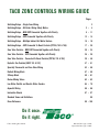
TACO ZONE CONTROLS WIRING GUIDE
Pages
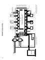
Switching Relays – Single Zone Wiring
Switching Relays – Oil Boiler Wiring Safety Notice
Switching Relays – NON EXP Connected Together with Priority
2– 2
23 – 4
5 – 11
Switching Relays – EXP Connected Together with Priority
12 – 14
Switching Relays – Multiple Indirect Hot Water Heaters
15 – 16
Switching Relays – EXP Connected To Reset Controls (PC700, 702 & 705)
17 – 28
Zone Valve Controls – NON EXP Connected Together with Priority
29 – 34
Zone Valve Controls – EXP Connected Together with Priority
35 – 38
Zone Valve Controls – Connected To Reset Controls (PC700, 702 & 705)
39 – 46
Hydro Air Fan Controls (HAFC 101 & 201)
47 – 51
Specialty Thermostat and Zone Valve Wiring
52 – 56
Radiant Mixing Block
57 – 58
X-Pump Block
59 – 61
iSeries Mixing Valves
62 – 63
Low Water Cutoffs and Electric Water Feeders
64 – 79
Aquastat Wiring
80 – 86
Instruction Sheets
87 – 97
Standard Terms and Definitions
Cross Reference
– 98
99 – 100
Do it once.
Do it right.
© Taco Catalog No. 100-9.0
Effective Date: July 1, 2010
Supersedes Date: July 1, 2007
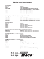
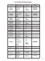
TACO Zone Control Product Information
Switching Relays
Product No.
SR501
SR501-845RP
SR502
SR503
SR504
SR506
Description
1 Zone Switching Relay
1 Zone Switching Relay Replacement PC Board for
Honeywell R845, RA89A, RA832 or Comparable Relay
2 Zone Switching Relay with Priority
3 Zone Switching Relay with Priority
4 Zone Switching Relay with Priority
6 Zone Switching Relay with Priority
Switching Relays with PowerPort Options and Expandable to 20 Zones
Product No.
Description
SR501-EXP
1 Zone Switching Relay
SR503-EXP
3 Zone Switching Relay with Priority and 3 PowerPorts
SR504-EXP
4 Zone Switching Relay with Priority and 3 PowerPorts
SR506-EXP
6 Zone Switching Relay with Priority and 3 PowerPorts
Zone Valve Controls
Product No.
ZVC403
ZVC404
ZVC405
ZVC406
Description
3 Zone Valve
4 Zone Valve
5 Zone Valve
6 Zone Valve
Control
Control with Priority
Control
Control with Priority
Zone Valve Controls with PowerPort Options and Expandable to 20 Zones
Product No.
Description
ZVC404-EXP
4 Zone Valve Control with Priority and 2 PowerPorts
ZVC406-EXP
6 Zone Valve Control with Priority and 2 PowerPorts
Plug-In PowerPort Cards (For use with all -EXP controls)
Product No.
Description
PC600
Post Purge Timer Plug-In Card
PC605
Priority Protection Plug-In Card
PC610
Universal Timer/Pump Exercise Plug-In Card
Add-On Power Controls (For use with all -EXP controls)
Product No.
Description
PC700
Boiler Reset Control
PC702
2-Stage Boiler Reset Control
PC705
Variable Speed Pump Injection Mixing Control
Fan Controls
Product No.
HAFC101
HAFC201
Description
Hydro Air Fan Control
Hydro Air Fan Control with Optional Time Delays
Do it once.
Do it right.
TO: 120 VAC
POWER
JUMPER
CIRCULATOR
TO: TT ON BOILER
TO: ZC
CIRCULATOR
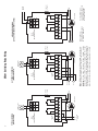
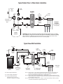
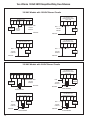
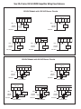
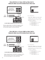
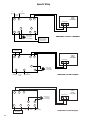
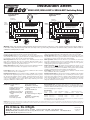
Note: When using Alternative Wiring diagram, the boiler operating control’s ZC terminal will see the load of the circulator(s).
Warning: When using Alternative Wiring diagram, wiring
instructions must be followed so power originates from the boiler
aquastat. Failure to follow these wiring instructions may result in
a secondary source of power being connected to the boiler that
may activate it under certain circumstances, causing injury or death.
TO: 120 VAC POWER
TO: ZR
4 4 6 6 5
N H 3 N/O
N/C N/C N/O
4 4 6 6 5
N H 3 N/O
N/C N/C N/O
T STAT
120 VAC
INPUT
POWER
T STAT
24
R W VAC
T T COM
POWER
SR501
1 ZONE
SWITCHING RELAY
T
T
24
R W VAC
T T COM
THERMOSTAT
THERMOSTAT
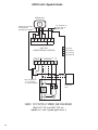
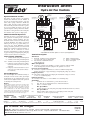
ALTERNATIVE WIRING
(TANKLESS COIL)
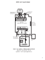
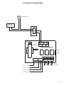
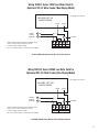
SR501 Switching Relay Wiring
120 VAC
INPUT
SR501
1 ZONE
SWITCHING RELAY
TYPICAL WIRING
(COLD START)
2
TO: 120 VAC POWER
REMOVE JUMPER.
DO NOT CONNECT POWER
TO N AND H TERMINALS.
N
H
24
R W VAC
T T COM
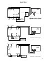
T STAT *
POWER *
24 VAC
SIGNAL
* T STAT LIGHT WILL GO
ON AND OFF WITH 24 VAC
SIGNAL. POWER LIGHT
WILL ALWAYS BE OFF.
CIRCULATOR
TO: TT ON BOILER
4 4 6 6 5
N H 3 N/O
N/C N/C N/O
SR501
1 ZONE
SWITCHING RELAY
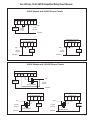
ALTERNATIVE WIRING
(24 VAC POWERED INPUT SIGNAL)
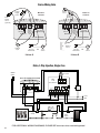
NOTE: No tankless coil priority.
3
(cont.)
L1
(HOT)
L2
THERMOSTATS
(NEUTRAL)
CIRCUIT
BREAKER
THERMOSTAT
ZONE 4
PRIORITY
ON
OFF
SR 504
ZONE 1 ZONE 2 ZONE 3 ZONE 4
CUSTOMER
EMERGENCY
SWITCH
FOUR ZONE SWITCHING RELAY
WITH OPTIONAL PRIORITY
L1
POWER
ZONE 1
ZONE 2
ZONE 3
ZONE 4
THERMAL
FUSE
(FIROMATIC)
120V RELAY
24 VAC
POWER
X
X
ZC ZR
END
SWITCH
SERVICE
SWITCH
ZONE1 ZONE2
ZONE3
T
L2
T
HONEYWELL L8124
OR EQUAL
C1
B2
ZC
C2
ZR
B1
ZONE4 POWER
120 VOLT CIRCULATORS
CIRCULATOR
ON BOILER
(IF ATTACHED)
INPUT
FUSE 1 AMP
LINE VOLTAGE
OIL BURNER RELAY
LOW
WATER
CUTOFF
120 VAC INPUT
NOTE: Tankless coil has priority.
L1
(HOT)
L2
THERMOSTAT
(NEUTRAL)
CIRCUIT
BREAKER
THERMOSTAT
24 VAC
POWER
SR 503
ZONE 1 ZONE 2
CUSTOMER
EMERGENCY
SWITCH
ZONE 3
THREE ZONE SWITCHING RELAY
WITH OPTIONAL PRIORITY
FUSE 1 AMP
L1
THERMAL
FUSE
(FIROMATIC)
L2
C1
B2
N
SERVICE
SWITCH
P
ZC
H
X2
X1 ZR
ZONE1
ZONE2
C2
ZONE3
120 VOLT CIRCULATORS
CIRCULATOR
ON BOILER
(IF ATTACHED)
LINE VOLTAGE
OIL BURNER RELAY
LOW
WATER
CUTOFF
120 VAC INPUT
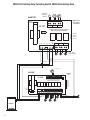
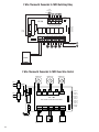
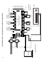
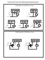
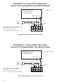
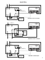
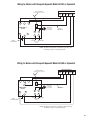
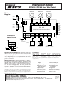
NOTE: The boiler operating control’s ZC terminal will see the load of the circulator(s).
4
T
T
HONEYWELL L8124
OR EQUAL
POWER
ZONE 1
ZONE 2
ZONE 3
ZC
ZR
B1
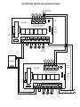
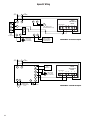
SR502/503 Switching Relay Controlling Another SR502/503 Switching Relay
AQUASTAT
ON DHW
HEATER
A
T
T
ZONE1
ZONE2
ZONE3
MASTER
24 VAC
POWER
PRIORITY ON
VIA JUMPER
PLACEMENT
SR 503
THREE ZONE SWITCHING RELAY
WITH OPTIONAL PRIORITY
FUSE 1 AMP
POWER
ZONE 1
ZONE 2
ZONE 3
N P ZC H
X2
X1 ZR ZONE1 ZONE2
ZONE3
JUMPER
120 VOLT
CIRCULATORS
N
120 VAC POWER
H
DHW
HEATER
CIRCULATOR
T
T
T
ZONE1
ZONE2
ZONE3
PRIORITY OFF
VIA JUMPER
PLACEMENT
SLAVE
24 VAC
POWER
SR 503
THREE ZONE SWITCHING RELAY
WITH OPTIONAL PRIORITY
FUSE 1 AMP
N P ZC H
POWER
ZONE 1
ZONE 2
ZONE 3
X2
X1 ZR ZONE1 ZONE2
ZONE3
JUMPER
BOILER
120 VOLT CIRCULATORS
TO: "TT" ON AQUASTAT CONTROL
5
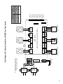
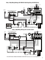
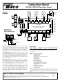
SR502/503 Switching Relay Controlling Another SR504/506 Switching Relay
AQUASTAT
ON DHW
HEATER
T
A
T
MASTER
PRIORITY ON
VIA JUMPER
PLACEMENT
24 VAC
POWER
SR 503
ZONE1
ZONE2
ZONE3
THREE ZONE SWITCHING RELAY
WITH OPTIONAL PRIORITY
FUSE 1 AMP
POWER
ZONE 1
ZONE 2
ZONE 3
N P ZC H
X2
X1 ZR ZONE1 ZONE2
ZONE3
JUMPERS
120 VOLT
CIRCULATORS
THERMOSTATS
T
SLAVE
SR 506
ZONE1 ZONE2 ZONE3 ZONE4 ZONE5 ZONE6
ZONE 6
PRIORITY
ON
SIX ZONE SWITCHING RELAY
WITH OPTIONAL PRIORITY
120V RELAY
24 VAC
POWER
X
X
END
SWITCH
PRIORITY
OFF
OFF
POWER
ZONE 1
ZONE 2
ZONE 3
ZONE 4
ZONE 5
ZONE 6
ZC ZR
ZONE1 ZONE2 ZONE3 ZONE4 ZONE5 ZONE6
120 VOLT CIRCULATORS
POWER
INPUT
FUSE 1 AMP
REMOVE
JUMPER
TO: "TT" ON BOILER
BOILER
6
120 VAC INPUT
H
N
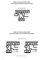
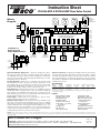
Two SR504/506 Switching Relays Connected Together
AQUASTAT ON
DHW HEATER
A
T
T
T
ZONE 4
PRIORITY
ON
OFF
SR 504
PRIORITY
ON
ZONE 1 ZONE 2 ZONE 3 ZONE 4
FOUR ZONE SWITCHING RELAY
WITH OPTIONAL PRIORITY
POWER
ZONE 1
ZONE 2
ZONE 3
ZONE 4
120V RELAY
24 VAC
POWER
X
X
ZC ZR
END
SWITCH
ZONE1 ZONE2
ZONE3
ZONE4 POWER
INPUT
120 VOLT CIRCULATORS
FUSE 1 AMP
120 VAC INPUT
JUMPER
DHW
HEATER
CIRCULATOR
T
BOILER
SR 504
T
T
ZONE 4
PRIORITY
ON
OFF
PRIORITY
ON
ZONE 1 ZONE 2 ZONE 3 ZONE 4
FOUR ZONE SWITCHING RELAY
WITH OPTIONAL PRIORITY
POWER
ZONE 1
ZONE 2
ZONE 3
ZONE 4
120V RELAY
24 VAC
POWER
X
X
ZC ZR
END
SWITCH
ZONE1 ZONE2
ZONE3
ZONE4 POWER
120 VOLT CIRCULATORS
INPUT
FUSE 1 AMP
H
120 VAC INPUT
JUMPER
N
TO: "TT" ON BOILER
OUTPUT
NOT
USED
7
Priority Zoning Circulator Controlling SR504/506 Switching Relay
MASTER
PRIORITY
ON
PRIORITY ZONING CIRCULATOR
PRIORITY
OFF
THERMOSTAT
2
1
BOILER
4
3
ON
PRIORITY
POWER IN
PR-IN PR-OUT LIVE NEUT
120 VAC INPUT
A
AQUASTAT ON
DHW HEATER
THERMOSTATS
T
PRIORITY
OFF
SLAVE
SR 506
ZONE1 ZONE2 ZONE3 ZONE4 ZONE5 ZONE6
ZONE 6
PRIORITY
ON
SIX ZONE SWITCHING RELAY
WITH OPTIONAL PRIORITY
120V RELAY
24 VAC
POWER
X
X
END
SWITCH
OFF
POWER
ZONE 1
ZONE 2
ZONE 3
ZONE 4
ZONE 5
ZONE 6
ZC ZR
ZONE1 ZONE2 ZONE3 ZONE4 ZONE5 ZONE6
120 VOLT CIRCULATORS
POWER
INPUT
FUSE 1 AMP
REMOVE
JUMPER
TO: "TT" ON BOILER
BOILER
8
120 VAC INPUT
H
N
9
BOILER
FUSE 1 AMP
SLAVE
24 VAC
POWER
X
A
T
T
ZONE 4
PRIORITY
ON
OFF
INPUT
ZONE4 POWER
120 VOLT CIRCULATORS
ZONE3
FOUR ZONE SWITCHING RELAY
WITH OPTIONAL PRIORITY
ZONE 1 ZONE 2 ZONE 3 ZONE 4
T
ZONE1 ZONE2
TO: "TT" ON BOILER
REMOVE
JUMPER
ZC ZR
END
SWITCH
X
120V RELAY
SR 504
T
AQUASTAT ON
DHW HEATER
POWER
ZONE 1
ZONE 2
ZONE 3
ZONE 4
PRIORITY
OFF
THERMOSTAT
2
1
BOILER
4
3
FUSE 1 AMP
SLAVE
PRIORITY
POWER IN
PR-IN PR-OUT LIVE NEUT
OFF
ON
X
X
T
T
T
ZONE3
ZONE 4
PRIORITY
ON
OFF
INPUT
ZONE4 POWER
120 VOLT CIRCULATORS
ZONE1 ZONE2
FOUR ZONE SWITCHING RELAY
WITH OPTIONAL PRIORITY
ZONE 1 ZONE 2 ZONE 3 ZONE 4
T
PRIORITY
ON
REMOVE
JUMPER
ZC ZR
END
SWITCH
120V RELAY
SR 504
120 VAC INPUT
PRIORITY
PRIORITY ZONING CIRCULATOR
MASTER
Priority Zoning Circulator Controlling 2 SR504/506 Switching Relays
24 VAC
POWER
120 VAC INPUT
POWER
ZONE 1
ZONE 2
ZONE 3
ZONE 4
PRIORITY
OFF
N
H
BOILER
FUSE 1 AMP
SLAVE
24 VAC
POWER
X
REMOVE
JUMPER
ZC ZR
T
T
ZONE 4
PRIORITY
ON
OFF
INPUT
ZONE4 POWER
120 VOLT CIRCULATORS
ZONE3
FOUR ZONE SWITCHING RELAY
WITH OPTIONAL PRIORITY
ZONE 1 ZONE 2 ZONE 3 ZONE 4
T
ZONE1 ZONE2
TO: "TT" ON BOILER
END
SWITCH
X
120V RELAY
SR 504
T
24 VAC
POWER
POWER
ZONE 1
ZONE 2
ZONE 3
ZONE 4
JUMPER
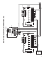
A
ZONE2
T
ZONE3
T
ZONE3
FUSE 1 AMP
SLAVE
X2
X1 ZR ZONE1 ZONE2
TWO ZONE SWITCHING RELAY
WITH OPTIONAL PRIORITY
ZONE1
N P ZC H
FUSE 1 AMP
SR 503
PRIORITY
OFF
MASTER
AQUASTAT ON
DHW HEATER
X
X
END
SWITCH
120V RELAY
REMOVE
JUMPER
ZC ZR
SR 504
POWER
ZONE 1
ZONE 2
ZONE 3
PRIORITY
ON
T
T
T
ZONE3
ZONE 4
PRIORITY
ON
OFF
120 VAC INPUT
INPUT
ZONE4 POWER
120 VOLT CIRCULATORS
ZONE1 ZONE2
FOUR ZONE SWITCHING RELAY
WITH OPTIONAL PRIORITY
ZONE 1 ZONE 2 ZONE 3 ZONE 4
T
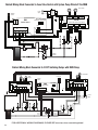
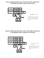
SR502/503 Switching Relay Controlling 2 SR504/506 Switching Relays
24 VAC
POWER
10
N
H
POWER
ZONE 1
ZONE 2
ZONE 3
ZONE 4
PRIORITY
OFF
11
BOILER
24 VAC
POWER
FUSE 1 AMP
SLAVE
X
TO: "TT" ON BOILER
REMOVE
JUMPER
ZC ZR
END
SWITCH
X
120V RELAY
SR 504
T
T
T
ZONE3
JUMPER
4 4 6 6 5
N H 3 N/O
N/C N/C N/O
ZONE 4
PRIORITY
ON
OFF
INPUT
POWER
ZONE 1
ZONE 2
ZONE 3
ZONE 4
PRIORITY OFF
DHW
CIRCULATOR
ZONE4 POWER
120 VOLT CIRCULATORS
ZONE1 ZONE2
FOUR ZONE SWITCHING RELAY
WITH OPTIONAL PRIORITY
ZONE 1 ZONE 2 ZONE 3 ZONE 4
T
FUSE 1 AMP
SLAVE
120 VAC INPUT
T STAT
POWER
24 VAC
POWER
DHW HEATER
AQUASTAT ON
24
R W VAC
T T COM
1 ZONE SWITCHING RELAY
SR501
MASTER
A
X
X
REMOVE
JUMPER
ZC ZR
END
SWITCH
120V RELAY
SR 504
T
T
T
ZONE3
120 VAC
INPUT
INPUT
POWER
ZONE 1
ZONE 2
ZONE 3
ZONE 4
PRIORITY OFF
ZONE 4
PRIORITY
ON
OFF
ZONE4 POWER
120 VOLT CIRCULATORS
ZONE1 ZONE2
FOUR ZONE SWITCHING RELAY
WITH OPTIONAL PRIORITY
ZONE 1 ZONE 2 ZONE 3 ZONE 4
T
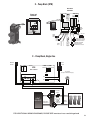
SR501 Switching Relay Controlling 2 SR504/506 Switching Relays
H
N
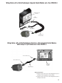
SR501-EXP Switching Relay Controlling Another SR504/506 Switching Relay
AQUASTAT ON
DHW HEATER
TO: "TT" ON BOILER
A
TO: OPTIONAL ZONE VALVE
OR iSeries MIXING VALVE
MASTER
MODE
POWER
CONTROLS
RESET
END
SWITCH
NORMAL
EXPANSION
X X 1 2 3 4
SLAVE
FUSE
1 AMP
THERMOSTAT
ZONE
VALVE
T/R T/W COM
1 2
SR 501-EXP
MASTER
POWER
T STAT
FUSE
5 AMP
N
H ZC ZR H
POWER
INPUT
H
120VAC 120VAC CIRC PRIORITY
INPUT OUTPUT OUTPUT OUTPUT
DHW CIRCULATOR
JUMPER
T
THERMOSTATS
SLAVE
SR 506
ZONE1 ZONE2 ZONE3 ZONE4 ZONE5 ZONE6
ZONE 6
PRIORITY
ON
SIX ZONE SWITCHING RELAY
WITH OPTIONAL PRIORITY
120V RELAY
24 VAC
X
POWER
X
END
SWITCH
PRIORITY
OFF
OFF
POWER
ZONE 1
ZONE 2
ZONE 3
ZONE 4
ZONE 5
ZONE 6
ZC ZR
ZONE1 ZONE2 ZONE3 ZONE4 ZONE5 ZONE6
120 VOLT CIRCULATORS
POWER
INPUT
FUSE 1 AMP
REMOVE
JUMPER
TO: "TT" ON BOILER
BOILER
12
120 VAC INPUT
H
N
MODE
H
N
MASTER
SLAVE
NORMAL
RESET
BOILER
120 VAC
INPUT
FUSE
1 AMP
POWER
CONTROLS
TO BOILER AQUASTAT RELAY
EXPANSION
1 2
ZONE
VALVE
H
24 VAC
SLAVE
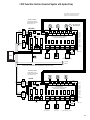
SYSTEM PUMP TURNS ON WHEN ANY ZONE VALVE OPENS
EXCEPT WHEN THE DHW HEATER (SR501-EXP) CALLS.
SYSTEM
PUMP
24 VAC
TO BOILER AQUASTAT RELAY
120 VAC
INPUT
BLACK
WHITE
120 VAC
INPUT
BLACK
WHITE
DHW
HEATER
CIRCULATOR
T STAT
POWER
TO: OPTIONAL ZONE VALVE
OR iSeries MIXING VALVE
BOILER TURNS ON WHEN ANY ZONE VALVE OPENS.
JUMPER
120VAC 120VAC CIRC PRIORITY
INPUT OUTPUT OUTPUT OUTPUT
H ZC ZR H
FUSE
5 AMP
POWER
INPUT
N
T/R T/W COM
THERMOSTAT
SR 501-EXP
X X 1 2 3 4
END
SWITCH
A
FACTORY
INSTALLED
TRANSFORMER
FACTORY
INSTALLED
TRANSFORMER
AQUASTAT ON
DHW HEATER
EXTRA
MAIN
END
END
SWITCH SWITCH
POWER IN
MASTER
MODE
NORMAL RESET
JUMPER
3&4
ZONE 1
1 2 3 4
2 WIRE ZONE VALVE
(NO END SWITCH)
N/O COM N/C
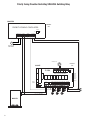
ZONE 6 RELAY
T T
ZONE 1
T T
ZONE 4
ZVC 406
T T
ZONE 3
T T
ZONE 5
T
1
2
3
ZONE 3
1 2 3 4
TACO
3 WIRE ZONE VALVE
ZONE 2
1 2 3 4
MOTOR
END
SWITCH
ZONE 5
1 2 3 4
PRIORITY
ZONE
SEE NOTE
VALVE 4
T STAT 5
VALVE 5
T STAT 6
VALVE 6
POWER
VALVE 2
T STAT 3
VALVE 3
T STAT 4
VALVE 1
T STAT 2
T STAT 1
Note: When a circulator is used on the
priority zone instead of a zone valve,
jumper 3 and 4 of the priority zone.
JUMPER
3&4
ZONE 6
1 2 3 4
ON
OFF
ZONE 6 PRIORITY
T T
ZONE 6
4 WIRE
ZONE VALVE
(POWER OPEN, SELF CLOSING)
ZONE 4
1 2 3 4
SIX ZONE ZONE VALVE CONTROL
WITH OPTIONAL PRIORITY
T T
ZONE 2
T
T
24 VAC
THERMOSTAT
THERMOSTAT
THERMOSTAT
SR501-EXP Switching Relay Controlling a ZVC404/406 Zone Valve Control
FUSE (7 AMP MAX)
13
2 Expandable Switching Relays Connected Together
SWITCH SETTINGS
Master/Slave: Slave
Reset/Normal: Normal
Priority Zone: Off
THERMOSTATS
T
SLAVE
SLAVE
PLUG-IN CARDS
MASTER
EXPANSION
POWER
CONTROL
INTERFACE
ZONE 4
PRIORITY
ON
OFF
1 2 3 4
ZONE 1 ZONE 2 ZONE 3 ZONE 4
SR504-EXP
FOUR ZONE SWITCHING RELAY
WITH OPTIONAL PRIORITY
RESET NORMAL
POWER
ZONE 1
ZONE 2
ZONE 3
ZONE 4
24 VAC
120V RELAY
SR 504-EXP
POWER
X
X
ZC ZR
END
SWITCH
ZONE1 ZONE2
ZONE3
ZONE4 POWER
120 VOLT CIRCULATORS
INPUT
FUSE 1 AMP
120 VAC INPUT
JUMPER
SWITCH SETTINGS
Master/Slave: Master
Reset/Normal: Normal
Priority Zone: On
THERMOSTATS
T
MASTER
PLUG-IN CARDS
SLAVE
POWER
CONTROL
INTERFACE
A
MASTER
1 2 3 4
ZONE1 ZONE2 ZONE3 ZONE4 ZONE5 ZONE6
EXPANSION
RESET
24 VAC
NORMAL
X
X
END
SWITCH
ZC ZR
ZONE 6
PRIORITY
ON
OFF
SR 506-EXP
SIX ZONE SWITCHING RELAY
WITH OPTIONAL PRIORITY
POWER
ZONE 1
ZONE 2
ZONE 3
ZONE 4
ZONE 5
ZONE 6
120V RELAY
POWER
AQUASTAT
ON DHW
HEATER
ZONE1 ZONE2 ZONE3 ZONE4 ZONE5 ZONE6
120 VOLT CIRCULATORS
POWER
INPUT
FUSE 1 AMP
H
JUMPER
N
TO: "TT" ON BOILER
BOILER
14
120 VAC INPUT
DHW
CIRCULATOR
15
FUSE 1 AMP
BOILER
24 VAC
POWER
SLAVE
X
TO: "TT" ON BOILER
JUMPER
ZC ZR
END
SWITCH
X
120V RELAY
SR 504
T
T
ZONE3
ZONE
NOT
USED
24 VAC
POWER
ZONE 4
PRIORITY
ON
OFF
INPUT
ZONE4 POWER
120 VOLT CIRCULATORS
ZONE1 ZONE2
FOUR ZONE SWITCHING RELAY
WITH OPTIONAL PRIORITY
ZONE 1 ZONE 2 ZONE 3 ZONE 4
T
MASTER
POWER
ZONE 1
ZONE 2
ZONE 3
ZONE 4
PRIORITY
ON
JUMPERS
A
ZONE2
A
ZONE3
POWER
24 V AC
ZONE3
FUSE 1 AMP
SLAVE
X2
X1 ZR ZONE1 ZONE2
TWO ZONE SWITCHING RELAY
WITH OPTIONAL PRIORITY
ZONE1
N P ZC H
FUSE 1 AMP
SR 502
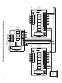
AQUASTATS ON
DHW HEATERS
X
X
JUMPER
ZC ZR
END
SWITCH
120V RELAY
SR 504
POWER
ZONE 1
ZONE 2
PRIORITY
OFF
T
T
ZONE3
ZONE 4
PRIORITY
ON
OFF
ZONE
NOT
USED
120 VAC INPUT
INPUT
ZONE4 POWER
120 VOLT CIRCULATORS
ZONE1 ZONE2
FOUR ZONE SWITCHING RELAY
WITH OPTIONAL PRIORITY
ZONE 1 ZONE 2 ZONE 3 ZONE 4
T
2 Indirect Water Heaters with Priority Connected to Standard Switching Relays
N
H
POWER
ZONE 1
ZONE 2
ZONE 3
ZONE 4
PRIORITY
ON
16
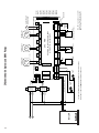
SWITCH SETTINGS
BOILER
24 VAC
POWER
POWER
CONTROL
INTERFACE
SLAVE
1 2 3 4
X
TO: "TT" ON BOILER
JUMPER
ZC ZR
END
SWITCH
X
120V RELAY
SR 504-EXP
ZONE 4
PRIORITY
ON
OFF
MASTER
ZONE
NOT
USED
INPUT
ZONE4 POWER
120 VOLT CIRCULATORS
ZONE3
FOUR ZONE SWITCHING RELAY
WITH OPTIONAL PRIORITY
SR504-EXP
ZONE 1 ZONE 2 ZONE 3 ZONE 4
T
ZONE1 ZONE2
PLUG-IN CARDS
RESET NORMAL
EXPANSION
FUSE 1 AMP
MASTER
Master/Slave: Master
Reset/Normal: Normal
Priority Zone: On
24 VAC
POWER
POWER
ZONE 1
ZONE 2
ZONE 3
ZONE 4
JUMPERS
ZONE2
A
ZONE3
AQUASTATS ON
DHW HEATERS
24 VAC
POWER
POWER
CONTROL
INTERFACE
SLAVE
FUSE 1 AMP
X
END
SWITCH
X
120V RELAY
JUMPER
ZC ZR
RESET NORMAL
EXPANSION
SWITCH SETTINGS
SR504-EXP
SR 504-EXP
120 VAC INPUT
INPUT
ZONE4 POWER
120 VOLT CIRCULATORS
ZONE3
FOUR ZONE SWITCHING RELAY
WITH OPTIONAL PRIORITY
ZONE 4
PRIORITY
ON
OFF
SLAVE
N
H
POWER
ZONE 1
ZONE 2
ZONE 3
ZONE 4
Master/Slave: Slave
Reset/Normal: Normal
Priority Zone: Off
ZONE 1 ZONE 2 ZONE 3 ZONE 4
T
ZONE1 ZONE2
PLUG-IN CARDS
POWER
ZONE 1
ZONE 2
PRIORITY
OFF
1 2 3 4
DHW
CIRCULATORS
ZONE3
MASTER
X2
X1 ZR ZONE1 ZONE2
TWO ZONE SWITCHING RELAY
WITH OPTIONAL PRIORITY
ZONE1
N P ZC H
FUSE 1 AMP
SR 502
A
2 Indirect Water Heaters with Priority Connected to EXP Switching Relays
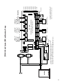
PC700 Boiler Reset Control Connected to SR501-EXP Switching Relay
OUTDOOR
SENSOR
SWITCH SETTINGS
Master/Slave: Master
Reset/Normal: Reset
PC700
THERMOSTAT
TO: "TT" ON BOILER
BOIL OUT
SEN SEN
T
ZONE
CONTROL
TO: OPTIONAL ZONE VALVE
OR iSeries MIXING VALVE
BOILER SENSOR
POWER
CONTROLS
MODE
RESET
NORMAL
SLAVE
END
SWITCH
EXPANSION
X X 1 2 3 4
FUSE
1 AMP
THERMOSTAT
ZONE
VALVE
T/R T/W COM
1 2
SR 501-EXP
MASTER
POWER
T STAT
FUSE
5 AMP
N
H ZC ZR H
POWER
INPUT
H
120VAC 120VAC CIRC PRIORITY
INPUT OUTPUT OUTPUT OUTPUT
BOILER
JUMPER
H
120 VAC INPUT
SYSTEM
CIRCULATOR
N
17
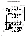
SR501-EXP and PC700 Boiler Reset Control Connected to an Existing Switching Relay
OUTDOOR
SENSOR
AQUASTAT ON
DHW HEATER
A
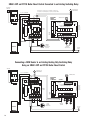
Note: If Zone Control comes on without a call for heat,
reverse Reset Override input (1 & 2) wires on SR501-EXP.
TO: "TT" ON BOILER
PC700
BOIL OUT
SEN SEN
EXISTING
ZONE
CONTROL
POWER
CONTROLS
ZONE
CONTROL
END
SWITCH
EXPANSION
X X 1 2 3 4
K1-A
BOILER SENSOR
FUSE
1 AMP
THERMOSTAT
RESET
OVERRIDE
T/R T/W COM
1 2
THERMOSTATS
T
MODE
RESET
ZONE 4
PRIORITY
ON
OFF
SR 504
ZONE1 ZONE2 ZONE3 ZONE4
MASTER
SR 501-EXP
SLAVE
K1
NORMAL
FOUR ZONE SWITCHING RELAY
WITH OPTIONAL PRIORITY
POWER
T STAT
K2
FUSE
5 AMP
K2-A
H ZC ZR H
POWER
INPUT
24 VAC
POWER
120V RELAY
K1-B
N
POWER
ZONE 1
ZONE 2
ZONE 3
ZONE 4
K2-A
H
120VAC 120VAC CIRC PRIORITY
INPUT OUTPUT OUTPUT OUTPUT
X
X
END
SWITCH
ZC ZR
ZONE1 ZONE2 ZONE3 ZONE4
120 VOLT CIRCULATORS
POWER
INPUT
FUSE 1 AMP
JUMPER
MASTER
JUMPER
PRIMARY
SYSTEM
CIRCULATOR
(Optional)
BOILER
DHW
HEATER
CIRCULATOR
120 VAC
INPUT
H
N
Connecting a DHW Heater to an Existing Heating Only Switching Relay
Using an SR501-EXP and PC700 Boiler Reset Control
OUTDOOR
SENSOR
A
AQUASTAT ON
DHW HEATER
TO: "TT" ON BOILER
T
PC700
BOIL OUT
SEN SEN
MASTER
EXISTING
ZONE
CONTROL
POWER
CONTROLS
ZONE
CONTROL
END
SWITCH
EXPANSION
X X 1 2 3 4
BOILER SENSOR
K1-A
FUSE
1 AMP
THERMOSTAT
RESET
OVERRIDE
T/R T/W COM
1 2
SLAVE
MODE
RESET
SR 504
ZONE1 ZONE2 ZONE3 ZONE4
MASTER
SR 501-EXP
SLAVE
K1
NORMAL
K2-A
K2-A
H
24 VAC
POWER
120V RELAY
H ZC ZR H
POWER
INPUT
POWER
ZONE 1
ZONE 2
ZONE 3
ZONE 4
POWER
T STAT
K2
K1-B
N
ZONE 4
PRIORITY
ON
OFF
FOUR ZONE SWITCHING RELAY
WITH OPTIONAL PRIORITY
FUSE
5 AMP
120VAC 120VAC CIRC PRIORITY
INPUT OUTPUT OUTPUT OUTPUT
X
X
END
SWITCH
ZC ZR
ZONE1 ZONE2 ZONE3 ZONE4
120 VOLT CIRCULATORS
POWER
INPUT
FUSE 1 AMP
JUMPER
BOILER
THERMOSTATS
DHW
HEATER
CIRCULATOR
REMOVE
JUMPER
120 VAC
INPUT
H
N
18
SR501-EXP and PC700 Boiler Reset Control Connected to an Existing Zone Valve Control
OUTDOOR
SENSOR
AQUASTAT ON
DHW HEATER
A
Note: If Zone Control comes on without a call for heat,
reverse Reset Override input (1 & 2) wires on SR501-EXP.
TO: "TT" ON BOILER
PC700
BOIL OUT
SEN SEN
120 VAC
INPUT
POWER
CONTROLS
ZONE
CONTROL
BLACK
END
SWITCH
EXPANSION
X X 1 2 3 4
K1-A
BOILER SENSOR
MASTER
RESET
OVERRIDE
T/R T/W COM
1 2
SR 501-EXP
SLAVE
K1
T
EXISTING
ZONE
CONTROL
24
VAC
T
T
24 VAC
ZONE 4
PRIORITY
MODE
MODE
NORMAL RESET
RESET
OFF
T T
ZONE 1
POWER IN
T T
ZONE 2
T T
ZONE 3
ON
T T
ZONE 4
T STAT 1
VALVE 1
T STAT 2
VALVE 2
T STAT 3
VALVE 3
T STAT 4
VALVE 4
POWER
NORMAL
FUSE
(3 AMP MAX)
FUSE
1 AMP
THERMOSTAT
FACTORY
INSTALLED
TRANSFORMER
THERMOSTATS
WHITE
POWER
T STAT
K2
ZVC 404
FOUR ZONE ZONE VALVE CONTROL
WITH OPTIONAL PRIORITY
FUSE
5 AMP
EXTRA
MAIN
END
END
SWITCH SWITCH
K1-B
N
K2-A
H ZC ZR H
POWER
INPUT
ZONE 1
1 2 3 4
N/O COM N/C
ZONE 4 RELAY
ZONE 2
1 2 3 4
ZONE 4
1 2 3 4
ZONE 3
1 2 3 4
K2-A
H
120VAC 120VAC CIRC PRIORITY
INPUT OUTPUT OUTPUT OUTPUT
JUMPER
3&4
JUMPER
3&4
SEE NOTE
PRIORITY
ZONE
1
2
3
2 WIRE ZONE VALVE
(NO END SWITCH)
JUMPER
TACO
3 WIRE ZONE VALVE
END
SWITCH
4 WIRE ZONE VALVE
(POWER OPEN,
SELF CLOSING)
ZONE VALVE SYSTEM
CIRCULATOR
PRIMARY
SYSTEM
CIRCULATOR
(Optional)
BOILER
MOTOR
Note: When a circulator is used on the
priority zone instead of a zone valve,
jumper 3 and 4 of the priority zone.
DHW HEATER
CIRCULATOR
H
N
120 VAC
INPUT
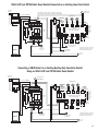
Connecting a DHW Heater to an Existing Heating Only Zone Valve Control
Using an SR501-EXP and PC700 Boiler Reset Control
OUTDOOR
SENSOR
A
AQUASTAT ON
DHW HEATER
TO: "TT" ON BOILER
PC700
BOIL OUT
SEN SEN
WHITE
MASTER
120 VAC
INPUT
POWER
CONTROLS
ZONE
CONTROL
BLACK
END
SWITCH
RESET
THERMOSTAT
OVERRIDE
EXPANSION
X X 1 2 3 4
K1-A
BOILER SENSOR
MASTER
T/R T/W COM
SLAVE
K1
T
EXISTING
ZONE
CONTROL
T
T
SLAVE
24 VAC
ZONE 4
PRIORITY
MODE
MODE
NORMAL RESET
RESET
OFF
1 2
SR 501-EXP
24
VAC
T T
ZONE 1
POWER IN
T T
ZONE 2
T T
ZONE 3
T T
ZONE 4
NORMAL
FUSE
(3 AMP MAX)
FUSE
1 AMP
FACTORY
INSTALLED
TRANSFORMER
THERMOSTATS
POWER
T STAT
K2
ZVC 404
FOUR ZONE ZONE VALVE CONTROL
WITH OPTIONAL PRIORITY
FUSE
5 AMP
EXTRA
MAIN
END
END
SWITCH SWITCH
K1-B
N
K2-A
H ZC ZR H
POWER
INPUT
N/O COM N/C
ZONE 4 RELAY
ZONE 1
1 2 3 4
ZONE 2
1 2 3 4
ZONE 3
1 2 3 4
ZONE 4
1 2 3 4
ON
T STAT 1
VALVE 1
T STAT 2
VALVE 2
T STAT 3
VALVE 3
T STAT 4
VALVE 4
POWER
K2-A
H
120VAC 120VAC CIRC PRIORITY
INPUT OUTPUT OUTPUT OUTPUT
JUMPER
3&4
JUMPER
3&4
SEE NOTE
PRIORITY
ZONE
1
2
3
2 WIRE ZONE VALVE
(NO END SWITCH)
JUMPER
DHW HEATER
CIRCULATOR
BOILER
TACO
3 WIRE ZONE VALVE
MOTOR
END
SWITCH
4 WIRE ZONE VALVE
(POWER OPEN,
SELF CLOSING)
Note: When a circulator is used on the
priority zone instead of a zone valve,
jumper 3 and 4 of the priority zone.
ZONE VALVE SYSTEM
CIRCULATOR
H
N
120 VAC
INPUT
19
SR501-EXP and PC700 Boiler Reset Control Connected to an Existing
Tankless Coil Boiler – Zoning with Circulators
OUTDOOR
SENSOR
THERMOSTATS
T
EXISTING
ZONE
CONTROL
POWER
CONTROLS
END
SWITCH
PC700
EXPANSION
X X 1 2 3 4
RESET
OVERRIDE
T/R T/W COM
1 2
MODE
RESET
ZONE 4
PRIORITY
ON
OFF
SR 504
ZONE1 ZONE2 ZONE3 ZONE4
K1-A
MASTER
FUSE
1 AMP
ZONE
CONTROL
SR 501-EXP
SLAVE
BOILER SENSOR
K1
NORMAL
FOUR ZONE SWITCHING RELAY
WITH OPTIONAL PRIORITY
120V RELAY
K1-B
N
K2-A
H ZC ZR H
POWER
INPUT
POWER
ZONE 1
ZONE 2
ZONE 3
ZONE 4
POWER
T STAT
K2
FUSE
5 AMP
24 VAC
POWER
BOIL OUT
SEN SEN
THERMOSTAT
K2-A
H
120VAC 120VAC CIRC PRIORITY
INPUT OUTPUT OUTPUT OUTPUT
X
X
END
SWITCH
ZC ZR
ZONE1 ZONE2 ZONE3 ZONE4
120 VOLT CIRCULATORS
POWER
INPUT
FUSE 1 AMP
JUMPER
PRIMARY
SYSTEM
CIRCULATOR
(Optional)
REMOVE
JUMPER
TO: "ZR" ON BOILER CONTROL
120 VAC
INPUT
TO: "ZC" ON BOILER CONTROL
H
BOILER
N
Boiler and Zone Control(s) need to be on same power supply (same circuit breaker).
SR501-EXP and PC700 Boiler Reset Control Connected to an Existing
Tankless Coil Boiler – Zoning with Zone Valves
OUTDOOR
SENSOR
MASTER
BLACK
POWER
CONTROLS
PC700
END
SWITCH
BOIL OUT
SEN SEN
EXPANSION
X X 1 2 3 4
ZONE
CONTROL
K1-A
BOILER SENSOR
T/R T/W COM
SLAVE
K1
T
EXISTING
ZONE
CONTROL
T
T
SLAVE
24 VAC
ZONE 4
PRIORITY
MODE
MODE
NORMAL RESET
RESET
OFF
1 2
SR 501-EXP
24
VAC
T T
ZONE 1
POWER IN
T T
ZONE 2
T T
ZONE 3
T T
ZONE 4
NORMAL
FUSE
(3 AMP MAX)
FUSE
1 AMP
MASTER
RESET
THERMOSTAT
OVERRIDE
FACTORY
INSTALLED
TRANSFORMER
THERMOSTATS
WHITE
120 VAC
INPUT
POWER
T STAT
K2
ZVC 404
FOUR ZONE ZONE VALVE CONTROL
WITH OPTIONAL PRIORITY
FUSE
5 AMP
EXTRA
MAIN
END
END
SWITCH SWITCH
K1-B
N
K2-A
H ZC ZR H
N/O COM N/C
ZONE 4 RELAY
ZONE 1
1 2 3 4
ZONE 2
1 2 3 4
ZONE 3
1 2 3 4
ZONE 4
1 2 3 4
ON
T STAT 1
VALVE 1
T STAT 2
VALVE 2
T STAT 3
VALVE 3
T STAT 4
VALVE 4
POWER
K2-A
H
POWER 120VAC 120VAC CIRC PRIORITY
INPUT OUTPUT OUTPUT OUTPUT
INPUT
JUMPER
3&4
JUMPER
3&4
SEE NOTE
PRIORITY
ZONE
1
2
3
TACO
2 WIRE ZONE VALVE
(NO END SWITCH) 3 WIRE ZONE VALVE
JUMPER
PRIMARY
SYSTEM
CIRCULATOR
(Optional)
TO: "ZR" ON BOILER CONTROL
ZONE VALVE SYSTEM
CIRCULATOR
MOTOR
END
SWITCH
4 WIRE ZONE VALVE
(POWER OPEN,
SELF CLOSING)
Note: When a circulator is used on the
priority zone instead of a zone valve,
jumper 3 and 4 of the priority zone.
TO: "ZC" ON BOILER CONTROL
BOILER
H
N
120 VAC
INPUT
Boiler and Zone Control(s) need to be on same power supply (same circuit breaker).
20
21
OUTDOOR
SENSOR
ZONE
CONTROL
BOILER
BOILER SENSOR
BOIL OUT
SEN SEN
PC700
24 VAC
POWER
POWER
CONTROL
INTERFACE
FUSE 1 AMP
MASTER
1234
X
JUMPER
ZC ZR
END
SWITCH
X
120V RELAY
RESET NORMAL
PLUG-IN CARDS
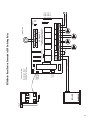
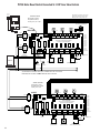
TO: "TT" ON BOILER
SLAVE
Master/Slave: Master
Reset/Normal: Reset
Priority Zone: On or Off
SWITCH SETTINGS
ZONE3
INPUT
N
H
POWER
ZONE 1
ZONE 2
ZONE 3
ZONE 4
120 VAC INPUT
ZONE 4
PRIORITY
ON
OFF
ZONE4 POWER
120 VOLT CIRCULATORS
ZONE1 ZONE2
FOUR ZONE SWITCHING RELAY
WITH OPTIONAL PRIORITY
SR 504-EXP
ZONE 1 ZONE 2 ZONE 3 ZONE 4
T
THERMOSTATS
PC700 Boiler Reset Control Connected to EXP Switching Relay
22
BOILER
#2
BOILER
#1
BOILER SENSOR
STAGE STAGE BOIL OUT ZONE
1
2 SEN SEN CONTROL
PC702
DHW
DEMAND
OUTDOOR
SENSOR
1234
FUSE 1 AMP
MASTER
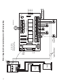
WIRING NEEDED ONLY IF
PRIORITY ZONE IS DHW
POWER
24 VAC
POWER
CONTROL
INTERFACE
SLAVE
X
JUMPER
ZC ZR
END
SWITCH
X
120V RELAY
RESET NORMAL
PLUG-IN CARDS
SYSTEM
CIRCULATOR
(OPTIONAL)
Master/Slave: Master
Reset/Normal: Normal
Priority Zone: On or Off
SWITCH SETTINGS
ZONE3
INPUT
N
H
POWER
ZONE 1
ZONE 2
ZONE 3
ZONE 4
120 VAC INPUT
ZONE 4
PRIORITY
ON
OFF
ZONE4 POWER
120 VOLT CIRCULATORS
ZONE1 ZONE2
FOUR ZONE SWITCHING RELAY
WITH OPTIONAL PRIORITY
SR 504-EXP
ZONE 1 ZONE 2 ZONE 3 ZONE 4
T
THERMOSTATS
PC702 2–Stage Boiler Reset Control Connected to EXP Switching Relay
23
OUTDOOR
SENSOR
ZONE
CONTROL
BOILER
BOILER SENSOR
SUPPLY SENSOR
BOIL SUP OUT
SEN SEN SEN
PC705-2
BLACK
BLUE
RED
FUSE 1 AMP
MASTER
1234
X
SYSTEM
CIRCULATOR
AND/OR BOILER
(SEE NOTE A)
END
SWITCH
X
120V RELAY
JUMPER
ZC ZR
RESET NORMAL
PLUG-IN CARDS
TO: "TT" ON BOILER
SLAVE
24 VAC
POWER
INJECTION
CIRCULATOR
SYSTEM
CIRCULATOR
AND/OR BOILER
(SEE NOTE B)
Master/Slave: Master
Reset/Normal: Reset
Priority Zone: On or Off
ZONE3
INPUT
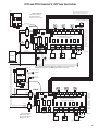
NOTE B: WHEN SYSTEM CIRCULATOR IS CONNECTED TO RED WIRE ON PC705-2, THE CIRCULATOR WILL OPERATE ONLY WHEN THERMOSTAT CALLS FOR HEAT
AND THE OUTDOOR TEMPERATURE IS BELOW THE WARM WEATHER SHUT DOWN (WWSD) TEMPERATURE. THE WWSD CAN BE ADJUSTED OR TURNED
OFF SO THAT THE CIRCULATOR IS NOT AFFECTED BY OUTDOOR TEMPERATURE.
H
N
POWER
ZONE 1
ZONE 2
ZONE 3
ZONE 4
120 VAC INPUT
ZONE 4
PRIORITY
ON
OFF
ZONE4 POWER
120 VOLT CIRCULATORS
ZONE1 ZONE2
FOUR ZONE SWITCHING RELAY
WITH OPTIONAL PRIORITY
SR 504-EXP
ZONE 1 ZONE 2 ZONE 3 ZONE 4
T
THERMOSTATS
NOTE A: WHEN SYSTEM CIRCULATOR IS CONNECTED TO ZR TERMINAL ON SWITCHING RELAY, THE MODE SWITCH MUST BE SET TO NORMAL.
THE PC705-2 WILL NOT RESET THE BOILER WHEN IN THE NORMAL MODE.
GREEN/GROUND
SWITCH SETTINGS
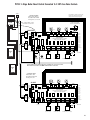
PC705 Variable Speed Pump Injection Control Connected to EXP Switching Relay
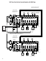
PC700 Boiler Reset Control Connected to 2 EXP Switching Relays
OUTDOOR
SENSOR
SWITCH SETTINGS
Master/Slave: Master
Reset/Normal: Reset
Priority Zone: On or Off
PC700
T
SLAVE
MASTER
PLUG-IN CARDS
ZONE 4
PRIORITY
ON
OFF
1 2 3 4
MASTER
ZONE
CONTROL
BOIL OUT
SEN SEN
THERMOSTATS
EXPANSION
POWER
CONTROL
INTERFACE
ZONE 1 ZONE 2 ZONE 3 ZONE 4
SR 504-EXP
BOILER SENSOR
FOUR ZONE SWITCHING RELAY
WITH OPTIONAL PRIORITY
RESET NORMAL
POWER
ZONE 1
ZONE 2
ZONE 3
ZONE 4
24 VAC
120V RELAY
POWER
X
X
ZC ZR
END
SWITCH
ZONE1 ZONE2
ZONE3
ZONE4 POWER
120 VOLT CIRCULATORS
INPUT
FUSE 1 AMP
TO: "TT" ON BOILER
JUMPER
120 VAC
INPUT
BOILER
SWITCH SETTINGS
THERMOSTATS
Master/Slave: Slave
Reset/Normal: Normal
Priority Zone: No Priority
T
SLAVE
MASTER
POWER
CONTROL
INTERFACE
SLAVE
PLUG-IN CARDS
1 2 3 4
EXPANSION
ZONE 1 ZONE 2 ZONE 3 ZONE 4
ZONE 4
PRIORITY
ON
OFF
SR 504-EXP
RESET NORMAL
FOUR ZONE SWITCHING RELAY
WITH OPTIONAL PRIORITY
POWER
ZONE 1
ZONE 2
ZONE 3
ZONE 4
120V RELAY
24 VAC
POWER
X
X
ZC ZR
END
SWITCH
ZONE1 ZONE2
ZONE3
ZONE4 POWER
120 VOLT CIRCULATORS
INPUT
FUSE 1 AMP
H
JUMPER
N
120 VAC INPUT
SYSTEM
CIRCULATOR
(OPTIONAL)
24
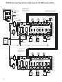
PC702 2–Stage Boiler Reset Control Connected to 2 EXP Switching Relays
OUTDOOR
SENSOR
SWITCH SETTINGS
Master/Slave: Master
Reset/Normal: Normal
Priority Zone: On or Off
DHW
DEMAND
THERMOSTATS
T
MASTER
PC702
SLAVE
STAGE STAGE BOIL OUT ZONE
1
2 SEN SEN CONTROL
PLUG-IN CARDS
ZONE 4
PRIORITY
ON
OFF
1 2 3 4
MASTER
EXPANSION
POWER
CONTROL
INTERFACE
ZONE 1 ZONE 2 ZONE 3 ZONE 4
SR 504-EXP
BOILER SENSOR
FOUR ZONE SWITCHING RELAY
WITH OPTIONAL PRIORITY
RESET NORMAL
POWER
ZONE 1
ZONE 2
ZONE 3
ZONE 4
24 VAC
120V RELAY
POWER
X
BOILER
#1
X
ZC ZR
END
SWITCH
ZONE1 ZONE2
ZONE3
ZONE4 POWER
120 VOLT CIRCULATORS
INPUT
FUSE 1 AMP
120 VAC INPUT
JUMPER
BOILER
#2
WIRING NEEDED ONLY IF
PRIORITY ZONE IS DHW
SWITCH SETTINGS
Master/Slave: Slave
Reset/Normal: Normal
Priority Zone: No Priority
THERMOSTATS
T
SLAVE
PLUG-IN CARDS
MASTER
POWER
CONTROL
INTERFACE
SLAVE
1 2 3 4
EXPANSION
ZONE 1 ZONE 2 ZONE 3 ZONE 4
ZONE 4
PRIORITY
ON
OFF
SR 504-EXP
RESET NORMAL
FOUR ZONE SWITCHING RELAY
WITH OPTIONAL PRIORITY
POWER
ZONE 1
ZONE 2
ZONE 3
ZONE 4
24 VAC
POWER
120V RELAY
X
X
ZC ZR
END
SWITCH
ZONE1 ZONE2
ZONE3
ZONE4 POWER
120 VOLT CIRCULATORS
INPUT
FUSE 1 AMP
H
JUMPER
N
120 VAC INPUT
SYSTEM
CIRCULATOR
(OPTIONAL)
25
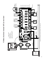
PC705 Variable Speed Pump Injection Control Connected to 2 EXP Switching Relays
SWITCH SETTINGS
Master/Slave: Master
Reset/Normal: Reset
Priority Zone: On or Off
OUTDOOR
SENSOR
THERMOSTATS
T
MASTER
GREEN/GROUND
(SEE NOTE B
ON PAGE 23)
SLAVE
PLUG-IN CARDS
1 2 3 4
MASTER
RED
EXPANSION
ZONE 1 ZONE 2 ZONE 3 ZONE 4
SYSTEM
CIRCULATOR
BLUE
SR 504-EXP
PC705-2
FOUR ZONE SWITCHING RELAY
WITH OPTIONAL PRIORITY
RESET NORMAL
BOIL SUP OUT
SEN SEN SEN
ZONE
CONTROL
BLACK
ZONE 4
PRIORITY
ON
OFF
INJECTION
CIRCULATOR
POWER
ZONE 1
ZONE 2
ZONE 3
ZONE 4
SUPPLY SENSOR
24 VAC
POWER
BOILER SENSOR
120V RELAY
X
X
END
SWITCH
ZC ZR
ZONE1 ZONE2
ZONE3
ZONE4 POWER
INPUT
120 VOLT CIRCULATORS
FUSE 1 AMP
JUMPER
TO: "TT" ON BOILER
120 VAC
INPUT
BOILER
SWITCH SETTINGS
Master/Slave: Slave
Reset/Normal: Normal
Priority Zone: No Priority
THERMOSTATS
T
SLAVE
SLAVE
PLUG-IN CARDS
MASTER
POWER
CONTROL
INTERFACE
1 2 3 4
EXPANSION
ZONE 1 ZONE 2 ZONE 3 ZONE 4
ZONE 4
PRIORITY
ON
OFF
SR 504-EXP
RESET NORMAL
FOUR ZONE SWITCHING RELAY
WITH OPTIONAL PRIORITY
POWER
ZONE 1
ZONE 2
ZONE 3
ZONE 4
24 VAC
POWER
120V RELAY
X
X
END
SWITCH
ZC ZR
ZONE1 ZONE2
ZONE3
ZONE4 POWER
120 VOLT CIRCULATORS
INPUT
FUSE 1 AMP
H
JUMPER
N
120 VAC INPUT
SYSTEM
CIRCULATOR
(OPTIONAL)
(SEE NOTE A ON PAGE 23)
26
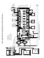
PC700 and PC705 Controls Connected to 2 EXP Switching Relays
OUTDOOR
SENSOR
SWITCH SETTINGS
Master/Slave: Master
Reset/Normal: Reset
Priority Zone: On or Off
T
SLAVE
PC700
MASTER
PLUG-IN CARDS
1 2 3 4
MASTER
ZONE
CONTROL
BOIL OUT
SEN SEN
THERMOSTATS
EXPANSION
POWER
CONTROL
INTERFACE
ZONE 1 ZONE 2 ZONE 3 ZONE 4
ZONE 4
PRIORITY
ON
OFF
SR 504-EXP
BOILER SENSOR
FOUR ZONE SWITCHING RELAY
WITH OPTIONAL PRIORITY
RESET NORMAL
POWER
ZONE 1
ZONE 2
ZONE 3
ZONE 4
24 VAC
POWER
120V RELAY
X
X
END
SWITCH
ZONE1 ZONE2
ZC ZR
ZONE3
ZONE4 POWER
120 VOLT CIRCULATORS
INPUT
FUSE 1 AMP
120 V AC INPUT
JUMPER
TO: "TT" ON BOILER
BOILER
SWITCH SETTINGS
Master/Slave: Slave
Reset/Normal: Normal
Priority Zone: No Priority
OUTDOOR
SENSOR
THERMOSTATS
GREEN/GROUND
T
(SEE NOTE B
ON PAGE 23)
SLAVE
RED
BLUE
SYSTEM
CIRCULATOR
PC705-2
BOIL SUP OUT
SEN SEN SEN
ZONE
CONTROL
BLACK
SLAVE
PLUG-IN CARDS
MASTER
1 2 3 4
EXPANSION
ZONE 1 ZONE 2 ZONE 3 ZONE 4
ZONE 4
PRIORITY
ON
OFF
SR 504-EXP
INJECTION
CIRCULATOR
RESET NORMAL
FOUR ZONE SWITCHING RELAY
WITH OPTIONAL PRIORITY
POWER
ZONE 1
ZONE 2
ZONE 3
ZONE 4
SUPPLY SENSOR
BOILER SENSOR
24 VAC
POWER
120V RELAY
X
X
END
SWITCH
ZC ZR
ZONE1 ZONE2
ZONE3
ZONE4 POWER
120 VOLT CIRCULATORS
INPUT
FUSE 1 AMP
JUMPER
SYSTEM CIRCULATOR
(OPTIONAL LOCATION)
(SEE NOTE A ON PAGE 23)
H
N
120 VAC INPUT
27
PC702 and PC705 Controls Connected to 2 EXP Switching Relays
SWITCH SETTINGS
Master/Slave: Master
Reset/Normal: Normal
Priority Zone: On or Off
OUTDOOR
SENSOR
THERMOSTATS
T
MASTER
DHW
DEMAND
SLAVE
PC702
PLUG-IN CARDS
1 2 3 4
MASTER
EXPANSION
POWER
CONTROL
INTERFACE
STAGE STAGE BOIL OUT ZONE
1
2 SEN SEN CONTROL
ZONE 1 ZONE 2 ZONE 3 ZONE 4
ZONE 4
PRIORITY
ON
OFF
SR 504-EXP
FOUR ZONE SWITCHING RELAY
WITH OPTIONAL PRIORITY
RESET NORMAL
BOILER SENSOR
POWER
ZONE 1
ZONE 2
ZONE 3
ZONE 4
24 VAC
POWER
120V RELAY
X
X
ZONE1 ZONE2
ZC ZR
END
SWITCH
ZONE3
ZONE4 POWER
120 VOLT CIRCULATORS
INPUT
BOILER
#1
FUSE 1 AMP
120 VAC INPUT
JUMPER
BOILER
#2
WIRING NEEDED ONLY IF
PRIORITY ZONE IS DHW
SWITCH SETTINGS
Master/Slave: Slave
Reset/Normal: Normal
Priority Zone: No Priority
OUTDOOR
SENSOR
THERMOSTATS
T
GREEN/GROUND
(SEE NOTE B
ON PAGE 23)
SLAVE
SLAVE
PLUG-IN CARDS
RED
BLUE
SYSTEM
CIRCULATOR
MASTER
1 2 3 4
EXPANSION
ZONE 1 ZONE 2 ZONE 3 ZONE 4
PC705-2
BOIL SUP OUT
SEN SEN SEN
ZONE
CONTROL
BLACK
ZONE 4
PRIORITY
ON
OFF
SR 504-EXP
INJECTION
CIRCULATOR
RESET NORMAL
FOUR ZONE SWITCHING RELAY
WITH OPTIONAL PRIORITY
POWER
ZONE 1
ZONE 2
ZONE 3
ZONE 4
SUPPLY SENSOR
BOILER SENSOR
24 VAC
POWER
120V RELAY
X
X
ZC ZR
END
SWITCH
ZONE1 ZONE2
ZONE3
ZONE4 POWER
120 VOLT CIRCULATORS
INPUT
FUSE 1 AMP
JUMPER
SYSTEM CIRCULATOR
(OPTIONAL LOCATION)
(SEE NOTE A ON PAGE 23)
H
N
120 VAC INPUT
28
BOILER
H
N
24 VAC
24 VAC
FACTORY
INSTALLED
TRANSFORMER
FACTORY
INSTALLED
TRANSFORMER
END
SWITCH
SYSTEM PUMP AND BOILER TURN ON
WHEN ANY ZONE VALVE OPENS.
SYSTEM
PUMP
TO BOILER AQUASTAT RELAY
120 VAC
INPUT
BLACK
WHITE
120 VAC
INPUT
BLACK
WHITE
N/O COM N/C
POWER IN
T T
ZONE 2
T T
ZONE 4
ZVC 405
T T
ZONE 3
T T
ZONE 5
T
THERMOSTAT
2 WIRE ZONE VALVE
(NO END SWITCH)
1
2
3
ZONE 3
1 2 3 4
TACO
3 WIRE ZONE VALVE
ZONE 2
1 2 3 4
MOTOR
END
SWITCH
ZONE 5
1 2 3 4
4 WIRE ZONE VALVE
(POWER OPEN, SELF CLOSING)
ZONE 4
1 2 3 4
FIVE ZONE ZONE VALVE CONTROL
JUMPER
3&4
ZONE 1
1 2 3 4
T T
ZONE 1
T
T
24 VAC
THERMOSTAT
THERMOSTAT
ZVC403/405 with System Pump
FUSE (5 AMP MAX)
29
VALVE 4
T STAT 5
VALVE 5
POWER
VALVE 2
T STAT 3
VALVE 3
T STAT 4
VALVE 1
T STAT 2
T STAT 1
BOILER
H
N
WHITE
24 VAC
24 VAC
SYSTEM PUMP AND BOILER TURN ON
WHEN ANY ZONE VALVE OPENS.
SYSTEM
PUMP
TO BOILER AQUASTAT RELAY
120 VAC
INPUT
BLACK
WHITE
120 VAC
INPUT
BLACK
FACTORY
INSTALLED
TRANSFORMER
FACTORY
INSTALLED
TRANSFORMER
EXTRA
MAIN
END
END
SWITCH SWITCH
DRY
CONTACTS
JUMPER
3&4
ZONE 1
1 2 3 4
T T
ZONE 1
2 WIRE ZONE VALVE
(NO END SWITCH)
N/O COM N/C
ZONE 6 RELAY
MODE
NORMAL RESET
ZVC 406
T T
ZONE 4
T T
ZONE 5
T
THERMOSTAT
1
2
3
ZONE 3
1 2 3 4
TACO
3 WIRE ZONE VALVE
ZONE 2
1 2 3 4
MOTOR
END
SWITCH
ZONE 5
1 2 3 4
PRIORITY
ZONE
JUMPER
3&4
ZONE 6
1 2 3 4
OFF
VALVE 4
T STAT 5
VALVE 5
T STAT 6
VALVE 6
POWER
VALVE 2
T STAT 3
VALVE 3
T STAT 4
T STAT 2
VALVE 1
T STAT 1
Note: When a circulator is used on the
priority zone instead of a zone valve,
jumper 3 and 4 of the priority zone.
ON
SEE NOTE
AQUASTAT ON
DHW HEATER
ZONE 6 PRIORITY
T T
ZONE 6
A
4 WIRE
ZONE VALVE
(POWER OPEN, SELF CLOSING)
ZONE 4
1 2 3 4
SIX ZONE ZONE VALVE CONTROL
WITH OPTIONAL PRIORITY
T T
ZONE 2
T T
ZONE 3
T
T
24 VAC
THERMOSTAT
THERMOSTAT
ZVC404/406 with System Pump
POWER IN
30
FUSE (7 AMP MAX)
BOILER
H
N
WHITE
24 VAC
24 VAC
FACTORY
INSTALLED
TRANSFORMER
FACTORY
INSTALLED
TRANSFORMER
DHW
PUMP
EXTRA
MAIN
END
END
SWITCH SWITCH
JUMPER
3&4
ZONE 1
1 2 3 4
T T
ZONE 1
T T
ZONE 4
ZVC 406
T T
ZONE 3
T T
ZONE 5
T
THERMOSTAT
1
2
3
ZONE 3
1 2 3 4
TACO
3 WIRE ZONE VALVE
ZONE 2
1 2 3 4
MOTOR
END
SWITCH
ZONE 5
1 2 3 4
AQUASTAT ON
DHW HEATER
PRIORITY
ZONE
JUMPER
3&4
ZONE 6
1 2 3 4
SEE NOTE
VALVE 4
T STAT 5
VALVE 5
T STAT 6
VALVE 6
POWER
VALVE 2
T STAT 3
VALVE 3
T STAT 4
VALVE 1
T STAT 2
T STAT 1
Note: When a circulator is used on the
priority zone instead of a zone valve,
jumper 3 and 4 of the priority zone.
ON
OFF
ZONE 6 PRIORITY
T T
ZONE 6
A
4 WIRE ZONE VALVE
(POWER OPEN, SELF CLOSING)
ZONE 4
1 2 3 4
SIX ZONE ZONE VALVE CONTROL
WITH OPTIONAL PRIORITY
T T
ZONE 2
2 WIRE ZONE VALVE
(NO END SWITCH)
N/O COM N/C
ZONE 6 RELAY
MODE
T
T
24 VAC
THERMOSTAT
THERMOSTAT
NORMAL RESET
DHW PUMP TURNS ON ONLY WHEN PRIORITY ZONE CALLS.
BOILER TURNS ON WHEN ANY ZONE VALVE OPENS.
TO BOILER AQUASTAT RELAY
120 VAC
INPUT
BLACK
WHITE
120 VAC
INPUT
BLACK
POWER IN
ZVC404/406 with Domestic Hot Water (DHW) Pump
FUSE (7 AMP MAX)
31
BOILER
H
N
WHITE
24 VAC
24 VAC
EXTRA
MAIN
END
END
SWITCH SWITCH
DHW
PUMP
DHW PUMP TURNS ON ONLY WHEN PRIORITY ZONE CALLS.
JUMPER
3&4
ZONE 1
1 2 3 4
T T
ZONE 1
T T
ZONE 4
ZVC 406
T T
ZONE 3
T T
ZONE 5
T
THERMOSTAT
1
2
3
ZONE 3
1 2 3 4
TACO
3 WIRE ZONE VALVE
ZONE 2
1 2 3 4
MOTOR
END
SWITCH
ZONE 5
1 2 3 4
AQUASTAT ON
DHW HEATER
PRIORITY
ZONE
JUMPER
3&4
ZONE 6
1 2 3 4
SEE NOTE
VALVE 4
T STAT 5
VALVE 5
T STAT 6
VALVE 6
POWER
VALVE 2
T STAT 3
VALVE 3
T STAT 4
VALVE 1
T STAT 2
T STAT 1
Note: When a circulator is used on the
priority zone instead of a zone valve,
jumper 3 and 4 of the priority zone.
ON
OFF
ZONE 6 PRIORITY
T T
ZONE 6
A
4 WIRE ZONE VALVE
(POWER OPEN, SELF CLOSING)
ZONE 4
1 2 3 4
SIX ZONE ZONE VALVE CONTROL
WITH OPTIONAL PRIORITY
T T
ZONE 2
2 WIRE ZONE VALVE
(NO END SWITCH)
N/O COM N/C
ZONE 6 RELAY
MODE
NORMAL RESET
T
T
24 VAC
THERMOSTAT
THERMOSTAT
SYSTEM PUMP AND BOILER TURN ON WHEN ANY ZONE VALVE OPENS.
SYSTEM
PUMP
TO BOILER AQUASTAT RELAY
120 VAC
INPUT
BLACK
WHITE
120 VAC
INPUT
BLACK
FACTORY
INSTALLED
TRANSFORMER
FACTORY
INSTALLED
TRANSFORMER
ZVC404/406 with System and DHW Pumps
POWER IN
32
FUSE (7 AMP MAX)
BOILER
H
N
WHITE
24 VAC
24 VAC
FACTORY
INSTALLED
TRANSFORMER
FACTORY
INSTALLED
TRANSFORMER
DHW
PUMP
EXTRA
MAIN
END
END
SWITCH SWITCH
SECONDARY PUMP COMES ON WHEN ANY ZONE CALLS EXCEPT PRIORITY ZONE.
DHW PUMP TURNS ON ONLY WHEN PRIORITY ZONE CALLS.
T T
ZONE 4
ZVC 406
T T
ZONE 3
T T
ZONE 5
T
THERMOSTAT
1
2
3
ZONE 3
1 2 3 4
TACO
3 WIRE ZONE VALVE
ZONE 2
1 2 3 4
MOTOR
END
SWITCH
ZONE 5
1 2 3 4
AQUASTAT ON
DHW HEATER
PRIORITY
ZONE
JUMPER
3&4
ZONE 6
1 2 3 4
SEE NOTE
VALVE 4
T STAT 5
VALVE 5
T STAT 6
VALVE 6
POWER
VALVE 2
T STAT 3
VALVE 3
T STAT 4
VALVE 1
T STAT 2
T STAT 1
Note: When a circulator is used on the
priority zone instead of a zone valve,
jumper 3 and 4 of the priority zone.
ON
OFF
ZONE 6 PRIORITY
T T
ZONE 6
A
4 WIRE ZONE VALVE
(POWER OPEN, SELF CLOSING)
ZONE 4
1 2 3 4
SIX ZONE ZONE VALVE CONTROL
WITH OPTIONAL PRIORITY
T T
ZONE 2
2 WIRE ZONE VALVE
(NO END SWITCH)
JUMPER
3&4
ZONE 1
1 2 3 4
T T
ZONE 1
SECONDARY
PUMP
N/O COM N/C
ZONE 6 RELAY
MODE
NORMAL RESET
T
T
24 VAC
THERMOSTAT
THERMOSTAT
SYSTEM PUMP AND BOILER TURN ON WHEN ANY ZONE VALVE OPENS.
SYSTEM
PUMP
TO BOILER AQUASTAT RELAY
120 VAC
INPUT
BLACK
WHITE
120 VAC
INPUT
BLACK
POWER IN
ZVC404/406 with System, DHW and Secondary Pumps
FUSE (7 AMP MAX)
33
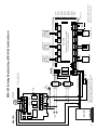
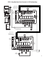
2 ZVC404/406 Connected Together with Priority
THERMOSTAT
THERMOSTAT
THERMOSTAT
T
T
T
Note: When a circulator is used on the
priority zone instead of a zone valve,
jumper 3 and 4 of the priority zone.
N
H
FACTORY
INSTALLED
TRANSFORMER
24 VAC
WHITE
120 VAC
INPUT
BLACK
ZONE 4 PRIORITY
MODE
NORMAL RESET
24
VAC
OFF
PRIORITY
ON
ON
T T
ZONE 1
POWER IN
T T
ZONE 2
FUSE (3 AMP MAX)
EXTRA
MAIN
END
END
SWITCH SWITCH
T T
ZONE 3
T T
ZONE 4
T STAT 1
VALVE 1
T STAT 2
VALVE 2
T STAT 3
ZVC 404
FOUR ZONE ZONE VALVE CONTROL
WITH OPTIONAL PRIORITY
ZONE 1
1 2 3 4
N/O COM N/C
ZONE 4 RELAY
ZONE 2
1 2 3 4
ZONE 3
1 2 3 4
VALVE 3
T STAT 4
VALVE 4
POWER
ZONE 4
1 2 3 4
TO BOILER
AQUASTAT RELAY
JUMPER
3&4
JUMPER
3&4
SEE NOTE
PRIORITY
ZONE
1
2
3
DRY
CONTACTS
MOTOR
TACO
3 WIRE ZONE VALVE
2 WIRE ZONE VALVE
(NO END SWITCH)
END
SWITCH
4 WIRE ZONE VALVE
(POWER OPEN,
SELF CLOSING)
THERMOSTAT
THERMOSTAT
THERMOSTAT
T
T
T
AQUASTAT ON
DHW HEATER
A
WHITE
120 VAC
INPUT
BLACK
FACTORY
INSTALLED
TRANSFORMER
24 VAC
ZONE 4 PRIORITY
MODE
NORMAL RESET
24
VAC
OFF
ON
T T
ZONE 1
POWER IN
FUSE (3 AMP MAX)
EXTRA
MAIN
END
END
SWITCH SWITCH
N/O COM N/C
ZONE 4 RELAY
T T
ZONE 2
T T
ZONE 3
ZONE 1
1 2 3 4
ZONE 2
1 2 3 4
ZONE 3
1 2 3 4
VALVE 3
T STAT 4
VALVE 4
POWER
ZONE 4
1 2 3 4
JUMPER
3&4
PRIORITY
ZONE
1
2
3
DRY
CONTACTS
2 WIRE ZONE VALVE
(NO END SWITCH)
TACO
3 WIRE ZONE VALVE
MOTOR
END
SWITCH
4 WIRE ZONE VALVE
(POWER OPEN,
SELF CLOSING)
T STAT 1
VALVE 1
T STAT 2
VALVE 2
T STAT 3
ZVC 404
TO BOILER AQUASTAT RELAY
34
T T
ZONE 4
FOUR ZONE ZONE VALVE CONTROL
WITH OPTIONAL PRIORITY
JUMPER
3&4
BOILER
PRIORITY
ON
SEE NOTE
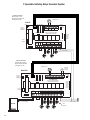
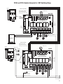
2 EXP Zone Valve Controls Connected Together with System Pump
Note: When a circulator is used on the
priority zone instead of a zone valve,
jumper 3 and 4 of the priority zone.
SWITCH SETTINGS
Master/Slave: Master
Reset/Normal: Normal
Priority Zone: On
T
T
24 VAC
SLAVE
POWER
CONTROLS
24 VAC
TACO, INC ZVC406-EXP
FACTORY
INSTALLED
TRANSFORMER
120 VAC
INPUT
BLACK
RESET
1 2 3 4
T T
ZONE 1
EXPANSION
MASTER
NORMAL
T T
ZONE 2
T T
ZONE 3
T T
ZONE 4
T T
ZONE 5
T T
ZONE 6
OFF
T STAT 1
VALVE 1
T STAT 2
ZVC 406-EXP
VALVE 2
SIX ZONE ZONE VALVE CONTROL
WITH OPTIONAL PRIORITY
FUSE 7 AMP MAX
24 VAC
MODE
WHITE
ZONE 6
PRIORITY
ON
PLUG-IN
CARDS
POWER IN
WHITE
FACTORY
INSTALLED
TRANSFORMER
MASTER
120 VAC
INPUT
BLACK
AQUASTAT ON
DHW HEATER
A
T
T STAT 3
VALVE 3
T STAT 4
VALVE 4
T STAT 5
VALVE 5
T STAT 6
END
SWITCH
B
PUMP
N/O COM N/C
ZONE 6 RELAY
ZONE 1
1 2 3 4
END
SWITCH
A
BOILER
ZONE 2
1 2 3 4
ZONE 3
1 2 3 4
ZONE 4
1 2 3 4
ZONE 5
1 2 3 4
ZONE 6
1 2 3 4
VALVE 6
POWER ON
JUMPER
3&4
JUMPER
3&4
SEE NOTE
PRIORITY
ZONE
TO BOILER AQUASTAT RELAY
MOTOR
1
2
3
BOILER
TACO
3 WIRE ZONE VALVE
2 WIRE ZONE VALVE
(NO END SWITCH)
SYSTEM
PUMP
END
SWITCH
4 WIRE ZONE VALVE
(POWER OPEN, SELF CLOSING)
N
H
120 VAC
INPUT
SYSTEM PUMP AND BOILER TURN ON WHEN ANY ZONE VALVE OPENS.
SWITCH SETTINGS
Master/Slave: Slave
Reset/Normal: Normal
Priority Zone: Off
T
T
T
SLAVE
POWER
CONTROLS
24 VAC
TACO, INC ZVC406-EXP
FACTORY
INSTALLED
TRANSFORMER
120 VAC
INPUT
BLACK
RESET
1 2 3 4
T T
ZONE 1
EXPANSION
MASTER
NORMAL
T T
ZONE 2
T T
ZONE 3
T T
ZONE 4
T T
ZONE 5
T T
ZONE 6
OFF
T STAT 1
VALVE 1
T STAT 2
ZVC 406-EXP
VALVE 2
SIX ZONE ZONE VALVE CONTROL
WITH OPTIONAL PRIORITY
FUSE 7 AMP MAX
24 VAC
MODE
WHITE
ZONE 6
PRIORITY
ON
PLUG-IN
CARDS
POWER IN
WHITE
120 VAC
INPUT
BLACK
FACTORY
INSTALLED
TRANSFORMER
SLAVE
T STAT 3
VALVE 3
T STAT 4
VALVE 4
T STAT 5
VALVE 5
T STAT 6
END
SWITCH
B
PUMP
N/O COM N/C
ZONE 6 RELAY
DRY
CONTACTS
END
SWITCH
A
BOILER
ZONE 1
1 2 3 4
ZONE 2
1 2 3 4
ZONE 3
1 2 3 4
ZONE 4
1 2 3 4
ZONE 5
1 2 3 4
ZONE 6
1 2 3 4
JUMPER
3&4
JUMPER
3&4
1
2
3
2 WIRE
ZONE VALVE
(NO END SWITCH)
TACO
3 WIRE
ZONE VALVE
MOTOR
END
SWITCH
VALVE 6
POWER ON
SEE NOTE
PRIORITY
ZONE
4 WIRE
ZONE VALVE
(POWER OPEN, SELF CLOSING)
35
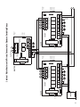
2 EXP Zone Valve Controls Connected Together with DHW Pump
Note: When a circulator is used on the
priority zone instead of a zone valve,
jumper 3 and 4 of the priority zone.
SWITCH SETTINGS
Master/Slave: Master
Reset/Normal: Normal
Priority Zone: On
T
T
24 VAC
SLAVE
POWER
CONTROLS
24 VAC
TACO, INC ZVC406-EXP
FACTORY
INSTALLED
TRANSFORMER
120 VAC
INPUT
BLACK
RESET
1 2 3 4
T T
ZONE 1
EXPANSION
MASTER
NORMAL
T T
ZONE 2
T T
ZONE 3
T T
ZONE 4
T T
ZONE 5
T T
ZONE 6
OFF
T STAT 1
VALVE 1
T STAT 2
ZVC 406-EXP
VALVE 2
SIX ZONE ZONE VALVE CONTROL
WITH OPTIONAL PRIORITY
FUSE 7 AMP MAX
24 VAC
MODE
WHITE
ZONE 6
PRIORITY
ON
PLUG-IN
CARDS
POWER IN
WHITE
FACTORY
INSTALLED
TRANSFORMER
MASTER
120 VAC
INPUT
BLACK
AQUASTAT ON
DHW HEATER
A
T
T STAT 3
VALVE 3
T STAT 4
VALVE 4
T STAT 5
VALVE 5
T STAT 6
END
SWITCH
B
PUMP
N/O COM N/C
ZONE 6 RELAY
ZONE 1
1 2 3 4
END
SWITCH
A
BOILER
TO BOILER
AQUASTAT RELAY
ZONE 2
1 2 3 4
ZONE 3
1 2 3 4
ZONE 4
1 2 3 4
ZONE 5
1 2 3 4
ZONE 6
1 2 3 4
VALVE 6
POWER ON
JUMPER
3&4
JUMPER
3&4
SEE NOTE
PRIORITY
ZONE
MOTOR
1
2
3
BOILER
TACO
3 WIRE ZONE VALVE
2 WIRE ZONE VALVE
(NO END SWITCH)
DHW
PUMP
END
SWITCH
4 WIRE ZONE VALVE
(POWER OPEN, SELF CLOSING)
N
H
120 VAC
INPUT
BOILER TURNS ON WHEN ANY ZONE VALVE OPENS.
DHW PUMP TURNS ON ONLY WHEN PRIORITY ZONE CALLS.
SWITCH SETTINGS
Master/Slave: Slave
Reset/Normal: Normal
Priority Zone: Off
T
T
T
SLAVE
POWER
CONTROLS
24 VAC
TACO, INC ZVC406-EXP
FACTORY
INSTALLED
TRANSFORMER
120 VAC
INPUT
BLACK
RESET
1 2 3 4
T T
ZONE 1
EXPANSION
MASTER
NORMAL
T T
ZONE 2
T T
ZONE 3
T T
ZONE 5
T T
ZONE 6
OFF
T STAT 1
VALVE 1
T STAT 2
VALVE 2
SIX ZONE ZONE VALVE CONTROL
WITH OPTIONAL PRIORITY
T STAT 3
VALVE 3
T STAT 4
VALVE 4
T STAT 5
VALVE 5
T STAT 6
END
SWITCH
B
PUMP
N/O COM N/C
ZONE 6 RELAY
DRY
CONTACTS
END
SWITCH
A
BOILER
ZONE 1
1 2 3 4
ZONE 2
1 2 3 4
ZONE 3
1 2 3 4
ZONE 4
1 2 3 4
ZONE 5
1 2 3 4
ZONE 6
1 2 3 4
JUMPER
3&4
JUMPER
3&4
1
2
3
2 WIRE
ZONE VALVE
(NO END SWITCH)
36
T T
ZONE 4
ZVC 406-EXP
FUSE 7 AMP MAX
24 VAC
MODE
WHITE
ZONE 6
PRIORITY
ON
PLUG-IN
CARDS
POWER IN
WHITE
120 VAC
INPUT
BLACK
FACTORY
INSTALLED
TRANSFORMER
SLAVE
TACO
3 WIRE
ZONE VALVE
MOTOR
END
SWITCH
PRIORITY
ZONE
4 WIRE
ZONE VALVE
(POWER OPEN, SELF CLOSING)
VALVE 6
POWER ON
SEE NOTE
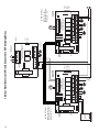
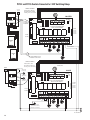
2 EXP Zone Valve Controls Connected Together with System and DHW Pumps
Note: When a circulator is used on the
priority zone instead of a zone valve,
jumper 3 and 4 of the priority zone.
SWITCH SETTINGS
Master/Slave: Master
Reset/Normal: Normal
Priority Zone: On
T
T
24 VAC
SLAVE
1 2 3 4
POWER
CONTROLS
24 VAC
TACO, INC ZVC406-EXP
FACTORY
INSTALLED
TRANSFORMER
120 VAC
INPUT
BLACK
RESET
T T
ZONE 1
EXPANSION
MASTER
NORMAL
T T
ZONE 2
T T
ZONE 3
T T
ZONE 4
T T
ZONE 5
T T
ZONE 6
OFF
T STAT 1
VALVE 1
T STAT 2
ZVC 406-EXP
VALVE 2
SIX ZONE ZONE VALVE CONTROL
WITH OPTIONAL PRIORITY
FUSE 7 AMP MAX
24 VAC
MODE
WHITE
ZONE 6
PRIORITY
ON
PLUG-IN
CARDS
POWER IN
WHITE
FACTORY
INSTALLED
TRANSFORMER
MASTER
120 VAC
INPUT
BLACK
AQUASTAT ON
DHW HEATER
A
T
T STAT 3
VALVE 3
T STAT 4
VALVE 4
T STAT 5
VALVE 5
T STAT 6
END
SWITCH
B
PUMP
N/O COM N/C
ZONE 6 RELAY
ZONE 1
1 2 3 4
END
SWITCH
A
BOILER
TO BOILER
AQUASTAT RELAY
ZONE 2
1 2 3 4
ZONE 3
1 2 3 4
ZONE 4
1 2 3 4
ZONE 5
1 2 3 4
ZONE 6
1 2 3 4
VALVE 6
POWER ON
JUMPER
3&4
JUMPER
3&4
SEE NOTE
PRIORITY
ZONE
BOILER
MOTOR
1
2
3
SYSTEM
PUMP
DHW
PUMP
TACO
3 WIRE ZONE VALVE
2 WIRE ZONE VALVE
(NO END SWITCH)
END
SWITCH
4 WIRE ZONE VALVE
(POWER OPEN, SELF CLOSING)
N
H
120 VAC
INPUT
SYSTEM PUMP AND BOILER TURN ON WHEN ANY ZONE VALVE OPENS.
DHW PUMP TURNS ON ONLY WHEN PRIORITY ZONE CALLS.
SWITCH SETTINGS
Master/Slave: Slave
Reset/Normal: Normal
Priority Zone: Off
T
T
T
SLAVE
POWER
CONTROLS
24 VAC
TACO, INC ZVC406-EXP
FACTORY
INSTALLED
TRANSFORMER
120 VAC
INPUT
BLACK
RESET
1 2 3 4
T T
ZONE 1
EXPANSION
MASTER
NORMAL
T T
ZONE 2
T T
ZONE 3
T T
ZONE 4
T T
ZONE 5
T T
ZONE 6
OFF
T STAT 1
VALVE 1
T STAT 2
ZVC 406-EXP
VALVE 2
SIX ZONE ZONE VALVE CONTROL
WITH OPTIONAL PRIORITY
FUSE 7 AMP MAX
24 VAC
MODE
WHITE
ZONE 6
PRIORITY
ON
PLUG-IN
CARDS
POWER IN
WHITE
120 VAC
INPUT
BLACK
FACTORY
INSTALLED
TRANSFORMER
SLAVE
T STAT 3
VALVE 3
T STAT 4
VALVE 4
T STAT 5
VALVE 5
T STAT 6
END
SWITCH
B
PUMP
N/O COM N/C
ZONE 6 RELAY
DRY
CONTACTS
END
SWITCH
A
BOILER
ZONE 1
1 2 3 4
ZONE 2
1 2 3 4
ZONE 3
1 2 3 4
ZONE 4
1 2 3 4
ZONE 5
1 2 3 4
ZONE 6
1 2 3 4
JUMPER
3&4
JUMPER
3&4
1
2
3
2 WIRE
ZONE VALVE
(NO END SWITCH)
TACO
3 WIRE
ZONE VALVE
MOTOR
END
SWITCH
VALVE 6
POWER ON
SEE NOTE
PRIORITY
ZONE
4 WIRE
ZONE VALVE
(POWER OPEN, SELF CLOSING)
37
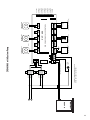
2 EXP Zone Valve Controls Connected Together with System, DHW and Secondary Pumps
Note: When a circulator is used on the
priority zone instead of a zone valve,
jumper 3 and 4 of the priority zone.
SWITCH SETTINGS
Master/Slave: Master
Reset/Normal: Normal
Priority Zone: On
T
T
24 VAC
SLAVE
POWER
CONTROLS
TACO, INC ZVC406-EXP
FACTORY
INSTALLED
TRANSFORMER
120 VAC
INPUT
BLACK
24 VAC
RESET
1 2 3 4
T T
ZONE 1
EXPANSION
MASTER
NORMAL
T T
ZONE 2
T T
ZONE 3
T T
ZONE 4
T T
ZONE 5
T T
ZONE 6
OFF
T STAT 1
VALVE 1
T STAT 2
ZVC 406-EXP
VALVE 2
SIX ZONE ZONE VALVE CONTROL
WITH OPTIONAL PRIORITY
FUSE 7 AMP MAX
24 VAC
MODE
WHITE
ZONE 6
PRIORITY
ON
PLUG-IN
CARDS
POWER IN
WHITE
FACTORY
INSTALLED
TRANSFORMER
MASTER
120 VAC
INPUT
BLACK
AQUASTAT ON
DHW HEATER
A
T
T STAT 3
VALVE 3
T STAT 4
VALVE 4
T STAT 5
VALVE 5
T STAT 6
END
SWITCH
B
PUMP
N/O COM N/C
ZONE 6 RELAY
ZONE 1
1 2 3 4
END
SWITCH
A
BOILER
TO BOILER
AQUASTAT RELAY
ZONE 2
1 2 3 4
ZONE 3
1 2 3 4
ZONE 4
1 2 3 4
ZONE 5
1 2 3 4
ZONE 6
1 2 3 4
VALVE 6
POWER ON
JUMPER
3&4
JUMPER
3&4
SEE NOTE
PRIORITY
ZONE
BOILER
DHW
PUMP
MOTOR
1
2
3
SYSTEM
PUMP
SECONDARY
PUMP
TACO
3 WIRE ZONE VALVE
2 WIRE ZONE VALVE
(NO END SWITCH)
END
SWITCH
4 WIRE ZONE VALVE
(POWER OPEN, SELF CLOSING)
N
H
120 VAC
INPUT
SYSTEM PUMP AND BOILER TURN ON WHEN ANY ZONE VALVE OPENS.
DHW PUMP TURNS ON ONLY WHEN PRIORITY ZONE CALLS.
SECONDARY PUMP TURNS ON WHEN ANY ZONE CALLS, EXCEPT PRIORITY ZONE.
SWITCH SETTINGS
Master/Slave: Slave
Reset/Normal: Normal
Priority Zone: Off
T
T
T
SLAVE
POWER
CONTROLS
24 VAC
TACO, INC ZVC406-EXP
FACTORY
INSTALLED
TRANSFORMER
120 VAC
INPUT
BLACK
RESET
1 2 3 4
T T
ZONE 1
EXPANSION
MASTER
NORMAL
T T
ZONE 2
T T
ZONE 3
T T
ZONE 5
T T
ZONE 6
OFF
T STAT 1
VALVE 1
T STAT 2
VALVE 2
SIX ZONE ZONE VALVE CONTROL
WITH OPTIONAL PRIORITY
T STAT 3
VALVE 3
T STAT 4
VALVE 4
T STAT 5
VALVE 5
T STAT 6
END
SWITCH
B
PUMP
N/O COM N/C
ZONE 6 RELAY
DRY
CONTACTS
END
SWITCH
A
BOILER
ZONE 1
1 2 3 4
ZONE 2
1 2 3 4
ZONE 3
1 2 3 4
ZONE 4
1 2 3 4
ZONE 5
1 2 3 4
ZONE 6
1 2 3 4
JUMPER
3&4
JUMPER
3&4
1
2
3
2 WIRE
ZONE VALVE
(NO END SWITCH)
38
T T
ZONE 4
ZVC 406-EXP
FUSE 7 AMP MAX
24 VAC
MODE
WHITE
ZONE 6
PRIORITY
ON
PLUG-IN
CARDS
POWER IN
WHITE
120 VAC
INPUT
BLACK
FACTORY
INSTALLED
TRANSFORMER
SLAVE
TACO
3 WIRE
ZONE VALVE
MOTOR
END
SWITCH
PRIORITY
ZONE
4 WIRE
ZONE VALVE
(POWER OPEN, SELF CLOSING)
VALVE 6
POWER ON
SEE NOTE
39
BOILER
OUTDOOR
SENSOR
ZONE
CONTROL
TACO, INC ZVC406-EXP
END
SWITCH
B
PUMP
RESET
NORMAL
END
SWITCH
A
BOILER
SYSTEM
CIRCULATOR
DRY
CONTACTS
1 2 3 4
JUMPER
3&4
ZONE 1
1 2 3 4
T T
ZONE 4
ZVC 406-EXP
T T
ZONE 3
T T
ZONE 5
T
THERMOSTAT
TACO
3 WIRE ZONE VALVE
1
2
3
ZONE 3
1 2 3 4
MOTOR
END
SWITCH
ZONE 5
1 2 3 4
OFF
PRIORITY
ZONE
JUMPER
3&4
ZONE 6
1 2 3 4
T T
ZONE 6
ZONE 6
PRIORITY
ON
4 WIRE ZONE VALVE
(POWER OPEN, SELF CLOSING)
ZONE 4
1 2 3 4
SIX ZONE ZONE VALVE CONTROL
WITH OPTIONAL PRIORITY
T T
ZONE 2
ZONE 2
1 2 3 4
T T
ZONE 1
2 WIRE ZONE VALVE
(NO END SWITCH)
EXPANSION
MASTER
N/O COM N/C
ZONE 6 RELAY
MODE
SLAVE
POWER
CONTROLS
PLUG-IN
CARDS
T
T
24 VAC
THERMOSTAT
THERMOSTAT
SYSTEM CIRCULATOR AND BOILER TURN ON WHEN ANY ZONE VALVE OPENS.
24 VAC
TO BOILER
AQUASTAT RELAY
120 VAC
INPUT
BLACK
WHITE
120 VAC
INPUT
BLACK
24 VAC
BOILER SENSOR
WHITE
BOIL OUT
SEN SEN
Note: When a circulator is used on the
priority zone instead of a zone valve,
jumper 3 and 4 of the priority zone.
SWITCH SETTINGS
Master/Slave: Master
Reset/Normal: Reset
Priority Zone: On or Off
POWER IN
PC700
FACTORY
INSTALLED
TRANSFORMER
FACTORY
INSTALLED
TRANSFORMER
PC700 Boiler Reset Control Connected To EXP Zone Valve Control
FUSE 7 AMP MAX
N
H
SEE NOTE
POWER ON
VALVE 6
T STAT 6
VALVE 5
T STAT 5
VALVE 4
T STAT 4
VALVE 3
T STAT 3
VALVE 2
T STAT 2
VALVE 1
T STAT 1
INDIRECT
WATER HEATER
AQUASTAT
OR THERMOSTAT
BOILER
#2
BOILER
#1
BOILER SENSOR
STAGE STAGE BOIL OUT ZONE
1
2 SEN SEN CONTROL
BLACK
120 VAC
INPUT
WHITE
BLACK
120 VAC
INPUT
WHITE
24 VAC
WIRING NEEDED ONLY IF
PRIORITY ZONE IS DHW
N/O COM N/C
ZONE 6 RELAY
END
SWITCH
A
BOILER
DHW
CIRCULATOR
NORMAL
SYSTEM
CIRCULATOR
1 2 3 4
JUMPER
3&4
ZONE 1
1 2 3 4
T T
ZONE 4
ZVC 406-EXP
T T
ZONE 3
T T
ZONE 5
T
THERMOSTAT
TACO
3 WIRE ZONE VALVE
1
2
3
ZONE 3
1 2 3 4
MOTOR
END
SWITCH
ZONE 5
1 2 3 4
OFF
PRIORITY
ZONE
JUMPER
3&4
ZONE 6
1 2 3 4
T T
ZONE 6
ZONE 6
PRIORITY
ON
4 WIRE ZONE VALVE
(POWER OPEN, SELF CLOSING)
ZONE 4
1 2 3 4
SIX ZONE ZONE VALVE CONTROL
WITH OPTIONAL PRIORITY
T T
ZONE 2
ZONE 2
1 2 3 4
T T
ZONE 1
2 WIRE ZONE VALVE
(NO END SWITCH)
EXPANSION
MASTER
PLUG-IN
CARDS
T
T
24 VAC
THERMOSTAT
THERMOSTAT
SYSTEM CIRCULATOR AND BOILER TURN ON WHEN ANY ZONE VALVE OPENS.
DHW CIRCULATOR TURNS ON ONLY WHEN PRIORITY ZONE CALLS.
END
SWITCH
B
PUMP
RESET
MODE
SLAVE
POWER
CONTROLS
Note: When a circulator is used on the
priority zone instead of a zone valve,
jumper 3 and 4 of the priority zone.
TACO, INC ZVC406-EXP
PC702
SWITCH SETTINGS
Master/Slave: Master
Reset/Normal: Normal
Priority Zone: On or Off
24 VAC
DHW
DEMAND
FACTORY
INSTALLED
TRANSFORMER
FACTORY
INSTALLED
TRANSFORMER
POWER IN
OUTDOOR
SENSOR
PC702 2–Stage Boiler Reset Control Connected To EXP Zone Valve Control
FUSE 7 AMP MAX
40
N
H
SEE NOTE
POWER ON
VALVE 6
T STAT 6
VALVE 5
T STAT 5
VALVE 4
T STAT 4
VALVE 3
T STAT 3
VALVE 2
T STAT 2
VALVE 1
T STAT 1
INDIRECT
WATER HEATER
AQUASTAT
OR THERMOSTAT
41
BOILER
ZONE
CONTROL
WHITE
BLACK
120 VAC
INPUT
BLACK
WHITE
120 VAC
INPUT
BLACK
BOILER SENSOR
SUPPLY SENSOR
BOIL SUP OUT
SEN SEN SEN
PC705-2
BLUE
RED
TO BOILER
AQUASTAT RELAY
24 VAC
END
SWITCH
B
PUMP
N/O COM N/C
ZONE 6 RELAY
NORMAL
DRY
CONTACTS
1 2 3 4
END
SWITCH
A
BOILER
JUMPER
3&4
ZONE 1
1 2 3 4
T T
ZONE 4
ZVC 406-EXP
T T
ZONE 3
T T
ZONE 5
T
THERMOSTAT
TACO
3 WIRE ZONE VALVE
1
2
3
ZONE 3
1 2 3 4
MOTOR
END
SWITCH
ZONE 5
1 2 3 4
OFF
PRIORITY
ZONE
JUMPER
3&4
ZONE 6
1 2 3 4
T T
ZONE 6
ZONE 6
PRIORITY
ON
4 WIRE ZONE VALVE
(POWER OPEN, SELF CLOSING)
ZONE 4
1 2 3 4
SIX ZONE ZONE VALVE CONTROL
WITH OPTIONAL PRIORITY
T T
ZONE 2
ZONE 2
1 2 3 4
T T
ZONE 1
2 WIRE ZONE VALVE
(NO END SWITCH)
EXPANSION
MASTER
SYSTEM CIRCULATOR
(OPTIONAL LOCATION)
RESET
MODE
SLAVE
POWER
CONTROLS
T
T
24 VAC
THERMOSTAT
Note: When a circulator is used on the
priority zone instead of a zone valve,
jumper 3 and 4 of the priority zone.
THERMOSTAT
PLUG-IN
CARDS
SWITCH SETTINGS
Master/Slave: Master
Reset/Normal: Reset
Priority Zone: On or Off
SYSTEM CIRCULATOR AND BOILER TURN ON WHEN ANY ZONE VALVE OPENS.
24 VAC
INJECTION
CIRCULATOR
(SEE NOTE B ON PAGE 23)
SYSTEM
CIRCULATOR
TACO, INC ZVC406-EXP
GREEN/GROUND
FACTORY
INSTALLED
TRANSFORMER
FACTORY
INSTALLED
TRANSFORMER
POWER IN
OUTDOOR
SENSOR
PC705 Variable Speed Pump Injection Control Connected To EXP Zone Valve Control
FUSE 7 AMP MAX
N
H
SEE NOTE
POWER ON
VALVE 6
T STAT 6
VALVE 5
T STAT 5
VALVE 4
T STAT 4
VALVE 3
T STAT 3
VALVE 2
T STAT 2
VALVE 1
T STAT 1
INDIRECT
WATER HEATER
AQUASTAT
OR THERMOSTAT
PC700 Boiler Reset Control Connected To 2 EXP Zone Valve Controls
OUTDOOR
SENSOR
Note: When a circulator is used on the
priority zone instead of a zone valve,
jumper 3 and 4 of the priority zone.
SWITCH SETTINGS
Master/Slave: Master
Reset/Normal: Reset
Priority Zone: On or Off
INDIRECT WATER HEATER
AQUASTAT OR THERMOSTAT
PC700
ZONE
CONTROL
T
BOILER SENSOR
T
24 VAC
TACO, INC ZVC406-EXP
FACTORY
INSTALLED
TRANSFORMER
120 VAC
INPUT
BLACK
ZONE 6
PRIORITY
ON
PLUG-IN
CARDS
24 VAC
SLAVE
POWER
CONTROLS
RESET
1 2 3 4
T T
ZONE 1
EXPANSION
MASTER
MODE
WHITE
T
24 VAC
NORMAL
T T
ZONE 2
T T
ZONE 3
T T
ZONE 4
T T
ZONE 5
T T
ZONE 6
T STAT 1
OFF
VALVE 1
T STAT 2
ZVC 406-EXP
VALVE 2
SIX ZONE ZONE VALVE CONTROL
WITH OPTIONAL PRIORITY
FUSE 7 AMP MAX
WHITE
120 VAC
INPUT
BLACK
FACTORY
INSTALLED
TRANSFORMER
MASTER
POWER IN
BOIL OUT
SEN SEN
T STAT 3
VALVE 3
T STAT 4
VALVE 4
T STAT 5
VALVE 5
T STAT 6
END
SWITCH
B
PUMP
ZONE 1
1 2 3 4
END
SWITCH
A
BOILER
N/O COM N/C
ZONE 6 RELAY
TO BOILER
AQUASTAT RELAY
ZONE 2
1 2 3 4
ZONE 3
1 2 3 4
ZONE 4
1 2 3 4
ZONE 5
1 2 3 4
ZONE 6
1 2 3 4
MOTOR
1
2
3
BOILER
DHW
CIRCULATOR
POWER ON
JUMPER
3&4
JUMPER
3&4
SYSTEM
CIRCULATOR
VALVE 6
TACO
3 WIRE ZONE VALVE
2 WIRE ZONE VALVE
(NO END SWITCH)
SEE NOTE
PRIORITY
ZONE
END
SWITCH
4 WIRE ZONE VALVE
(POWER OPEN, SELF CLOSING)
H
N
SYSTEM CIRCULATOR AND BOILER TURN ON WHEN ANY ZONE VALVE OPENS.
DHW CIRCULATOR TURNS ON ONLY WHEN PRIORITY ZONE CALLS.
SWITCH SETTINGS
Master/Slave: Slave
Reset/Normal: Normal
Priority Zone: Off
T
120 VAC
INPUT
BLACK
SLAVE
POWER
CONTROLS
MODE
24 VAC
RESET
1 2 3 4
T T
ZONE 1
EXPANSION
MASTER
NORMAL
T T
ZONE 2
T T
ZONE 3
T T
ZONE 4
T T
ZONE 5
T T
ZONE 6
OFF
T STAT 1
VALVE 1
T STAT 2
ZVC 406-EXP
VALVE 2
SIX ZONE ZONE VALVE CONTROL
WITH OPTIONAL PRIORITY
T STAT 3
VALVE 3
T STAT 4
VALVE 4
T STAT 5
VALVE 5
T STAT 6
END
SWITCH
B
PUMP
N/O COM N/C
ZONE 6 RELAY
DRY
CONTACTS
END
SWITCH
A
BOILER
ZONE 1
1 2 3 4
ZONE 2
1 2 3 4
ZONE 3
1 2 3 4
ZONE 4
1 2 3 4
ZONE 5
1 2 3 4
2 WIRE ZONE VALVE
(NO END SWITCH)
ZONE 6
1 2 3 4
JUMPER
3&4
JUMPER
3&4
1
2
3
42
T
ZONE 6
PRIORITY
ON
FUSE 7 AMP MAX
WHITE
FACTORY
INSTALLED
TRANSFORMER
BLACK
POWER IN
120 VAC
INPUT
T
24 VAC
PLUG-IN
CARDS
24 VAC
TACO, INC ZVC406-EXP
WHITE
FACTORY
INSTALLED
TRANSFORMER
SLAVE
TACO
3 WIRE ZONE VALVE
MOTOR
END
SWITCH
PRIORITY
ZONE
4 WIRE ZONE VALVE
(POWER OPEN, SELF CLOSING)
VALVE 6
POWER ON
SEE NOTE
PC702 2–Stage Boiler Reset Control Connected To 2 EXP Zone Valve Controls
OUTDOOR
SENSOR
Note: When a circulator is used on the
priority zone instead of a zone valve,
jumper 3 and 4 of the priority zone.
SWITCH SETTINGS
Master/Slave: Master
Reset/Normal: Normal
Priority Zone: On or Off
DHW
DEMAND
PC702
WIRING NEEDED ONLY IF
PRIORITY ZONE IS DHW
INDIRECT WATER HEATER
AQUASTAT OR THERMOSTAT
STAGE STAGE BOIL OUT ZONE
1
2 SEN SEN CONTROL
T
BOILER SENSOR
T
SLAVE
POWER
CONTROLS
24 VAC
TACO, INC ZVC406-EXP
FACTORY
INSTALLED
TRANSFORMER
120 VAC
INPUT
BLACK
RESET
1 2 3 4
ZONE 6
PRIORITY
ON
T T
ZONE 1
EXPANSION
MASTER
NORMAL
T T
ZONE 2
T T
ZONE 3
T T
ZONE 4
T T
ZONE 5
T T
ZONE 6
OFF
T STAT 1
VALVE 1
T STAT 2
ZVC 406-EXP
VALVE 2
SIX ZONE ZONE VALVE CONTROL
WITH OPTIONAL PRIORITY
FUSE 7 AMP MAX
24 VAC
MODE
WHITE
T
24 VAC
PLUG-IN
CARDS
POWER IN
WHITE
120 VAC
INPUT
BLACK
FACTORY
INSTALLED
TRANSFORMER
MASTER
T STAT 3
VALVE 3
T STAT 4
VALVE 4
T STAT 5
VALVE 5
T STAT 6
END
SWITCH
B
PUMP
N/O COM N/C
ZONE 6 RELAY
ZONE 1
1 2 3 4
END
SWITCH
A
BOILER
ZONE 2
1 2 3 4
ZONE 3
1 2 3 4
ZONE 4
1 2 3 4
ZONE 5
1 2 3 4
ZONE 6
1 2 3 4
POWER ON
JUMPER
3&4
JUMPER
3&4
BOILER
#1
VALVE 6
SEE NOTE
PRIORITY
ZONE
MOTOR
1
2
3
SYSTEM
CIRCULATOR
DHW
CIRCULATOR
TACO
3 WIRE ZONE VALVE
2 WIRE ZONE VALVE
(NO END SWITCH)
END
SWITCH
4 WIRE ZONE VALVE
(POWER OPEN, SELF CLOSING)
H
N
SYSTEM CIRCULATOR AND BOILER TURN ON WHEN ANY ZONE VALVE OPENS.
DHW CIRCULATOR TURNS ON ONLY WHEN PRIORITY ZONE CALLS.
BOILER
#2
SWITCH SETTINGS
Master/Slave: Slave
Reset/Normal: Normal
Priority Zone: Off
T
T
SLAVE
POWER
CONTROLS
24 VAC
TACO, INC ZVC406-EXP
FACTORY
INSTALLED
TRANSFORMER
120 VAC
INPUT
BLACK
RESET
1 2 3 4
ZONE 6
PRIORITY
ON
T T
ZONE 1
EXPANSION
MASTER
NORMAL
T T
ZONE 2
T T
ZONE 3
T T
ZONE 4
T T
ZONE 5
T T
ZONE 6
OFF
T STAT 1
VALVE 1
T STAT 2
ZVC 406-EXP
VALVE 2
SIX ZONE ZONE VALVE CONTROL
WITH OPTIONAL PRIORITY
FUSE 7 AMP MAX
24 VAC
MODE
WHITE
T
24 VAC
PLUG-IN
CARDS
POWER IN
WHITE
120 VAC
INPUT
BLACK
FACTORY
INSTALLED
TRANSFORMER
SLAVE
T STAT 3
VALVE 3
T STAT 4
VALVE 4
T STAT 5
VALVE 5
T STAT 6
END
SWITCH
B
PUMP
N/O COM N/C
ZONE 6 RELAY
DRY
CONTACTS
END
SWITCH
A
BOILER
ZONE 1
1 2 3 4
ZONE 2
1 2 3 4
ZONE 3
1 2 3 4
ZONE 4
1 2 3 4
ZONE 5
1 2 3 4
ZONE 6
1 2 3 4
JUMPER
3&4
JUMPER
3&4
VALVE 6
POWER ON
SEE NOTE
PRIORITY
ZONE
1
2
3
2 WIRE ZONE VALVE
(NO END SWITCH)
TACO
3 WIRE ZONE VALVE
MOTOR
END
SWITCH
4 WIRE ZONE VALVE
(POWER OPEN, SELF CLOSING)
43
PC705 Variable Speed Pump Injection Control Connected To 2 EXP Zone Valve Controls
OUTDOOR
SENSOR
SWITCH SETTINGS
Master/Slave: Master
Reset/Normal: Reset
Priority Zone: On or Off
GREEN/GROUND
(SEE NOTE B ON PAGE 23)
RED
SYSTEM
CIRCULATOR
Note: When a circulator is used on the
priority zone instead of a zone valve,
jumper 3 and 4 of the priority zone.
BLUE
PC705-2
INJECTION
CIRCULATOR
BLACK
BOIL SUP OUT
SEN SEN SEN
INDIRECT WATER HEATER
AQUASTAT OR THERMOSTAT
ZONE
CONTROL
T
SUPPLY SENSOR
T
24 VAC
SLAVE
POWER
CONTROLS
BLACK
24 VAC
TACO, INC ZVC406-EXP
WHITE
FACTORY
INSTALLED
TRANSFORMER
MODE
RESET
1 2 3 4
T T
ZONE 1
EXPANSION
MASTER
NORMAL
T T
ZONE 2
T T
ZONE 3
T T
ZONE 4
T T
ZONE 5
T T
ZONE 6
OFF
T STAT 1
VALVE 1
T STAT 2
ZVC 406-EXP
VALVE 2
SIX ZONE ZONE VALVE CONTROL
WITH OPTIONAL PRIORITY
FUSE 7 AMP MAX
BLACK
ZONE 6
PRIORITY
ON
PLUG-IN
CARDS
POWER IN
FACTORY
INSTALLED
TRANSFORMER
WHITE
120 VAC
INPUT
T
24 VAC
MASTER
BOILER SENSOR
T STAT 3
VALVE 3
T STAT 4
VALVE 4
T STAT 5
VALVE 5
T STAT 6
END
SWITCH
B
PUMP
N/O COM N/C
ZONE 6 RELAY
ZONE 1
1 2 3 4
END
SWITCH
A
BOILER
ZONE 3
1 2 3 4
ZONE 4
1 2 3 4
ZONE 5
1 2 3 4
ZONE 6
1 2 3 4
MOTOR
1
2
3
BOILER
TACO
3 WIRE ZONE VALVE
2 WIRE ZONE VALVE
(NO END SWITCH)
SYSTEM CIRCULATOR
(OPTIONAL LOCATION)
VALVE 6
POWER ON
JUMPER
3&4
JUMPER
3&4
DRY
CONTACTS
TO BOILER
AQUASTAT RELAY
ZONE 2
1 2 3 4
END
SWITCH
SEE NOTE
PRIORITY
ZONE
4 WIRE ZONE VALVE
(POWER OPEN, SELF CLOSING)
H
N
SWITCH SETTINGS
Master/Slave: Slave
Reset/Normal: Normal
Priority Zone: Off
T
T
24 VAC
TACO, INC ZVC406-EXP
FACTORY
INSTALLED
TRANSFORMER
BLACK
ZONE 6
PRIORITY
ON
PLUG-IN
CARDS
24 VAC
SLAVE
POWER
CONTROLS
MODE
WHITE
RESET
1 2 3 4
T T
ZONE 1
EXPANSION
MASTER
NORMAL
T T
ZONE 2
T T
ZONE 3
T T
ZONE 4
T T
ZONE 5
T T
ZONE 6
OFF
T STAT 1
VALVE 1
T STAT 2
ZVC 406-EXP
VALVE 2
SIX ZONE ZONE VALVE CONTROL
WITH OPTIONAL PRIORITY
T STAT 3
VALVE 3
T STAT 4
VALVE 4
T STAT 5
VALVE 5
T STAT 6
END
SWITCH
B
PUMP
N/O COM N/C
ZONE 6 RELAY
DRY
CONTACTS
END
SWITCH
A
BOILER
ZONE 1
1 2 3 4
ZONE 2
1 2 3 4
ZONE 3
1 2 3 4
ZONE 4
1 2 3 4
ZONE 5
1 2 3 4
2 WIRE ZONE VALVE
(NO END SWITCH)
ZONE 6
1 2 3 4
JUMPER
3&4
JUMPER
3&4
1
2
3
44
T
24 VAC
FUSE 7 AMP MAX
120 VAC
INPUT
BLACK
POWER IN
WHITE
FACTORY
INSTALLED
TRANSFORMER
SLAVE
TACO
3 WIRE ZONE VALVE
MOTOR
END
SWITCH
PRIORITY
ZONE
4 WIRE ZONE VALVE
(POWER OPEN, SELF CLOSING)
VALVE 6
POWER ON
SEE NOTE
PC700 and PC705 Connected To 2 EXP Zone Valve Controls
OUTDOOR
SENSOR
Note: When a circulator is used on the
priority zone instead of a zone valve,
jumper 3 and 4 of the priority zone.
SWITCH SETTINGS
Master/Slave: Master
Reset/Normal: Reset
Priority Zone: On or Off
INDIRECT WATER HEATER
AQUASTAT OR THERMOSTAT
PC700
ZONE
CONTROL
T
BOILER SENSOR
T
24 VAC
TACO, INC ZVC406-EXP
FACTORY
INSTALLED
TRANSFORMER
120 VAC
INPUT
BLACK
ZONE 6
PRIORITY
ON
PLUG-IN
CARDS
24 VAC
SLAVE
POWER
CONTROLS
MODE
WHITE
T
24 VAC
RESET
1 2 3 4
T T
ZONE 1
EXPANSION
MASTER
NORMAL
T T
ZONE 2
T T
ZONE 3
T T
ZONE 4
T T
ZONE 5
T T
ZONE 6
T STAT 1
OFF
VALVE 1
T STAT 2
ZVC 406-EXP
VALVE 2
SIX ZONE ZONE VALVE CONTROL
WITH OPTIONAL PRIORITY
FUSE 7 AMP MAX
WHITE
120 VAC
INPUT
BLACK
FACTORY
INSTALLED
TRANSFORMER
MASTER
POWER IN
BOIL OUT
SEN SEN
T STAT 3
VALVE 3
T STAT 4
VALVE 4
T STAT 5
VALVE 5
T STAT 6
END
SWITCH
B
PUMP
ZONE 1
1 2 3 4
END
SWITCH
A
BOILER
N/O COM N/C
ZONE 6 RELAY
TO BOILER
AQUASTAT RELAY
ZONE 2
1 2 3 4
ZONE 3
1 2 3 4
ZONE 4
1 2 3 4
ZONE 5
1 2 3 4
ZONE 6
1 2 3 4
POWER ON
JUMPER
3&4
JUMPER
3&4
MOTOR
1
2
3
BOILER
TACO
3 WIRE ZONE VALVE
2 WIRE ZONE VALVE
(NO END SWITCH)
SYSTEM
CIRCULATOR
VALVE 6
SEE NOTE
PRIORITY
ZONE
END
SWITCH
4 WIRE ZONE VALVE
(POWER OPEN, SELF CLOSING)
DHW
CIRCULATOR
H
N
OUTDOOR
SENSOR
SYSTEM CIRCULATOR AND BOILER TURN ON WHEN ANY ZONE VALVE OPENS.
DHW CIRCULATOR TURNS ON ONLY WHEN PRIORITY ZONE CALLS.
GREEN/GROUND
(SEE NOTE B ON PAGE 23)
SYSTEM
CIRCULATOR
RED
BLUE
PC705-2
BOIL SUP OUT
SEN SEN SEN
INJECTION
CIRCULATOR
ZONE
CONTROL
BLACK
SUPPLY SENSOR
BOILER SENSOR
T
T
120 VAC
INPUT
BLACK
SWITCH SETTINGS
Master/Slave: Slave
Reset/Normal: Normal
Priority Zone: Off
ZONE 6
PRIORITY
ON
24 VAC
SLAVE
POWER
CONTROLS
MODE
24 VAC
RESET
1 2 3 4
T T
ZONE 1
EXPANSION
MASTER
NORMAL
T T
ZONE 2
T T
ZONE 3
T T
ZONE 4
T T
ZONE 5
T T
ZONE 6
OFF
T STAT 1
VALVE 1
T STAT 2
ZVC 406-EXP
VALVE 2
SIX ZONE ZONE VALVE CONTROL
WITH OPTIONAL PRIORITY
FUSE 7 AMP MAX
WHITE
FACTORY
INSTALLED
TRANSFORMER
BLACK
POWER IN
120 VAC
INPUT
T
24 VAC
PLUG-IN
CARDS
TACO, INC ZVC406-EXP
WHITE
FACTORY
INSTALLED
TRANSFORMER
SLAVE
T STAT 3
VALVE 3
T STAT 4
VALVE 4
T STAT 5
VALVE 5
T STAT 6
END
SWITCH
B
PUMP
N/O COM N/C
ZONE 6 RELAY
DRY
CONTACTS
END
SWITCH
A
BOILER
ZONE 1
1 2 3 4
ZONE 2
1 2 3 4
ZONE 3
1 2 3 4
ZONE 4
1 2 3 4
ZONE 5
1 2 3 4
JUMPER
3&4
JUMPER
3&4
1
2
3
2 WIRE ZONE VALVE
(NO END SWITCH)
ZONE 6
1 2 3 4
TACO
3 WIRE ZONE VALVE
MOTOR
END
SWITCH
VALVE 6
POWER ON
SEE NOTE
PRIORITY
ZONE
4 WIRE ZONE VALVE
(POWER OPEN, SELF CLOSING)
45
PC702 and PC705 Connected To 2 EXP Zone Valve Controls
SWITCH SETTINGS
Master/Slave: Master
Reset/Normal: Normal
Priority Zone: On or Off
OUTDOOR
SENSOR
DHW
DEMAND
PC702
Note: When a circulator is used on the
priority zone instead of a zone valve,
jumper 3 and 4 of the priority zone.
WIRING NEEDED ONLY IF
PRIORITY ZONE IS DHW
INDIRECT WATER HEATER
AQUASTAT OR THERMOSTAT
STAGE STAGE BOIL OUT ZONE
1
2 SEN SEN CONTROL
T
BOILER SENSOR
T
SLAVE
POWER
CONTROLS
24 VAC
FACTORY
INSTALLED
TRANSFORMER
RESET
TACO, INC ZVC406-EXP
BOILER
#1
120 VAC
INPUT
BLACK
ZONE 6
PRIORITY
ON
1 2 3 4
T T
ZONE 1
EXPANSION
MASTER
NORMAL
T T
ZONE 2
T T
ZONE 3
T T
ZONE 4
T T
ZONE 5
T T
ZONE 6
T STAT 1
OFF
VALVE 1
T STAT 2
ZVC 406-EXP
VALVE 2
SIX ZONE ZONE VALVE CONTROL
WITH OPTIONAL PRIORITY
FUSE 7 AMP MAX
24 VAC
MODE
WHITE
T
24 VAC
PLUG-IN
CARDS
POWER IN
WHITE
120 VAC
INPUT
BLACK
FACTORY
INSTALLED
TRANSFORMER
MASTER
T STAT 3
VALVE 3
T STAT 4
VALVE 4
T STAT 5
VALVE 5
T STAT 6
END
SWITCH
B
PUMP
ZONE 1
1 2 3 4
END
SWITCH
A
BOILER
N/O COM N/C
ZONE 6 RELAY
ZONE 2
1 2 3 4
ZONE 3
1 2 3 4
ZONE 4
1 2 3 4
ZONE 5
1 2 3 4
ZONE 6
1 2 3 4
MOTOR
1
2
3
SYSTEM
CIRCULATOR
DHW
CIRCULATOR
POWER ON
JUMPER
3&4
JUMPER
3&4
BOILER
#2
VALVE 6
TACO
3 WIRE ZONE VALVE
2 WIRE ZONE VALVE
(NO END SWITCH)
END
SWITCH
SEE NOTE
PRIORITY
ZONE
4 WIRE ZONE VALVE
(POWER OPEN, SELF CLOSING)
H
N
OUTDOOR
SENSOR
SYSTEM CIRCULATOR AND BOILER TURN ON WHEN ANY ZONE VALVE OPENS.
DHW CIRCULATOR TURNS ON ONLY WHEN PRIORITY ZONE CALLS.
GREEN/GROUND
(SEE NOTE B ON PAGE 23)
RED
SYSTEM
CIRCULATOR
BLUE
PC705-2
INJECTION
CIRCULATOR
BLACK
BOIL SUP OUT
SEN SEN SEN
ZONE
CONTROL
SUPPLY SENSOR
BOILER SENSOR
T
T
SLAVE
POWER
CONTROLS
SWITCH SETTINGS
Master/Slave: Slave
Reset/Normal: Normal
Priority Zone: Off
24 VAC
TACO, INC ZVC406-EXP
FACTORY
INSTALLED
TRANSFORMER
120 VAC
INPUT
BLACK
RESET
1 2 3 4
ZONE 6
PRIORITY
ON
T T
ZONE 1
EXPANSION
MASTER
NORMAL
T T
ZONE 3
T T
ZONE 4
T T
ZONE 5
T T
ZONE 6
OFF
T STAT 1
VALVE 1
T STAT 2
VALVE 2
SIX ZONE ZONE VALVE CONTROL
WITH OPTIONAL PRIORITY
T STAT 3
VALVE 3
T STAT 4
VALVE 4
T STAT 5
VALVE 5
T STAT 6
END
SWITCH
B
PUMP
N/O COM N/C
ZONE 6 RELAY
DRY
CONTACTS
END
SWITCH
A
BOILER
ZONE 1
1 2 3 4
ZONE 2
1 2 3 4
ZONE 3
1 2 3 4
ZONE 4
1 2 3 4
ZONE 5
1 2 3 4
ZONE 6
1 2 3 4
JUMPER
3&4
JUMPER
3&4
PRIORITY
ZONE
1
2
3
2 WIRE ZONE VALVE
(NO END SWITCH)
46
T T
ZONE 2
ZVC 406-EXP
FUSE 7 AMP MAX
24 VAC
MODE
WHITE
T
24 VAC
PLUG-IN
CARDS
POWER IN
WHITE
120 VAC
INPUT
BLACK
FACTORY
INSTALLED
TRANSFORMER
SLAVE
TACO
3 WIRE ZONE VALVE
MOTOR
END
SWITCH
4 WIRE ZONE VALVE
(POWER OPEN, SELF CLOSING)
VALVE 6
POWER ON
SEE NOTE
HAFC101 with 1 Speed Air Handler
THERMOSTAT
T
Optional Power Wire
to Thermostat
that Requires 24VAC
To: Aquastat on
Return Line of
Hydro Coil
C R W Y G T T
THERMOSTAT
AQUASTAT
Power On
Call for Heat
Fan, Cooling
Fan, Heating
HAFC101
HYDRO AIR FAN CONTROL
BOILER
AIR HANDLER
X X C R Y G G
LOW HIGH
Dry Contacts To:
“T T” on Boiler
or Switching Relay
24 VAC
Jumper
Line
Fan
Relay
Outdoor
Condenser
Unit
M
HAFC 101 WITH 1 SPEED AIR HANDLER
(Both HFC 101 and HAFC 201 are
capable of 1 and 2 speed applications.)
47
HAFC101 with 2 Speed Air Handler
THERMOSTAT
T
To: Aquastat on
Return Line of
Hydro Coil
Optional Power Wire
to Thermostat
that Requires 24VAC
C R W Y G T T
THERMOSTAT
AQUASTAT
Power On
Call for Heat
Fan, Cooling
Fan, Heating
HAFC101
HYDRO AIR FAN CONTROL
BOILER
AIR HANDLER
X X C R Y G G
Line
Fan Relays
High
Low
Dry Contacts To:
“T T” on Boiler
or Switching Relay
24 VAC
LOW HIGH
Outdoor
Condenser
Unit
M
HAFC 101 WITH 2 SPEED AIR HANDLER
(Both HFC 101 and HAFC 201 are
capable of 1 and 2 speed applications.)
48
HAFC201 with 1 Speed Air Handler
To: Optional
Aquastat on
Return Line of
Hydro Coil
THERMOSTAT
T
Optional Power Wire
to Thermostat
that Requires 24VAC
To: Optional Aquastat
or Thermostat to sense
low ambient
temperature
C R W Y G T T T T
THERMOSTAT
WATER COIL FREEZE PR
AQUASTATS
Power On
Call for Heat
Fan, Cooling
Fan, Heating
HAFC201
HYDRO AIR FAN CONTROL
OFF
DRY CONTACTS
1 MIN ON DELAY - FAN
3 MIN ON DELAY - FAN
2 MIN @ 24 HR - PUMP
30 SEC @ 2 WK - PUMP
ON
NOTE: For 4 minute
on delay of Heating Fan,
switch 1 and 3 MIN ON
DELAY to ON position.
5 AMP 1/6 HP RATED
PUMP
BOILER
AIR HANDLER
XX X X C R Y G G
LOW HIGH
Jumper
Hot
Neutral
24 VAC
(or to “T T” on
switching relay)
Fan
Relay
Dry Contacts To:
“T T” on Boiler
or Switching
Relay
Line
Circulator
Outdoor
Condenser
Unit
M
HAFC 201 WITH 1 SPEED AIR HANDLER
(Both HFC 101 and HAFC 201 are
capable of 1 and 2 speed applications.)
49
HAFC201 with 2 Speed Air Handler
To: Optional
Aquastat on
Return Line of
Hydro Coil
THERMOSTAT
T
Optional Power Wire
to Thermostat
that Requires 24VAC
To: Optional Aquastat
or Thermostat to sense
low ambient
temperature
C R W Y G T T T T
THERMOSTAT
WATER COIL FREEZE PR
AQUASTATS
Power On
Call for Heat
Fan, Cooling
Fan, Heating
HAFC201
HYDRO AIR FAN CONTROL
OFF
DRY CONTACTS
1 MIN ON DELAY - FAN
3 MIN ON DELAY - FAN
2 MIN @ 24 HR - PUMP
30 SEC @ 2 WK - PUMP
ON
NOTE: For 4 minute
on delay of Heating Fan,
switch 1 and 3 MIN ON
DELAY to ON position.
5 AMP 1/6 HP RATED
PUMP
BOILER
AIR HANDLER
XX X X C R Y G G
LOW HIGH
Hot
Line
“T T” on Boiler
or Switching
Relay
Low
Circulator
High
24 VAC
(or to “T T” on
switching relay)
Fan Relays
Neutral
Outdoor
Condenser
Unit
M
HAFC 201 WITH 2 SPEED AIR HANDLER
(Both HFC 101 and HAFC 201 are
capable of 1 and 2 speed applications.)
50
51
OPTIONAL POWER WIRE
TO THERMOSTAT
THAT REQUIRES 24VAC
AQUASTAT
AIR HANDLER
LOW
HIGH
M
BOILER
TO: "TT" ON BOILER
FUSE 1 AMP
OUTDOOR
CONDENSER
UNIT
POWER PM
CALL FOR HEAT
FAN, COOLING
FAN, HEATING
24 VAC
POWER
2 SPEED AIR HANDLER
Low
X X C R Y G G
BOILER
HAFC101
HYDRO AIR FAN CONTROL
THERMOSTAT
High
X
END
SWITCH
X
120V RELAY
JUMPER
ZC ZR
SR 504
AQUASTAT
BOILER
HIGH
M
INPUT
ZONE4 POWER
120 VOLT CIRCULATORS
ZONE3
FOUR ZONE SWITCHING RELAY
WITH OPTIONAL PRIORITY
POWER
ZONE 1
ZONE 2
ZONE 3
ZONE 4
N
H
OUTDOOR
CONDENSER
UNIT
120 VAC INPUT
ZONE 4
PRIORITY
ON
OFF
2 SPEED AIR HANDLER
ZONE 1 ZONE 2 ZONE 3 ZONE 4
ZONE1 ZONE2
LOW
AIR HANDLER
X X C R Y G G
POWER PM
CALL FOR HEAT
FAN, COOLING
FAN, HEATING
TO: AQUASTAT ON
RETURN LINE OF
HYDRO COIL
HAFC101
HYDRO AIR FAN CONTROL
THERMOSTAT
C R W Y G T T
T
Low
C R W Y G T T
OPTIONAL POWER WIRE
TO THERMOSTAT
THAT REQUIRES 24VAC
High
TO: AQUASTAT ON
RETURN LINE OF
HYDRO COIL
Fan Relays
T
Fan Relays
THERMOSTAT
OPTIONAL POWER WIRE
TO THERMOSTAT
THAT REQUIRES 24VAC
AQUASTAT
BOILER
LOW
AIR HANDLER
HIGH
X X C R Y G G
DHW
HEATER
AQUASTAT
2 SPEED AIR HANDLER
M
OUTDOOR
CONDENSER
UNIT
POWER PM
CALL FOR HEAT
FAN, COOLING
FAN, HEATING
TO: AQUASTAT ON
RETURN LINE OF
HYDRO COIL
HAFC101
HYDRO AIR FAN CONTROL
THERMOSTAT
C R W Y G T T
T
THERMOSTAT
Low
THERMOSTAT
24 VAC
Line
24 VAC
Line
24 VAC
Line
High
Multiple HAFC’s and Switching Relay
Fan Relays
3 Wire Thermostat Connected to TACO Switching Relay
3 WIRE
THERMOSTAT
T
COM
T
W
T
T
R
ZONE 4
PRIORITY
ON
OFF
SR 504
ZONE 1 ZONE 2 ZONE 3 ZONE 4
FOUR ZONE SWITCHING RELAY
WITH OPTIONAL PRIORITY
POWER
ZONE 1
ZONE 2
ZONE 3
ZONE 4
24 VAC
POWER
120V RELAY
X
X
ZONE1 ZONE2
ZC ZR
END
SWITCH
ZONE3
ZONE4 POWER
INPUT
120 VOLT CIRCULATORS
FUSE 1 AMP
H
120 VAC INPUT
JUMPER
N
TO: "TT" ON BOILER
BOILER
120 VAC
INPUT
BLACK
FACTORY
INSTALLED
TRANSFORMER
WHITE
THERMOSTAT
THERMOSTAT
T
T
T
R
RED
W
WH
24 VAC
POWER IN
120 VAC
INPUT
BLACK
THERMOSTAT
C
COMMON
WHITE
FACTORY
INSTALLED
TRANSFORMER
3 Wire Thermostat Connected to TACO Zone Valve Control
T T
ZONE 1
T T
ZONE 2
T T
ZONE 3
T T
ZONE 4
T T
ZONE 5
VALVE 1
T STAT 2
24 VAC
ZVC 405
FIVE ZONE ZONE VALVE CONTROL
ZONE 2
1 2 3 4
ZONE 3
1 2 3 4
ZONE 4
1 2 3 4
ZONE 5
1 2 3 4
JUMPER
3&4
RED
RED
T
T
ZONE 1
1 2 3 4
BLACK
BLACK
END
SWITCH
TO T&T ON BOILER
OR PUMP RELAY
1
2
3
2 WIRE ZONE VALVE
(NO END SWITCH)
52
T STAT 1
3 WIRE ZONE VALVE
(TACO TYPE)
MOTOR
END
SWITCH
4 WIRE ZONE VALVE
(HONEYWELL TYPE)
VALVE 2
T STAT 3
VALVE 3
T STAT 4
VALVE 4
T STAT 5
VALVE 5
POWER
53
WHITE
120 VAC
INPUT
BLACK
WHITE
120 VAC
INPUT
BLACK
END
SWITCH
TO T&T ON BOILER
OR PUMP RELAY
24 VAC
FACTORY
INSTALLED
TRANSFORMER
FACTORY
INSTALLED
TRANSFORMER
T
T
24 VAC
POWER IN
NOTE: WHEN USING ZVC 404 OR ZVC 406,
CONNECT WIRE #2 OF ZONE VALVE
TO PRIORITY ZONE RIGHT TT SCREW
T T
ZONE 2
T T
ZONE 4
ZVC 405
T T
ZONE 3
T T
ZONE 5
T
THERMOSTAT
1
2
3
ZONE 3
1 2 3 4
3 WIRE ZONE VALVE
(TACO TYPE)
ZONE 2
1 2 3 4
ZONE 4
1 2 3 4
ZONE 5
1 2 3 4
FIVE ZONE ZONE VALVE CONTROL
WHITE-ROGERS 1361
HYDRONIC ZONE VALVE
2 1 4 3
ZONE 1
1 2 3 4
T T
ZONE 1
T
T
RIGHT TT
SCREW
(SEE NOTE)
THERMOSTAT
THERMOSTAT
END
SWITCH
4 WIRE ZONE VALVE
(HONEYWELL TYPE)
MOTOR
BLACK
BLACK
VALVE 4
T STAT 5
VALVE 5
POWER
VALVE 2
T STAT 3
VALVE 3
T STAT 4
VALVE 1
T STAT 2
T STAT 1
TERMINAL ASSIGNMENT
ZONE VALVE
CONTROL
1
1
2
TT (Rt)
3
3
4
2
White-Rogers 1361 Hydronic Zone Valve with TACO Zone Valve Control
RED
RED
120 VAC
INPUT
BLACK
WHITE
120 VAC
INPUT
BLACK
WHITE
END
SWITCH
TO T&T ON BOILER
OR PUMP RELAY
24 VAC
FACTORY
INSTALLED
TRANSFORMER
FACTORY
INSTALLED
TRANSFORMER
T
T
24 VAC
POWER IN
NOTE: WHEN USING ZVC 404 OR ZVC 406,
CONNECT WIRE #3 OF ZONE VALVE
TO PRIORITY ZONE RIGHT TT SCREW
T T
ZONE 4
ZVC 405
T T
ZONE 3
T T
ZONE 5
T
THERMOSTAT
6 4 1
1
2
3
ZONE 3
1 2 3 4
3 WIRE ZONE VALVE
(TACO TYPE)
ZONE 2
1 2 3 4
ZONE 4
1 2 3 4
ZONE 5
1 2 3 4
FIVE ZONE ZONE VALVE CONTROL
T T
ZONE 2
HONEYWELL VC (SPST)
HYDRONIC ZONE VALVE
SERIES 40 & 80
3 2
ZONE 1
1 2 3 4
T T
ZONE 1
T
T
RIGHT TT
SCREW
(SEE NOTE)
THERMOSTAT
THERMOSTAT
END
SWITCH
4 WIRE ZONE VALVE
(HONEYWELL TYPE)
MOTOR
BLACK
BLACK
VALVE 4
T STAT 5
VALVE 5
POWER
VALVE 2
T STAT 3
VALVE 3
T STAT 4
VALVE 1
T STAT 2
T STAT 1
TERMINAL ASSIGNMENT
ZONE VALVE
CONTROL
ORANGE
1
3
BLUE
2
1
BROWN
3
TT (Rt)
GRAY
4
4
BLACK
6
2
Honeywell VC 40 & 80 (spdt) Hydronic Zone Valve with TACO Zone Valve Control
RED
RED
54
570 Zone Valve to Switching Relay
T
THERMOSTAT
24 VAC
TRANSFORMER
1
2
3
24 VAC
POWER
SR 503
ZONE1
ZONE2
ZONE3
THREE ZONE SWITCHING RELAY
WITH OPTIONAL PRIORITY
FUSE 1 AMP
N P ZC H
POWER
ZONE 1
ZONE 2
ZONE 3
X2
X1 ZR ZONE1 ZONE2
ZONE3
JUMPERS
120 VOLT
CIRCULATORS
TO: 120 VAC POWER (NEUTRAL)
TO: 120 VAC POWER (HOT)
TO: "TT" ON AQUASTAT CONTROL
TO: "TT" ON AQUASTAT CONTROL
55
WHITE
24 VAC
24 VAC
SYSTEM
PUMP
TO BOILER AQUASTAT RELAY
120 VAC
INPUT
BLACK
WHITE
120 VAC
INPUT
BLACK
SYSTEM PUMP AND BOILER TURN ON
WHEN ANY ZONE VALVE OPENS.
BOILER
H
N
FACTORY
INSTALLED
TRANSFORMER
FACTORY
INSTALLED
TRANSFORMER
EXTRA
MAIN
END
END
SWITCH SWITCH
DRY
CONTACTS
N/O COM N/C
ZONE 6 RELAY
MODE
NORMAL RESET
END
SWITCH
4 WIRE
ZONE VALVE
(POWER OPEN,
SELF CLOSING)
MOTOR
JUMPER
3&4
ZONE 1
1 2 3 4
T T
ZONE 1
ZVC 406
T T
ZONE 4
T T
ZONE 5
T
THERMOSTAT
ZONE 2
1 2 3 4
ZONE 4
1 2 3 4
END
SWITCH
4 WIRE
ZONE VALVE
(POWER OPEN,
SELF CLOSING)
MOTOR
ZONE 5
1 2 3 4
PRIORITY
ZONE
JUMPER
3&4
ZONE 6
1 2 3 4
OFF
THERMOSTAT
2
1
BOILER
4
3
120 VAC INPUT
PRIORITY
POWER IN
PR-IN PR-OUT LIVE NEUT
OFF
VALVE 4
T STAT 5
VALVE 5
T STAT 6
VALVE 6
POWER
VALVE 2
T STAT 3
VALVE 3
T STAT 4
VALVE 1
T STAT 2
T STAT 1
PRIORITY
ON
PRIORITY
ON
Note: When a circulator is
used on the priority zone
instead of a zone valve,
jumper 3 and 4 of the
priority zone.
ON
SEE NOTE
AQUASTAT ON
DHW HEATER
ZONE 6 PRIORITY
T T
ZONE 6
A
PRIORITY ZONING CIRCULATOR
TACO
3 WIRE
ZONE VALVE
1
2
3
ZONE 3
1 2 3 4
SIX ZONE ZONE VALVE CONTROL
WITH OPTIONAL PRIORITY
T T
ZONE 2
T T
ZONE 3
T
T
24 VAC
THERMOSTAT
THERMOSTAT
Zone Valve Control with 1 Low Temperature Zone Using Priority Zoning Circulator
POWER IN
56
FUSE (7 AMP MAX)
Radiant Mixing Block (RMB)
Back of
Control
Boiler Operation
Off-Enable
On-Control
Front of
Control
R
C
US
158033
Meets Class B:
Canadian ICES
FCC Part 15
Boiler
Power: 120 V + 10%
50/60 Hz, 750 VA
Var. Speed: 120 V
(ac) 1 A
Pmp Relay: 120 V
(ac) 5 A, 1/6 hp
Use copper
conductors only
Sys
Fuse
Com Sup Sys Com Boil Out Com Heat
Ret
Dem
Boiler
MENU ITEM
Y R B
Pump
H
Man
N
Var
RADIANT MIXING BLOCK
PATENT PENDING
UL
Line Cord
RMB-1
Supply
Sensor
Injection
Circulator
Boiler
Sensor
To
Zone
Control
End
Switch
or
Thermostat
Outdoor
Sensor
Radiant
Circulator
Radiant Mixing Block, Single Zone
Boiler
RMB
Boiler Operation
Off-Enable On-Control
Back of Control
T
Thermostat
(Dry Contact)
Pump
ComSup Sys Com Boil Out Com Heat
Dem
Ret
H
H
N
N
Power
Input
Outdoor
Sensor
N
Boiler
Sensor
Supply
Sensor
High Mass Boiler
FOR ADDITIONAL WIRING DIAGRAMS, PLEASE SEE www.taco-hvac.com/wiringwizard
57
Radiant Mixing Block Connected to Zone Valve Control with System Pump Wired off the RMB
N
POWER IN
Input
Outdoor
Sensor
Boiler
Boiler Operation
Off-Enable On-Control
RMB
T
T T
ZONE 1
T T
ZONE 2
E ND
SWITCH
THREE ZONE ZONE VALVE CONTROL
ZONE 1
1 2 3 4
N/O COM N/C
Pump
Com Sup Sys Com Boil Out Com Heat
Dem
Ret
T T
ZONE 3
ZVC 403
FUSE
(5 AMP MAX)
Back of Control
Thermostats
T
Factory
Installed
Transformer
Power H
ZONE 2
1 2 3 4
ZONE 3
1 2 3 4
H
M
N
End Switch
Motor
Motor
End Switch
N
M
Boiler
Sensor
Supply
Sensor
Radiant Mixing Block Connected to 2 EXP Switching Relays with DHW Pump
T
Thermostats
A
T
Power Cord
DHW
Aquastat
Outdoor
Sensor
T
SLAVE
MASTER
1 2 3 4
ZONE1
EXPANSION
RESET
NORMAL
ZONE2
ZONE3
OFF
Boiler
POWER CONTROL
INTERFACE
SLAVE
PLUG-IN CARDS
MASTER
THREE ZONE SWITCHING RELAY
WITH OPTIONAL PRIORITY
EXPANSION
RMB
X
END
SWITCH
ZC ZR
ZONE1 ZONE2 ZONE3
120 VOLT CIRCULATORS
ZONE3
OFF
THREE ZONE SWITCHING RELAY
WITH OPTIONAL PRIORITY
SR503-EXP
On-Control
Pump
ComSup Sys Com Boil Out ComHeat
Dem
Ret
X
ZONE2
Back of Control
SR503-EXP
24 VAC
POWER
ZONE1
RESET NORMAL
Boiler Operation
Off-Enable
ZONE 3
PRIORITY
ON
1 2 3 4
POWER CONTROL
INTERFACE
ZONE 3
PRIORITY
ON
PLUG-IN CARDS
Thermostats
T
POWER
INPUT
X
24 VAC
POWER
H
X
END
SWITCH
ZC ZR
ZONE1 ZONE2 ZONE3
120 VOLT CIRCULATORS
POWER
INPUT
FUSE 1 AMP
N
FUSE 1 AMP
H
N
DHW
Circ.
N
Boiler
Sensor
Supply
Sensor
FOR ADDITIONAL WIRING DIAGRAMS, PLEASE SEE www.taco-hvac.com/wiringwizard
58
Power
Input
X - Pump Block (XPB)
Back of
Control
Boiler Operation
Off-Enable
On-Control
Front of
Control
R
C
US
158033
Meets Class B:
Canadian ICES
FCC Part 15
Boiler
Power: 120 V + 10%
50/60 Hz, 750 VA
Var. Speed: 120 V
(ac) 1 A
Pmp Relay: 120 V
(ac) 5 A, 1/6 hp
Use copper
conductors only
Fuse
Manual
Operation
Switch
Sys
MENU ITEM
Com Sup Sys Com Boil Out Com Heat
Dem
Ret
Heat Source
Y R B
H
X – PUMP BLOCK
UL
PATENT PENDING
Pump
Var
XPB-1
Man
N
Line Cord
System
Supply
Sensor
Variable Speed Circulator
Heat
Source
Sensor
To
Zone
Control
End Switch
or
Thermostat
(Relay or
Mechanical
Type)
Outdoor
Sensor
Heating: Heat Source Circulator
Snowmelt: System Circulator
Constant Speed Circulator
Heating: System Circulator
Snowmelt: Heat Source Circulator
X - Pump Block, Single Zone
Outdoor
Sensor
Power
Cord
Boiler
XPB
Boiler Operation
Off-Enable On-Control
Back of Control
Thermostat
(Relay or Mechanical Type)
Pump
ComSup Sys Com Boil Out Com Heat
Dem
Ret
H
T
N
Pressure
Relief
Exp
Tank
HEAT
SOURCE
Input from
Heat Source
Output to
System
Supply
Sensor
FOR ADDITIONAL WIRING DIAGRAMS, PLEASE SEE www.taco-hvac.com/wiringwizard
59
X - Pump Block Connected to Zone Valve Control
Power H N
Input
Outdoor
Sensor
T
Power
Cord
Boiler Operation
Off-Enable On-Control
Boiler
XPB
T
Factory
Installed
Transformer
ZONE 4 PRIORITY
MODE
NORMAL RESET
T T
ZONE 1
POWER IN
Back of Control
MAIN
END
SWITCH
H
EXTRA
END
SWITCH
T T
ZONE 2
T T
ZONE 3
T T
ZONE 4
OFF
ON
ZVC 404
FUSE
(3 AMP MAX)
Pump
ComSup Sys Com Boil Out Com Heat
Dem
Ret
T
FOUR ZONE ZONE VALVE CONTROL
WITH OPTIONAL PRIORITY
ZONE 1
ZONE 2
ZONE 3
1 2 3 4
1 2 3 4
1 2 3 4
N/O COM N/C
ZONE 4 RELAY
ZONE 4
1 2 3 4
N
Pressure
Relief
Radiant Manifold - Return
HEAT
SOURCE
Exp
Tank
Output to
System
Input from
Heat Source
Supply
Sensor
Radiant Manifold - Supply
X - Pump Block Connected to 2 SR502/503 Switching Relays
T
T
T
24 VAC
POWER
ZONE1
SR 502
Power
Cord
ZONE2
T
Outdoor
Sensor
TWO ZONE SWITCHING RELAY
FUSE 1 AMP
24 VAC
POWER
ZONE1
SR 502
ZONE2
TWO ZONE SWITCHING RELAY
N
P
ZC
H
X1
X2
ZR
ZONE1
ZONE2
Boiler
Power
Input
XPB
Boiler Operation
Off-Enable On-Control
FUSE 1 AMP
Back of Control
N
H
N
P
ZC
H
X1
X2
ZR
Pump
ComSup Sys Com Boil Out Com Heat
Dem
Ret
H
Power
Input
N
H
N
Pressure
Relief
Return
Sensor
Exp
Tank
Input from
Heat Source
Output to
System
Supply
Sensor
FOR ADDITIONAL WIRING DIAGRAMS, PLEASE SEE www.taco-hvac.com/wiringwizard
60
ZONE1
ZONE2
Typical Radiant Floor to Water Heater Installation
Domestic
Hot
Supply
Cold
Supply
X-PUMP
BLOCK
Relief
Valve
Air
Separator
C
MIX
H
Return
ASSE 1017
Tempering
Valve
Exp.
Tank
RADIANT
SYSTEM
(Secondary Side
of the System)
Supply
Check
Valve
Hot
Cold
WATER
HEATER
WARNING! A pressure relief valve and expansion tank must be installed on the secondary
side in addition to any pressure relief valve and expansion tank which is installed on primary
side of system. Use dedicated supply and return piping to the X-Pump Block from the water
heater so as not to add heated water into the house’s cold water piping.
Typical Snow Melt Installation
Separator
SYSTEM
RETURN
SENSOR
Exp.
Tank
Relief
Valve
X-PUMP
BLOCK
{
Note 3
{
Return
Exp.
Tank
{
}
{
Note 1
Note 2
Note 2
Note 1
{
Note 3
(Tb)
Air
Separator
(Ts)
(ΔTs)
SYSTEM
SUPPLY
SENSOR
Supply
HEAT
SOURCE
HEAT SOURCE
RETURN SENSOR
(OPTIONAL)
Tb = Boiler Supply Temperature
Ts = System Supply Temperature
ΔTs = System Temperature Drop
(typically 20°F for convectors
and 10°F for radiant floor heating)
FIXED SPEED
CIRCULATOR
(4 PIN PLUG)
SNOW MELT
SYSTEM
VARIABLE SPEED
CIRCULATOR
(3 PIN PLUG)
Note 1: There must be no more than 4 pipe diameters between the tees in the boiler and
system loops in order to prevent ghost flow when the variable speed injection
pump is off and either the boiler pump or system pump is on.
Note 2: There must be at least 6 pipe diameters of straight pipe on either side of the tees in
order to prevent the momentum of water in the boiler and system loops from pushing
flow through the injection loop.
Note 3: There should be a minimum 1 foot drop to create a thermal trap in order to prevent
convective heat transfer through the injection loop.
61
iSeries Mixing Valve
System
Supply
Sensor
Boiler
Return
Sensor
Back of
Control
Boiler
Return
Sensor
(optional)
BOILER
SUPPLY
SETBACK
C
POWER
GREEN
R
BOILER
SUPPLY
OUTDOOR
24 VAC
POWER INPUT
SENSOR
ERROR
RED
SENSOR COMMON
Setback
Input
Back of
Control
System
Supply
Sensor
C
POWER
GREEN
R
24 VAC
POWER INPUT
SENSOR
ERROR
RED
SENSOR COMMON
Outdoor
Sensor
24 V (ac)
Transformer
or
End
Switch
24 V (ac)
Transformer
iValve-S
End
Switch
or
iValve-R
iValve, 2-Way Injection, Single Zone
Outdoor
Sensor
Thermostat
T
BACK OF iVALVE-R MIXING VALVE ACTUATOR
SENSOR
COMMON
BOILER
POWER
SUPPLY
GREEN
OUTDOOR
24 VAC
POWER INPUT
SR501
1 Z ONE
SWIT CHING RELAY
R W
T T
24
VAC
COM
C R
24 Volt
Transformer
120 VAC
INPUT
SENSOR
ERROR
RED
N H 3
4
N/O
4
N/C
6
N/C
6
N/O
5
H
N
Power
Input
iSeries-R
A
B
Supply
Sensor
Boiler
Sensor
FOR ADDITIONAL WIRING DIAGRAMS, PLEASE SEE www.taco-hvac.com/wiringwizard
62
iValve, 3-Way Mixing Working with SR502/503 Switching Relay with DHW Priority
T
DHW Aquastat
Power
Input
H
Outdoor
Sensor
T
A
24 VAC
POWER
Z ONE1
SR 503
N
Z ONE2
Z ONE3
THREE ZONE SWITCHING RELAY
WITH OPTIONAL PRIORITY
FUSE 1 AMP
BACK OF iVALVE-R MIXING VALVE ACTUATOR
24 Volt
Transformer
BOILER
POWER
SUPPLY
GREEN
OUTDOOR
Thermostats
N
24 VAC
SENSOR
COMMON POWER INPUT
P
ZC
H
X1
X2
ZR
Z ONE1
Z ONE2
Z ONE3
C R
SENSOR
ERROR
RED
DHW
Circ.
Supply
Sensor
iSeries-R
C
C
B
B
A
A
Boiler
Sensor
iValve, 4-Way Mixing Working with Zone Valve Control
BACK OF iVALVE-R MIXING VALVE ACTUATOR
M
24 Volt
Motor
End Switch
SENSOR
ERROR
RED
M
T T
ZONE 1
FUSE
(5 AMP MAX)
Transformer
C R
POWER IN
Power H
Input N
24 VAC
SENSOR
COMMON POWER INPUT
E ND
SWITCH
N/O COM N/C
T
Thermostats
T T
ZONE 2
T T
ZONE 3
ZVC 403
THREE ZONE ZONE VALVE CONTROL
ZONE 1
1 2 3 4
ZONE 2
1 2 3 4
ZONE 3
1 2 3 4
End
Switch
BOILER
POWER
SUPPLY
GREEN
OUTDOOR
Factory
Installed
Transformer
T
Motor
Outdoor
Sensor
Supply
Sensor
iSeries-R
Boiler
Sensor
FOR ADDITIONAL WIRING DIAGRAMS, PLEASE SEE www.taco-hvac.com/wiringwizard
63
Wiring for Boilers with Honeywell Control Center Model R8285 or Equivalent
TACO LTR0243T-1
WH RED YEL GRN YEL
FACTORY
WIRING
FEMALE
CONNECTOR
MALE
CONNECTOR
GROUND
CONNECTION
Alternate
Wiring
TACO LTR0243T-1
WH RED YEL GRN YEL
24 VAC
CLASS 2
TRANSFORMER
LIMIT
CONTROLS
HOT
120
VAC
24 VAC
COMMON
64
GAS
VALVE
Wiring Boilers with a United Technologies Integrated Control Module and a Taco LTR0243U-1
INTEGRATED BOILER
CONTROL
MALE
CONNECTOR
FEMALE
CONNECTOR
FACTORY WIRING
BOILER MODULE
WIRING HARNESS
Wiring Boilers with a United Technologies Ucontrol or other Integrated Control Modules
which accept a 4-pin harness and a Taco LTR0243L-1
4-PIN CONNECTOR (#1)
4-PIN CONNECTOR (#2)
INTEGRATED
CONTROL
MODULE
WIRING HARNESS
Wiring Instructions
1. Plug the 4-pin connector on the wiring harness (#1 as
shown) into the integrated control module.
2. Plug the 4-pin connector on the wiring harness (#2 as
shown) into the LTR.
65
Wiring Taco LN and LTA-2 Series Low Water Cutoffs
Using Burner Circuit Power Source
*
*Factory Installed
NOTE: For 24 VAC models, LNA024xx and LTA0243S-2, 24 VAC to
be supplied by an EXTERNAL Class 2 power source to terminals
H and N. For 120 VAC models, LNA120xx and LTA1203S-2, 120 VAC
is supplied by an external circuit to terminals H and N.
Wiring Taco LN and LTA-2 Series Low Water Cutoffs
Using Power Source Other Than Burner Circuit
NOTE: For 24 VAC models, LNA024xx and LTA0243S-2, 24 VAC to
be supplied by an EXTERNAL Class 2 power source to terminals
H and N. For 120 VAC models, LNA120xx and LTA1203S-2, 120 VAC
is supplied by an external circuit to terminals H and N.
66
Wiring Taco LT Series (1st generation, -1) Low Water Cutoffs
Using Burner Circuit Power Source
*
*Factory Installed
NOTE: For 24 VAC models, LTx024xx-1, 24 VAC to be supplied
by an EXTERNAL Class 2 power source to terminals H and N.
For 120 VAC models, LTx120xx-1, 120 VAC is supplied by an
external circuit to terminals H and N.
Wiring Taco LT Series (1st generation, -1) Low Water Cutoffs
Using Power Source Other Than Burner Circuit
NOTE: For 24 VAC models, LTx024xx-1, 24 VAC to be supplied
by an EXTERNAL Class 2 power source to terminals H and N.
For 120 VAC models, LTx120xx-1, 120 VAC is supplied by an
external circuit to terminals H and N.
67
Wiring Taco LF Series Low Water Cutoffs Using Burner Circuit Power Source
NOTE: Remote probe available on remote probe models only.
NOTE: For 24 VAC models, LFx024xx, 24 VAC to be supplied by an EXTERNAL Class 2 power source to terminals H and N.
For 120 VAC models, LFx120xx, 120 VAC is supplied by an external circuit to terminals H and N.
Wiring Taco LF Series Low Water Cutoffs Using Power Source Other Than Burner Circuit
NOTE: For 24 VAC models, LFx024xx, 24 VAC to be supplied by an EXTERNAL Class 2 power source to terminals H and N.
For 120 VAC models, LFx120xx, 120 VAC is supplied by an external circuit to terminals H and N.
68
Taco Low Water Cutoff Replacement Guide
Taco
LFA1203S-1
LTA1203N-1
LTA1203S-1
LFM1203S-1
LTM1203N-1
LTM1203S-1
LFA0243S-1
LTA0243N-1
LTA0243S-1
LFM0243S-1
LTM0243N-1
LTM0243S-1
LFA1203R-1
LTA1203R-1
LFM1203R-1
LTM1203R-1
LFA1202R-1
LTA1202R-1
LFM1202R-1
LTM1202R-1
LFA0242R-1
LTA0242R-1
LTA0243S-2
LNA0243S-1
LTA1203S-2
LNA1203S-1
LTR0243T-1
P3R-1
EWF120
EWF024
McDonnell & Miller
PS-801-120
PSE-801-120
PS-800-120
PS-850-120
900
900C
PS-801-M-120
PS-851-M-120
PS-851-SP-M-120
PS-850-M-120
900M
901M
902M
PS-802-24
PSE-802-24
PS-800-24
PS-850-24
PS-802-M-24
PS-852-M-24
PS-852-SP-M-24
PS-850-M-24
750-T-120
750-120
750-MT-120
750-M-120
Hydrolevel
Honeywell
450
CG450
CGT450
OEM170TD
RW700A1031
RW700A1056
RW700A1080
550
550SV
750
OEM170MC
OEM170M
RW700B1054
RW700B1039
RW700B1021
400
CG400
OEM24TD
RW700A1098
500
500SV
700
OEM24MC
650R
550R
PS-851-RX2-120
650R
PS-851-M-RX2-120
550R
PS-802-RX2-24
400R
PS-852-24
PS-852-SP-24
750-MT-SP-24
750P-MT-24
750P-MT-U-24
RB-120
RB-122E
PS-851-120
PS-851-SP-120
750P-MT-120
750P-MT-SP-120
750P-MT-U-120
901
RB-120II
RB-122
RB-24E
RB-24
24
24SV
600
600SV
OEM24C
RS-1-BR-1
RS-1-LP
RS-1-LP-S
WFE-120
WF2-U-120V
WF-2-120
WF-4-120
WFE-24
WF2-U-24V
WF-2-24
WF-4-24
Bold / Italics Indicates Discontinued Part Number
170
170SV
1150
650
650SV
OEM170C
OEM170
RW700A1007
RW700A1006
1100
EL1214-R
VRTX-120
V-120-1&2
VW400A1004
VRTX-24
V-24-1&2
VW800A1004
69
Taco LF Series 120 Volt LWCO Competitive Wiring Cross Reference
120 VAC Models with 120 VAC Burner Circuits
McDONNELL & MILLER
PS-801/851-120
w/Red & Amber LEDs
Series 750
TACO LFx120x
NC
NO COM
H
N
GND
P
1
2
3
4
5
HOT
HOT
BURNER
CIRCUIT
120 VAC
CIRCUIT
FACTORY
INSTALLED
JUMPER
BURNER
CIRCUIT
120 VAC
CIRCUIT
NEUTRAL
NEUTRAL
McDONNELL & MILLER
PS-801/851-120
w/Red & Green LEDs
HYDROLEVEL
450, 550, 650 & 750
2
1
P1
P2
N
A
HOT
H
C
W
B
HOT
BURNER
CIRCUIT
120 VAC
CIRCUIT
BURNER
CIRCUIT
120 VAC
CIRCUIT
NEUTRAL
NEUTRAL
120 VAC Models with 24 VAC Burner Circuits
McDONNELL & MILLER
PS-801/851-120
w/Red & Amber LEDs
Series 750
TACO LFx120x
NC
NO COM
H
N
GND
1
P
HOT
BURNER
CIRCUIT
120 VAC
CIRCUIT
NEUTRAL
HOT
120 VAC
CIRCUIT
NEUTRAL
70
P2
A
BURNER
CIRCUIT
24 VAC
TRANSFORMER
5
BURNER
CIRCUIT
24 VAC
TRANSFORMER
McDONNELL & MILLER
PS-801/851-120
w/Red & Green LEDs
HYDROLEVEL
450, 550, 650 & 750
P1
4
HOT
24 VAC
TRANSFORMER
1
3
120 VAC
CIRCUIT
NEUTRAL
2
2
N
H
C
W
HOT
BURNER
CIRCUIT
120 VAC
CIRCUIT
NEUTRAL
B
24 VAC
TRANSFORMER
Taco LF Series 24 Volt LWCO Competitive Wiring Cross Reference
24 VAC Models with 24 VAC Burner Circuits
TACO LFx024x
NC
NO COM
H
N
GND
P
HOT
BURNER
CIRCUIT
24 VAC
CIRCUIT
FACTORY
INSTALLED
JUMPER
NEUTRAL
McDONNELL & MILLER
PS-802/852-24
HYDROLEVEL
400, 500, 600 & 700
2
1
P1
P2
N
A
HOT
H
C
W
B
HOT
BURNER
CIRCUIT
24 VAC
CIRCUIT
BURNER
CIRCUIT
24 VAC
CIRCUIT
NEUTRAL
NEUTRAL
24 VAC Models with 120 VAC Burner Circuits
TACO LFx024x
NC
NO COM
H
N
GND
P
HOT
BURNER
CIRCUIT
120 VAC
CIRCUIT
24 VAC
TRANSFORMER
NEUTRAL
McDONNELL & MILLER
PS-802/852-24
HYDROLEVEL
400, 500, 600 & 700
2
1
P1
P2
HOT
N
A
C
W
B
HOT
BURNER
CIRCUIT
120 VAC
CIRCUIT
BURNER
CIRCUIT
120 VAC
CIRCUIT
24 VAC
TRANSFORMER
NEUTRAL
H
24 VAC
TRANSFORMER
NEUTRAL
71
Taco LTA-2 Series 120 Volt LWCO Competitive Wiring Cross Reference
120 VAC Models with 120 VAC Burner Circuits
McDONNELL & MILLER
RB-120
TACO LTA1203S-2
N
H
COM NC
NO
1
HOT
2
3
4
5
HOT
120 VAC
CIRCUIT
FACTORY
INSTALLED
JUMPER
BURNER
CIRCUIT
BURNER
CIRCUIT
120 VAC
CIRCUIT
NEUTRAL
NEUTRAL
McDONNELL & MILLER
RB-122E
N
H
B
HYDROLEVEL 1150
H
C
HOT
N
HYDROLEVEL 170
CUT-OFF
GN
HOT
BURNER
CIRCUIT
120 VAC
CIRCUIT
P1
P2
A
HOT
BURNER
CIRCUIT
120 VAC
CIRCUIT
NEUTRAL
H
BURNER
CIRCUIT
120 VAC
CIRCUIT
NEUTRAL
NEUTRAL
120 VAC Models with 24 VAC Burner Circuits
McDONNELL & MILLER
RB-120
TACO LTA1203S-2
N
H
COM NC
HOT
1
NEUTRAL
24 VAC
TRANSFORMER
H
B
HOT
120 VAC
CIRCUIT
NEUTRAL
72
H
24 VAC
TRANSFORMER
HOT
120 VAC
CIRCUIT
NEUTRAL
N
24 VAC
TRANSFORMER
5
24 VAC
TRANSFORMER
HYDROLEVEL 170SV
CUT-OFF
BURNER
CIRCUIT
4
BURNER
CIRCUIT
HYDROLEVEL 1150
C
BURNER
CIRCUIT
3
120 VAC
CIRCUIT
McDONNELL & MILLER
RB-122E
N
2
HOT
BURNER
CIRCUIT
120 VAC
CIRCUIT
NEUTRAL
NO
GN
HOT
120 VAC
CIRCUIT
NEUTRAL
H
P1
P2
A
BURNER
CIRCUIT
24 VAC
TRANSFORMER
Taco LTR and LTA-2 Series 24 Volt LWCO Competitive Wiring Cross Reference
24 VAC Models with 24 VAC Burner Circuits
McDONNELL & MILLER
RB-24E
TACO LTA0243S-2
N
COM NC
H
Red White Yellow Yellow
Wire Wire Wire Wire
NO
HOT
HOT
24 VAC
CIRCUIT
BURNER
CIRCUIT
FACTORY
INSTALLED
JUMPER
NEUTRAL
NEUTRAL
TACO LTR0243T-1
HYDROLEVEL 1100
Red White Yellow Yellow
Wire Wire Wire Wire
Red White Yellow Yellow
Wire Wire Wire Wire
HOT
24 VAC
CIRCUIT
BURNER
CIRCUIT
24 VAC
CIRCUIT
24 VAC
CIRCUIT
NEUTRAL
2
P1
1
P2
A
HOT
HOT
BURNER
CIRCUIT
HYDROLEVEL 24
BURNER
CIRCUIT
24 VAC
CIRCUIT
BURNER
CIRCUIT
JUMPER
NEUTRAL
NEUTRAL
24 VAC Models with 120 VAC Burner Circuits
HYDROLEVEL 24
TACO LTA0243S-2
N
H
COM NC
2
NO
HOT
HOT
120 VAC
CIRCUIT
120 VAC
CIRCUIT
BURNER
CIRCUIT
NEUTRAL
24 VAC
TRANSFORMER
1
P1
P2
A
BURNER
CIRCUIT
NEUTRAL
24 VAC
TRANSFORMER
73
Wiring Taco LF Series Low Water Cutoffs
to Taco Electric Water Feeder with the Same Voltages
EWF Standard Wiring
Taco LFx120x / L F x024x
NC
NO
COM
H
N
GND
P
HOT
BURN ER
C IR C U IT
FACTORY
INSTALLED
JUMPER
120 V AC / 24 V A C
C I R C U IT
NEUTRAL
LW
N
H
Taco E W F 120 /E W F 024
Wiring Taco LF Series Low Water Cutoffs
to Taco Electric Water Feeder with Different Burner Voltages
EWF Alternate Wiring
T a c o L F x 02 4 x
T a co L F x1 2 0 x
NC
NO
COM
H
*
B UR NE R
CI RC UI T
N
GND
P
NC
NO
COM
*
HO T
12 0 V A C
C IR C U IT
B UR NE R
CI RC UI T
LW
T a co E W F 0 2 4
24 V AC
C IR C U IT
NE U TR AL
P
HO T
HO T
H
N
LW
T a co E W F 1 2 0
* N O T E : R e m o v e f a c to r y i n s t a ll e d
ju m p e r b etw e e n H a n d C O M t e r m in a ls
74
GND
NE U TR AL
HO T
N
N
24 V AC
C IR C U IT
NE U TR AL
H
H
12 0 V A C
C IR C U IT
NE U TR AL
Wiring Taco 24VAC Electric Water Feeder to Taco LF Series 24VAC Low Water Cutoff
or 24VAC McDonnell & Miller or Hydrolevel Low Water Cutoffs
M c D o n n e l l & M il l e r
P S -8 0 2 /8 5 2 -2 4
B
W
C
H
N
H yd ro le v e l
400, 50 0, 600, & 700
P2
A
P1
1
2
Taco LFx024x
NC
NO
COM
H
N
GND
P
HOT
B UR N E R
C IR C U IT
** Ma y be fa ctory installed on
som e L W C O s
24 V A C
C IR C U IT
INSTALLED
JUMPER **
N O T E : Wiring s hown only for control
an d burner circuits of the sam e
volta ge. S om e term ina l designations
ar e n ot in their actual order on the
LW C O s.
NEUTRAL
LW
N
H
Taco EW F 024
Wiring Taco 120VAC Electric Water Feeder to Taco LF Series 120VAC Low Water Cutoff
or 120VAC McDonnell & Miller or Hydrolevel Low Water Cutoffs
M c D o n n e ll & M ill e r
P S -8 0 1 /8 5 1 -1 2 0 w /R e d &
A m b e r L E D s , S e rie s 7 5 0
5
4
3
1
2
M c D o n n e ll & M ill e r
P S -8 0 1 /8 5 1 -1 2 0
w /R e d & G r e e n L E D s
B
W
C
H
N
H yd ro le v e l
450, 55 0, 650, & 750
P2
A
P1
1
2
Taco LFx120x
NC
NO
COM
H
N
GND
P
HOT
B UR N E R
C IR C U IT
INSTALLED
JUMPER **
120 V A C
C IR C U IT
NEUTRAL
LW
N
** Ma y be fa ctory installed on
som e L W C O s
N O T E : W iring s hown only for control
an d burner circuits of the sam e
volta ge. S om e term ina l designations
are n ot in their actual order on the
LW C O s.
H
Taco EW F 120
75
Wiring TACO LTA-2 or LF Series 24VAC Low Water Cutoff to
McDonnell & Miller Series WF2 Uni-Match Electric Water Feeder
SWITCH POSITION #2
1
UNI-MATCH
WATER FEEDER
MODEL WF2-U-24
24VAC
SUPPLY
50/60 Hz
2
3
0R
W
N
M&M
2
3
H
N
Note on switch position:
H
BURNER
N
H
If using the LTA-2 series, choose whichever position
best matches the application:
NC NO
COM
Switch setting 1 (M&M), the feed cycle repeats
indefinitely. Position 2 and 3 gives one feed cycle.
AC POWER OUTPUT CONTACTS
24 VAC LWCO Using Burner Circuit Power Source
Remove jumper between H and COM if using power source
other than burner circuit or when using mixed voltages.
WF-2 switch to position 1
- 60 sec. delay, 90 sec. feed, repeats
WF-2 switch to position 2
- 90 sec. delay, 90 sec. feed
WF-2 switch to position 3
- 100 sec. delay, 90 sec. feed
Do not connect feeder to a manual reset LWCO.
Wiring TACO LTA-2 or LF Series 120VAC Low Water Cutoff to
McDonnell & Miller Series WF2 Uni-Match Electric Water Feeder
SWITCH POSITION #2
1
UNI-MATCH
WATER FEEDER
MODEL WF2-U-120
120VAC
SUPPLY
50/60 Hz
2
3
0R
W
N
M&M
2
3
H
N
Note on switch position:
H
BURNER
Switch setting 1 (M&M), the feed cycle repeats
indefinitely. Position 2 and 3 gives one feed cycle.
If using the LTA-2 series, choose whichever position
best matches the application:
N
H
COM
NC NO
AC POWER OUTPUT CONTACTS
120 VAC LWCO Using Burner Circuit Power Source
Remove jumper between H and COM if using power source
other than burner circuit or when using mixed voltages.
Do not connect feeder to a manual reset LWCO.
76
WF-2 switch to position 1
- 60 sec. delay, 90 sec. feed, repeats
WF-2 switch to position 2
- 90 sec. delay, 90 sec. feed
WF-2 switch to position 3
- 100 sec. delay, 90 sec. feed
Wiring TACO LF Series 24VAC Low Water Cutoff to
Hydrolevel VXT-24 Water Feeder (Non-Display Model)
Set Safgard as desired.
SAFGARD VXT-24
WATER FEEDER
WHITE
BLACK
N
24VAC
SUPPLY
50/60 Hz
H
Remove jumper between H and COM if using
power source other than burner circuit
or when using mixed voltages.
BURNER
N
H
COM
NC NO
AC POWER OUTPUT CONTACTS
Do not connect feeder to a manual reset LWCO.
24 VAC LWCO Using Burner Circuit Power Source
Wiring TACO LF Series 120VAC Low Water Cutoff to
Hydrolevel VXT-120 Water Feeder (Non-Display Model)
Set Safgard as desired.
SAFGARD VXT-120
WATER FEEDER
WHITE
120VAC
SUPPLY
50/60 Hz
BLACK
N
H
Remove jumper between H and COM if using
power source other than burner circuit
or when using mixed voltages.
BURNER
N
H
COM
NC NO
AC POWER OUTPUT CONTACTS
Do not connect feeder to a manual reset LWCO.
120 VAC LWCO Using Burner Circuit Power Source
77
Wiring TACO LTA-2 or LF Series 24VAC Low Water Cutoff to
Hydrolevel VXT-24 Programmable Water Feeder (Model with Display)
Set Safgard as desired.
SAFGARD VRTX-24
WATER FEEDER
WHITE
24VAC
SUPPLY
50/60 Hz
BLACK
RED
N
H
Remove jumper between H and COM if using
power source other than burner circuit
or when using mixed voltages.
BURNER
N
H
COM
NC NO
AC POWER OUTPUT CONTACTS
Do not connect feeder to a manual reset LWCO.
24 VAC LWCO Using Burner Circuit Power Source
Wiring TACO LTA-2 or LF Series 120VAC Low Water Cutoff to
Hydrolevel VXT-120 Programmable Water Feeder (Model with Display)
Set Safgard as desired.
SAFGARD VRTX-120
WATER FEEDER
WHITE
120VAC
SUPPLY
50/60 Hz
BLACK
RED
N
H
Remove jumper between H and COM if using
power source other than burner circuit
or when using mixed voltages.
BURNER
N
H
COM
NC NO
AC POWER OUTPUT CONTACTS
Do not connect feeder to a manual reset LWCO.
120 VAC LWCO Using Burner Circuit Power Source
78
RB-120
RB-24
24
170
1100
1150
McDonnell & Miller
McDonnell & Miller
Hydrolevel
Hydrolevel
Hydrolevel
Hydrolevel
Hydrolevel
Hydrolevel
RW700A1098
400, 500, 600, 700, 450,
550, 650, 750
RW700 Series
(Except RW700A1098)
RB-122
McDonnell & Miller
Hydrolevel
Series 750
McDonnell & Miller
McDonnell & Miller
McDonnell & Miller
McDonnell & Miller
PS-801/851 (Older Models
w/Red & Amber LEDs)
PS-801/851 (New Models
w/Red & Green LEDs)
PS-802/852 (Older Models
w/Red & Amber LEDs)
PS-802/852 (Older Models
w/Red & Green LEDs)
LTR Series
Taco
McDonnell & Miller
LTA-2 & LN Series
Taco
Device or Series
LF & LT-1 Series
Manufacturer
T1
L1
T2
L2
2
N
(White Wire)
H
(Black Wire)
1
White Wire
GN
2
White Wire
Red Wire
H
1
Red Wire
2
N
(White Wire)
H
(Black Wire)
1
2
N
N
N
2
White Wire
N
N
Neutral
1
H
H
H
1
Red Wire
H
H
Hot
Power Connections
—
—
P1
CUT-OFF
(Yellow Wire)
Yellow Wire
P1
P1
Yellow Wire
3
C
(Yellow Wire)
3
C
C
C
3
Yellow Wire
COM
COM
Common
B
B
P2
CUT-OFF
(Yellow Wire)
Yellow Wire
P2
P2
Yellow Wire
4
B
(Yellow Wire)
5
B
B
B
5
Yellow Wire
NC
NC
To Burner
Circuit
A
A
A
—
—
A
A
—
5
—
4
W
W
W
4
—
NO
NO
To EWF’s LW
Terminal/Alarm
Output Contacts
2 Red Wires,
White Wire
2 Red Wires,
White Wire
H3
—
—
—
—
—
—
—
P
J3
J7
J2
P or J2
—
—
P
Probe
Green Wire
Green Wire
Chassis GND
—
—
—
—
—
—
—
Chassis GND
Chassis GND
Chassis GND
Chassis GND
Chassis GND
—
—
GND
Probe
Preference
Remote Probes
Taco LTR, LN, LT-1, LTA-2 & LF Series Low Water Cutoff and Taco Electric Water Feeder Wiring Cross Reference
Taco
79
Aquastat Wiring
L1
(HOT)
L2
(NEUTRAL)
120 VAC
INPUT
L1
T
L2
TACO
ZONE
CONTROL
T
END SWITCH
C1
B2
ZC
C2
ZR
B1
CIRCULATOR
ON BOILER
(IF ATTACHED)
HONEYWELL L8124A & C OR EQUAL
LINE VOLTAGE
OIL BURNER RELAY
OR GAS VALVE
MILLI-VOLTAGE
GAS VALVE
B1
T
B2
TACO
ZONE
CONTROL
T
END SWITCH
C
L1
L1
(HOT)
TV
L2
CIRCULATOR
ON BOILER
(IF ATTACHED)
C2
L2
(NEUTRAL)
120 VAC
INPUT
HONEYWELL L8124B OR EQUAL
TACO
ZONE
CONTROL
Z
T
END SWITCH
CIRCULATOR
ON BOILER
(IF ATTACHED)
B1
C2
L1
L2
B2
LOW VOLTAGE
GAS VALVE
80
C1
L1
(HOT)
120 VAC
INPUT
L2
(NEUTRAL)
HONEYWELL L8124E OR EQUAL
Aquastat Wiring
TV
TACO
ZONE
CONTROL
Z
T
END SWITCH
L1
ZC
ZR
B1
L2
B2
C2
C1
LINE
VOLTAGE
OIL BURNER
RELAY OR
GAS VALVE
120 VAC
INPUT
L1
(HOT)
CIRCULATOR
ON BOILER
(IF ATTACHED)
L2
(NEUTRAL)
L1
(HOT)
HONEYWELL L8124G & L OR EQUAL
L2
(NEUTRAL)
120 VAC
INPUT
L1
T
L2
TACO
ZONE
CONTROL
T
END SWITCH
B2
C1
ZC
C2
ZR
B1
CIRCULATOR
ON BOILER
(IF ATTACHED)
L1
(HOT)
HONEYWELL L8124M OR EQUAL
LINE VOLTAGE
OIL BURNER RELAY
OR GAS VALVE
L2
(NEUTRAL)
120 VAC
INPUT
L1
T
L2
TACO
ZONE
CONTROL
T
END SWITCH
3
C1
C2
B1
CIRCULATOR
ON BOILER
(IF ATTACHED)
B2
LINE VOLTAGE
OIL BURNER RELAY
OR GAS VALVE
HONEYWELL L8148A OR EQUAL
81
Aquastat Wiring
TV
TACO
ZONE
CONTROL
T
W
END SWITCH
CIRCULATOR
ON BOILER
(IF ATTACHED)
Z
B1
C1
C2
L1
L2
B2
TV
W
TP
Z
120 VAC
INPUT
L1
(HOT)
LOW VOLTAGE
GAS VALVE
L2
(NEUTRAL)
HONEYWELL L8148E OR EQUAL
TACO
ZONE
CONTROL
T
END SWITCH
MILLIVOLTAGE
GAS
VALVE
B1
B2
CIRCULATOR
ON BOILER
(IF ATTACHED)
C2
L1
L2
B3
LOW VOLTAGE
GAS VALVE
OR
C1
L1
(HOT)
L1
(HOT)
120 VAC
INPUT
L2
(NEUTRAL)
HONEYWELL L8148J OR EQUAL
L2
(NEUTRAL)
120 VAC
INPUT
L1
B1
L2
B2
C2
TACO
ZONE
CONTROL
OIL BURNER
AND
IGNITION
END SWITCH
C1
ZC
CIRCULATOR
ON BOILER
(IF ATTACHED)
ZR
T
T
F
F
CAD CELL
82
HONEYWELL L8182D OR EQUAL
Aquastat Wiring
L1
(HOT)
L2
(NEUTRAL)
120 VAC
INPUT
L1
T
L2
TACO
SWITCHING
RELAY
T
END SWITCH
X
X
T
ZC
ZR
N
H
THERMOSTAT
(IF INDEPENDENT ZONE)
C1
B2
ZC
C2
ZR
B1
CIRCULATOR
ON BOILER
(IF ATTACHED)
THERMOSTAT
(IF INDEPENDENT ZONE)
T
TV
HONEYWELL L8124A & C OR EQUAL
LINE VOLTAGE
OIL BURNER RELAY
OR GAS VALVE
END SWITCH
X
X
Z
T
L1
ZC
ZR
B1
L2
B2
C2
C1
120 VAC
INPUT
CIRCULATOR
ON BOILER
(IF ATTACHED)
L2
(NEUTRAL)
L1
(HOT)
TACO
SWITCHING
RELAY
ZC
ZR
N
H
LINE
VOLTAGE
OIL BURNER
RELAY OR
GAS VALVE
HONEYWELL L8124G & L OR EQUAL
L1
(HOT)
120 VAC
INPUT
L1
L2
(NEUTRAL)
T
L2
TACO
SWITCHING
RELAY
T
T
END SWITCH
X
X
ZC
ZR
N
H
THERMOSTAT
(IF INDEPENDENT ZONE)
C1
B2
C2
ZC
ZR
CIRCULATOR
ON BOILER
(IF ATTACHED)
B1
LINE VOLTAGE
OIL BURNER RELAY
OR GAS VALVE
HONEYWELL L8124M OR EQUAL
83
Aquastat Wiring
L1
(HOT) 120 VAC
L2
(NEUTRAL)
INPUT
L1
T
L2
R
B2
3
W
B
B
L6006
LOW
LIMIT
CONTROLER
TACO
SWITCHING
RELAY
T
T
END SWITCH
X
X
ZC
ZR
N
H
THERMOSTAT
(IF INDEPENDENT ZONE)
R
C2
C1
B2
B1
LINE VOLTAGE
OIL BURNER RELAY
OR GAS VALVE
CIRCULATOR
ON BOILER
(IF ATTACHED)
L1
(HOT)
L2
(NEUTRAL)
120 VAC
INPUT
L1
HONEYWELL L8148A OR EQUAL
B1
L2
B2
C2
C1
ZC
OIL BURNER
AND
IGNITION
CIRCULATOR
ON BOILER
(IF ATTACHED)
END SWITCH
X
X
TACO
SWITCHING
RELAY
ZC
ZR
N
H
ZR
T
T
T
84
F
THERMOSTAT
(IF INDEPENDENT
ZONE)
F
CAD CELL
HONEYWELL L8182D OR EQUAL
Wiring for Boilers with Honeywell Aquastat Model L8124E or Equivalent
FACTORY WIRING
(unplug from B1 terminal)
TACO LTR0243T-1
WH RED YEL GRN YEL
TV
Z
T
CIRCULATOR
ON BOILER
(IF ATTACHED)
HONEYWELL
L8124E
B1
C1
C2
L1
L2
MALE
CONNECTOR
B2
G
L1
(HOT)
FEMALE
CONNECTOR
L2
(NEUTRAL)
120 VAC
INPUT
NOTE: The green wire must be connected to a ground source
electrically common to the boiler ground.
Wiring for Boilers with Honeywell Aquastat Model L8148E or Equivalent
TACO LTR0243T-1
FACTORY WIRING
(unplug from B1 terminal)
WH RED YEL GRN YEL
TV
T
W
Z
CIRCULATOR
ON BOILER
(IF ATTACHED)
HONEYWELL
L8148E
B1
C1
C2
L1
L2
B2
G
L1
(HOT)
FEMALE
CONNECTOR
MALE
CONNECTOR
L2
(NEUTRAL)
120 VAC
INPUT
NOTE: The green wire must be connected to a ground source
electrically common to the boiler ground.
85
Aquastat Wiring to 24VAC Low Water Cutoff
TO
THERMOSTAT
TACO LNA024 or LTA024-2
N
TV
COM NC NO
HONEYWELL
L8148E
T
W
H
Z
B
CIRCULATOR
ON BOILER
(IF ATTACHED)
R
B1
C1
C2
L1
L2
B2
SPILL
SWITCH
L1
(HOT)
G
L2
(NEUTRAL)
120 VAC
INPUT
LOW VOLTAGE
GAS VALVE
Aquastat Wiring to 120VAC Low Water Cutoff
TO
THERMOSTAT
TACO LNA120 OR LTA120-2
N
TV
HONEYWELL
L8148E
T
W
Z
CIRCULATOR
ON BOILER
(IF ATTACHED)
B
R
B1
C1
C2
L1
L2
B2
G
SPILL
SWITCH
LOW VOLTAGE
GAS VALVE
86
L1
(HOT)
L2
(NEUTRAL)
120 VAC
INPUT
H
COM NC NO
Instruction Sheet
SR501 Switching Relay
Typical
Wiring
Features:
External Indicator Lights
Universal Replaceability
Snap-in PC Board
Simplified Wiring
Fully Enclosed Snap-Out Relays
100% Factory Tested
Contractor Friendly PC Board Layout
Universal Thermostat Compatibility
UL Approved
Extended 3 Year Warranty
Made in the USA
Alternative
Wiring
THERMOSTAT
SR501
1 ZONE SWITCHING RELAY
SR501
1 ZONE SWITCHING RELAY
24
R W VAC
COM
T T
24
R W VAC
COM
T T
POWER
POWER
T STAT
T STAT
120 VAC
INPUT
Operation:
Connect a thermostat to the “T T” terminals on
the switching relay. When the thermostat calls for
heat, the relay is energized and power is given to the
circulator.
THERMOSTAT
120 VAC
INPUT
4 4 6 6 5
N H 3 N/O
N/C N/C N/O
4 4 6 6 5
N H 3 N/O
N/C N/C N/O
JUMPER
TO: ZC
TO: TT ON BOILER
Power Input:
Connect 120 volt ac power to terminals N and H.
TO: 120 VAC POWER
TO: 120 VAC POWER
CIRCULATOR
Jumper Placement:
The jumper is factory installed between terminals H
and 3 to switch power on terminals 4 n/o and 4 n/c.
TO: ZR
CIRCULATOR
Note: When using Alternative Wiring diagram, the boiler operating control’s ZC terminal will see the load of the circulator(s).
Warning: When using Alternative Wiring diagram, wiring instructions
must be followed so power originates from the boiler aquastat. Failure to
follow these wiring instructions may result in a secondary source of power
being connected to the boiler that may activate it under certain circumstances, causing injury or death.
External Diagnostics:
The External lights show full functionality of the
switching relay. The green light should always be on,
indicating that power is connected. When the thermostat calls for heat, both the appropriate circulator
and red indicating light is energized.
Terminal Description:
T&T
Thermostat Connection
COM
Common side of transformer, to power some setback thermostats
N
Neutral wire of power input
H
Hot wire of power input
3
Common terminal for 4 n/o and 4 n/c
4 n/o
Normally open terminal
4 n/c
Normally closed terminal
6 n/c
Normally closed terminal
6 n/o
Normally open terminal
5
Common terminal for 6 n/o and 6 n/c
The Taco Connection:
Combine the reliability of the Taco Zone Valves,
Priority Zoning Circulators, Thermostats, and the “00”
family of circulators with the advanced features of the
Taco Zone Controls to achieve total system integration. No matter the application, Taco now provides
the products to maximize system performance while
simplifying both installation and service.
TACO SR501 REPLACEMNENT CROSS-REFERENCE
Specifications:
PRODUCT
NUMBER
SR501
NUMBER
TRANSFORMER
OF ZONES VOLTAGE
1 Zone
120 VAC Input
MAXIMUM
COMBINED LOAD
7.2 amps
DIMENSIONS OF ENCLOSURE
WIDTH
HEIGHT
DEPTH
4 1/4"
5 1/4"
2 3/4"
All Switching Relays are relay type DPDT, have a thermostat current of .18, and have a single
phase motor rating per zone of 1/3 hp (7.2A) @ 120 VAC.
Warning: Wiring connections must be made in accordance with all applicable electrical codes and these instructions. Use copper wire only. Failure to follow this
instruction can result in personal injury or death and/or property damage. 10-18
gauge wire recommended for 120 VAC connections with 9 in.lbs. max torque, 12-22
gauge wire for thermostat connections with 9 in.lbs. max torque, and 12-22 gauge
wire for 24 VAC source with 5 in.lbs. max torque.
MANUFACTURER
MODEL
Taco
SR501
CONNECTIONS
H
N
3
4 NO 4 NC 5
6 NO
Argo
AR821
1
2
3
4
6
5
6 NC
R/T
W/T C
T
AR822
L1 L2 3
4 NO 4 NC 5
6 NO
6 NC
R/T
G/T
C
Colombus
MR10
L1 L2 3
4 NO 4 NC 5
6 NO
6 NC
R/T
G/T
C
Erie
SR100
L1 L2 3
4 NO 4 NC 5
6 NO
6 NC
R/T
G/T
C
Honeywell
RA89A
1
2
3
4
T
T
RA832A
1
2
3
4
X
X
T
T
R845A
1
2
3
4
5
6
T
T
889-189
1
2
3
4
T
T
829-845
1
2
3
4
T
T
White-Rogers
5
Do it Once. Do it Right.®
TACO, INC., 1160 Cranston Street, Cranston, RI 02920 Telephone: (401) 942-8000 FAX: (401) 942-2360.
TACO (Canada), Ltd., 6180 Ordan Drive, Mississauga, Ontario L5T 2B3. Telephone: 905/564-9422. FAX: 905/564-9436.
6
Printed in USA
Copyright 2005
TACO, Inc.
Visit our web site at: http://www.taco-hvac.com
87
Instruction Sheet
SR501-845RP Universal Replacement Relay
Alternative
Wiring
THERMOSTAT
REPLACES HONEYWELL
R845, RA89A & RA832
OR COMPARABLE RELAY
THERMOSTAT
REPLACES HONEYWELL
R845, RA89A & RA832
OR COMPARABLE RELAY
Features:
Universal Replaceability
Indicator Lights
Snap-in PC Board to Existing Enclosure
Simplified Wiring
Fully Enclosed Snap-Out Relay
100% Factory Tested
Universal Thermostat Compatibility
UL Approved
Extended 3 Year Warranty
Made in the USA
Typical
Wiring
R W
T T
R W
T T
POWER
POWER
UNIVERSAL REPLACEMENT RELAY
MODEL: SR501-845RP
UNIVERSAL REPLACEMENT RELAY
MODEL: SR501-845RP
T STAT
120 VAC
INPUT
120 VAC
INPUT
L2 L1 3 4 5 6
L2 L1 3 4 5 6
Operation:
Connect a thermostat to the “T T” terminals on
the switching relay. When the thermostat calls for
heat, the relay is energized and power is given to
the circulator.
T STAT
TO: TT ON BOILER
TO: ZC
CIRCULATOR
TO: ZR
CIRCULATOR
JUMPER
Power Input:
Connect 120 volt ac power to terminals L1 and L2.
Jumper Placement:
The jumper is factory installed between terminals
L1 and 3 to switch power on terminal 4.
Diagnostics:
The Indicator lights show full functionality of the
switching relay. The green light should always be
on, indicating that power is connected. When the
thermostat calls for heat, both the appropriate circulator and red indicating light is energized.
The Taco Connection:
Combine the reliability of the Taco Zone Valves,
Priority Zoning Circulators, Thermostats, and the
“00” family of circulators with the advanced features
of the Taco Zone Controls to achieve total system
integration. No matter the application, Taco now provides the products to maximize system performance
while simplifying both installation and service.
Terminal Description:
T&T
L2
L1
3
4
6
5
Thermostat Connection
Neutral wire of power input
Hot wire of power input
Common terminal for 4
Normally open terminal
Normally open terminal
Common terminal for 6
TO: 120 VAC POWER
TO: 120 VAC POWER
Note: When using Alternative Wiring diagram, the boiler operating control’s
ZC terminal will see the load of the circulator(s).
Warning: When using Alternative Wiring diagram, wiring instructions must
be followed so power originates from the boiler aquastat. Failure to follow
these wiring instructions may result in a secondary source of power being
connected to the boiler that may activate it under certain circumstances,
causing injury or death.
Specifications:
PRODUCT
NUMBER
NUMBER
OF ZONES
SR501-845RP
1 Zone
TRANSFORMER
MAXIMUM
VOLTAGE
COMBINED LOAD
DIMENSIONS OF ENCLOSURE
WIDTH
HEIGHT
DEPTH
120 VAC Input
4 1/4"
7.2 amps
TACO SR501-845RP REPLACEMENT CROSS-REFERENCE
MANUFACTURER MODEL
CONNECTIONS
Taco
SR501-845RP
L1
L2
3
4
5
6
R/T
Argo
AR821
1
2
3
4
5
6
T
W/T
AR822
L1
L2
3
4 NO
5
6 NO
R/T
G/T
Colombus
MR10
L1
L2
3
4 NO
5
6 NO
R/T
G/T
Erie
SR100
L1
L2
3
4 NO
5
6 NO
R/T
G/T
Honeywell
RA89A
1
2
3
4
RA832A
1
2
3
4
X
R845A
1
2
3
4
5
889-189
1
2
3
4
829-845
1
2
3
4
White-Rogers
5
T
T
X
T
T
6
T
T
6
T
T
T
T
Warning: Wiring connections must be made in accordance with all applicable electrical codes and these instructions. Use copper wire only. Failure to follow this
instruction can result in personal injury or death and/or property damage. 10-18
gauge wire recommended for 120 VAC connections with 9 in.lbs. max torque, 12-22
gauge wire for thermostat connections with 9 in.lbs. max torque, and 12-22 gauge
wire for 24 VAC source with 5 in.lbs. max torque.
TACO, INC., 1160 Cranston Street, Cranston, RI 02920 Telephone: (401) 942-8000 FAX: (401) 942-2360.
TACO (Canada), Ltd., 6180 Ordan Drive, Mississauga, Ontario L5T 2B3. Telephone: 905/564-9422. FAX: 905/564-9436.
88
2 3/4"
All Switching Relays are relay type DPDT, have a thermostat current of .18, and have a single phase
motor rating per zone of 1/3 hp (7.2A) @ 120 VAC.
Do it Once. Do it Right.®
Visit our web site at: http://www.taco-hvac.com
5 1/4"
Printed in USA
Copyright 2005
TACO, Inc.
Instruction Sheet
SR502 & SR503 Switching Relay
Cold Start Boiler
Application
Tankless Coil Boiler
Application
THERMOSTATS
THERMOSTATS
24 VAC
POWER
24 VAC
POWER
SR 503
ZONE1
ZONE2
SR 503
ZONE3
ZONE1
THREE ZONE SWITCHING RELAY
WITH OPTIONAL PRIORITY
FUSE 1 AMP
N P ZC H
ZONE3
FUSE 1 AMP
POWER
ZONE 1
ZONE 2
ZONE 3
X2
X1 ZR ZONE1 ZONE2
ZONE2
THREE ZONE SWITCHING RELAY
WITH OPTIONAL PRIORITY
N P ZC H
ZONE3
POWER
ZONE 1
ZONE 2
ZONE 3
X2
X1 ZR ZONE1 ZONE2
ZONE3
JUMPERS
JUMPERS
TO: 120 VAC POWER (NEUTRAL)
TO: 120 VAC POWER (NEUTRAL)
TO: 120 VAC POWER (HOT)
TO: 120 VAC POWER (HOT)
120 VOLT
CIRCULATORS
TO: "TT" ON AQUASTAT CONTROL
TO: "ZC" ON AQUASTAT CONTROL
120 VOLT
CIRCULATORS
TO: "ZR" ON AQUASTAT CONTROL
TO: "TT" ON AQUASTAT CONTROL
Note: When using Alternative Wiring diagram, the boiler operating control’s ZC terminal will see the load of the circulator(s).
Warning: When using Alternative Wiring diagram, wiring instructions must be followed so power originates from the boiler aquastat. Failure to
follow these wiring instructions may result in a secondary source of power being connected to the boiler that may activate it under certain circumstances, causing injury or death.
Operation: When the thermostat calls for heat, the appropriate circulator is energized and the isolated end switch (X1 and X2) will start the
boiler.
Jumper Placement: The jumper should be placed between terminals
ZC and H. Connect the isolated end switch, X1 and X2 to the boiler
aquastat control. For zone 1 priority, remove jumper between
terminals P and ZC.
Power Input: Connect 120 volt ac power input to terminals N and H.
Neutral wire to terminal N. Hot wire to terminal H.
The Taco Connection:
Combine the reliability of the Taco Zone Valves, Priority Zoning
Circulators, Thermostats, and the “00” family of circulators with the
advanced features of the Taco Zone Controls to achieve total system
integration. No matter the application, Taco now provides the products
to maximize system performance while simplifying both installation
and service.
External Diagnostics:
Externally visible lights show full functionality of the switching relay.
The green light should always be on, indicating that power is connected. When the thermostat calls for heat, both the appropriate circulator
and red indicating light is energized.
Specifications:
PRODUCT
NUMBER
NUMBER
OF ZONES
TRANSFORMER
VOLTAGE
MAXIMUM
COMBINED LOAD
DIMENSIONS OF ENCLOSURE
WIDTH
HEIGHT
DEPTH
SR502
SR503
2 with Priority
3 with Priority
120 VAC Input
120 VAC Input
15 amps
15 amps
10 1/4"
10 1/4"
6 3/4"
6 3/4"
2 3/4"
2 3/4"
All Switching Relays are relay type DPST, have a thermostat current of .18, and have a single phase
motor rating per zone of 1/3 hp (7.2A) @ 120 VAC.
Operation: When any thermostat calls for heat, the boiler and appropriate circulator are energized when the boiler temperature is above the
set low limit.
Jumper Placement: A jumper should be placed between terminals ZC
and X1. Connect terminal ZC to ZC terminal on the aquastat control.
Connect terminal ZR to ZR terminal on the aquastat control. Confirm
polarity is consistent between boiler aquastat and switching relay. For
zone 1 priority, remove jumper between terminals
P and ZC.
Power Input: Connect 120 volt ac power input to terminals N and H.
Neutral wire to terminal N. Hot wire to terminal H.
Features:
External Indicator Lights
Priority
Simplified Wiring
Fully Enclosed Snap-Out Relays
Compact Design
Fuse Protected
100% Factory Tested
Isolated End Switch
Contractor Friendly PC Board Layout
Universal Thermostat Compatibility
UL Approved
24 volt Power Input or Output Terminal
Extended 3 Year Warranty
Made in the USA
Warning: Wiring connections must be made in accordance with all applicable electrical codes and these
instructions. Use copper wire only. Failure to follow this instruction can result in personal injury or
death and/or property damage. 10-18 gauge wire recommended for 120 VAC connections with 9 in.lbs.
max torque, 12-22 gauge wire for thermostat connections with 9 in.lbs. max torque, and 12-22 gauge
wire for 24 VAC source with 5 in.lbs. max torque.
Do it Once. Do it Right.®
TACO, INC., 1160 Cranston Street, Cranston, RI 02920 Telephone: (401) 942-8000 FAX: (401) 942-2360.
TACO (Canada), Ltd., 6180 Ordan Drive, Mississauga, Ontario L5T 2B3. Telephone: 905/564-9422. FAX: 905/564-9436.
Printed in USA
Copyright 2005
TACO, Inc.
Visit our web site at: http://www.taco-hvac.com
89
Instruction Sheet
SR504 & SR506 Switching Relay
THERMOSTATS
THERMOSTATS
Tankless Coil Boiler
Application
Cold Start Boiler
Application
SR 506
ZONE1 ZONE2 ZONE3 ZONE4 ZONE5 ZONE6
ZONE 6
PRIORITY
ON
X
X
END
SWITCH
ZC ZR
120 VOLT CIRCULATORS
POWER
ZONE 1
ZONE 2
ZONE 3
ZONE 4
24 VAC
POWER
POWER
INPUT
OFF
120V RELAY
ZONE 5
ZONE 6
ZONE1 ZONE2 ZONE3 ZONE4 ZONE5 ZONE6
ZONE 6
PRIORITY
ON
SIX ZONE SWITCHING RELAY
WITH OPTIONAL PRIORITY
POWER
ZONE 1
ZONE 2
ZONE 3
ZONE 4
120V RELAY
24 VAC
POWER
SR 506
OFF
SIX ZONE SWITCHING RELAY
WITH OPTIONAL PRIORITY
ZONE1 ZONE2 ZONE3 ZONE4 ZONE5 ZONE6
X
X
END
SWITCH
ZONE 5
ZONE 6
ZC ZR
ZONE1 ZONE2 ZONE3 ZONE4 ZONE5 ZONE6
120 VOLT CIRCULATORS
POWER
INPUT
FUSE 1 AMP
FUSE 1 AMP
TO: "ZR" ON AQUASTAT
JUMPER
JUMPER
TO: "TT" ON BOILER
TO: "ZC" ON AQUASTAT
120 VAC INPUT
120 VAC INPUT
Warning: When using Alternative Wiring diagram, wiring instructions must be followed so power originates from the boiler aquastat. Failure to
follow these wiring instructions may result in a secondary source of power being connected to the boiler that may activate it under certain circumstances, causing injury or death.
Operation: When any thermostat calls for heat, the appropriate circulator is energized and the isolated end switch (X and X) will start the
boiler.
Priority Operation: When zone 6 is switched to the priority setting
and is actuated, all other zones will stop operation until zone 6 is satisfied. When zone 6 is not switched to priority, all zones will operate
independently.
Jumper Placement: The jumper should be placed between terminals
ZC and ZR. Connect the isolated end switch to the aquastat control on
the boiler.
Power Input: Connect 120 volt ac power input to terminals N and H.
Neutral wire to terminal N. Hot wire to terminal H.
The Taco Connection:
Combine the reliability of the Taco Zone Valves, Priority Zoning
Circulators, Thermostats, and the “00” family of circulators with the
advanced features of the Taco Zone Controls to achieve total system
integration. No matter the application, Taco now provides the products
to maximize system performance while simplifying both installation
and service.
External Diagnostics:
Externally visible lights show full functionality of the switching relay.
The green light should always be on, indicating that power is connected.
When the thermostat calls for heat, both the appropriate circulator and
red indicating light is energized.
Specifications:
PRODUCT
NUMBER
NUMBER
OF ZONES
TRANSFORMER
VOLTAGE
MAXIMUM
COMBINED LOAD
DIMENSIONS OF ENCLOSURE
WIDTH
HEIGHT
DEPTH
SR504
SR506
4 with Priority
6 with Priority
120 VAC Input
120 VAC Input
20 amps
20 amps
10 1/4"
11 3/4"
6 3/4"
7 1/2"
2 3/4"
3"
All Switching Relays are relay type DPST, have a thermostat current of .18, and have a single phase
motor rating per zone of 1/3 hp (7.2A) @ 120 VAC.
Operation: When any thermostat calls for heat, the boiler and appropriate circulator are energized when the boiler temperature is above the
set low limit.
Priority Operation: When zone 6 is switched to the priority setting
and is actuated, all other zones will stop operation until zone 6 is satisfied. When zone 6 is not switched to priority, all zones will operate
independently.
Jumper Placement: MOVE the jumper between terminals ZC and ZR
to end switch X and ZC. Connect terminal ZC to ZC terminal on the
aquastat control. Connect the other end switch X to ZR terminal on the
aquastat control. Confirm polarity is consistent between boiler aquastat and switching relay.
Power Input: Connect 120 volt ac power input to terminals N and H.
Neutral wire to terminal N. Hot wire to terminal H.
Features:
External Indicator Lights
Switchable Priority
Simplified Wiring
Fully Enclosed Snap-Out Relays
Compact Design
Fuse Protected
100% Factory Tested
Isolated End Switch
Contractor Friendly PC Board Layout
Universal Thermostat Compatibility
UL Approved
24 volt Power Input or Output Terminal
Extended 3 Year Warranty
Made in the USA
Warning: Wiring connections must be made in accordance with all applicable electrical codes
and these instructions. Use copper wire only. Failure to follow this instruction can result in personal injury or death and/or property damage. 10-18 gauge wire recommended for 120 VAC connections with 9 in.lbs. max torque, 12-22 gauge wire for thermostat connections with 9 in.lbs.
max torque, and 12-22 gauge wire for 24 VAC source with 5 in.lbs. max torque.
Do it Once. Do it Right.®
TACO, INC., 1160 Cranston Street, Cranston, RI 02920 Telephone: (401) 942-8000 FAX: (401) 942-2360.
TACO (Canada), Ltd., 6180 Ordan Drive, Mississauga, Ontario L5T 2B3. Telephone: 905/564-9422. FAX: 905/564-9436.
Visit our web site at: http://www.taco-hvac.com
90
Printed in USA
Copyright 2005
TACO, Inc.
Instruction Sheet
SR501-EXP Switching Relay
Cold Start Boiler
Application
Tankless Coil Boiler
Application
THERMOSTAT
T
THERMOSTAT
T
TO: DHW Aquastat if PC700
Boiler Reset is installed.
TO: "TT" on Boiler Aquastat
TO: DHW Aquastat if PC700
Boiler Reset is installed.
POWER
CONTROLS
POWER
CONTROLS
MODE
MODE
END
SWITCH
EXPANSION
X X 1 2 3 4
FUSE
1 AMP
K1-A
THERMOSTAT
RESET
OVERRIDE
T/R T/W COM
1 2
MASTER
K2
K1-B
K2-A
THERMOSTAT
RESET
OVERRIDE
T/R T/W COM
1 2
RESET
NORMAL
MASTER
K1
SLAVE
T STAT
H ZC ZR H
POWER
INPUT
K1-A
POWER
FUSE
5 AMP
N
EXPANSION
X X 1 2 3 4
FUSE
1 AMP
NORMAL
K1
SLAVE
END
SWITCH
RESET
K2
POWER
T STAT
FUSE
5 AMP
K2-A
K1-B
H
N
120VAC 120VAC CIRC PRIORITY
INPUT OUTPUT OUTPUT OUTPUT
POWER
INPUT
SR 501-EXP
K2-A
H ZC ZR H
K2-A
H
120VAC 120VAC CIRC PRIORITY
INPUT OUTPUT OUTPUT OUTPUT
SR 501-EXP
TO: ZC on Boiler Control
JUMPER
CIRCULATOR
TO: ZR on Boiler Control
CIRCULATOR
TO: 120 VAC POWER
TO: 120 VAC POWER
Warning: When using Alternative Wiring diagram, wiring instructions must be followed so power originates from the boiler aquastat. Failure to
follow these wiring instructions may result in a secondary source of power being connected to the boiler that may activate it under certain circumstances, causing injury or death.
Operation: When the thermostat calls for heat, the appropriate circulator is energized and the isolated end switch (X and X) will start the boiler. Priority Output
has power all the time, except when the thermostat is calling.
Mode Operation: When the mode switch is set to NORMAL, the end switch
relay will be energized if any zone is in operation. When the switch is set to
RESET, the end switch relay will only be energized through the operation of a
plug-in reset control or closure of Priority Input.
Jumper Placement: The jumper should be placed between terminals ZC and H.
Connect the isolated end switch to the aquastat control on the boiler.
Power Input: Connect 120 volt ac power input to terminals N and H. Neutral
wire to terminal N. Hot wire to terminal H.
Expansion Connections: Set the expansion switch to MASTER on the switching
relay that has the designated priority zone or is utilizing the PowerPort options.
Set all other daisy chained controls to SLAVE. Connect thermostat wire (18-22
gauge) between terminals 1, 2, 3, 4 on the master control to the corresponding
1, 2, 3, 4 on the SLAVE control(s). Controls may be daisy chained up to 20 zones
using any combination of -EXP controls.
Features: External Indicator Lights
Ideal for Retrofitting
Priority Output
Simplified Wiring
Add-On Power Controls
Sealed Relays
Compact Design
Fuse Protected
100% Factory Tested
Isolated End Switch
Expandable to 20 Zones
Contractor Friendly PC Board
Layout
Universal Thermostat
Compatibility
UL Approved
24 volt Power Input or Output
Terminal
Extended 3 Year Warranty
Made in the USA
Operation: When the thermostat calls for heat, the appropriate circulator is energized when the boiler’s aquastat is above the set low limit. The ZR (120VAC) output will signal the boiler to start. Priority Output has power all the time, except
when the thermostat is calling.
Mode Operation: When the mode switch is set to NORMAL, the end switch
relay will be energized if any zone is in operation. When the switch is set to
RESET, the end switch relay will only be energized through the operation of a
plug-in reset control or closure of Priority Input.
Jumper Placement: REMOVE the jumper between terminals ZC and H. Connect
terminal ZC to ZC terminal on the aquastat control. Connect terminal ZR to ZR
terminal on the aquastat control. Confirm polarity is consistent between boiler
aquastat and switching relay.
Power Input: Connect 120 volt ac power input to terminals N and H. Neutral
wire to terminal N. Hot wire to terminal H.
Expansion Connections: Set the expansion switch to MASTER on the switching
relay that has the designated priority zone or is utilizing the PowerPort options.
Set all other daisy chained controls to SLAVE. Connect thermostat wire (18-22
gauge) between terminals 1, 2, 3, 4 on the master control to the corresponding
1, 2, 3, 4 on the SLAVE control(s). Controls may be daisy chained up to 20 zones
using any combination of -EXP controls.
External Diagnostics: Externally visible lights show full functionality of the
switching relay. The green light should always be on, indicating that power is
connected. When the thermostat calls for heat, both the appropriate circulator
and red indicating light are energized.
Specifications:
PRODUCT
NUMBER
NUMBER
OF ZONES
SR501-EXP
1
POWER
CONTROLS
1
TRANSFORMER
VOLTAGE
120 VAC Input
MAXIMUM
COMBINED LOAD
5.0 amps
DIMENSIONS OF ENCLOSURE
WIDTH
HEIGHT
DEPTH
4 1/4"
5 1/4"
2 3/4"
All Switching Relays are relay type DPDT, have a thermostat current of .18, and have a
single phase motor rating per zone of 1/3 hp (5.0A) @ 120 VAC.
Warning: Wiring connections must be made in accordance with all applicable electrical codes. Use copper wire only with a minimum temperature rating of 60/75°C. Failure to follow this instruction can
result in personal injury or death and/or property damage. 12-18 gauge wire recommended for 120 VAC connections, 14-22 gauge wire for thermostat connections, and 14-22 gauge wire for 24 VAC source
connections.
Do it Once. Do it Right.®
TACO, INC., 1160 Cranston Street, Cranston, RI 02920 Telephone: (401) 942-8000 FAX: (401) 942-2360.
TACO (Canada), Ltd., 6180 Ordan Drive, Mississauga, Ontario L5T 2B3. Telephone: 905/564-9422. FAX: 905/564-9436.
Printed in USA
Copyright 2005
TACO, Inc.
Visit our web site at: http://www.taco-hvac.com
91
Instruction Sheet
SR503-EXP, SR504-EXP & SR506-EXP Switching Relay
Cold Start Boiler
Application
Tankless Coil Boiler
Application
THERMOSTATS
EXPANSION
CONNECTIONS
1234
SLAVE
POWER
CONTROL
INTERFACE
EXPANSION
CONNECTIONS
PLUG-IN CARDS
MASTER
ZONE1 ZONE2 ZONE3 ZONE4 ZONE5 ZONE6
RESET
24 VAC
POWER
NORMAL
SIX ZONE SWITCHING RELAY
WITH OPTIONAL PRIORITY
120V RELAY
X
THERMOSTATS
X
END
SWITCH
ZONE 6
PRIORITY
ON
OFF
POWER
ZONE 1
ZONE 2
ZONE 3
ZONE 4
ZONE 5
ZONE 6
SR 506-EXP
ZC ZR
ZONE1 ZONE2 ZONE3 ZONE4 ZONE5 ZONE6
120 VOLT CIRCULATORS
1234
SLAVE
POWER
CONTROL
INTERFACE
PLUG-IN CARDS
MASTER
ZONE1 ZONE2 ZONE3 ZONE4 ZONE5 ZONE6
RESET
24 VAC
POWER
SIX ZONE SWITCHING RELAY
WITH OPTIONAL PRIORITY
120V RELAY
X
POWER
INPUT
POWER
ZONE 1
ZONE 2
ZONE 3
ZONE 4
ZONE 5
ZONE 6
SR 506-EXP
X
ZC ZR
END
SWITCH
FUSE 1 AMP
NORMAL
ZONE 6
PRIORITY
ON
OFF
ZONE1 ZONE2 ZONE3 ZONE4 ZONE5 ZONE6
120 VOLT CIRCULATORS
POWER
INPUT
FUSE 1 AMP
TO: "ZR" ON AQUASTAT
JUMPER
JUMPER
TO: "TT" ON BOILER
120 VAC INPUT
120 VAC INPUT
TO: "ZC" ON AQUASTAT
Warning: When using Alternative Wiring diagram, wiring instructions must be followed so power originates from the boiler aquastat. Failure to
follow these wiring instructions may result in a secondary source of power being connected to the boiler that may activate it under certain circumstances, causing injury or death.
Operation: When any thermostat calls for heat, the appropriate circulator is
energized and the isolated end switch (X and X) will start the boiler.
Operation: When any thermostat calls for heat, the boiler and appropriate circulator are energized when the boiler temperature is above the set low limit.
Priority Operation: When zone 6 is switched to the priority setting and is actuated, all other zones will stop operation until zone 6 is satisfied. When zone 6 is
not switched to priority, all zones will operate independently.
Priority Operation: When zone 6 is switched to the priority setting and is actuated, all other zones will stop operation until zone 6 is satisfied. When zone 6 is
not switched to priority, all zones will operate independently.
Mode Operation: When the mode switch is set to NORMAL, the end switch
relay will be energized if any zone is in operation. When the switch is set to
RESET, the end switch relay will only be energized if priority zone is in operation,
or through the operation of a plug-in reset control.
Mode Operation: When the mode switch is set to NORMAL, the end switch
relay will be energized if any zone is in operation. When the switch is set to
RESET, the end switch relay will only be energized if priority zone is in operation,
or through the operation of a plug-in reset control.
Jumper Placement: The jumper should be placed between terminals ZC and ZR.
Connect the isolated end switch to the aquastat control on the boiler.
Jumper Placement: MOVE the jumper between terminals ZC and ZR to end
switch X and ZC. Connect terminal ZC to ZC terminal on the aquastat control.
Connect the other end switch X to ZR terminal on the aquastat control. Confirm
polarity is consistent between boiler aquastat and switching relay.
Power Input: Connect 120 volt ac power input to terminals N and H. Neutral
wire to terminal N. Hot wire to terminal H.
Power Input: Connect 120 volt ac power input to terminals N and H. Neutral
wire to terminal N. Hot wire to terminal H.
Expansion Connections: Set the expansion switch to MASTER on the switching
relay that has the designated priority zone or is utilizing the PowerPort options.
Set all other daisy chained controls to SLAVE. Connect thermostat wire (18-22
gauge) between terminals 1, 2, 3, 4 on the master control to the corresponding
1, 2, 3, 4 on the SLAVE control(s). Controls may be daisy chained up to 20 zones
using any combination of -EXP controls.
Features: External Indicator
Lights
Plug-In PowerPort Cards
Switchable Priority
Simplified Wiring
Add-On Power Controls
Fully Enclosed Snap-Out
Relays
Compact Design
Fuse Protected
100% Factory Tested
External Diagnostics: Externally visible lights show full functionality of the
switching relay. The green light should always be on, indicating that power is
connected. When the thermostat calls for heat, both the appropriate circulator
and red indicating light is energized.
Isolated End Switch
Expandable to 20 Zones
Contractor Friendly PC Board
Layout
Universal Thermostat
Compatibility
UL Approved
24 volt Power Input or Output
Terminal
Extended 3 Year Warranty
Made in the USA
Specifications:
PRODUCT
NUMBER
NUMBER
OF ZONES
POWER
PORTS
TRANSFORMER
VOLTAGE
MAXIMUM
COMBINED LOAD
DIMENSIONS OF ENCLOSURE
WIDTH
HEIGHT
DEPTH
SR503-EXP
SR504-EXP
SR506-EXP
3 with Priority
4 with Priority
6 with Priority
3
3
3
120 VAC Input
120 VAC Input
120 VAC Input
20 amps
20 amps
20 amps
10 1/4"
10 1/4"
11 3/4"
6 3/4"
6 3/4"
7 1/2"
2 3/4"
2 3/4"
3"
All Switching Relays are relay type DPST, have a thermostat current of .18, and have a single phase
motor rating per zone of 1/3 hp (7.2A) @ 120 VAC.
Warning: Wiring connections must be made in accordance with all applicable electrical codes and these instructions. Use copper wire only. Failure to follow this instruction can result in personal injury or
death and/or property damage. 10-18 gauge wire recommended for 120 VAC connections with 9 in.lbs. max torque, 12-22 gauge wire for thermostat connections with 9 in.lbs. max torque, and 12-22 gauge wire
for 24 VAC source with 5 in.lbs. max torque.
Do it Once. Do it Right.®
TACO, INC., 1160 Cranston Street, Cranston, RI 02920 Telephone: (401) 942-8000 FAX: (401) 942-2360.
TACO (Canada), Ltd., 6180 Ordan Drive, Mississauga, Ontario L5T 2B3. Telephone: 905/564-9422. FAX: 905/564-9436.
Visit our web site at: http://www.taco-hvac.com
92
Printed in USA
Copyright 2005
TACO, Inc.
Instruction Sheet
ZVC403 & ZVC405 Zone Valve Control
THERMOSTAT
THERMOSTAT
WHITE
24 VAC
T T
ZONE 1
FUSE (5 AMP MAX)
120 VAC
INPUT
BLACK
FACTORY
INSTALLED
TRANSFORMER
WHITE
24 VAC
END
SWITCH
Installation of
Optional System
Circulator
T T
ZONE 2
T
T
ZONE 2
1 2 3 4
T STAT 1
T T
ZONE 5
VALVE 1
T STAT 2
VALVE 2
T STAT 3
VALVE 3
T STAT 4
ZONE 3
1 2 3 4
ZONE 4
1 2 3 4
VALVE 4
T STAT 5
VALVE 5
POWER
ZONE 5
1 2 3 4
JUMPER
3&4
1
2
3
DRY
CONTACTS
N/O COM N/C
2 WIRE ZONE VALVE
(NO END SWITCH)
T
T
T T
ZONE 4
FIVE ZONE ZONE VALVE CONTROL
ZONE 1
1 2 3 4
N/O COM N/C
T T
ZONE 3
ZVC 405
TO CIRCULATOR
OR BOILER
AQUASTAT RELAY
END
SWITCH
THERMOSTAT
24 VAC
POWER IN
120 VAC
INPUT
BLACK
FACTORY
INSTALLED
TRANSFORMER
Wiring
Diagram
MOTOR
TACO
3 WIRE ZONE VALVE
END
SWITCH
4 WIRE ZONE VALVE
(POWER OPEN, SELF CLOSING)
HOT
BOILER
120 VAC
NEUTRAL
Operation/External Diagnostics: When any thermostat
calls for heat, the appropriate zone valve is energized and
the yellow light goes on. When the zone valve is fully
open, the red light goes on and energizes the end switch
relay. The green light should always be on, indicating that
power is connected.
The Taco Connection: Combine the reliability of the Taco
Zone Valves, Priority Zoning Circulators, Thermostats, and
the “00” family of circulators with the advanced features of
the Taco Zone Controls to achieve total system integration. No matter the application, Taco now provides the
products to maximize system performance while simplifying both installation and service.
Warning: Wiring connections must be made in accordance with all applicable
electrical codes. Use copper wire only. Failure to follow this instruction can result
in personal injury or death and/or property damage. 10-18 gauge wire recommended for 120 VAC connections with 9 in.lbs. max torque, 12-22 gauge wire for
thermostat connections with 9 in.lbs. max torque, and 12-22 gauge wire for 24
VAC source with 5 in.lbs. max torque.
Specifications:
PRODUCT
NUMBER
NUMBER
OF ZONES
TRANSFORMER
VOLTAGE
MAX OUTPUT
AT 24 VAC
ZVC403
ZVC405
3 Zone
5 Zone
120 VAC Input
120 VAC Input
40 VA
80 VA
DIMENSIONS OF ENCLOSURE
WIDTH
HEIGHT
DEPTH
10 1⁄4"
113⁄4"
6 3⁄4"
71⁄2"
2 3⁄4"
3"
All Zone Valve Controls are relay type DPDT and have a single phase motor rating per zone of
1⁄ hp (5A) @ 120 VAC.
6
Features: External Indicator
Lights
Simplified Wiring
Works with 2, 3, or 4Wire Zone Valves
Compact Design
Fuse Protected
100% Factory Tested
Isolated End Switch
Extra Set of Dry Contacts
Contractor Friendly PC
Board Layout
Universal Thermostat
Compatibility
UL Approved
Sturdy Screw Connections
Extended 3 Year Warranty
Made in the USA
Do it Once. Do it Right.
TACO, INC., 1160 Cranston Street, Cranston, RI 02920 Telephone: (401) 942-8000 FAX: (401) 942-2360.
TACO (Canada), Ltd., 6180 Ordan Drive, Mississauga, Ontario L5T 2B3. Telephone: 905/564-9422. FAX: 905/564-9436.
Printed in USA
Copyright 2000
TACO, Inc.
Visit our web site at: http://www.taco-hvac.com
93
Instruction Sheet
ZVC404 & ZVC406 Zone Valve Control
Wiring
Diagram
24 VAC
24 VAC
T T
ZONE 1
24 VAC
Installation of
Optional System
and/or DHW Circulator
EXTRA
MAIN
END
END
SWITCH SWITCH
N/O COM N/C
ZONE 6 RELAY
T
T
T T
ZONE 2
SYSTEM CIRCULATOR
DHW CIRCULATOR
T T
ZONE 4
T T
ZONE 5
T T
ZONE 6
SIX ZONE ZONE VALVE CONTROL
WITH OPTIONAL PRIORITY
ZONE 1
1 2 3 4
ZONE 2
1 2 3 4
ZONE 3
1 2 3 4
ZONE 4
1 2 3 4
T STAT 1
VALVE 1
T STAT 2
VALVE 2
T STAT 3
VALVE 3
T STAT 4
ZVC 406
ZONE 5
1 2 3 4
VALVE 4
T STAT 5
VALVE 5
T STAT 6
VALVE 6
POWER
ZONE 6
1 2 3 4
JUMPER
3&4
SEE NOTE
PRIORITY
ZONE
DRY
CONTACTS
BOILER
T T
ZONE 3
JUMPER
3&4
TO CIRCULATOR
OR BOILER
AQUASTAT RELAY
N/O COM N/C
OFF
ON
FUSE (7 AMP MAX)
120 VAC
INPUT
BLACK
FACTORY
INSTALLED
TRANSFORMER
WHITE
ZONE 6 PRIORITY
MODE
NORMAL RESET
POWER IN
FACTORY
INSTALLED
TRANSFORMER
WHITE
T
T
THERMOSTAT
INDIRECT
WATER HEATER
AQUASTAT
OR THERMOSTAT
120 VAC
INPUT
BLACK
EXTRA
MAIN
END
END
SWITCH SWITCH
THERMOSTAT
THERMOSTAT
1
2
3
2 WIRE ZONE VALVE
(NO END SWITCH)
TACO
3 WIRE ZONE VALVE
MOTOR
END
SWITCH
4 WIRE ZONE VALVE
(POWER OPEN, SELF CLOSING)
(See Note)
NEUTRAL
120 VAC
HOT
Operation/External Diagnostics: When any thermostat
calls for heat, the appropriate zone valve is energized and the
yellow light goes on. When the zone valve is fully open, the
red light goes on and energizes the end switch relay. The green
light should always be on, indicating that power is connected.
Priority Operation: When zone 6 is switched to the priority
setting and is actuated, all other zones will stop operation until
zone 6 is satisfied. When zone 6 is not switched to priority, all
zones will operate independently. Note: When a circulator is
used on the priority zone instead of a zone valve, jumper 3 and
4 of the priority zone.
Mode Operation: When the mode switch is set to NORMAL,
the end switch relay will be energized if any zone is in operation. When the switch is set to RESET, the end switch relay
will only be energized if priority zone is in operation.
The Taco Connection: Combine the reliability of the Taco
Zone Valves, Priority Zoning Circulators, Thermostats, and the
“00” family of circulators with the advanced features of the
Taco Zone Controls to achieve total system integration. No
matter the application, Taco now provides the products to
maximize system performance while simplifying both installation and service.
Specifications:
PRODUCT
NUMBER
NUMBER
OF ZONES
TRANSFORMER
VOLTAGE
MAX OUTPUT
AT 24 VAC
ZVC404
ZVC406
4 with Priority
6 with Priority
120 VAC Input
120 VAC Input
40 VA
80 VA
DIMENSIONS OF ENCLOSURE
WIDTH
HEIGHT
DEPTH
23⁄4"
3"
Features: External Indicator Lights
Switchable Priority
Simplified Wiring
Works with 2, 3, or 4-Wire Zone Valves
Compact Design
Fuse Protected
100% Factory Tested
Isolated End Switch
Extra Set of Dry Contacts
Contractor Friendly PC Board Layout
Universal Thermostat Compatibility
UL Approved
Sturdy Screw Connections
Extended 3 Year Warranty
Made in the USA
Warning: Wiring connections must be made in accordance with all applicable electrical codes. Use copper
wire only. Failure to follow this instruction can result in personal injury or death and/or property damage.
10-18 gauge wire recommended for 120 VAC connections with 9 in.lbs. max torque, 12-22 gauge wire for
thermostat connections with 9 in.lbs. max torque, and 12-22 gauge wire for 24 VAC source with 5 in.lbs.
max torque.
TACO, INC., 1160 Cranston Street, Cranston, RI 02920 Telephone: (401) 942-8000 FAX: (401) 942-2360.
TACO (Canada), Ltd., 6180 Ordan Drive, Mississauga, Ontario L5T 2B3. Telephone: 905/564-9422. FAX: 905/564-9436.
94
63⁄4"
71⁄2"
All Zone Valve Controls are relay type DPDT and have a single phase motor rating per zone of
1⁄ hp (5A) @ 120 VAC.
6
Do it Once. Do it Right.
Visit our web site at: http://www.taco-hvac.com
101⁄4"
113⁄4"
Printed in USA
Copyright 2000
TACO, Inc.
Instruction Sheet
ZVC404-EXP & ZVC406-EXP Zone Valve Control
THERMOSTAT
THERMOSTAT
WHITE
N/O COM N/C
SLAVE
24 VAC
1 2 3 4
T T
ZONE 1
EXPANSION
MASTER
T T
ZONE 3
T T
ZONE 4
T T
ZONE 5
T T
ZONE 6
OFF
T STAT 1
VALVE 1
T STAT 2
VALVE 2
SIX ZONE ZONE VALVE CONTOL
WITH OPTIONAL PRIORITY
T STAT 3
VALVE 3
T STAT 4
VALVE 4
T STAT 5
VALVE 5
T STAT 6
END
SWITCH
B
PUMP
ZONE 1
1 2 3 4
END
SWITCH
A
BOILER
N/O COM N/C
ZONE 6 RELAY
TO CIRCULATOR
OR BOILER
AQUASTAT RELAY
ZONE 2
1 2 3 4
ZONE 3
1 2 3 4
ZONE 4
1 2 3 4
ZONE 5
1 2 3 4
ZONE 6
1 2 3 4
JUMPER
3&4
JUMPER
3&4
DRY
CONTACTS
END
SWITCH
A
BOILER
T T
ZONE 2
ZVC 406-EXP
NORMAL
FUSE 7 AMP MAX
RESET
ZONE 6
PRIORITY
ON
PLUG-IN
CARDS
MODE
Installation of
Optional System
and/or DHW Circulator
END
SWITCH
B
PUMP
INDIRECT
WATER HEATER
AQUASTAT
OR THERMOSTAT
24 VAC
POWER
CONTROLS
TACO, INC ZVC406-EXP
120 VAC
INPUT
BLACK
FACTORY
INSTALLED
TRANSFORMER
WHITE
THERMOSTAT
24 VAC
POWER IN
120 VAC
INPUT
BLACK
FACTORY
INSTALLED
TRANSFORMER
Wiring
Diagram
TO CIRCULATOR
OR BOILER
AQUASTAT RELAY
2 WIRE ZONE VALVE
(NO END SWITCH)
SYSTEM
CIRCULATOR
MOTOR
1
2
3
TACO
3 WIRE ZONE VALVE
END
SWITCH
VALVE 6
POWER ON
SEE NOTE
PRIORITY
ZONE
4 WIRE ZONE VALVE
(POWER OPEN, SELF CLOSING)
T T
BOILER
DHW
CIRCULATOR
(See Note)
120 VAC
NEUTRAL
HOT
Operation/External Diagnostics: When any thermostat calls for
heat, the appropriate zone valve is energized and the yellow light goes
on. When the zone valve is fully open, the red light goes on and energizes the end switch relays. The green light should always be on, indicating that power is connected.
Priority Operation: When zone 6 is switched to the priority setting
and is actuated, all other zones will stop operation until zone 6 is satisfied. When zone 6 is not switched to priority, all zones will operate
independently. Note: When a circulator is used on the priority zone
instead of a zone valve, jumper 3 and 4 of the priority zone.
Mode Operation: When the mode switch is set to NORMAL, both end
switch relays will be energized if any zone is in operation. When the
mode switch is set to RESET, the end switch relay “A” will only be energized when the priority zone is in operation. The end switch relay “B”
will be energized when any zone is in operation
Power Input: Connect 120 volt ac power input to leads on transformer. Neutral to white wire. Hot to black wire.
Expansion Connections: Set the expansion switch to MASTER on the
zone valve control that has the designated priority zone or is utilizing
the PowerPort options. Set all other daisy chained controls to SLAVE.
Connect thermostat wire (18-22 gauge) between terminals 1, 2, 3, 4 on
the master control to the corresponding 1, 2, 3, 4 on the SLAVE control(s).
Controls may be daisy chained up to 20 zones using any combination
of Switching Relay -EXP or Zone Valve -EXP controls.
The Taco Connection: Combine the reliability of the Taco Zone Valves,
Priority Zoning Circulators, Thermostats, and the “00” family of circulators with the advanced features of the Taco Zone Controls to achieve
total system integration. No matter the application, Taco now provides
the products to maximize system performance while simplifying both
installation and service.
Specifications:
PRODUCT
NUMBER
NUMBER
OF ZONES
ZVC404-EXP 4 with Priority
ZVC406-EXP 6 with Priority
TRANSFORMER
VOLTAGE
MAX OUTPUT
AT 24 VAC
120 VAC Input
120 VAC Input
80 VA
80 VA
DIMENSIONS OF ENCLOSURE
WIDTH
HEIGHT
DEPTH
113⁄4"
113⁄4"
71⁄2"
71⁄2"
3"
3"
All Zone Valve Controls are relay type DPDT and have a single phase motor rating per zone
of 1⁄6 hp (5A) @ 120 VAC.
Features:
External Indicator Lights
Plug-In PowerPort Cards
Switchable Priority
Simplified Wiring
Add-On Power Controls
Works with 2, 3, or 4-Wire
Zone Valves
UL Approved
Fuse Protected
100% Factory Tested
Isolated End Switch
Expandable to 20 Zones
Extra Set of Dry Contacts
Contractor Friendly PC
Board Layout
Universal Thermostat
Compatibility
Sturdy Screw Connections
Extended 3 Year Warranty
Made in the USA
Warning: Wiring connections must be made in accordance with all applicable electrical codes. Use copper wire only. Failure to follow this instruction can result in personal injury or death and/or property
damage. 10-18 gauge wire recommended for 120 VAC connections with 9 in.lbs. max torque, 12-22 gauge wire for thermostat connections with 9 in.lbs. max torque, and 12-22 gauge wire for 24 VAC source with
5 in.lbs. max torque.
Do it Once. Do it Right.
TACO, INC., 1160 Cranston Street, Cranston, RI 02920 Telephone: (401) 942-8000 FAX: (401) 942-2360.
TACO (Canada), Ltd., 6180 Ordan Drive, Mississauga, Ontario L5T 2B3. Telephone: 905/564-9422. FAX: 905/564-9436.
Printed in USA
Copyright 2000
TACO, Inc.
Visit our web site at: http://www.taco-hvac.com
95
Instruction Sheet
Hydro Air Fan Controls
To: Optional
Aquastat on
Return Line of
Hydro Coil
THERMOSTAT
Optional Power Wire
to Thermostat
that Requires 24VAC
4
1 minute on fan delay, in heating mode
3 minute on fan delay, in heating mode
4 minute on fan delay, in heating mode
Pump dry contact activated for 2 minutes every 24 hours (boiler contacts not
activated)
Pump dry contacts activated for 30 seconds every two weeks (boiler contacts
not activated)
External Diagnostics:
The external lights show full functionality of
the Hydro Air Fan Control. The green light
should always be on, indicating that power is
connected. Red lights indicate fan operation
for heating and cooling modes.
Warning:
Wiring connections must be made in accordance with
all applicable electrical codes. Use copper wire only.
Failure to follow this instruction can result in personal
injury or death and/or property damage. 10-18 gauge
wire recommended for 120 VAC connections with
9 in.lbs. max torque, 12-22 gauge wire for thermostat
connections with 9 in.lbs. max torque, and 12-22 gauge
wire for 24 VAC source with 5 in.lbs. max torque.
Specifications:
Power On
Call for Heat
Fan, Cooling
Fan, Heating
Power On
Call for Heat
Fan, Cooling
Fan, Heating
HAFC101
HYDRO AIR FAN CONTROL
DRY CONTACTS
PUMP
BOILER
BOILER
AIR HANDLER
AIR HANDLER
X X C R Y G G
XX X X C R Y G G
Jumper
Hot
M
1 Speed Air Handler*
Line
Dry Contacts
To: “T T” on
Boiler or
Switching
Relay
High
Dry Contacts
To: “T T” on Boiler
or Switching Relay
Fan Relays
Fan
Relay
Circulator
Outdoor
Condenser
Unit
Low
24 VAC
(or to “T T” on
switching relay)
24 VAC
Neutral
Outdoor
Condenser
Unit
M
2 Speed Air Handler*
* Both HAFC101 and 201 capable of 1 and 2 speed applications
Terminal Description:
Thermostat:
C
Optional: Common side of transformer
W White - Heating signal
to power some styles of thermostats
Y
Yellow - Condenser signal
R
Red - Hot side of transformer used to
G Green - Fan signal
switch all functions
Water Coil Aquastat:
TT Connect to aquastat at air handler to control operation of the fan when
in the heating mode. Install a jumper if the aquastat is not used
Freeze Protection Aquastat:
TT Connect to aquastat or thermostat to sense low ambient temperature.
Reduces the chance of pipes freezing by energizing the pump dry contacts.
Pump Dry Contacts:
XX May switch pump directly by bringing in external line voltage or connect
to “T T” on a switching relay.
Boiler Dry Contacts:
XX Connect to the boiler or “T T” terminals on a switching relay.
Air Handler:
C
Common side of transformer to power the Fan Control
R
Red - Hot side of transformer used to switch all functions
Y
Yellow - Condenser signal
One Speed Motor:
Glow
Connect the fan to the relay. Keep the jumper installed between Ghigh and Glow.
Two Speed Motor:
Ghigh
Remove jumper and connect Ghigh to the high speed fan relay and
connect Glow to the low speed fan relay.
** Model number changed from SR501-F
PRODUCT
NUMBER
POWER INPUT
MAXIMUM
RELAY
THERMOSTAT
SINGLE PHAZE MOTOR
NUMBER
OF ZONES
VOLTAGE
COMBINED LOAD
TYPE
CURRENT
RATING (RELAY)
HAFC101**
1 Zone
24 VAC Input
5 amps
DPDT
.18
1/6 HP(5A) @120VAC
HAFC201••
1 Zone
24 VAC Input
5 amps
DPDT
.18
1/6 HP(5A) @120VAC
The Hydro Air Fan Controls are relay type DPDT, have a thermostat current of .18 and a single phase motor rating per zone of 1/6
DIMENSIONS OF ENCLOSURE
WIDTH
HEIGHT DEPTH
4 1/4"
5 1/4"
2 3/4"
4 1/4"
5 1/4"
2 3/4"
HP (5A) @ 120 VAC.
Do it Once. Do it Right.
TACO, INC., 1160 Cranston Street, Cranston, RI 02920 Telephone: (401) 942-8000 FAX: (401) 942-2360.
TACO (Canada), Ltd., 6180 Ordan Drive, Mississauga, Ontario L5T 2B3. Telephone: 905/564-9422. FAX: 905/564-9436.
Visit our web site at: http://www.taco-hvac.com
96
AQUASTAT
5 AMP 1/6 HP RATED
1 MIN ON DELAY - FAN
3 MIN ON DELAY - FAN
2 MIN @ 24 HR - PUMP
30 SEC @ 2 WK - PUMP
1
2
1&2
3
THERMOSTAT
AQUASTATS
HAFC201
HYDRO AIR FAN CONTROL
ON
Switch Settings (HAFC201):
WATER COIL FREEZE PR
THERMOSTAT
To: Aquastat on
Return Line of
Hydro Coil
Optional Power Wire
to Thermostat
that Requires 24VAC
C R W Y G T T
C R W Y G T T T T
Additional HAFC201 Operations:
Selectable one, three or four minute delay on
fan operation in heating mode. Selectable
pump exercise activates circulator but does
not enable boiler contacts. Two minutes every
24 hours minimizes the chance of bacteria
build-up in an open loop system. Thirty seconds every two weeks minimizes seasonal
start-up problems generally associated with
harsh water conditions. Optional aquastat or
thermostat can be connected to Freeze
Protection TT terminals to reduce the chance
of pipes freezing by energizing the pump dry
contacts (boiler contacts not activated.)
To: Optional Aquastat
or Thermostat to sense
low ambient
temperature
OFF
The Hydro Air Fan Control is an interface
between the thermostat and air handler. It
also has an isolated end switch to start the
boiler and/or pump. When the thermostat
calls for heat, the Fan Control energizes the
end switch relay and allows the fan to operate
at low speed when the water is above the
optional aquastat setting. When the thermostat calls for cooling, the Fan Control energizes
the condenser and operates on high speed.
Line
Operation HAFC101 and 201:
THERMOSTAT
Printed in USA
Copyright 1999
TACO, Inc.
Instruction Sheet
102-094
PC600 Post Purge Timer Plug-In PowerPort Card
SUPERSEDES: August 1, 1997
Plant ID No. 9300-867
EFFECTIVE: May 1, 2000
Operation:
Once the priority zone is satisfied, the PC600 maintains power to the circulator, but does not fire the boiler. The circulator purges excess heat into the priority zone,
minimizing standby loss during warm weather months and optimizing boiler operation when used with a boiler reset control. Power can be maintained to the circulator from a minimum of 10 seconds to a maximum of 420 seconds. The power LED light is energized when the priority zone or the post purge card is in operation.
Installation:
The PC600 can be installed in any one of the PowerPort terminals located on the Taco Expandable (-EXP) Control(s). Remove the shunt/jumper between pins 9
& 10 on the PowerPort terminal before installing the PC600. Align the connector on the base of the post purge card with the PowerPort terminal on the Expandable
Control and push until the two mate.
XX Terminals (Optional):
The XX terminals on the post purge card can be wired to TT on the boiler to fire only when the priority zone is calling for heat. If using a boiler with an internal
reset control, wire the XX terminals in parallel with the TT connections of the internal reset control.
Do it Once. Do it Right.
Printed in USA
TACO, INC., 1160 Cranston Street, Cranston, RI 02920 Telephone: (401) 942-8000 FAX: (401) 942-2360.
TACO (Canada), Ltd., 6180 Ordan Drive, Mississauga, Ontario L5T 2B3. Telephone: 905/564-9422. FAX: 905/564-9436.
Instruction Sheet
Copyright 2000
TACO, Inc.
102-095
PC605 Priority Protection Plug-In PowerPort Card
SUPERSEDES: MAY 1, 1998
PLANT ID NO. 9300-1012
EFFECTIVE: MAY 1, 2000
Operation:
The PC605 Priority Protection Plug-In Card is a solid state control that helps prevent freeze-ups in the event of a priority zone failure. If the priority zone calls for heat
continuously for more than one hour, power is returned to the space heating (non-priority) zones, allowing all zones to function independently. Once the priority zone is
satisfied, the PC605’s auto-reset is activated and the priority zone is again allowed to have priority for up to one hour the next time it calls. The one hour time frame is
not adjustable. The red LED light is energized only when the Priority Protection Card is operating in priority override mode.
Installation:
The PC605 can be installed in any unoccupied PowerPort terminal located on the Taco Expandable (-EXP) Control(s). Do not remove the shunt between pins 9 &
10 on the Expandable Control unless a PC600 is also installed. Align the connector on the base of the priority protection card with the PowerPort terminal on the
Expandable Control and push until the two mate. The PC605 can be used in conjunction with any other Taco PC style PowerPort Cards or Add-on Controls.
Do it Once. Do it Right.
Printed in USA
TACO, INC., 1160 Cranston Street, Cranston, RI 02920 Telephone: (401) 942-8000 FAX: (401) 942-2360.
TACO (Canada), Ltd., 6180 Ordan Drive, Mississauga, Ontario L5T 2B3. Telephone: 905/564-9422. FAX: 905/564-9436.
Instruction Sheet
Copyright 2000
TACO, Inc.
102-096
PC610 Pump Exercise and Timer Plug-In PowerPort Card
SUPERSEDES: May 31, 1998
Plant ID No. 9300-1025
EFFECTIVE: May 1, 2000
Operation:
The PC610 Pump Exercise and Timer Plug-In Card is a solid state universal timer designed to cycle all the pumps that are attached to the Expandable Control(s)
at selected time intervals. This minimizes seasonal start-up problems generally associated with harsh water conditions. The control can be configured to reduce
the chance of freeze-ups by cycling the pumps more often during cold weather months. Bacteria can be minimized in heating systems that utilize domestic hot
water heaters as their heat source by systematically circulating the water.
Installation:
The PC610 can be installed in any unoccupied PowerPort terminal located on the Taco Expandable (-EXP) Control(s). Do not remove the shunt between pins 9 & 10 on
the Expandable Switching Relay unless a PC600 is also installed. Align the connector on the base of the priority protection card with the PowerPort terminal on the
Expandable Switching Relay and push until the two mate. The PC610 can be used in conjunction with any other Taco PC style PowerPort Cards or Add-on Controls.
Typical Settings:
Application
On Time
Off Time
Pump Exercise
Bacteria Minimization
Freeze Protection
30 sec.
4 min.
4 min.
2 weeks
12 hours
1 hour
Do it Once. Do it Right.
TACO, INC., 1160 Cranston Street, Cranston, RI 02920 Telephone: (401) 942-8000 FAX: (401) 942-2360.
TACO (Canada), Ltd., 6180 Ordan Drive, Mississauga, Ontario L5T 2B3. Telephone: 905/564-9422. FAX: 905/564-9436.
Printed in USA
Copyright 2000
TACO, Inc.
97
Standard Terms and Definitions
Switching Relay: Transformer and relay in one box, which allows a low voltage thermostat to control a line voltage load (circulator),
with an isolated end switch that can energize the boiler.
Zone Valve Control: Transformer and relay in one box, which allows a low voltage thermostat to control a low voltage zone valve, with
an isolated end switch that can energize the boiler and/or circulators.
Dry Contacts: Set of relay contacts that make and beak, where no voltage is present. Usually can switch 24 or 120 VAC.
Isolated End Set Switch: Set of dry contacts that make when a zone calls for heat. Usually connected to a boiler’s aquastat TT.
Mode Switch: Switch set to NORMAL – When any zone calls for heat, the end switch will make and fire the boiler.
Switch set to RESET – When any zone calls for heat, a heat demand signal is given to external add-on reset control and it controls
boiler operation.Also when the priority zone calls for heat and is switched to priority, the end switch will override reset control and
fire boiler to high limit.
TT: Where thermostat or aquastat connects on a heating control.
XX: Denotes Isolated End Switch.
Low Voltage: 24 VAC for most HVAC systems.
Line Voltage: Normally 120 VAC relative to ground.
H or L1: Hot side of line voltage.
N or L2: Neutral side of line voltage.
ZR: 120 VAC (Hot) signal from switching relay to boiler’s operating aquastat to fire the burner to high limit when any zone calls for
heat. Also ideal for controlling primary circulator.
ZC: 120 VAC (Hot) signal from boiler’s operating aquastat to switching relay allowing circulator(s) to run when aquastat is above the
set low limit.
Cold Start: A boiler that fires only when there is a call for heat.
Tankless Coil: A method of heating domestic water utilizing a heat exchanger inside a boiler.The boiler also maintains heat year round
to deliver hot water on demand.
DHW Heater: A method of heating domestic water utilizing a heat exchanger and storage tank.
Transformer: A component for increasing or reducing AC voltage. Rated in VA (volts x amps).
OHMS Law:
Example: A 24 volt, 40 VA transformer can produce how much current?
Current = VA / Voltage
I = E/R
R = E/I
E=IxR
W=ExI
I = W(VA)/E
where
40 / 24 = 1.6 Amps
I = Current in Amps
R = Resistance in Ohms
E = Volts
W = Watts or VA
RELAY CONTACTS:
N/C: Normally closed connection of a relay, when not energized.
N/O: Normally open connection of a relay, when not energized.
Com: The common terminal for normally open and normally closed.
Pole: The number of independent circuits of a switch or relay.
Throw: The number of settings which a switch or relay can have.
DPDT = Double Pole Double Throw
98
3 4 4 6 6 5
COM N/O N/C N/C N/O COM
Zone
Zone
Zone
Zone
Zone
Zone
Switching
Switching
Switching
Switching
Switching
Switching
Relay
Relay
Relay
Relay
Relay
Relay
(DPDT)
Replacement PC Board (DTSP)
with Priority
with Priority
with Priority
with Priority
Zone Valve
Zone Valve
Zone Valve
Zone Valve
Control
Control with Priority
Control
Control with Priority
Post Purge Timer Plug-In Card
Priority Protection Plug-In Card
Universal Timer/Pump Exercize Plug-In Card
PLUG IN POWERPORT CARDS
4 Zone Valve Control with Priority and 2 Power Ports
6 Zone Valve Control with Priority and 2 Power Ports
ZONE VALVE CONTROLS
WITH POWERPORT OPTIONS
3
4
5
6
ZONE VALVE CONTROLS
3 Zone Switching Relay with Priority and 3 Power Ports
4 Zone Switching Relay with Priority and 3 Power Ports
6 Zone Switching Relay with Priority and 3 Power Ports
SWITCHING RELAYS
WITH POWERPORT OPTIONS
1
1
2
3
4
6
SWITCHING RELAYS
99
(7)
(7)
(7)
(7)
PC600
PC605
PC610
ZVC404-EXP
ZVC406-EXP
ZVC403
ZVC404
ZVC405
ZVC406
SR503-EXP
SR504-EXP
SR506-EXP
SR501
SR501-845RP
SR502
SR503
SR504
SR506
TACO
DPM-1
AZ-3
AZ-4P
AZ-5
AZ-6P
ARM-861-DP (5,6), ARM-3P
ARM-842-DP (5,6), ARM-4P
ARM-866-DP (5,6), ARM-6P
AR-861-2 (3)
AR-861-3 (3)
AR-842
AR-866
AR821 (1), AR822
ARGO
VL500 (8)
VL500 (8)
SR201
SR301
SR601
SR601 (4)
SR100
ERIE
HONEYWELL
R8889A1014
R8889B1012
R8888A1007
R8888B1005
RA89A (2), RA845A (1), RA832A (1)
TACO Zone Controls Cross-Reference
889-189 (2), 829-845 (1)
WHITE-ROGERS
SR024-001RP
SR120-001RP
R-35
R-49
ARH-1, ARH-2, ARH-3
DPM-2
ARGO
EXP10
WA300
BB3000
BB1200
ERIE
1. Does not have both normally open and normally closed contacts.
2. Has only one set of normally open contacts (SPST).
3. Does not have optional priority.
4. Can be expanded to five and six zones with the addition of EXP10 relays.
5. Argo ARM units are expandable to 10 zones using special controls (ARM-1, ARM-4) with a phone jack.
TACO switching relays can be expanded up to 20 zones using any combination of -EXP models with no special connections.
6. Includes only one data port for adding data port modules.
7. All TACO zone valve controls include an extra set of dry contacts (N/O, Common, N/C).
8. VL500 is only 5 zones, 4 normal and 1 priority.
NOTES:
24 Volt Replacement Relay
120 Volt Replacement Relay
REPLACEMENT PARTS
HAFC101
HAFC201
PC700
PC702
PC705
TACO
HONEYWELL
TACO Zone Controls Cross-Reference (Continued)
1 Zone Hydro Air Fan Control (1 or 2 Speed)
1 Zone Hydro Air Fan Control with Time Delays (1 or 2 Speed)
FAN CONTROLS
Boiler Reset Control
2-Stage Boiler Reset Control
Variable Speed Pump Injection Mixing Control
ADD-ON POWER CONTROLS
100
WHITE-ROGERS
CONTROLS MADE EASY.®
TACO, INC., 1160 Cranston Street, Cranston, RI 02920 Telephone: (401) 942-8000 FAX: (401) 942-2360.
TACO (Canada), Ltd., 8450 Lawson Road, Unit #3, Milton, Ontario L9T 0J8. Telephone: 905/564-9422. FAX: 905/564-9436.
Visit our web site at: http://www.taco-hvac.com
Printed in USA
Copyright 2010
TACO, Inc.