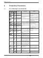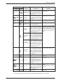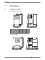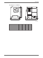
1
MITSUBISHI ELECTRIC
FR-S 500
Frequency Inverter
Installation Manual
FR-S 520 S
FR-S 540 EC/ECR
Art.-No:129918
10 02 2004
Version C
MITSUBISHI ELECTRIC
INDUSTRIAL AUTOMATION
About this Manual
The texts, illustrations, diagrams, and examples contained in this manual are
only intended as aids to help explain the installation, set-up, and starting of the
frequency inverters FR-S 520S EC/ECR and FR-S 540 EC/ECR.
If you have any questions concerning the programming and operation of the
equipment described in this manual, please contact your relevant sales office
or department (refer to back of cover).
Current information and answers to frequently asked questions are also
available through the Internet (www.mitsubishi-automation.com).
MITSUBISHI ELECTRIC EUROPE B.V. reserves the right to make
changes both to this manual and to the specifications and design of the
hardware at any time without prior notice.
Installation Manual
FR-S 520S EC/ECR und FR-S 540 EC/ECR
Art. No:129918
Version
Changes / Additions / Corrections
A
07/01
pdp
First issue
B
04/02
pdp
New rated currents for FR-S 540 EC/ECR
C
02/04
pdp – gb
General:
2
Introduction of the overload capacity
MITSUBISHI ELECTRIC
1
Introduction
1.1
General Description . . . . . . . . . . . . . . . . . . . . . . . . . . . . . . . . . . . . . . . . . . . . . . . . .7
2
Specifications
2.1
Model Specifications . . . . . . . . . . . . . . . . . . . . . . . . . . . . . . . . . . . . . . . . . . . . . . . . .8
3
Appearance and Structure
3.1
Description of the Case . . . . . . . . . . . . . . . . . . . . . . . . . . . . . . . . . . . . . . . . . . . . .11
4
Wiring
4.1
Overview . . . . . . . . . . . . . . . . . . . . . . . . . . . . . . . . . . . . . . . . . . . . . . . . . . . . . . . . .12
4.2
Wiring of the Main Circuit . . . . . . . . . . . . . . . . . . . . . . . . . . . . . . . . . . . . . . . . . . . .13
4.3
Wiring of the Control Circuit . . . . . . . . . . . . . . . . . . . . . . . . . . . . . . . . . . . . . . . . . .16
5
Parameter
5.1
Overview and Setting Ranges . . . . . . . . . . . . . . . . . . . . . . . . . . . . . . . . . . . . . . . .18
6
Protective Functions
6.1
Error Messages and Remedies . . . . . . . . . . . . . . . . . . . . . . . . . . . . . . . . . . . . . . .24
7
Dimensions
7.1
Frequency Inverters . . . . . . . . . . . . . . . . . . . . . . . . . . . . . . . . . . . . . . . . . . . . . . . .27
FR-S 500 EC/ECR
3
Safety Instructions
For qualified staff only
This manual is only intended for use by properly trained and qualified electrical technicians who
are fully acquainted with automation technology safety standards. All work with the hardware
described, including system design, installation, setup, maintenance, service and testing, may
only be performed by trained electrical technicians with approved qualifications who are fully acquainted with the applicable automation technology safety standards and regulations. Any operations or modifications of the hardware and/or software of our products not specifically
described in this manual may only be performed by authorised Mitsubishi staff.
Proper use of equipment
The devices of the FR-S series are only intended for the specific applications explicitly described in this manual. Please take care to observe all the installation and operating parameters
specified in the manual. The design, manufacturing, testing and documentation of these products have all been carried out in strict accordance with the relevant safety standards. Under normal circumstances the products described here do not constitute a potential source of injury to
persons or property provided that you precisely observe the instructions and safety information
provided for proper system design, installation and operation. However, unqualified modification of the hardware or software or failure to observe the warnings on the product and in this
manual can result in serious personal injury and/or damage to property. Only accessories specifically approved by MITSUBISHI ELECTRIC may be used with the frequency inverters
FR-S 520S EC/ECR und FR-S 540 EC/ECR. Any other use or application of the products is
deemed to be improper.
Relevant safety regulations
All safety and accident prevention regulations relevant to your specific application must be
observed in the system design, installation, setup, maintenance, servicing and testing of these
products.
The regulations listed below are particularly important. This list does not claim to be complete;
however, you are responsible for knowing and applying the regulations applicable to you.
쎲
VDE/EN Standards
– VDE 0100
(Regulations for electrical installations with rated voltages up to 1,000V)
– VDE 0105
(Operation of electrical installations)
– VDE 0113
(Electrical systems with electronic equipment)
– EN 50178
(Configuration of electrical systems and electrical equipment)
쎲 Fire prevention regulations
쎲
Accident prevention regulations
– VBG No. 4 (electrical systems and equipment)
4
MITSUBISHI ELECTRIC
General safety information and precautions
The following safety precautions are intended as a general guideline for using the frequency inverter together with other equipment. These precautions must always be observed in the design, installation and operation of all control systems.
P
E
DANGER:
쎲 Observe all safety and accident prevention regulations applicable to your specific
application. Installation, wiring and opening of the assemblies, components and
devices mayonly be performed with all power supplies disconnected.
쎲
Assemblies, components and devices must always be installed in a shockproof
housing fitted with a proper cover and protective equipment.
쎲
Devices with a permanent connection to the mains power supply must be integrated in the building installations with an all-pole disconnection switch and a suitable fuse.
쎲
Check power cables and lines connected to the equipment regularly for breaks
and insulation damage. If cable damage is found, immediately disconnect the
equipment and the cables from the power supply and replace the defective cabling.
쎲
Before using the equipment for the first time check that the power supply rating
matches that of the local mains power.
쎲
Residual current protective devices pursuant to DIN VDE Standard 0641 Parts 1–3
are not adequate on their own as protection against indirect contact for installations with frequency inverter systems. Additional and/or other protection facilities are essential for such installations.
쎲
EMERGENCY OFF facilities pursuant to VDE 0113 must remain fully operative at
all times and in all control system operating modes. The EMERGENCY OFF facility
reset function must be designed so that it cannot cause an uncontrolled or undefined restart.
쎲
You must also implement hardware and software safety precautions to prevent
the possibility of undefined control system states caused by signal line cable or
core breaks.
CAUTION:
All relevant electrical and physical specifications must be strictly observed and
maintained for all the frequency inverters in the installation.
The load used should be a three-phase induction motor only. Connection of any
other electrical equipment to the inverter output may damage the equipment.
FR-S 500 EC/ECR
5
Safety warnings
In this manual special warnings that are important for the proper and safe use of the products are
clearly identified as follows:
6
P
DANGER:
Personnel health and injury warnings. Failure to observe the precautions described
here can result in serious health and injury hazards.
E
CAUTION:
Equipment and property damage warnings. Failure to observe the precautions described here can result in serious damage to the equipment or other property.
MITSUBISHI ELECTRIC
Introduction
1
Introduction
This Installation Manual includes a brief summary of the main specifications of the FR-S 500 frequency inverters, which should be sufficient to enable experienced users to install and configure
the inverter. For further information on the functions and parametrization please refer to the Instruction Manual of the frequency inverter FR-S 500. This Installation Manual is intended exclusively as an installation and setup guide and a brief reference. It does not replace the main
product manual.
1.1
General Description
The frequency inverters are available with outputs from 0.2 to 1.5kW for operation with single-phase 200 to 240V AC power supply (FR-S 520S EC/ECR) or 0.4 to 3.7kW with three-phase
380 to 480V AC power supply (FR-S 540 EC/ECR). The frequency range is from 0.5 to 120Hz.
Features of the frequency inverters
쎲 Communication ability and networking
In the FR-S 500 ECR the comprehensive functions of the EC series are complemented by
a serial interface (RS485) installed as standard equipment. This enables communication
both with a personal computer and with a PLC, which can be networked with up to 31 other
devices with RS485 interface.
쎲 Compatibility with a lot of new applications
– PID Control
The inverter can be used to exercise process control, e.g. flow rate for pumps
– Stop function selection (terminal MRS)
This function is used to select the stopping method (deceleration to a stop or coasting).
쎲 Large number of protective functions for safe operation
– Automatic restart after instantaneous power failure
The inverter can be started without stopping the motor (with the motor coasting).
– Built-in overcurrent protection
– Retry function after alarm occurence
쎲 Compatible with numerous I/Os
– Multi-speed setting
15 different pre-selected speeds are available
– Control input for 0/4–20mA (0–10V)
– 4 Multi-input terminals
Selection of different input variations from 14 different input types (e.g. digital motor
potentiometer)
– Multi-output terminals (1 Relais, 1 Transistor with open collector)
Selection of 2 different output variations from 12 different output types
– 24V power supply output (24V DC/0.1A) for external devices
쎲 Automatic torque boost
FR-S 500 EC/ECR
7
Specifications
2
Specifications
2.1
Model Specifications
FR-S 520S EC/ECR
FR-S 540 EC/ECR
Type
0.2k
0.4k 0.75k
1.5k
0.4k
0.75k
1.5k
2.2k
3.7k
0.2
0.4
0.75
1.5
0.4
0.75
1.5
2.2
3.7
Rated output capacity [kVA]
0.5
1.0
1.6
2.8
0.9
1.6
2.7
3.7
5.9
Rated current [A]*
200% Overload capacity
1.4
2.5
4.1
7.0
Rated motor capacity [kW] �
Output
200 % Overload capacity
200% of rated motor capacity for 0.5s; 150% for 1min.
(max. ambiente temperature 50°C)
Overload capacity �
Input
Voltage �
3-phase, 0V up to power supply voltage
Power supply voltage
single-phase, 200–240V AC
3-phase, 380–480V AC
Voltage range
170–264V AC at 50 / 60Hz
325–528V AC at 50 / 60Hz
50 / 60Hz ± 5%
Frequency range
Rated input capacity [kVA] �
0.9
1.5
2.5
50 / 60Hz ± 5%
4.4
Protective structure
1.5
2.5
Self-cooling
Weight [kg]
0.6
0.8
Control method
1.0
Fan
cooling
1.5
Self-cooling
1.5
1.5
Sinusoidal PWM, Soft PWM
Switching frequency
0.7–14.5kHz, user adjustable
Frequency characteristics
analog
Frequency precision
9.5
Fan cooling
1.5
1.6
1.7
0.5–120Hz
From terminals 2-5: 1/500 of maximum set frequency (input 5V DC);
1/1000 (input 10V, 20mA DC)
±1% of max. output frequency (temperature range 25°C ± 10°C)
during analog input;
±0.5% of max. output frequency during digital input (set via Digital Dial)
≥ 150% / 6Hz (with automatic torque boost))
Possible starting torque
Acceleration / deceleration time
Acceleration / deceleration
characteristics
0; 0.1 to 999s (may be set individually for acceleration and deceleration)
Linear or S-pattern acceleration/deceleration mode selectable
Regenerative
Braking torque �
5.5
V/f control
Modulation control
Frequency
resolution
4.5
IP 20
Cooling
Control specifications
1.2 (1.3) 2.3 (2.5) 3.7 (4.1) 5.3 (5.8) 7.7 (8.5)
DCbraking
0.2k: 150%; 0.4k and 0.75k: 100%; 1.5k: 50%,
2.2k and 3.7k: 20%
Braking time and braking moment adjustable,
Operating frequency: 0–120Hz, operating time: 0–10s,
voltage: 0–15% (externally adjustable)
* The values in brackets indicate the values for an ambient temperature up to 40°C without restriction of PWM.
Please observe the notes on page 10!
8
MITSUBISHI ELECTRIC
Specifications
FR-S 520S EC/ECR
FR-S 540 EC/ECR
Type
0.2k
Frequency
setting signal
Analog
imput
Input signals
1.5k
2.2k
3.7k
The error indication (alarm signal )is reset with the reset
of the protective function 햽
Up to 15 speeds can be preset in the range of 0–120Hz. The current speed
can be adjusted during operation via the control panel. 햽
2nd function
Selects 2nd function (acceleration time, deceleration time, torque boost,
base frequency, electronic overcurrent protection) 햽
Output stop
Instant cutoff of inverter output (frequency and voltage) 햽
Selection of current input
External thermal input
Frequency setting via current input signal 0/4 to 20mA DC (Terminal 4) 햽
Stopping the inverter with an externally mounted thermal relay 햽
Select Jog operation 햽
JOG operation
Select PID control 햽
PID control
Switch between the operating modes “PU” and “External” 햽
PU <-> External operation
Operation functions
Output signals
0.75k
Control panel
Error reset
Control signals for operation
0.4k
Individual selection of forward / reverse run
Start signal self retaining input. 햽
Starting signal STF, STR
Maximum and minimum frequency setting, frequency jump operation, external thermal input selection, instantaneous power failure restart operation, forward run/reverse run prevention, slip compensation, operation
mode selection, PID-control, Computer link operation (RS485) 햷
Operation status 햾
1 output type (open collector output) selectable: Inverter running, frequency
reached, frequency detection, overload warning, zero return detection, output current detection, minimum PID, maximum PID, PID forward run, PID
reverse run, operation ready, minor failure and error,
1 relay contact can be selected for the output (230V AC;
0.3A / 30V DC; 0.3A)
Analog signal
One of the following output types can be selected: Output frequency, motor
current, analog output (0–5V DC with 1mA full scale).
Protection functions
Environment
1.5k
0–5V DC, 0–10V DC, 0/4–20mA
Digital
Multi-speed selection
0.4k 0.75k
Overcurrent (during acceleration, deceleration, constant speed),
overload cutoff in internal converter (during acceleration, deceleration,
constant speed),
Overload (motor/inverter), fin overheating, fan error �, Overcurrent cutoff,
ground fault during start �, external motor protection signal �,
PU connection error �, no. of retries; communications error �, CPU error,
undervoltage 햻
Ambient temperature
−10°C to +50°C (non freezing)
Storage temperature
−20°C to +65°C
Ambient humidity
Ambience condition
Max. 90% RH (non-condensing)
For indoor use only, avoid environments containing corrosive gases, no oil
mist, install in a dust-free location
Altitude
Vibration resistance
Max. 1000m above n.N.
Max. 0.6G
Please observe the notes on page 10!
FR-S 500 EC/ECR
9
Specifications
NOTES
Special notes referring to the table:
햲
햳
햴
햵
햶
햷
햸
햹
햺
햻
햽
햾
10
The applicable motor capacity refers to a motor voltage of 230V (FR-S 520S) resp. 440V
(FR-S 540).
The overload capacity indicated in % is the ratio of the overload current to the inverter’s rated
current. For repeated duty, allow time for the inverter and motor to return to or below the temperatures under 100% load.
The maximum output voltage cannot exceed the power supply voltage. The maximum output
voltage may be set as desired below the power supply voltage.
The power supply capacity changes with the values of the power supply side inverter impedances (including those of the input reactor and cables).
The braking torque indicated is short-duration average torque (which varies with motor
loss) when the motor alone is decelerated from 50Hz in the shortest time and is not a continuous regenerative torque.
When the motor is decelerated from the frequency higher than the base frequency, the average deceleration torque will reduce. Since the inverter does not contain a brake resistor,
use the optional brake resistor when regenerative energy is large. A brake unit BU may also
be used.
Only valid for frequency inverters equipped with an RS485 interface.
Only valid for frequency inverters equipped with a cooling fan.
To activate the function, set parameter 40 to “1”.
The input OH is activated by the parameters on the function assignment of the input terminals (Pr. 60 to Pr. 63).
When undervoltage or instantaneous power failure has occurred, alarm display or alarm
output is not provided but the inverter itself is protected. Overcurrent, regenerative
overvoltage, or other protection may be activated at power restoration according to the operating condition.
The input terminal function selection is made with parameters 60–63.
The output terminal function selection is made with parameters 64–65.
MITSUBISHI ELECTRIC
Appearance and Structure
3
Appearance and Structure
3.1
Description of the Case
Depending on the capacity class the frequency inverter is delivered in second different structural shapes of the case. The following drawings show a structured view of the single case components.
Frequency inverter FR-S 500 EC/ECR with front cover
Status display
MITSUBISHI
S500
RUN
PU
LED display
PU
EXT
EXT
Operation panel
RUN
STOP
RESET
Digital Dial
MODE
SET
Front cover
Rating plate
Wiring cover
FR-S520-1.5K
XXXXXX
Model type
Frequency inverter FR-S 500 EC/ECR without front cover
Connector only for
manufactorer use
RUN
PU
PU
EXT
EXT
RUN
+
-
STOP
RESET
RS485 or PU connector
SINK
SET
SOURCE
A B C
SD
STR
RL
RM
RH
AM
Sink-source logic
change-over jumper
Alarm output
PC
SE
RUN
10
2
5
4
MODE
Control circuit
terminal block
Main circuit
terminal block
Wiring cover
E
CAUTION:
The connector above the LED display is for manufacturer use. Do not touch it as doing so may cause an electric shock.
FR-S 500 EC/ECR
11
Wiring
4
Wiring
4.1
Overview
E
CAUTION:
The terminals PC-SD of the 24V DC power supply must not be shorted. Otherwise the
inverter will be damaged.
Motor
Main supply
FR-S 520S: 1-phase
FR-S 540: 3-phase
I>
I>
24V DC Output
Reference point for control inputs
Control inputs
Start forward
Start reverse
1. Multispeed setting
2. Multispeed setting
3. Multispeed setting
Reference potential
L1
N
U
V
W
PC
STF
STR
RH
RM
RL
SD
P1
�
DC choke coil
FR-BEL (Option)
�
�
�
+
−
�
SINK
A
B
C
�
Analog frequency setting
SOURCE
Setting
value
signal
1kΩ/2 W
3
2
1
10 (+5V)
5V DC
2 0–
0–10V DC
5 �
RUN
SE
AM
5
Current input (−)
0/4–20mA DC (+)
M
4
�
�
�
Jumper must be removed if
a DC choke coil is connected!
Alarm
OpenCollectoroutputs
� Operation
Reference potential
(+)
(-)
Analog output
signal
0–5V DC
�
RS485 interface
(e.g. for control
panel)
쐃 FR-S 500 ECR with RS485 interface only
쐇 The terminals SD und 5 are reference potentials. They must not be grounded.
쐋 Jumper for switching between sink and source.
쐏 Possible function assignments of the input terminals by parameter 60 to 63:
RL, RM, RH, RT, AU, STOP, MRS, OH, REX, JOG, RES, X14, X16 and (STR).
쐄 Possible function assignments of the output terminals by parameter 64 to 65:
RUN, SU, OL, FU, RY, Y12, Y13, FDN, FUP, RL, LF and ABC.
12
MITSUBISHI ELECTRIC
Wiring
4.2
P
E
4.2.1
Wiring of the Main Circuit
DANGER:
The frequency inverter must always be powered off completely before performing
any wiring work. Before starting rewiring or other work after performing operation
once, check the voltage with a meter etc. more than 10 minutes after power-off. For
some time after power-off, there is a dangerous voltage in the capacitor.
CAUTION:
Power must not be applied to the output terminals (U, V, W) of the inverter. Otherwise
the inverter will be damaged.
The inverter must be grounded using the dedicated ground terminal.
Mains, Motor and Ground Terminal Connections
The terminal blocks for connection of the frequency inverter can be accessed by removing the
front cover and the wire cover. Connect a 1-phase power supply to the terminals L1 and N when
using the inverter FR-S 520S EC/ECR and a 3-phase power supply to the terminals L1, L2 and
L3 when using the inverter FR-S 540 EC/ECR. The required power supply is 200–240V AC,
−15% / +10% for the inverter type FR-S 520S EC/ECR and 380–480V AC for the inverter type
FR-S 540 EC/ECR. The mains frequency is 50–60Hz ± 5% for all types.
Connect the motor cables to terminals U, V and W. The illustration below shows the correct assignments for the power connections. The required cable size is 1.5mm² up to the capacity class
0.75k and 2.5mm² for higher capacity classes.
NOTE
The inverter must be grounded using the dedicated ground terminal.
1-phase power supply
FR-S 520S EC/ECR
3-phase power supply
FR-S 540 EC/ECR
N
R/L
S/L
T/L3
U
V
W
Power
supply
terminals
Ground
terminal
FR-S 500 EC/ECR
13
Wiring
NOTE
It is recommended to use a shielded motor cable in order to reduce cable radiation.
1-phase power
supply
3-phase power
supply
Q1
Q1
L1
I
L1
U
L1
I
L1
N
I
N
V
L2
I
L2
V
W
L3
I
L3
W
U
−
−
P1
P1
+
+
PE
PE
NOTE
FR-S 540 EC/ECR
FR-S 520 S EC/ECR
The maximum wiring length of the motor cable ist 100m. When automatic torque boost is selected in Pr. 98, the maximum wiring lenght is 30m.
Main circuit connector
The following table shows the terminal assignment of main circuit terminals.
Terminal
Terminal name
L1, N
L1, L2, L3
Mains supply connection
+, −
External brake unit connection
An external brake unit can be connected to the terminals + and −.
P1, +
DC choke coil
connection
An optional choke coil can be connected to the terminals P1 and +.
Disconnect the jumper before connecting the
choke coil.
U, V, W
Motor connection
Voltage output of the inverter (3-phase, 0V up to
power supply voltage, 0.5–120Hz)
PE
E
14
Description
Mains power supply of the inverter
Protective earth connection of inverter
CAUTION:
Switching the unit off and on repeatedly with the mains power supply at short intervals can damage the switch-on current limiter. Because of this the unit should always
be started and stopped with the control unit or via the STF/STR and STOP control signals.
MITSUBISHI ELECTRIC
Wiring
4.2.2
Main Circuit Terminals
FR-S 520S-0.2k to 0.75k EC/ECR
L1
N
-
P1
+
U
V
W
M
Motor
Power supply
Screw size: M3.5
Screw tightening torque: 1.2Nm
FR-S 520S-1.5 k EC/ECR
Jumper
-
+
P1
L1
N
U
Power supply
V
W
M
Motor
Screw size: M4
Screw tightening torque: 1.5Nm
FR-S 540-0.4 k to 3.7 k EC/ECR
Jumper
-
+
P1
L1 L2
L3
Power supply
U
V
M
W
Motor
Screw size: M4
Screw tightening torque: 1.5Nm
FR-S 500 EC/ECR
15
Wiring
4.3
Wiring of the Control Circuit
The following picture shows the arrangement of the terminal for the control circuit of the inverter.
PE
SE
RUN
10
2
5
4
RUN
PU
PU
EXT
EXT
SD
RUN
A
+
-
B
SD
STF STR
RL
RM
RH
AM
C
STOP
RESET
SET
PC
SE
RUN
10
2
5
4
MODE
SINK
A B C
Signal
Terminal
Contact input
Terminal name
Forward rotation start
Reverse rotation start
The motor rotates reverse, if a signal
is applied to terminal STR.
When the STF and STR signals are
turned on simultaneously, the stop
command is given.
RH, RM, RL
Multi-speed selection
Up to 15 different output frequencies
can be preset; for the speed commands the following priorities apply:
Jog, speed selection (RH, RM, RL,
RX) and AU.
SD �
Common sink for contact input/reference potential
A determined control function is activated, if the corresponding terminal is connected to the terminal SD. The
SD terminal is isolated from the digital circuits via
optocouplers.
The terminal is isolated from the terminals 5 and SE.
PC �
24V DC output and common
source for contact input/reference potential
24V DC / 0.1A output via PC-SD
In sink logic, when activated by open collector transistors
(e.g. PLC) the positive pole of an external power supply
has to be connected to the PC terminal.
In source logic, the PC terminal serves as common reference point for the control inputs.
10
(output voltage 5V DC)
Voltage output for
potentiometer
2
Input for frequency settingvalue signal
The voltage setting value 0–5 (10) V is applied to this terminal. The voltage range is preset to 0–5V.
(Parameter 73). The input resistance is 10kΩ; The maximum permitted voltage is 20V.
5
Reference point for frequency
setting value signal
Terminal 5 is the reference point for all analog setting values (Terminal 2 and 4) and for the analog output signal
AM. The terminal is not isolated from the terminals SD
and SE and must not be earthed.
4
Input for current
setting value signal
0/4–20mA DC
The current setting value signal (0/4–20mA DC) is applied to this terminal. The input is active only if the AU signal is set. The function of the AU signal is assigned via
parameters 60 to 63. The input resistance is 250Ω, the
max current is 30mA. By default, this signal is set to 0Hz at
4mA and 50Hz at 20mA.
STR
Common
Setting value specification
Analog
16
Description
The motor rotates forward, if a signal is applied to terminal STF.
When the STF and STR signals are turned on simultaneously, the stop command is given.
STF
Input signals
SD
STR
RL
RM
RH
AM
SOURCE
Input ter minal
function selection (Pr. 60 to Pr.
63) changes the
terminal functions. �
Output voltage 5V DC
Max. output current 10mA.
Recommended potentiometer: 1kΩ, 2W linear,
multiturn potentiometer
MITSUBISHI ELECTRIC
Wiring
Signal
Terminal
Terminal name
Description
햳
햴
햵
E
Open Collector
RS485
Commun.
햲
A, B, C
Potential free
alarm output
B
A
C
The maximum contact load is 230V /
0.3A AC or 30V / 0.3A DC.
Analog
Output signals
Contact
The alarm is output via relay contacts. The block diagram shows the
normal operation and voltage free
status. If the protective function is activated, the relay picks up.
RUN
Signal output for
motor operation
SE
Reference potential for
signal outputs
AM
—
Analog output
Connection of control panel
(RS485) �
Output terminal
function selection
(Pr. 64, Pr. 65)
changes the terminal functions.�
The output is switched low, if the inverter output frequency is equal to
the starting frequency. The output is
switched high, if no frequency is output or the DC brake is in operation.
The maximum contact load is
24V DC / 0.1A.
Reference potential for the signal RUN. This terminal is
isolated from the reference potential of the control circuit
5 and SD.
One of the following monitoring functions can be selected: external frequency output or motor current output.
A DC voltmeter can be connected.
Factory setting of
output item:
Frequency Output
signal 0 to 5VDC
Permissible load
current 1mA
Using the parameter unit connection cable the parameter unit (FR-PU04) is connectable.
Communication operation can be performed through
RS-485.
I/O standard: RS485, Multi-Drop operation,
max. 19200 Baud, Overall length max. 500m
The following function assignments are supported: RL, RM, RH, RT, AU, STOP, MRS, OH,
REX, JOG, RES, X14, X16, and (STR).
The terminals PC and SD must not be connected to each other nor to the protective earth
terminal.
In source logic, the terminal PC serves as common reference point for the control inputs.
In sink logic, the terminal SD serves as common reference point for the control inputs.
The following function assignments are supported: RUN, SU, OL, FU, RY, Y12, Y13, FDN,
FUP, RL, LF, and ABC.
The RS485-connector is optional.
CAUTION:
Terminals 10 and 5 must not be connected to each other. Otherwise the internal voltage output for the connection of the potentiometer will be damaged.
FR-S 500 EC/ECR
17
Parameter
5
Parameter
5.1
Overview and Setting Ranges
Function
Basic
functions
Parameter Meaning
Setting range
Default
0
Torque boost (manual)
0–15%
4/5/6% �
1
Maximum frequency
0–120Hz
2
Minimum frequency
0–120Hz
0Hz
3
Base frequency
0–120Hz
50Hz
4
Multi-speed setting (high speed) �
0–120Hz
50Hz
5
Multi-speed setting (middle speed) �
0–120Hz
30Hz
6
Multi-speed setting (low speed) �
0–120Hz
10Hz
7
Acceleration time
0–999s
5s
8
Deceleration time
0–999s
5s
9
Electronic thermal overload relay
0–50A
Rated
current
30
Extended function display selection �
0: No display
1: Display
0
79
Operation mode selection
0–4 / 7 / 8
0
50Hz
The extended function parameters are made valid by setting “1” in Pr. 30.
Parameters for
standard
drive
operation
10
DC injection brake operation frequency
0–120Hz
3Hz
11
DC injection brake operation time
0–10s
0.5s
12
DC injection brake voltage
0–15%
6%
13
Starting frequency
0–60Hz
0.5Hz
14
Load pattern selection
0:
1:
2:
3:
15
JOG frequency
0–120Hz
5Hz
16
JOG acceleration / deceleration time
0–999s
0.5s
17
RUN key rotation direction selection
0: forward rotation
1: reverse rotation
19
Max. output voltage
0–500 (800)�V / 888 / ---
20
Acceleration / deceleration reference
frequency
1–120Hz
21
Acceleration / deceleration time increments
0–31 / 100
22
Stall prevention operation level �
0–200%
23
Stall prevention operation at double speed
0–200% / ---
---
24
0–120Hz / ---
---
0–120Hz / ---
---
26
Multi-speed setting (speed 4) �
Multi-speed setting (speed 5) �
Multi-speed setting (speed 6) �
0–120Hz / ---
---
27
Multi-speed setting (speed 7) �
0–120Hz / ---
28
Multi-speed input compensation
0–120Hz
29
Acceleration / deceleration pattern
0: Linear acceleration/
deceleration,
1: S-pattern acceleration/
deceleration A,
2: S-pattern acceleration/
deceleration B
0
31
Frequency jump 1A
0–120Hz / ---
---
32
Frequency jump 1B
0–120Hz / ---
---
33
Frequency jump 2A
0–120Hz / ---
---
34
Frequency jump 2B
0–120Hz / ---
---
25
18
For constant-torque loads,
For variable-torque loads,
For vertical lift loads,
For vertical lift loads
0
0
888
50Hz
0
150%
--50Hz
MITSUBISHI ELECTRIC
Parameter
Function
Standard
operation
functions
Output terminal functions
Second
functions
Current
detection
Display
functions
Automatic
restart
functions
Additional
function
FR-S 500 EC/ECR
Parameter Meaning
Setting range
Default
35
Frequency jump 3A
0–120Hz / ---
---
36
Frequency jump 3B
0–120Hz / ---
---
37
Speed display
0 / 0.1–999
38
Frequency at 5V (10V) input voltage
1–120Hz
50Hz
39
Frequency at 20mA input current
1–120Hz
50Hz
40
Start-time ground fault detection selection
0: Not detected
1: Detected
41
Setting value / current value comparison
(SU output)
0–100%
10%
42
Output frequency monitoring (FU output)
0–120Hz
6Hz
43
Output frequency detection for reverse rota0–120Hz / --tion
---
0
1
44
Second acceleration/deceleration time
0–999s
5s
45
Second deceleration time
0–999s / ---
---
46
2. Manual torque boost
0–15% / ---
---
47
Second V/F (base frequency)
0–120Hz / ---
48
Output current detection level
0–200%
49
Output current detection signal delay time
0–10s
0s
50
Zero current detection level
0–200%
5%
51
Zero current detection time
0.05–1s
0.5s
52
Control panel display data selection �
0: Output frequency,
1: Output current,
100: Set frequency
during stop/output
frequency during
operation
0
53
Digital Dial function selection �
0: Setting dial
frequency setting
1: Setting dial:
potentiometer mode
0
54
Output AM terminal �
0: Output frequency
monitor
1: Output current
monitor
0
55
Frequency monitoring reference �
0–120Hz
56
External current monitoring reference �
0–50A
57
Restart coasting time after power failure
0–5s / ---
---
58
Restart cushion time before automatic
synchronisation
0–60s
1s
Selection of digital motor potentiometer
0: Without remote setting
function
1: With remote setting
function
With frequency setting
storage function
2: With remote setting
function
Without frequency
setting storage function
0
59
--150%
50Hz
Rated
current
19
Parameter
Function
Parameter Meaning
60
RL terminal function selection
Setting range
0:
1:
2:
3:
4:
61
RM terminal function selection
5:
6:
7:
62
RH terminal function selection
8:
9:
10:
14:
Terminal
function
selection
63
STR terminal function selection
16:
---:
0:
64
RUN terminal function selection
1:
3:
4:
11:
12:
13:
65
ABC terminal function selection
14:
15:
16:
98:
99:
RUN (RUN terminal
function selection)
SU (up to frequency)
OL (overload alarm)
FU (output frequency
detection)
RY (inverter operation
ready)
Y12 (output current
detection)
Y13 (zero current
detection)
FDN (PID lower limit)
FUP (PID upper limit)
RL (PID forward-reverse
rotation output)
LF (minor fault output)
ABC (Alarm output)
Default
0
1
2
---
0
99
Retry selection
0: OC1 to 3, OV1 to 3,
THM, THT, GF,
OHT, OLT, PE, OPT
1: OC1 to 3,
2: OV1 to 3,
3: OC1 to 3, OV1 to 3
0
67
Number of restart retries
0: No retry
1–10:
Without alarm
output during
retry operation
101–110:
With alarm output
during retry operation
0
68
Waiting time for automatic restart retry
0.1–360s
1s
69
Retry count display erase
0: Cumulative count erase
0
70
Soft-PWM setting�
0: Soft-PWM invalid,
1: Soft-PWM valid
1
Motor selection
0: Thermal characteristic
matching a standard motor
1: Thermal characteristic
matching a Mitsubishi
constant-torque motor
0
66
Operation
selection
functions
71
20
RL (low speed)
RM (middle speed)
RH (high speed)
RT (second function
selection)
AU (current input
selection)
STOP (start self-holding
selection)
MRS (output shut-off
stop)
OH (external thermal
relay input)
REX (15-speed
selection)
JOG (jog operation
selection)
RES (RESET)
X14 (PID control
presence/absence
selection)
X16 (PU-external
operation switch-over)
-: STR (May be assigned
to the STR terminal only)
MITSUBISHI ELECTRIC
Parameter
Function
Parameter Meaning
Setting range
Default
72
PWM frequency selection �
0–15
0: 0.7kHz
15: 14.5kHz
73
Specification of setting value input data
0: 0–5V DC
1: 0–10V DC
0
74
Setting value signal filter
0–8
1
1
0:
Reset selection/PU stop �
Reset normally
enabled/PU stop key
disabled
1: Enabled at alarm
occurrence only/PU
stop key disabled
14: Reset normally
enabled/normally
decelerated to stop
15: Enabled at alarm
occurrence
only/normally
decelerated to stop
14
Cooling fan operation selection
0: Operation started at
power-on
1: Cooling fan ON/OFF
control
1
Parameter write disable selection �
0: Write is enabled only
during a stop
1: Write disabled
(except some parameters)
2: Write during operation
enabled
0
78
Reverse rotation prevention selection
0: Both forward rotation
and reverse rotation
enabled,
1: Reverse rotation disabled,
2: Forward rotation disabled
0
80
8. Multispeed preset �
0–120Hz / ---
---
81
9. Multispeed preset �
0–120Hz / ---
---
82
10. Multispeed preset �
0–120Hz / ---
---
83
11. Multispeed preset �
0–120Hz / ---
---
84
12. Multispeed preset �
0–120Hz / ---
---
85
13. Multispeed preset �
0–120Hz / ---
---
86
14. Multispeed preset �
15. Multispeed preset �
0–120Hz / ---
---
0–120Hz / ---
--20
75
Operation
selection
functions
76
77
Multispeed
preset
87
PID
control
Slip compensation
Autom.
torque
boost
FR-S 500 EC/ECR
88
PID action selection
20: PID reverse action,
21: PID forward action
89
PID proportional band �
0.1–999% / ---
100%
90
PID integral time �
0.1–999s / ---
1s
91
PID upper limit
0–100% / ---
---
92
PID lower limit
0–100% / ---
---
93
PID action set point for PU operation �
0–100%
0%
94
PID differential time �
0.01–10s / ---
---
95
Rated motor slip
0–50% / ---
---
96
Slip compensation time constant
0.01–10s
97
Output region for slip compensation
0 / ---
---
98
Automatic torque boost (motor capacity)
0.1–3.7kW � / ---
---
99
Motor primary resistance constant A
0–50Ω / ---
---
0.5s
21
Parameter
Function
Calibration
functions
Clear
functions
Parameter Meaning
Setting range
Default
C1
(901) �
AM terminal calibration
Calibration range
C2
(902) �
Frequency setting voltage bias frequency
0–60Hz
0Hz
C3
(902) �
Frequency setting voltage bias
0–300%
0% �
C4
(903) �
Frequency setting voltage gain
0–300%
96% �
C5
(904) �
Frequency setting current bias frequency
0–60Hz
0Hz
C6
(904) �
Frequency setting current bias
0–300%
20% �
C7
(905) �
Frequency setting current gain
0–300%
100% �
C8
(269) �
Parameter set by manufacturer: Do not set!
—
CLr
Clear parameter
0: Do not clear parameter
1: Clear parameter
10: Clear all parameters
0
ECL
Clear alarm history �
0: Do not clear alarm history
1: Clear alarm history
0
Parameters only for the type having the RS-485 communication function
(When the parameter unit (FR-PU04) is used, operation from the operation panel is not accepted.)
Communication
functions
n1
(331) �
Station number
0–31
n2
(332) �
Communication speed
48:
4800 Baud
96:
9600 Baud
192: 19200 Baud
n3
(333) �
Stop bit length / data length
0 / 1: Data length 8
10 / 11: Data length 7
1
n4
(334) �
Parity check
0: Absent
1: With odd parity check
2: With even parity check
2
n5
(335) �
Number of communication retries
0–10 / ---
1
n6
(336) �
Communication check time interval
0–999s / ---
---
n7
(337) �
Wait time setting
0–150ms / ---
---
Operation command write
0: Command write from
computer
1: Command write
from external terminal
0
n9
(339) �
Speed command write
0: Command write from
computer
1: Command write
from external terminal
0
n10
(340) �
Link start mode selection
0: As set in Pr. 79
1: Started in computer link
operation mode.
0
n8
(338) �
22
0
192
MITSUBISHI ELECTRIC
Parameter
Function
Communication
Parameters
Parameter Meaning
Setting range
Default
n11
(341) �
CR / LF selection
0: Without CR/LF
1: With CR, without LF
2: With CR/LF
n12
(342) �
E²PROM selection
0: Write to RAM and
E²PROM
1: Write to RAM only
0
n13
(145) �
PU display language
0:
1:
2:
3:
4:
5:
6:
7:
Japanese
English
German
French
Spanish
Italian
Swedish
Finish
1
n14
(990) �
PU buzzer sound control �
0: Without sound
1: With sound
1
n15
(991) �
PU contrast adjustment �
0 (bright) to 63 (dark)
58
0:
n16
(992) �
PU main display screen data selection �
Selectable between
output frequency and
output current
100: (during stop):
Set frequency, output
current
(during operation):
Output frequency,
output current
1
0:
n17
(993) �
PU disconnection detection /
PU setting lock
Without PU
disconnection error
1: Error at PU
disconnection
10: Without PU
disconnection error (PU
operation disable)
0
0
Remarks:
햲
햳
햴
햵
햶
햷
FR-S 500 EC/ECR
FR-S 520S EC/ECR and FR-S 540-0.4 to 0.75k = 6%, FR-S 540-1.5 to 2.2k = 5%,
FR-S 540-3.7k = 4%
Setting range FR-S 520S EC/ECR = 0–500V, FR-S 540 EC/ECR = 0–800V;
Value 888 = 95% of the power supply voltage
The settings of the parameters can be changed during operation, provided parameter 77 is
set to “0”. Parameters 53, 70, and 72 can only be changed during PU operation.
The values depend on the settings of the calibration parameters.
The parameter numbers in brackets are displayed by the parameter unit FR-PU04.
Setting range FR-S 520S EC/ECR = 0.1–3.7kW, FR-S 540 EC/ECR = 0.2–3.7kW
23
Protective Functions
6
Protective Functions
6.1
Error Messages and Remedies
Error message
Display
FR-PU04
LEDdisplay
Meaning
Description
Overcurrent1
(acceleration)
Overcurrent12
(const. speed.)
Overcurrent13
(deceleration)
Overvoltage 1
(acceleration)
Overvoltage 2
(const. Speed)
Overvoltage 3
(deceleration)
Corrupt
Memry
24
The converter voltage has increased highly due to regenerative energy. The overvoltage limit
was exceeded during acceleration, deceleration, or at constant
speed.
In most cases the protective function is activated due to a too short
deceleration time preset or a regenerative overload.
Increase the deceleration time by
connecting an external brake
unit.
An overvoltage in the mains
power supply activates this protective function as well.
Decrease the motor load to avoid
an activation.
Check whether the performance
range of the motor and inverter
correspond.
If the cooling fin overheats, the
fin overheat sensor activates
and halts inverter output.
Check ambient temperature.
Fin overheat
The cooling fan breaks down or
an operation different from the
setting of Pr. 76 is performed.
Replace cooling fan.
Fan breakdown
Check load connections
(motor circuit).
Ground fault
An overcurrent occured due to a
ground fault upon the inverter
output (load side). Made valid
when Pr. 40 “start-time ground
fault detection selection” = “1”.
An external motor protective
switch was activated. If an external motor protective switch for
thermal monitoring is used, this
switch can activate the protective function of the inverter.
Check motor load and drive.
Activation of an
external motor
protection relay
(thermal contact)
Stall prevention
overload
A long lasting excess of the current limit (OL display) shuts
down the inverter.
Communication
error
The protective function is activated, if a setting or connection
error occurs during serial communication
Check connections and connectors of the operating unit
Error on access of the data
memory of the inverter.
Please contact your nearest
MITSUBISHI ELECTRIC representative if the error occurs again.
Overload
(Inverter)
Ground
fault
B) The temperature of the main circuits of the inverter rises rapidly.
The cause for the activation of the
protective function is a short circuit or a ground fault across the
main outputs, an exceeding moment of inertia
Overcurrent 2 of the load (GD²),
too short acceleration/ deceleration time presets, restart during a
motor idling phase, operation of a
motor with an exceeding capacity.
Overheating due to insufficient
cooling (defective cooling fan or
choked heat sink).
The electronic overload protection for the motor or inverter was
activated. If a self-cooling motor
operates over a long period at
low speed but high torque, the
motor is thermally overloaded
and the protective function is activated.
Overload
(Motor)
Fn
A) The output current of the inverter has reached or exceeded
200% of the rated current during
acceleration, deceleration, or at
constant speed.
Remedy
Memory error
Reduce the load.
Check the preset values for the
current limit (Pr. 22) and the stall
prevention selection (Pr. 21).
MITSUBISHI ELECTRIC
Protective Functions
Error message
Meaning
Description
Remedy
Parameter unit
connection error
A connection error between inverter and external parameter
unit occurred during operation.
This alarm is only returned, if Pr.
17 is set to “1”.
Check the connection of the parameter unit.
Au t o m a t i c restar t retr y exceeded
After activation of a protective
function the inverter failed to be
restarted automatically within
the number of retries specified
in Pr. 67.
Remedy the actual cause of the
originary protective function.
CPU
Fault
CPU error
Failure on CPU printed circuit
board.
Contact the MITSUBISHI ELECTRIC customer service
I nve r t e r wa s
stopped via control panel or PU
STOP key on the control panel
or PU was pressed during external operating mode.
Check Pr. 75.
PS
Overcurrent
during
acceleration
If a current of more than 150 %�
of the rated inverter current
flows in the motor, this function
stops the increase of the frequency until the overload current reduces to prevent the inve r t e r f r o m r e s u l t i n g i n
overcurrent shut-off.
Change the acceleration/deceleration time. Increase the stall prevention operation level via Pr. 22.
Disable the stall prevention via Pr.
21. Check whether the torque
boost in Pr. 0 is set higher than required.
Overcurrent
during constant
speed
If a current of more than 150 %�
of the rated inverter current
flows in the motor, this function
lowers the frequency until the
overload current reduces to prevent the inverter from resulting
in overcurrent shut-off.
Overcurrent
during deceleration
If a current of more than 150 %
of the rated inverter current
flows in the motor, this function
stops the decrease of the frequency until the overload current reduces to prevent the inve r t e r f r o m r e s u l t i n g i n
overcurrent shut-off.
Increase the deceleration time
using Pr. 8 “deceleration time”.
Overvoltage
during
deceleration
If the regenerative energy of the
motor exceeds the brake capacity of the inverter, this function
stops the decrease of the frequency to prevent overvoltage
shut-off. When the regenerative
energy has reduced, deceleration resumes.
Undervoltage
The power supply voltage is too
low.
Check the power supply
voltage.
Write was performed with “1”
(write disable) set in Pr. 77 or
frequency jump setting range
overlapped or parameter write
was performed via the control
panel although it was not write
enabled.
Write was performed during operation or in the external operation mode or an attempt was
made to change the operation
mode set by an operation command via Pr. 79.
Check the settings of Pr. 77, 31 to
36, and n17.
Analog input bias and gain are
set too closely.
Check the settings of Pr. C3, C4,
C6, and C7.
Display
FR-PU04
PU Leave
Out
OL
oL
LEDdisplay
Write error
Write error
OPERATOR
ERR
Calibration error
햲
FR-S 500 EC/ECR
Stop operation before changing
settings.
Select PU (parameter unit) operation mode.
The current limit value (Pr. 22) can be changed. By default, it is set to 150%.
25
Dimensions
7
Dimensions
7.1
Frequency Inverters
FR-S 520S-0.2k to 0.75k EC/ECR
118
+
4
5
5
6
128
-
5
ø5
6
56
68
18,5
D2
D1
D
Unit: mm
Type
D
D1
D2
FR-S 520S-0.2k EC/ECR
80.5
10
52
FR-S 520S-0.4k EC/ECR
142.5
42
82
FR-S 520S-0.75k EC/ECR
162.5
62
82
FR-S 520S-1.5k EC/ECR
5
ø5
96
108
5
5
6
128
+
118
-
6
8
18,5
72
65
155,5
Unit: mm
26
MITSUBISHI ELECTRIC
Dimensions
FR-S 540-0.4k to 3.7k EC/ECR
5
ø5
96
108
5
5
6
128
+
118
-
D3
6
18,5
D2
D1
D
Unit: mm
Type
D
D1
D2
D3
FR-S 540-0.4k EC/ECR
129.5
59
52
5
FR-S 540-0.75k EC/ECR
129.5
59
52
5
FR-S 540-1.5k EC/ECR
135.5
65
52
8
FR-S 540-2.2k EC/ECR
155.5
65
72
8
FR-S 540-3.7k EC/ECR
165.5
65
82
8
FR-S 500 EC/ECR
27
MITSUBISHI ELECTRIC
HEADQUARTERS
EUROPEAN REPRESENTATIVES
EUROPEAN REPRESENTATIVES
EURASIAN REPRESENTATIVES
MITSUBISHI ELECTRIC
EUROPE
EUROPE B.V.
German Branch
Gothaer Straße 8
D-40880 Ratingen
Phone: +49 (0)2102 486-0
Fax: +49 (0)2102 486-1120
e mail: [email protected]
MITSUBISHI ELECTRIC
FRANCE
EUROPE B.V.
French Branch
25, Boulevard des Bouvets
F-92741 Nanterre Cedex
Phone: +33 1 55 68 55 68
Fax: +33 1 55 68 56 85
e mail: [email protected]
MITSUBISHI ELECTRIC
IRELAND
EUROPE B.V.
Irish Branch
Westgate Business Park, Ballymount
IRL-Dublin 24
Phone: +353 (0) 1 / 419 88 00
Fax: +353 (0) 1 / 419 88 90
e mail: [email protected]
MITSUBISHI ELECTRIC .
ITALY
EUROPE B.V
Italian Branch
Via Paracelso 12
I-20041 Agrate Brianza (MI)
Phone: +39 039 60 53 1
Fax: +39 039 60 53 312
e mail: [email protected]
MITSUBISHI ELECTRIC
SPAIN
EUROPE B.V.
Spanish Branch
Carretera de Rubí 76-80
E-08190 Sant Cugat del Vallés
Phone: +34 9 3 565 3131
Fax: +34 9 3 589 2948
e mail: [email protected]
MITSUBISHI ELECTRIC
UK
EUROPE B.V.
UK Branch
Travellers Lane
GB-Hatfield Herts. AL10 8 XB
Phone: +44 (0) 1707 / 27 61 00
Fax: +44 (0) 1707 / 27 86 95
e mail: [email protected]
MITSUBISHI ELECTRIC
JAPAN
CORPORATION
Office Tower “Z” 14 F
8-12,1 chome, Harumi Chuo-Ku
Tokyo 104-6212
Phone: +81 3 622 160 60
Fax: +81 3 622 160 75
MITSUBISHI ELECTRIC
USA
AUTOMATION
500 Corporate Woods Parkway
Vernon Hills, IL 60061
Phone: +1 847 478 21 00
Fax: +1 847 478 22 83
GEVA
AUSTRIA
Wiener Straße 89
AT-2500 Baden
Phone: +43 (0)2252 / 85 55 20
Fax: +43 (0)2252 / 488 60
e mail: [email protected]
TEHNIKON
BELARUS
Oktjabrskaya 16/5, Ap 704
BY-220030 Minsk
Phone: +375 (0)17 / 2104626
Fax: +375 (0)17 / 2275830
e mail: [email protected]
Getronics b.v.
BELGIUM
Control Systems
Pontbeeklaan 43
BE-1731 Asse-Zellik
Phone: +32 (0)2 / 467 17 51
Fax: +32 (0)2 / 467 17 45
e mail: [email protected]
TELECON CO.
BULGARIA
4, A. Ljapchev Blvd.
BG-1756 Sofia
Phone: +359 (0)2 / 97 44 058
Fax: +359 (0)2 / 97 44 061
e mail: —
INEA CR d.o.o.
CROATIA
Drvinje 63
HR-10000 Zagreb
Phone: +385 (0)1 / 3667140
Fax: +385 (0)1 / 3667140
e mail: —
AutoCont
CZECH REPUBLIC
Control Systems s.r.o.
Nemocnicni 12
CZ-70200 Ostrava 2
Phone: +420 59 / 6152 111
Fax: +420 59 / 6152 562
e mail: [email protected]
louis poulsen
DENMARK
industri & automation
Geminivej 32
DK-2670 Greve
Phone: +45 (0)43 / 95 95 95
Fax: +45 (0)43 / 95 95 91
e mail: [email protected]
UTU Elektrotehnika AS
ESTONIA
Pärnu mnt.160i
EE-10621 Tallinn
Phone: +372 (0)6 / 51 72 80
Fax: +372 (0)6 / 51 72 88
e mail: [email protected]
UTU POWEL OY
FINLAND
Box 236
FIN-28101 Pori
Phone: +358 (0)2 / 550 800
Fax: +358 (0)2 / 550 8841
e mail: [email protected]
UTECO A.B.E.E.
GREECE
5, Mavrogenous Str.
GR-18542 Piraeus
Phone: +302 (0)10 / 42 10 050
Fax: +302 (0)10 / 42 12 033
e mail: [email protected]
Meltrade Automatika Kft. HUNGARY
55, Harmat St.
HU-1105 Budapest
Phone: +36 (0)1 / 2605 602
Fax: +36 (0)1 / 2605 602
e mail: [email protected]
SIA POWEL
LATVIA
Lienes iela 28
LV-1009 Riga
Phone: +371 784 2280
Fax: +371 784 2281
e mail: [email protected]
UAB UTU POWEL
LITHUANIA
Savanoriu Pr. 187
LT-2053 Vilnius
Phone: +370 (0)52323-101
Fax: +370 (0)52322-980
e mail: [email protected]
Intehsis Srl
MOLDOVA
Cuza-Voda 36/1-81
MD-2061 Chisinau
Phone: +373 (0)2 / 562 263
Fax: +373 (0)2 / 562 263
e mail: [email protected]
Getronics b.v.
NETHERLANDS
Control Systems
Donauweg 2 B
NL-1043 AJ Amsterdam
Phone: +31 (0)20 / 587 6700
Fax: +31 (0)20 / 587 6839
e mail: [email protected]
Motion Control
NETHERLANDS
Automation b.v.
Markenweg 5
NL-7051 HS Varsseveld
Phone: +31 (0)315 / 257 260
Fax: +31 (0)315 / 257 269
e mail: —
Beijer Electronics AS
NORWAY
Teglverksveien 1
NO-3002 Drammen
Phone: +47 (0)32 / 24 30 00
Fax: +47 (0)32 / 84 85 77
e mail: [email protected]
MPL Technology Sp. z o.o. POLAND
ul. Sliczna 36
PL-31-444 Kraków
Phone: +48 (0)12 / 632 28 85
Fax: +48 (0)12 / 632 47 82
e mail: [email protected]
Sirius Trading & Services srl ROMANIA
Str. Biharia Nr. 67-77
RO-013981 Bucuresti 1
Phone: +40 (0) 21 / 201 1146
Fax: +40 (0) 21 / 201 1148
e mail: [email protected]
ACP Autocomp a.s.
SLOVAKIA
Chalupkova 7
SK-81109 Bratislava
Phone: +421 (02)5292-2254
Fax: +421 (02)5292-2248
e mail: [email protected]
INEA d.o.o.
SLOVENIA
Stegne 11
SI-1000 Ljubljana
Phone: +386 (0)1 513 8100
Fax: +386 (0)1 513 8170
e mail: [email protected]
Beijer Electronics AB
SWEDEN
Box 426
S-20124 Malmö
Phone: +46 (0)40 / 35 86 00
Fax: +46 (0)40 / 35 86 02
e mail: [email protected]
ECONOTEC AG
SWITZERLAND
Postfach 282
CH-8309 Nürensdorf
Phone: +41 (0)1 / 838 48 11
Fax: +41 (0)1 / 838 48 12
e mail: [email protected]
GTS
TURKEY
Darülaceze Cad. No. 43A KAT: 2
TR-80270 Okmeydani-Istanbul
Phone: +90 (0)212 / 320 1640
Fax: +90 (0)212 / 320 1649
e mail: [email protected]
CSC Automation
UKRAINE
15, M. Raskova St., Fl. 10, Off. 1010
UA-02002 Kiev
Phone: +380 (0)44 / 238 83 16
Fax: +380 (0)44 / 238 83 17
e mail: [email protected]
CONSYS
RUSSIA
Promyshlennaya St. 42
RU-198099 St Petersburg
Phone: +7 812 / 325 36 53
Fax: +7 812 / 325 36 53
e mail: [email protected]
ELEKTROSTYLE
RUSSIA
ul. Garschina 11
RU-140070 Moscow Oblast
Phone: +7 095/ 557 9756
Fax: +7 095/ 746 8880
e mail: [email protected]
ELEKTROSTYLE
RUSSIA
Krasnij Prospekt 220-1, Office 312
RU-630049 Novosibirsk
Phone: +7 3832 / 10 66 18
Fax: +7 3832 / 10 66 26
e mail: [email protected]
ICOS
RUSSIA
Ryazanskij Prospekt, 8A, Office 100
RU-109428 Moscow
Phone: +7 095 / 232 0207
Fax: +7 095 / 232 0327
e mail: [email protected]
SMENA
RUSSIA
Polzunova 7
RU-630051 Novosibirsk
Phone: +7 095 / 416 4321
Fax: +7 095 / 416 4321
e mail: [email protected]
SSMP Rosgidromontazh Ltd RUSSIA
23, Lesoparkovaya Str.
RU-344041 Rostov On Don
Phone: +7 8632 / 36 00 22
Fax: +7 8632 / 36 00 26
e mail: —
STC Drive Technique
RUSSIA
Poslannikov per., 9, str.1
RU-107005 Moscow
Phone: +7 095 / 786 21 00
Fax: +7 095 / 786 21 01
e mail: [email protected]
MITSUBISHI ELECTRIC
MIDDLE EAST REPRESENTATIVE
SHERF Motion Techn. LTD
ISRAEL
Rehov Hamerkava 19
IL-58851 Holon
Phone: +972 (0) 3 / 559 54 62
Fax: +972 (0) 3 / 556 01 82
e mail: —
AFRICAN REPRESENTATIVE
INDUSTRIAL AUTOMATION
Gothaer Strasse 8 Phone: +49 2102 486-0
Fax:
+49 2102 486-717 www.mitsubishi-automation.de
D-40880 Ratingen Hotline: +49 2102 1805 000-765 [email protected] www.mitsubishi-automation.com
INV 07.04 - Printed in Germany
CBI Ltd
SOUTH AFRICA
Private Bag 2016
ZA-1600 Isando
Phone: +27 (0)11 / 928 2000
Fax: +27 (0)11 / 392 2354
e mail: [email protected]