1
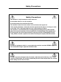
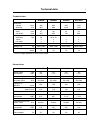
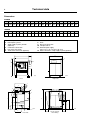
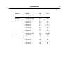
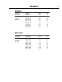
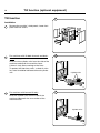
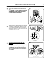
Installation manual Washer extractors W4400H, W4600H, W4850H, W41100H Type W4.H. Clarus Control Installation manual in original language 438 9211-81/EN 2011.01.31 Contents Contents Safety Precautions......................................................................................5 Technical data.............................................................................................7 Installation.................................................................................................11 Location and surface............................................................................11 Mechanical installation.........................................................................11 Machine equipped with weight measurement.....................................11 Connecting the water supply...............................................................16 Steam supply........................................................................................17 Compressed air connection.................................................................18 Drain.....................................................................................................20 Ventilation.............................................................................................20 Detergent dispenser, non-liquid detergents.........................................21 Installation of equipment for external liquid supply..............................21 Electrical installation.............................................................................22 Tilt function (optional equipment) ............................................................26 The manufacturer reserves the right to make changes to design and component specifications. 3 Safety Precautions Safety Precautions The machine is only intended for water-wash use. Do not allow minors to use the machine. Do not hose down the machine with water. The machine's door lock must under no circumstances be bypassed. If the machine develops a fault, this must be reported to the person in charge as soon as possible. This is important both for your safety and that of others. The machine is not intended to be used by people (including minors) with reduced physical or mental capacity or lack of experience and knowledge. Such people must be instructed in the use of the machine by a person who has responsibility for their safety. Minors must be supervised to ensure that they do not play with the machine. All external equipment which is connected to the machine must be CE/EMC-approved and connected using an approved shielded cable. In order to prevent damage to the electronics (and other parts) that may occur as the result of condensation, the machine should be placed in room temperature for 24 hours before being used for the first time. 5 Technical data 7 Technical data W4400H W4600H W4850H W41100H Innerdrum volume diameter litres mm 400 920 600 980 850 1220 1100 1220 Drum speed wash extraction rpm rpm 37 825 36 800 42 720 42 663 Heating electricity kW steam hot water 36 x x 36 or 54 x x – x x – x x G-factor 350 350 350 300 1380-1480 2200-2300* 2300-2400* 76 73 73 W4400H W4600H W4850H W41100H Weight, net kg 1095-1450* Sound pressure level dB (A) 75 * Precise weight depends on accessories fitted. Connections Water valves connection DN BSP 32 1 1/4" 32 1 1/4" 40 1 1/2" 40 1 1/2" Rec. water pressure kPa 200-600 200-600 200-600 200-600 Functioning limits for water valve kPa 50-1000 50-1000 50-1000 50-1000 Capacity at 300 kPa l/min 150 150 200 200 Drain valve outer Ø mm 110 110 110 110 Draining capacity l/min 400 400 400 400 Steam valve connection DN BSP 20 3/4" 20 3/4" 32 1 1/4" 32 1 1/4" Rec. steam pressure kPa 300-600 300-600 300-600 300-600 Functioning limits for steam valve kPa 50-800 50-800 50-800 50-800 Compressed air connection DN BSP 6 1/8" 6 1/8" 6 1/8" 6 1/8" Rec. air pressure kPa 500-700 500-700 500-700 500-700 l/h 20 20 20 20 Consumption Technical data 8 Dimensions W4400H A B C D E F G H I K L M N O P R S T U V 13251450 2015 910 300 1865 270 660 525 425 895 1425 420 435 220511402235 950 345 370 W4600H A B C D E F G H I K L M N O P R S T U V 13901585 2015 910 300 1865 270 660 525 425 960 1425 420 435 220011202225 935 300 325 1 2 3 4 5 6 7 8 9 10 11 12 Control panel Door opening ø 535 Soap supply injector, powder (optional) Cold water connection Hot water connection Third water connection (optional) A Steam connection Drain Electrical connection Compressed air External liquid supply, 6 pcs ø 10, 1 pc ø 16 and 1 pc ø 20 Water connection, soap supply injector (optional) E B 9 1 3 2 C D 6695 6696 A Right side Front L 4 5 6 H I 12 K 9 11 10 7 F P S G M T R N 6697 A O 6698 8 Rear side U The movement when tilting V Technical data 9 Dimensions W4850H A B C D E F G H I K L M N O P R S T U V 16401635 2230 995 380 21351070 830 635 445 11401660 435 820 241011752480 960 285 400 W41100H A B C D E F G H I K L M N O P R S T U V 16401850 2230 995 380 21351070 830 635 445 11401660 435 820 240011602480 955 240 335 1 2 3 4 5 6 7 8 9 10 11 12 Control panel Door opening ø 700 mm / 27 9/16" Soap supply injector, powder (optional) Cold water connection Hot water connection Third water connection (optional) A Steam connection Drain Electrical connection Compressed air External liquid supply, 6 pcs ø 10 mm / 3/8", 1 pc ø 16 mm / 5/8" and 1 pc ø 20 mm / 13/16" Water connection, soap supply injector (optional) E B 9 1 3 2 C D 6695 6696 B Right side Front L 4 G I 12 5 6 H 7 K 9 11 10 F P S M T R N 6697 B O 6698 8 Rear side U The movement when tilting V Technical data 10 Technical data W4400H W4600H W4850H W41100H Frequency of the dynamic force Hz 13.8 12.7 12.0 11.1 Max floor load at extraction kN 15.8 ± 1.2 15.9 ± 6.4 22 ± 7.3 24 ± 7.3 Sound levels Airborne sound level dB (A) re 2x10⁻⁵ Pa 75 76 73 73 With insulation < 70 < 70 < 70 < 70 5.5 6 6.7 6.8 Motor Power consumption kW Installation Installation For the installation of machines with optional equipment (such as the tilt function), see also the section ”Optional equipment” at the end of this manual. 11 1 1000 mm 500 mm The washer extractor is supplied bolted in place on a pallet and packaged in a delivery crate. In some cases the machine may be supplied in waterproof/dustproof packaging. The direction from which the machine must be lifted and the machine centre of gravity are shown on the packaging. 5541 Location and surface The machine must not be sited over an open floor drain. Check that the floor has an even surface and is level. The floor must be capable of withstanding the following: See "Technical data". 2 The following clearances are recommended: 1 • at least 1000 mm between the machine and any wall behind it. • at least 500 mm at each side, between the side of the machine and a wall, or between machines where these are side by side. Mechanical installation 2 3 • Remove the packaging material. Remove the machine’s rear cover, side panels and lower front panel. • Remove the eight bolts securing the machine’s outer- and innerframe onto the pallet. 5542 3 Machine equipped with weight measurement The load cells, which are fitted by the machine’s feet, are sensitive to knocks and impacts. 5543 12 4 5 Installation • Use a fork-lift truck to lift the machine. 4 • Position the four blocks of wood supplied, one beneath each machine foot (on the outer frame), within the recesses in the pallet. 5545 5 7222 Installation 6 7 8 • Lower the machine (A) and withdraw the truck forks (B). The machine should now be standing on the four blocks, and the pallet will be on the floor, clear of the machine. The next step is to insert the truck forks very carefully between machine and pallet (C). 13 6 • Lift the machine and remove pallet and blocks. • The feet can be of two types: fixed feet or rotating feet if the machine is to be fitted with tilt or weighing function. For machines with tilt or weighing function: screw on the machine’s feet. • If the machine is to have the tilt function, this is a suitable time to install the corner posts which hold the protective plates, and also, where applicable, the position sensors (see the section ”Tilt function (optional equipment)”). 5547 7 • It is important that the wheels are installed with the wider side facing in towards the machine in order for the tilt protection to fit. 5548 8 7223 Installation 14 • Put the machine in place. Mark out and drill the holes for fixing the feet. Hole diameter: 15 mm. 9 9 5550, 6056 10 For standard machines A B C D E F G H W4400H W4600H W4850H 1325 1445 1160 190 50 1310 90 10 1390 1605 1315 190 50 1370 90 10 10 W41100H 1640 1635 1370 190 50 1610 90 15 1640 1850 1585 190 50 1610 90 15 11 A D B C H E G For machines with tilt or weighing function A B C D E F G H K L M N O P W4400H W4600H W4850H 1325 1390 1445 1605 1170 1325 200 200 50 45 1340 1400 140 140 -10 -10 275 275 715 870 665 695 335 335 335 335 Tilting devices 1640 1635 1380 200 45 1640 140 0 270 925 820 335 335 F FRONT W41100H 1640 1850 1600 200 45 1640 140 0 270 1140 820 335 335 11 A D M P C L N O E W00258 P B K G FRONT H F 5868A Installation 15 12 12 13 14 Use a spirit level and, where necessary, the ”washers” (or rectangular metal plates) supplied, to ensure that the floor mountings are level. • Put the machine in place. Use a spirit level on suitable surfaces of the outer frame to check that the machine is level. Check too that the machine is resting firmly on all four feet. • Bolt the machine feet to the floor. Then check again that the machine is resting firmly (without movement) and is level. 3742 13 5551 14 5552 Installation 16 Connecting the water supply 15 The supply pipes to the machine should be fitted with manual shut-off valves to facilitate installation and service. Fit filters to the manual shut-off valves. Refer to local utilities regulations when fitting non-return valves. 15 A B C The hoses should be rated for high pressure and for 2.5 MPa. The following values apply to water pressure: • recommended: 300-600 kPa • limiting values, min: 50 kPa max: 1 MPa The hoses should be flushed through before being connected to the machine. The hoses should hang in gradual arcs. This is particularly important if the machine is fitted with a tilting function. Connections with pipes directly to the machine are not allowed. Connect the hoses as follows: • cold water to (A) • hot water to (B) • (if using a third water supply:) the third water hose to (C). W4400H, W4600H Sizes of A, B and C: DN 25 (1" BSP). W4850H, W41100H Sizes of A, B and C: DN 32 (1 1/4" BSP). 5869 Installation Steam supply 16 The supply hose (A) must have a manual shut-off valve to make installation and servicing easier. Fit filter to the manual shut-off valve. Connections with pipes directly to the machine are not allowed. 17 16 A Connect an approved hose between filter and machine. The following values apply to steam pressure: • recommended: 300-600 kPa • limiting values, min: 50 kPa max: 800 kPa The hose should hang in a gradual arc. This is particularly important if the machine is fitted with a tilting function. W4400H, W4600H 4138 W4400H, W4600H Connection size: DN 20 (3/4" BSP). W4850H, W41100H Connection size: DN 32 (1 1/4" BSP). A W4850H, W41100H 5870 Installation 18 Compressed air connection 17 18 19 17 A pressure regulator complete with water separation device is to be installed on the machine. When the machine is supplied, the angled coupling (1), hose (2) and bracket (3) for the pressure regulator will already be installed. 3 Install the quick-connector for the hose and a bushing (for the hose from the compressed air supply) on the pressure regulator. 2 Install the regulator on the bracket using two screws. Connect the compressed air hose using the quick-connector. Screw on the pressure gauge (1). 1 5873 18 Bushing Quick connector 3968 19 1 5874 Installation 20 Connect the hose from the compressed air supply to the bushing on the pressure regulator. Connect the hose so it hangs in a gentle arc. This is particularly important if the machine has the tilt function. 19 20 A The connecting hose must be rated for a pressure of at least 1 MPa. The following values apply to the compressed air supply: • Recommended pressure: 500-700 kPa 5871 Installation 20 Drain 21 21 The connector for the machine discharge (A) has an external diameter of 110 mm. The distance between the machine and the floor gully or drainage channel should be at least 250 mm. Connect a hose or a pipe to the drain connection. Avoid acute angles or kinks which could impede the flow. The hose or pipe should open into a floor gully, drainage channel or similar waste outlet. Make sure that the hose’s function is unaffected by the tilting function if the machine has this feature. 250 mm B A C If the machine has a second discharge, B and C must also be connected to the floor drain. Ventilation 22 The vent (A) from the washing machine drum is at the back of the machine. If bleach or other additives are used, the pipe should be extended and connected to a ventilation system. 5577 22 A 5572 Installation Detergent dispenser, non-liquid detergents 21 23 If only non-liquid detergents are to be used in the detergent dispenser, the following adaptation is recommended: 23 Drill two 5 mm holes in the bottom of each scoop to allow any water left to drain off. Installation of equipment for external liquid supply Electrical installation may only be carried out by competent, authorised personnel. 0355 All external equipment which is connected to the machine must be CE/EMC-approved. 24 25 24 The machine is fitted with 8 connections as standard , A (6 x ø10, 1 x ø16 and 1 x ø20), which are intended for connecting hoses from an external dispensing system. The external dosage unit connects to the X146 via the upper terminal in the coin operation unit. There are a total of 8 outlets for the dosing of washing detergent. The number on the terminal corresponds to the numbering of the liquid detergent function when setting the wash programme. A common zero for all the outlets can be found on the X146 terminal ”Neutral”. 230 V max 0.5 A only intended for control voltage. If the machine is not fitted with a detergent reservoir, then additional signals can be received from X140. A 5875 25 6527 Installation 22 Electrical installation 26 Electrical installation may only be carried out by competent, authorised personnel. Check that the earth conductor is correctly connected. The electrical cable for the machine's power supply should hang in a gentle arc. This is particularly important if the machine is equipped with the tilt function or weighing equipment. 26 Connect the machine to a separate mains circuit with its own circuit breaker(s). The various ratings required for circuit breakers are shown in the table. Connect the cable to the main switch inside the compartment on the machine rear, see illustration. The electrical cable used must be of a suitable size/rating. For the correct size/rating for this cable, check the relevant local or national regulations. If an earth leakage circuit breaker (or RCD - residual current device) is used, it must be installed to protect the washer extractor only. 6585 Installation Heating Voltage alternative alternative heating 200 V 3 AC No or Steam 208-240 V 3 AC 230/400 V 3 AC heating 240 V 3 AC 346 V 3 AC 380 V 3 AC 400 V 3 AC 415 V 3 AC 440 V 3 AC 480 V 3 AC 230/400 V 3 AC Electrical heated 240 V 3 AC 346 V 3 AC 380 V 3 AC 400 V 3 AC 415 V 3 AC 440 V 3 AC 480 V 3 AC 23 Total kW 5,5 5,5 5,5 5,5 5,5 5,5 5,5 5,5 5,5 5,5 Fuse A 25 25 25/16 25 16 16 16 16 16 16 38 38 38 38 38 38 38 38 100/63 100 80 63 63 63 63 50 Installation 24 W4600H Heating alternative Voltage alternative heating 200 V 3 AC No or Steam 230 V 3 AC 230 V 3 AC heating 240 V 3 AC 240 V 3 AC 380 V 3 AC 400 V 3 AC 415 V 3 AC 440 V 3 AC 480 V 3 AC 230 V 3 AC Electrical heated 230 V 3 AC 240 V 3 AC 240 V 3 AC 380 V 3 AC 380 V 3 AC 400 V 3 AC 400 V 3 AC 415 V 3 AC 415 V 3 AC 440 V 3 AC 440 V 3 AC 480 V 3 AC Total kW Fuse A 4,0 4,0 4,0 4,0 4,0 4,0 4,0 4,0 4,0 4,0 20 16 16 16 16 16 16 16 16 16 38 56 38 56 38 56 38 56 38 56 38 56 56 100 160 100 160 63 100 63 100 63 100 63 80 80 Installation 25 W4850H Heating alternative Voltage alternative heating 200 V 3 AC No Steam 230 V 3 AC or 240 V 3 AC heating 380 V 3 AC 400 V 3 AC 415 V 3 AC 440 V 3 AC 480 V 3 AC Total kW Fuse A 6,7 6,7 6,7 6,7 6,7 6,7 6,7 6,7 35 25 20 16 16 16 16 16 Total kW Fuse A 5,3 5,3 5,3 5,3 5,3 5,3 5,3 5,3 35 25 20 16 16 16 16 16 W41100H Heating alternative Voltage alternative heating 200 V 3 AC No Steam 230 V 3 AC or heating 240 V 3 AC 380 V 3 AC 400 V 3 AC 415 V 3 AC 440 V 3 AC 480 V 3 AC Tilt function (optional equipment) 26 Tilt function 1 Installation 1 Remove the machine’s side panels, lower front panel and rear covers. 3449 2 For machines with tilt both forwards and backwards: 2 Insert the two cylinder units from the side of the machine underneath the machine frame. If there is vinyl floor-covering on the floor: To protect the floor from wear, a sheet of stainless steel should be laid beneath each cylinder unit. Cylinder units 6044 3 For machines with forward tilt only: 3 Insert the cylinder unit from the side of the machine underneath the rear section of the machine frame. Cylinder units 6045 Tilt function (optional equipment) 4 Secure the cylinder units using four bolts and nuts. 27 4 It is important to fit four washers (each 5 mm thick) between each cylinder unit and the machine frame (see illustration). 4 washers 4 washers 3453 5 Fit the four corner posts, one for each corner of the machine, using the bolts which secure the machine feet to the floor. Adjust the clearance between the upper part of each corner post and the machine so it is 14 mm. 5 14 mm 3553 6 For machines with tilt both forwards and backwards: 6 Fit two pneumatic position sensors on two of the machine feet: at left-hand front and right-hand rear, diagonally opposed. The position sensors are to be fitted using the inner two fastening bolts of the feet, mounted on the corner posts just installed. Position sensors 6046 Tilt function (optional equipment) 28 For machines with tilt both forwards and backwards: 7 The compressed air lines which are to be connected to the air bellows and position sensors are supplied bundled on the machine rear. Connect the lines to the air bellows and pressure sensors according to the table below. These lines do not need to be fastened to the frame, but can be laid on the floor underneath the machine. 2 1 The air lines are marked as follows: 7 ID marking Connect to 1 Rear air bellows 2 Front air bellows 3 Rear pressure sensor, connection 1 4 Rear pressure sensor, connection 2 5 Front pressure sensor, connection 1 6 Front pressure sensor, connection 2 8 6047 Note that the tubes for the pressure sensors must be connected correctly, see Fig. 7. 3 6 –Connection 1 – same side as data plate. –Connection 2 – same side as the inset white plate. 4 6048 5 8 6026 Tilt function (optional equipment) 9 For machines with forward tilt only: 29 9 The compressed air line to be connected to the air bellows is supplied bundled on the machine rear. Connect this line to the connection nipple on the top of the bellows. 6049 30 10 Tilt function (optional equipment) Test the tilt function: 10 • Switch on the machine electrical switch(es) and turn on the compressed air supply. • Open the door and lock it open. • The uppermost switch on the tilt control unit tilts the machine either backwards (turn switch anticlockwise) or forwards (turn switch clockwise). The middle switch returns the machine to its normal (upright) position. These switches must be kept actuated throughout the entire tilt movement. If the switch is released, the tilt movement will halt and the machine will stop in its position. • The bottom switch on the control unit rotates the drum either clockwise or anticlockwise. • Check that the machine cannot tilt in the opposite direction until it has returned to its normal position after an earlier tilt. 6025 11 • Check for any possible leaks from compressed air lines or from bellows and sensors. Refit the machine panels/covers. 11 Fit two nut clips to each corner post. The nut clips slot into the rear grooves on the posts. Nut clip 3484 12 Fit the rubber dampers and sleeves to the front end of each side panel strip. 12 Rubber damper Sleeve Washer Screw Nut 3485 Tilt function (optional equipment) 13 Position and fasten the side panel strips. 31 13 3486 14 Fit the two counterweights to the front panel strip. The bolt heads should be at the bottom. 14 Counterweights 3487 15 Hang the front panel strip on the two sleeves you fitted to the side strips. Protective plates are mounted on the front and rear. 15 Sleeve 3488 Electrolux Laundry Systems Sweden AB 341 80 Ljungby, Sweden www.electrolux.com/laundrysystems Share more of our thinking at www.electrolux.com