1
User’s Manual
– Version: 2.33 –
Table of Contents
TABLE OF CONTENTS
2
PREFACES
5
0.1 ABOUT THIS MANUAL
5
0.2 COPYRIGHT DECLARATIONS
5
0.3 TRADEMARKS
5
0.4 SAFETY INSTRUCTIONS
5
0.5 WARRANTY
5
INTRODUCE
6
1.1 OVERVIEW
6
1.2 ACRONYMS TABLE
6
1.3 INTRODUCTION
7
1.4 FRONT PANEL LED INDICATORS & REAR PANELS
1.4.1 VOIP GATEWAY & SIP PROXY SERVER & GATEKEEPER OUTLOOK
1.4.2 FRONT PANEL LED AND CONTAINER DESCRIPTIONS
1.4.3 REAR PANEL DESCRIPTIONS
8
8
9
12
1.5 FEATURES AND SPECIFICATIONS
1.5.1 VOIP GATEWAY FEATURES
1.5.2 H.323 GATEKEEPER FEATURES – EMBEDDED SOFTWARE
1.5.3 SIP PROXY SERVER FEATURES – EMBEDDED SOFTWARE
1.5.4 VOIP GATEWAY & EMBEDDED H.323 GATEKEEPER & SIP PROXY SERVER SPECIFICATIONS
16
16
17
17
17
INSTALLATION AND SETUP
19
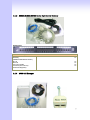
2.1 PACKAGE CONTENT
19
2.1.1 L200/S200/S400 SERIES GATEWAY & EMBEDDED H.323 GATEKEEPER/ SIP PROXY SERVER20
2.1.2 S800 SERIES GATEWAY & EMBEDDED H.323 GATEKEEPER/ SIP PROXY SERVER
20
2.1.3 SB800/S1600/S2400 SERIES HIGH DENSITY GATEWAY
21
2.1.4 Call manager
21
2.2 INSTALLATION
22
2.3 SETUP
2.3.1 FACTORY DEFAULT SETTING
2.3.2 CONSOLE
2.3.3 TELNET
2.3.4 WEB USER INTERFACE
24
24
24
25
28
2
WIZARD FOR QUICK SETUP
32
3.1 WAN PORT TYPE SETUP
32
3.2 CONFIGURING NAT OR BRIDGE SETTING:
34
3.3 VOIP CALL PROTOCOL SETUP
35
GATEWAY SETTING
36
4.1 NETWORK CONFIGURATION
4.1.1 WAN PORT T YPE SETUP
4.1.2 CONFIGURING LAN IP ADDRESS AND DHCP SERVER
4.1.3 VIRTUAL SERVER SETUP
4.1.4 DYNAMIC DNS
4.1.5 NETWORK MANAGEMENT
38
38
40
41
41
42
4.2 VOIP SETUP
4.2.1 H.323 SETUP
4.2.2 SIP SETUP
4.2.3 DIRECT CALL (PEER TO PEER) SETUP
4.2.4 OTHER VOIP SETTING
43
43
51
57
60
4.3 SIP PROXY SERVER (SVR) SETUP
62
4.4 H.323 GATEKEEPER (GK) SETUP
67
4.5 CALL MANAGER SETUP
70
4.6 SYSTEM ADMINISTRATOR
4.6.1 SAVE CONFIGURATION AND REBOOT
4.6.2 ACCESS CONTROL
4.6.3 SET TO DEFAULT CONFIGURATION
4.6.4 BACKUP/RESTORE CONFIGURATION TO A FILE
4.6.5 SYSTEM INFORMATION DISPLAY FUNCTION
4.6.6 SNTP SETTING FUNCTION
4.6.7 CAPTURE PACKETS FUNCTION
71
71
71
72
72
73
73
74
4.7 UPDATE FIRMWARE(FOR GATEWAY & GK & SVR)
75
APPENDIX
78
A FAQ LIST
78
B SIP SETTING VOIPBUSTER
80
C ANSWER SUPERVISION
82
D SIP SPEEDS CALL
84
E INTEROPERABILITY LIST
86
F RJ21 (TELCO 50) CABLE AND PATCH PANEL INSTALL
87
G SB800 / S1600 / S2400 SERIES MODULE EXTENSION INSTALL
88
H GATEWAY VALUE SETTING
92
I SCENARIO APPLICATION SAMPLES
93
3
J FXO ANSWER MODE
96
4
PREFACES
0.1 About This Manual
This manual is designed to assist users in using VoIP Gateway and Call Manager. Information
in this document has been carefully checked for accuracy; however, no guarantee is given as to
the correctness of the contents. The information contained in this document is subject to change
without notice.
0.2 Copyright Declarations
Copyright 2006 Telephony Corporation. All rights reserved. This publication contains
information that is protected by copyright. No part may be reproduced, transmitted, transcribed,
stored in a retrieval system, or translated into any language without written permission from the
copyright holders.
0.3 Trademarks
Products and Corporate names appearing in this manual may or not be registered trade
marks or copyrights of their respective companies, and are used only for identification or
explanation and to the owners’ benefit, without to infringe.
0.4 Safety Instructions
The most careful attention has been devoted to quality standards in the manufacture of the
Gateway. Safety is a major factor in the design of every set. But, safety is your responsibility too.
Use only the required power voltage. Power Input: AC 100-240V, 50-60Hz
To reduce the risk of electric shock, do not disassemble this product. Opening
or removing covers may expose the Gateway to hazardous voltages. Incorrect
reassembly can cause electric shock when this product is subsequently used.
Never push objects of any kind into the equipment through housing slots since
they may touch hazardous voltage points or short out parts those could result
in a risk of electric shock. Never spill liquid of any kind on the product. If liquid
is spilled, please refer to the proper service personnel.
Use only Unshielded Twisted Pair (UTP) Category 5 Ethernet cable to RJ-45
port of the Gateway.
0.5 Warranty
We warrant to the original end user (purchaser) that the S series gateways will be free from any
defects in workmanship or materials for a period of one (1) years from the date of purchase from
the dealer. Please keep your purchase receipt in a safe place as it serves as proof of date of
purchase. During the warranty period, and upon proof of purchase, should the product have
indications of failure due to faulty workmanship and/or materials, we will, at our discretion, repair
or replace the defective products or components, without charge for either parts or labor, to
whatever extent we deem necessary to re-store the product to proper operating condition. Any
replacement will consist of a new or re-manufactured functionally equivalent product of equal
value, and will be offered solely at our discretion. This warranty will not apply if the product is
modified, misused, tampered with, damaged by an act of God, or subjected to abnormal working
conditions. The warranty does not cover the bundled or licensed software of other vendors.
Defects which do not significantly affect the usability of the product will not be covered by the
5
warranty. We reserve the right to revise the manual and online documentation and to make
changes from time to time in the contents hereof without obligation to notify any person of such
revision or changes.
Note
Repair or replacement, as provided under this warranty, is the exclusive remedy of the
purchaser. This warranty is in lieu of all other warranties, express or implied, including any
implied warranty of merchantability or fitness for a particular use or purpose. We shall in no
event be held liable for indirect or consequential damages of any kind of character to the
purchaser.
To obtain the services of this warranty, contact us for your Return Material Authorization
number (RMA). Products must be returned Postage Prepaid. It is recommended that the unit
be insured when shipped. Any returned products without proof of purchase or those with an
out-dated warranty will be repaired or replaced and the customer will be billed for parts and
labor. All repaired or replaced products will be shipped by us to the corresponding return
address, Postage Paid. This warranty gives you specific legal rights, and you may also have
other rights that vary from country to country.
Introduce
L / S series VoIP Gateway and Call Manager are the low to high VoIP total Solutions. This
document describes the usage of Voice gateway and Call Manager.
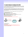
1.1 Overview
VoIP Gateway which is a device that allows one to connect a normal PSTN telephone to the
Internet in order to make or place telephone calls.
VoIP Gateway device may work in conjunction with a computer, such as an IP-sharing /
Router, or it may be a stand-alone device that communicates with a service provider over the
Internet.
VoIP Gateway provides a direct analog interface for computer modems, fax machines, analog
telephones, and other devices that require an analog port.
2/4/8 port Series VoIP Gateway can build in a simple H.323 Gatekeeper or SIP Proxy Server.
VoIP Gateway also support standard Internet services, such as IP-Sharing, NAT, Virtual
Server, DDNS, QOS, Port Filter, IP Filter function.
1.2 Acronyms Table
Acronym:
ADC
DAC
DDNS
Full Name:
Analog to Digital Converter
Digital to Analog Converter
Dynamic Domain Name System
Acronym:
CODEC
DC
DHCP
DMZ
DTMF
FXS
IP
L2TP
WAN
MII
NTP
RTP
Demilitarized Zone
Dual Tone Multi Frequency
Foreign Exchange Station
Internet Protocol
The Layer 2 Tunnel Protocol
Wide Area Network
Media Independent Interface
Network Time Protocol
Real-Time Transport Protocol
DNS
FXO
GMT
IPsec
LAN
MAC
NAT
PPTP
RTCP
Full Name:
Coder / Decoder
Direct Current
Dynamic Host Configuration
Protocol
Domain Name System
Foreign Exchange Office
Greenwich Mean Time
Internet Protocol Security
Local Area Network
Media Access Control
Network Address Translation
Point-to-Point Tunneling Protocol
Real-Time Transport Control
Protocol (also known as RTP
6
control protocol)
SIP
STUN
TCP
UPnP
Session Initiation Protocol
Simple Traversal of UDP through
NATs
Transmission Control Protocol
Universal Plug and Play
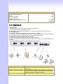
1.3 Introduction
SLIC
URI
Subscriber Line Interface Circuit
Uniform Resource Identifier
UDP
VoIP
User Datagram Protocol
Voice Over Internet Protocol
This VoIP Gateway provides a total solution for integrating voice-data network and PSTN.
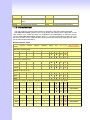
The L200 and S series gateway is low to high density port gateway which support SIP / H.323
VoIP Protocol. Low model (2/4 port) can embedded H.323 Gatekeeper or SIP Proxy Server
(Option). The L200 and S series gateway allows 2 ~ 24 lines (model option) analog voice and
fax communication over a traditional data communications/data networking digital Internet. There
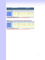
are 6 model compare table follow.
Model Compare Table
FXO Port
FXS Port
LAN Port
WAN Port
Model
LCD
RS-232
Display
port
SIP
H.323
H.323 Gatekeeper
/ SIP proxy Server
(Software embedded)
S2400 Series ( 24 analog lines)
S2400
0
24
1
1
√
√
√
√
S2412
12
12
1
1
√
√
√
√
S2424
24
0
1
1
√
√
√
√
S1600 Series ( 16 analog lines )
S1600
0
16
1
1
√
√
√
√
S1608
8
8
1
1
√
√
√
√
S1616
16
0
1
1
√
√
√
√
SB800 Series ( 8 analog lines )
SB 800
SB 804
SB 808
0
8
1
1
√
√
√
√
4
4
1
1
√
√
√
√
8
0
1
1
√
√
√
√
S800 Series( 8 analog lines Gateways /Embedded H.323 Gatekeepers/Embedded Sip Proxy Serves)
S800
0
8
1
1
√
√
√
SK800/SVR800
S802
2
6
1
1
√
√
√
SK802/SVR802
S804
4
4
1
1
√
√
√
SK804/SVR804
S808
8
0
1
1
√
√
√
SK808/SVR808
S400 Series ( 4 analog lines Gateways/embedded Gatekeepers/Sip Proxy Servers)
S400
0
4
4
1
√
√
SK400/SVR400
S401
1
3
4
1
√
√
SK401/SVR401
S402
2
2
4
1
√
√
SK402/SVR402
S404
4
0
4
1
√
√
SK404/SVR404
7
S200 Series ( 2 analog lines gateways/ Embedded H.323 Gatekeepers/ Embedded Sip Proxy Servers)
S200
0
2
4
1
√
√
SK200/SVR200
S201
1
1
4
1
√
√
SK201/SVR201
S202
2
0
4
1
√
√
SK202/SVR202
L200 Series ( 2 analog lines Gateways/embedded Gatekeepers/Sip Proxy Servers)
L200
0
2
1
1
√
√
LK200/LVR200
L201
1
1
1
1
√
√
LK201/LVR201
L202(*)
2
0
1
1
√
√
LK202/LVR202(*)
4
0
4
1
√
√
Call Manager
C400
* : manufacture by order (lead time : 60 days)
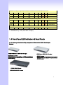
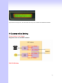
1.4 Front Panel LED Indicators & Rear Panels
1.4.1 Gateway & Embedded Sip proxy server & Embedded H.323 Gatekeeper
Outlook
S200/S400 Series & C400 Call Manager:
-S200/S400 VoIP Gateway
-SK200 /SK400 VoIP Gateway building in H.323 Gatekeeper Software
-SVR200/SVR400 VoIP Gateway building in SIP Proxy Server Software
-C400 Call Manager
S800 Series & C800 Call Manager:
-S800 VoIP Gateway
-SK800 VoIP Gateway building H.323 Gatekeeper Software
-SVR800 VoIP Gateway building SIP Proxy Server Software
-C800 Call Manager
S1600 / S2400 Series:
SSB800/S1600/S400 VoIP Gateway
-
8
L200 Series:
-L200 Series Gateway
-LK200 Series Gateway building in H.323 Gatekeeper Software
-LVR200 Series Gateway building in SIP Proxy Server Software
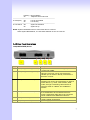
1.4.2 Front Panel LED and Container Descriptions
L200(GW/GK/SVR) Series
-----------------------------------------------------------------------------------LED
State
Description
-----------------------------------------------------------------------------------1. POWER
On
ATA is power ON
Off
ATA is power Off
------------------------------------------------------------------------------------2. WAN port
On
ATA network connection established
Flashing Data traffic on cable network
Off
Waiting for network connection
------------------------------------------------------------------------------------3. LAN port
On
LAN is connected successfully
Flashing Data is transmitting
Off
Ethernet not connected to PC
------------------------------------------------------------------------------------4. FXS
Off
Telephone Set is On-Hook
Flashing Ring Indication
On
Telephone Set is Off-Hook
------------------------------------------------------------------------------------5. FXO
Off
Line is On-hook
On
Line is In-Use
-------------------------------------------------------------------------------------
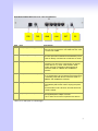
S200/S400(GW/GK/SVR) Series & C400 Call Manager
9
-----------------------------------------------------------------------------------LED
State
Description
-----------------------------------------------------------------------------------1. POWER
On
GW is power ON
Off
GW is power Off
------------------------------------------------------------------------------------2. WAN port
On
GW network connection established
Flashing Data traffic on cable network
Off
Waiting for network connection
------------------------------------------------------------------------------------3. LAN port
On
LAN is connected successfully
Flashing Data is transmitting
Off
Ethernet not connected to PC
------------------------------------------------------------------------------------4. FXS(Port)
Off
Telephone Set is On-Hook
Flashing Ring Indication
On
Telephone Set is Off-Hook
------------------------------------------------------------------------------------5. FXO(Port)
Off
Line is not enabled
On
Line is busy
NOTE: System initialization will turn some LEDs ON for a few sec.
When System Boot/Reboot , the Port LEDs will flash in turn for a few sec.
S800 (GW/GK/SVR) Series & C800 Call Manager
-----------------------------------------------------------------------------------------LED
State
Description
-----------------------------------------------------------------------------------------1. POWER
On
GW is power ON
Off
GW is power Off
-----------------------------------------------------------------------------------------2. RUN port
On
GW connection established
Flashing Data traffic on cable network
Off
Waiting for GW connection
-----------------------------------------------------------------------------------------3. WAN port
100M
On
GW network connection 100MB network
Off
GW network connection 10MB network
ACT
ON
GW network connection established
Flashing Data traffic on cable network
Off
Waiting for network connection
-----------------------------------------------------------------------------------------4. LAN port
100M
On
GW LAN connection 100MB network
Off
GW LAN connection 10MB network
10
ACT
On
LAN is connected successfully
Flashing Data is transmitting
Off
Ethernet not connected to PC
------------------------------------------------------------------------------------5. FXS(Port)
Off
Telephone Set is On-Hook
Flashing Ring Indication
On
Telephone Set is Off-Hook
------------------------------------------------------------------------------------6. FXO(Port)
Off
Line is not enabled
On
Line is busy
------------------------------------------------------------------------------------7. RES Button Push
Push Button until 5 second
Set to Factory Default
------------------------------------------------------------------------------------8. RS-232
Console port connect to PC
NOTE: System initialization will turn some LEDs ON for a few sec.
When System Boot/Reboot , the Port LEDs will flash in turn for a few sec.
SB800/S1600/S2400 Series Gateway
-----------------------------------------------------------------------------------------LED
State
Description
-----------------------------------------------------------------------------------------1. POWER
On
GW is power ON
Off
GW is power Off
-----------------------------------------------------------------------------------------2. RUN port
On
GW connection established
Flashing Data traffic on cable network
Off
Waiting for GW connection
-----------------------------------------------------------------------------------------3. WAN port
100M
On
GW network connection 100MB network
Off
GW network connection 10MB network
ACT
ON
GW network connection established
Flashing Data traffic on cable network
Off
Waiting for network connection
-----------------------------------------------------------------------------------------4. LAN port
100M
On
GW LAN connection 100MB network
Off
GW LAN connection 10MB network
ACT
On
LAN is connected successfully
Flashing Data is transmitting
Off
Ethernet not connected to PC
------------------------------------------------------------------------------------5. FXS(Port)
Off
Telephone Set is On-Hook
11
Flashing Ring Indication
On
Telephone Set is Off-Hook
------------------------------------------------------------------------------------6. FXO(Port)
Off
Line is not enabled
On
Line is busy
------------------------------------------------------------------------------------6. LCD Panel Off
System is Shutdown
On
System is Up
NOTE: System initialization will turn some LEDs ON for a few sec.
When System Boot/Reboot , the Port LEDs will flash in turn for a few sec.
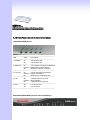
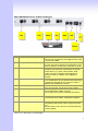
1.4.3 Rear Panel Descriptions
L200(GW/GK/SVR) Series
Item
1
Port
FXS(Foreign Exchange Station)
Description
FXS port can be connected to analog telephone sets
or Trunk Line of PBX.
Can be Connected to PBX or CO line with RJ-11
analog line. FXO port can be connected to the
extension port of a PBX or directly connected to a
PSTN line of carrier.
2
FXO(Foreign Exchange Office)
3
WAN(Wide Area Network)
Connect to the network with an Ethernet cable. This
port allows your ATA to be connected to an Internet
Access device, e.g. router, cable modem, ADSL
modem, through a networking cable with RJ-45
connectors used on 10BaseT and 100BaseTX
networks.
4
LAN(Local Area Network)
5
RES(Reset button)
6
AC power(DC in 12V)
Connect to PC with Ethernet cable. 1 port allows your
PC or Switch/Hub to be connected to the ATA
through a networking cable with RJ-45 connectors
used on 10BaseT and 100BaseTX networks.
Push this button until 3 seconds, and ATA will be set
to factory default configuration.
A power supply cable is inserted
12
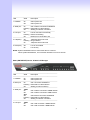
S200/S400(GW/GK/SVR) Series & C400 Call Manager
Item
1
Port
FXS(Foreign Exchange Station)
Description
Connect to Phone with RJ-11 (Black) analog line.
FXS port was connected to your telephone sets, FAX,
or Trunk Line of PBX.
2
FXO(Foreign Exchange Office)
Connect to PBX or CO line with RJ-11(Write) analog
line. FXO port was connected to the extension port of
a PBX or directly connected to a PSTN line of carrier.
3
WAN(Wide Area Network)
Connect to the network with an Ethernet cable. This
port allows your GW to be connected to an Internet
Access device, e.g. router, cable modem, ADSL
modem, through a networking cable with RJ-45
connectors used on 10BaseT and 100BaseTX
networks.
4
LAN(Local Area Network)
Connect to PC with Ethernet cable. 4 ports allow your
PC or Switch/Hub to be connected to the GW through
a networking cable with RJ-45 connectors used on
10BaseT and 100BaseTX networks.
5
RES(Reset button)
The reset button, when pressed, resets the cable
voice gateway without the need to unplug the power
cord.
Push this button until 5 seconds, and GW will be set
to factory default.
6
AC power(DC in 12V)
A power supply cable is inserted.
The supplied power adapter converts
110V or 220V AC to DC as required for this device.
*there is no FXO port in Call Manager
13
S800 (GW/GK/SVR) Series & C800 Call Manager
Item
1
Port
FXS(Foreign Exchange Station)
Description
Connect to Phone with RJ-11 (Black) analog line.
FXS port was connected to your telephone sets, FAX,
or Trunk Line of PBX.
Connect to PBX or CO line with RJ-11(Write) analog
line. FXO port was connected to the extension port of
a PBX or directly connected to a PSTN line of carrier.
Connect to the network with an Ethernet cable. This
port allows your GW to be connected to an Internet
Access device, e.g. router, cable modem, ADSL
modem, through a networking cable with RJ-45
connectors used on 10BaseT and 100BaseTX
networks.
Connect to PC with Ethernet cable. 1 port allow your
PC or Switch/Hub to be connected to the GW through
a networking cable with RJ-45 connectors used on
10BaseT and 100BaseTX networks.
Power Switch, turn on/off the GW power supplied. [I]
is turn on the power, and [o] is turn off the power.
A power supply cable is inserted.
The supplied power adapter converts
110V or 220V AC to DC as required for this device.
2
FXO(Foreign Exchange Office)
3
WAN(Wide Area Network)
4
LAN(Local Area Network)
5.
Switch power
6
AC power(DC in 12V)
7
RS-232
RS-232 console port connect to PC, Use Pc com port
to connect RS-232 console , setting GW configure.
8
RES(Reset button)
The reset button, when pressed, resets the cable
voice gateway without the need to unplug the power
cord.
Push this button until 5 seconds, and GW will be set
to factory default.
*there is no FXO port in Call Manager
14
SB800/S1600/S2400 Series Gateway
Item
1
Port
Standard Telco 50 PIN
Connector (RJ-21)
Description
It is a 50 pins RJ-21 connector for connecting to
telephone patch pane
2
RES(Reset button)
The reset button, when pressed, resets the cable
voice gateway without the need to unplug the power
cord.
Push this button until 5 seconds, and GW will be set
to factory default.
3
RS-232
RS-232 console port connect to PC, Use Pc com port
to connect RS-232 console , setting GW configure.
4
WAN(Wide Area Network)
5.
LAN(Local Area Network)
6
Switch power
7
AC power(DC in 12V)
Connect to the network with an Ethernet cable. This
port allows your GW to be connected to an Internet
Access device, e.g. router, cable modem, ADSL
modem, through a networking cable with RJ-45
connectors used on 10BaseT and 100BaseTX
networks.
Connect to PC with Ethernet cable. 1 port allow your
PC or Switch/Hub to be connected to the GW through
a networking cable with RJ-45 connectors used on
10BaseT and 100BaseTX networks.
Power Switch, turn on/off the GW power supplied. [I]
is turn on the power, and [o] is turn off the power.
A power supply cable is inserted.
The supplied power adapter converts
110V or 220V AC to DC as required for this device.
8
LCD Panel
Setting GW and view GW status, use [up/down]
button to select Menu, and [menu] button return to
main and click select.
15
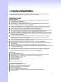
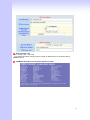
1.5 Features and Specifications
The L200 and S Series Gateways provide many built-in server and software features to
provide a convenient comprehensive solution for your VoIP network
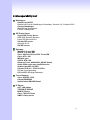
1.5.1 Gateway Features
VoIP Key Features
Both support SIP and H.323 protocols: SIP Registration and Digest Authentication and
H.323 Gatekeeper Registration.
Single Number / Account for multiple ports.
Caller ID Delivery and Detection: FXS support DTMF&FSK Caller ID generation; FXO
supports DTMF&FSK Caller ID detection. (Optional)
Smart VoIP call Dialing Book: VoIP call Book could provide any application VoIP call to any
type destination (Domain name / IP address, PSTN or PBX) or hunting number setting.
AC termination Impedance : 600/900 OHM and complex impedance
Answer Supervision for Polarity Reversal Detection and Voice detection
NAT traversal: This feature allow gateway to operate behind any NAT/Firewall device. There
is no need to change any configuration of NAT/Firewall like setting virtual server.
Smart-QoS: This feature provides good voice quality when user place a VoIP call and access
internet at the same time. The gateway will automatically start to reserve bandwidth for voice
traffic when VoIP call proceeds.
Call Hunting Facility: This function helps gateway to use the lines effectively. This facility
automatically transfers your incoming call to a free line. Subscribers need not indicate
numerous numbers of each port of gateway.
Voice channels status display: This function display each port status like as on-hook, off-hook,
calling number callee’s number, talk duration, codec.
Pulse Dial support: Support pulse dialing generation and detection. (Optional)
Flash Detection and Generation Program: FXO support Flash Generation and FXS support
Flash Detection.
CDR: Use Syslog Server to receive CDR information that gateway send by UDP.
Modules Card Extension: Extension FXO/FXO Modules card upgrade gateway port max to 24
port.(SB800/S1600/S2400)
Embedded H.323 Gatekeeper (GK) / SIP Proxy Server (SVR): For 2/4/8 port gateway can
embedded GK/SVR function. A simple H.323 GK / SIP proxy with gateway at the same
device. Support standard Registered and call Sever Function.(Option)
Call Features
Voice channels status display
Direct Dialing Mode : peer to peer call (support IP Address Call or Domain Name Call)
Register Call Mode : register to SIP Proxy Server or H.323 Gatekeeper
Adjustable volume : - 9 db ~ 9 db
Silence Compression(VAD)
Auto Dial for speed
Dynamic Jitter Buffer
Hot-Line Support(PLAR)
Configuration & Management
Web-based Graphical User Interface
RS232 for configuration(S800/S1600/S2400)
Remote management over the IP Network
FTP firmware upgrade
Backup and Restore Configuration file
Front LCD Panel for System Status and Management(SB800/S1600/S2400)
Syslog support
16
1.5.2 Embedded H.323 Gatekeeper Features
200 H.3232 endpoints scale: SK400 providing 250 H.323 endpoints to register.
Register Security Policy: SK400 providing security setting on your H.323 VoIP network. This
provides protection for VoIP calls and insures proper endpoint identification.
Pre-Granted Endpoints: letting other gateways or H.323 endpoints which were not register to
this embedded gatekeeper. And the registered VoIP Gateways can make an Off-Net call to
these pre-granted endpoints..
Real time Call Detail Record and Post Call Detail Record Report : Support Real Time CDR to
monitor VoIP calls, including caller ip, called ip , call date , call duration and other information.
Also providing a CDR report to look up VoIP call record.
Top 20 list: SK400 Gatekeeper can lists top 20 calls by call duration, caller number, calling
number, caller IP or callee IP address.
Syslog Client: Providing CDR information to Syslog Server.
1.5.3 Embedded Sip Proxy Features
200 SIP endpoints scale: SVR200 / SVR400 /SVR800 series providing 200 SIP endpoints to
register.
Trunk Line Setting for Off-Net Call: SVR400 / SVR 200 /SVR 800 series providing trunk
interface for Off-Net call by ITSP. (Optional)
Register Security Policy: SVR200 / SVR400 / SVR800 series providing MD5 authentication
setting.
Real time Call Detail Record and Post Call Detail Record Report : Support Real Time CDR to
monitor VoIP calls, including caller ip, called ip , call date , call duration and other information.
Also providing a CDR report to look up VoIP call record.
Top 20 list: SVR200 / SVR 400 / SVR800 series can lists top 20 calls by call duration, caller
number, calling number, caller IP or called IP address.
Syslog client: Send CDR information to Syslog server.
1.5.4 Gateway & Gatekeeper & Sip proxy server Specifications
S200/S400/S800 Series Gateway & Gatekeeper & Sip proxy server & Call Manager
Telephony Specification:
Voice Codec:
FAX support :
G.711(A-law /μ-law), G.729 AB,
G.723 (6.3 Kbps / 5.3Kbps).
T.30 / T.38.
Echo Cancellation:
G.165/G168(Version:2000).
FXO Caller ID detection :
DTMF and FSK (Optional).
FXO hang up detection / anti-seized :
FXO answer delay time:
Tone Learning Automatically / Manual Tone
Learning (Optional).
Support Battery Reverse Detection and Voice
Detection.
Support delay 0 – 8000 ms to answer.
Adjustable AC Termination Impedance :
600 / 900 OHM and complex Impedance.
Failsafe Mechanism (FXS relay to FXO) :
Power failed by pass support / Internet Failed by
pass (Optional)).
12K Hz and 16K Hz Metering (Customized)
Answer supervision:
Creative Metering:
IP Specification:
Protocol:
H.323 v2/v3/v4 and SIP (RFC 3261) ,
SDP (RFC 2327), Symmetric RTP,
17
STUN (RFC3489), ENUM (RFC 2916),
RTP Payload for DTMF Digits (RFC2833),
Outbound Proxy Support.
Support Virtual Server, DHCP Server.
LAN :
WAN:
Network Address Translation:
Support PPPoE client, DHCP client, Fix IP Address,
DDNS client.
Providing build-in NAT router function.
Smart QoS:
Guarantee the voice bandwidth
TOS:
IP TOS (IP Precedence) / DiffServ
General Specification
AC power :
AC100V-240V, DC12V/1.5A,50/60 Hz
Temperature:
0°C ~ 40°C (Operation)
Humidity:
up to 90% non-condensing
Emission:
FCC Part 15 Class B, CE Mark
Dimension :
IU-440 x 250 x 45 mm(SB800/S1600/S2400)
260 x 130 x 35 mm(S800/GK/SVR)
260 x 130 x 35 mm(S200/S400/GK/SVR)
5200 g(SB800/S1600/S2400)
1500g (Aluminum)(S800/GK/SVR)
00g (Aluminum )(S200/S400/GK/SVR)
Standard 50 pin RJ-21 Telco connectors
(SB800/S1600/S2400)
Weight:
Others:
SB800/S1600/S2400 Series gateway can be extension. Combination different modules
card, you can change/upgrade your gateway FXS/FXO ports. Max Up to 24 ports.
Modules Card Table (SB800/S1600/S2400 Only)
Mother Board
Description and Function
SB800
Mother Board with 8 FXS Interface
SB804
Mother Board with 4 FXS + 4 FXO Interface
SB808
Mother Board with 8 FXO Interface
Modules Card
Description and Function
SM800
8 FXS Interface Module
SM804
4 FXS + 4 FXO Interface Module
SM808
8 FXO Interface Module
18
Installation and Setup
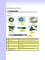
2.1 Package Content
Please check enclosed product and its accessories before installation. (Refer to the item
number). These contents are from pre-released product. The contents for the final product might
change a little bit.
Appurtenances:
Item
Appurtenances
Description
1
CD-ROM
CD Include in all product user manual and datasheet.
2
RJ-45 cable
Internet cable RJ-45 connect to NIC/Gateway/Router
3
RS-232 cable
RS - 232 Console port connect to PC COM port.
4
Power supply & cable(8)
5
Power cable(16/24)
Power Supply,input:100-240V output:+12V
(Europe/UK/US)
Power Supply cable.
6
Power supply & cable(2/4)
7
25 port Telephone
Patch Panel and Cable
(Optional).
Power Supply,input:100-240V output:+12V
(Europe/UK/US)
For 16/24 port telephone interface Patch Panel .
19
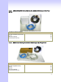
2.1.1 L200 /S200/S400 Series Gateway & embedded Gatekeeper/ Sip Proxy
Server
The 2/4 Port packet contents:
GW,GK,SVR(S200/ S400 Series)
RJ-45
AC Power Adapter
CD-Rom(User manual)
2.1.2
X1
X1
X1
X1
S800 Series Gateway & embedded Gatekeeper/ Sip Proxy Server
The 8 Port packet contents:
GW,GK,SVR(S800 Series)
RJ-45
RS-232
AC Power Adapter
CD-Rom(User manual)
X1
X1
X1
X1
X1
20
2.1.3
SB800/S1600/S2400 Series High Density Gateway
Patch Panel:
The 8/16/24 Port packet contents:
Gateway
(SB800/S1600/S2400 Series)
RJ-45
RS-232
AC Power Cable
CD-Rom(User manual)
Patch Panel(Option)
X1
X1
X1
X1
X1
2.1.4 C400 Call Manager
21
Call Manager contents:
Call Manager(C400/C800)
RJ-45
RS-232(only C800)
AC Power Adapter
CD-Rom(User manual)
Modular Duplex Jack Extension Cord
X1
X1
(X1)
X1
X1
X4 (C400)
X8 (C800)
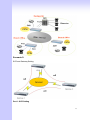
2.2 Installation
Install Gateway
1 Connect the 12V DC IN to the power outlet with power adaptor.
2 Connect FXO to PSTN / PBX Extension Line.
3 Connect FXS to a telephone jack with the RJ-11 analog cable (Phone / PBX Trunk Line.)
Connecting to a PC:
1 Connect the Ethernet cable (with RJ-45 connector) to any LAN port.
2 Connect the other end of the Ethernet cable to your PC’s installed network interface card (NIC).
3 The LED indicators at both the Ethernet port and the NIC should be ON.
Connecting to an External Ethernet Hub or Switch:
1 Connect the Ethernet cable (with RJ-45 connector) to WAN port.
2 Connect the other end of the Ethernet cable to DSL/Cable modem or the external Ethernet hub
or switch.
3 The LED indicators on both the LAN port and the external Switch.
Port
Description
FXS(Foreign Exchange Station)
FXS port can be connected to analog telephone sets or Trunk
Line of PBX.
Can be Connected to PBX or CO line with RJ-11 analog line.
FXO port can be connected to the extension port of a PBX or
directly connected to a PSTN line of carrier.
Connect to the network with an Ethernet cable. This port
FXO(Foreign Exchange Office)
WAN(Wide Area Network)
22
LAN(Local Area Network)
RES(Reset button)
AC power(DC in 12V)
allows your GW to be connected to an Internet Access
device, e.g. router, cable modem, ADSL modem, through a
networking cable with RJ-45 connectors used on 10BaseT
and 100BaseTX networks.
Connect to PC with Ethernet cable. 1 port allows your PC or
Switch/Hub to be connected to the GW through a networking
cable with RJ-45 connectors used on 10BaseT and
100BaseTX networks.
Push this button until 3 seconds, and GW will be set to
factory default configuration.
A power supply cable is inserted
Call Manager ONLY
Connect the cord to FXS port
Connect the PSTN line to PSTN port
Connect the PBX to phone port
The hardware installation is now complete. The following sections will guide you through setting
up your management PC and connecting to the Web User Interface.
23
2.3 Setup
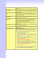
There are 3 way to setting gateway - [Web User Interface] [Telnet] [Console] (Some Series
modules have RS-232 console port like S800/SB800/S1600/S2400).
2.3.1 Factory Default setting
WAN Port IP address : 192.168.1.1
LAN Port IP address : 222.222.222.1
LAN DHCP Server enable IP range: 222.222.222.51 ~ 222.222.222.100
VoIP Number(S200 Series) Port_1~Port_2 number:100,200
VoIP Number(S400 Series) Port_1~Port_4 number:100,200,300,400
VoIP Number(S800 Series) Port_1~Port_8 number:100,200,300,400,500,600,700,800
VoIP Number(SB800 Series) Port_1 ~ Port 8 number : 101~ 108
VoIP Number(S1600 Series) Port_1 ~ Port 16 number: 101~ 116
VoIP Number(S2400 Series) Port_1 ~ Port 24 number: 101~ 124
VoIP default setting was H.323 signal protocol, Direct Mode, Fast-Start and G.723 codec.
Default login authentication username : admin, password : admin
2.3.2 Console
RS-232 port (DB-9pin male connector), Configure the COM Port Properties as following: Bits
per second: 9600, Flow control: None
1. Connect Gateway RS-232 port to PC COM Port.
2. Power on gateway.
3. Open Terminal Program (ie. Windows XP Hyper Terminal)
[Start] → [Program file] → [Accessories] → [communications] → [Hyper Terminal]
4. Create New connection. Select “Com” port that connect PC to gateway
24
5.
6.
7.
8.
Make connection(Bits Pre second:38400 Flow contact: None)
Input “Enter” and Show Welcome display.
Login, input the Password to login.(Password as the same as Access, default is admin)
Setting Gateway Configure like telnet mode
(Setting Table following as Telnet Setting table)
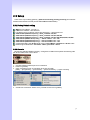
2.3.3 Telnet
Connect WAN/LAN port to Internet or PC and gateway at the same subnet. you can use telnet
remote to configure your gateway.
1. Connect Gateway online (Wan/Lan)
2. Remote Gateway by Telnet. If telnet successful, you will see Login display.
(For Example: telnet 222.222.222.1)
25
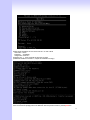
3. Input Password (Gateway Access password, Default: admin), If login successful, you will enter
the welcome display.
(1:Gateway Model 2:Firmware Version 3:Wan/Lan Status 4.DDNS Status 5:VoIP Status)
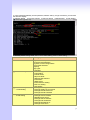
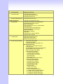
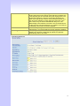
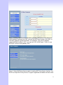
4. Gateway Telnet Setting Table, Use 1~9 a~z select setting, “ESC” is back setting.
Item
Setting Option
Main
[1]Advanced Setup
[1]Advanced Setup
……1.WAN Setting
[1]Advanced Setup
……2.LAN Setting
[1] Advanced Setup.
[2] System Administration.
[3] Save Current Configurations.
[4] Upgrade Software.
[5] Ping.
[6] Logout.
[7] Restart.
1.WAN Setting
2.LAN Setting
3.Virtual Server
4.Dynamic DNS
5.Network Management
6.VoIP Basic
7.Dialing Plan
8.VoIP Advance Setting
9.Hot Line Setting
a.Port Status
1.Change WAN Type to DHCP
2.Change WAN Type to Fixed IP
3.Change PPPoE Username
4.Change PPPoE Password
1.Change to Bridge Mode
2.Change LAN IP Address
3.Disable DHCP Server
4.Change Start IP Address
5.Change End IP Address
6.Change DNS Server IP
7.Change Lease Time
26
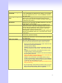
[1]Advanced Setup
……3.Virtual Server
[1]Advanced Setup
……4.Dynamic DNS
[1]Advanced Setup
……5.Network Management
[1]Advanced Setup
……6.VoIP Basic
[1]Advanced Setup
……7.Dialing Plan
[1]Advanced Setup
……8.VoIP Advance Setting
1.Add Virtual Server
2.Delete Virtual Server
1.Change DDNS username
2.Change DDNS password
3.Change DDNS domain name
4.Change DNS server IP
1.Change web server port
2.Change telnet server port
1.Change VoIP Protocol to H.323
2.Change Port Number/Account/Password
3.Enable/Disable Public account
4.SIP hunting setting
5.Change SIP Proxy Server IP Address/DNS
6.Use net2phone
7.Change Register Interval(seconds)
8.Enable/Disable SIP authentication
9.NAT Pass Method
a.STUN Server address
b.SIP realm
c.Outbound Proxy Server address
d.Change SIP Local Port
1.Add Outbound Direct Call
2.Delete Outbound Direct Call
3.Add Inbound Direct Call
4.Delete Inbound Direct Call
(1)Sip Advance
1.Set DTMF Relay Mode
2.Change FAX Mode
3.Change RFC2833 Payload(96-127)
(2)Telephone Advance
1.VAD(Silence Compression)On/Off
2.Change Codec
3.Enable/Disable UK PSTN Tone Detection?
4.Enable/Disable Dial Complete Tone
5.Dial Termination Key Setting
6.FXS Parameters Setting
1.Change FXS Impedance
2.Change Phone In Volume
3.Change Phone Out Volume
4.Flash Detection
5.Ring Frequency
6.FXS Battery reversal generation
7.FXO Parameters Setting
1.Change FXO Impedance
2.Change Line In Volume
3.Change Line Out Volume
4.Change FXO Tx Gain
5.Change FXO Rx Gain
6.Flash Duration
7 DTMF Tone Power
8.FXO Transmit Hybrid
9. Answer Supervision Setting
a. Change Ringer Voltage Threshold
b. Enable Line Silence Disconnect
c. Change FXO Answer delay time
d. FXO Ringer Voltage Filter Setting
27
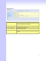
[1]Advanced Setup
……9.Hot Line Setting
[2] System Administration.
(3)Network Advance
1.Disable Smart QOS
2.Bandwidth Control
3.G.723 Bandwidth
4.G.729 Bandwidth
5.Set IP TOS
1.Change Port1 Hot Line Number
2.Change Port2 Hot Line Number…….(To your own port)
1.Save Configuration
2.Access Control
3.Set to Default
4.System Information
5.NTP Setting
6.Syslog Setting
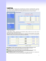
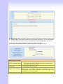
2.3.4 Web User Interface
The gateway has a built-in HTTP(Web) server for configuration. Before you use the gateway to
access the Internet, you should set up a management PC to log into the router for further
configuration. The management PC may be configured with a fixed or dynamically assigned IP
address. For a fixed IP address, use an IP address from a 192.168.1.0/24 network, such as
192.168.1.10.
For a dynamic IP address, you need to set the PC as a DHCP client, and then restart or renew
the network settings. The DHCP server of router is enabled by default so the PC will then be
assigned an IP address and related settings by the router. The following examples are for a
MicrosoftTM Windows 2000/XP machine set to use a dynamic IP address.
Checking the Network IP Configuration
The following explains how to setup the Transmission Control Protocol/Internet Protocol
(TCP/IP) in Windows 2000/XP. For more detailed information on TCP/IP setup, refer to the
Windows 2000/XP help files. For other operating systems refer to the user manuals.
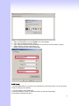
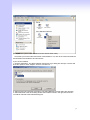
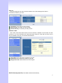
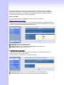
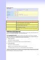
1. On the desktop, Please enter start -> control panel -> network setting.” Click Properties. The
Network screen will open.
28
(Your particular system will be different from the screen shown here.)
Check that you have an Ethernet network card installed. If not, refer to the card manufacturer’s
documentation and install the card and drivers.
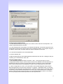
If your card is installed,
1. Click the Add button. The Select Network Component Type dialog box will open. The box will
show four options: Client, Adapter, Protocol, and Service.
2. Select Protocol and click the Add button. The Select Network Protocol dialog box will open.
3. Select Microsoft in the left scrolling window then selects TCP/IP in the right, and click OK.”.
You will be returned to the Network dialog box.
29
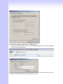
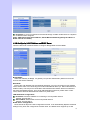
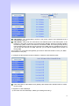
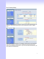
Configuring the TCP/IP Protocol
1. On the Network dialog box Configuration card, select TCP/IP and then click Properties.” The
TCP/IP Properties dialog box will open.
2. On the IP Address tab, click Obtain an IP address automatically. As the DHCP (Dynamic Host
Configuration Protocol) server built into the router is enabled by default, your computer will get an
IP address, subnet mask, and other related IP network settings from the router.
3. On the DNS Configuration tab, click Disable DNS”.
4. Click the Gateway tab.
5. Make the New gateway and Installed gateways fields blank and click OK. A dialog box will pop
up asking you to restart the PC. Click Yes”.
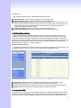
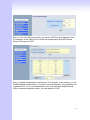
Checking TCP/IP settings
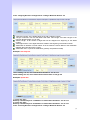
1. After completing the previous steps, click Start -> Run -> and type ipconfig /all. The IP
Configuration window will open. If the PC does not show an IP address in the 222.222.222.51 to
222.222.222.100 range, click the ipconfig /release button to release the current configuration.
Wait a few seconds and click “ipconfig/renew” to get a new IP configuration from the router.
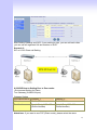
2. If the IP configuration is correct, you will be able to use the PING diagnostic utility built into
Microsoft Windows to ping the router. Click Start -> Programs -> MS-DOS Prompt. A command
mode window will open.Type “ping 222.222.222.1” (default IP of the router) to check the network
connectivity. If both hardware and software are correct, your computer will receive a response
from the router as shown on the next page. If not, verify that the Ethernet cable is connected to
the router properly and the Ethernet port LED on the front panel is lit.
30
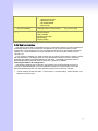
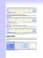
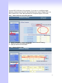
Connecting to the Web Configuration via a Web Browser
1. Launch the Web browser(IE or Firefox). Enter http://222.222.222.1 into the browser Address
window and press the Enter Key
2. An authentication dialog box will open.
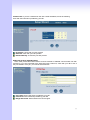
3. If this is a first time setup of the router, type “admin” as the User Name and the Password field
as “admin”. Click OK.(Default username/Password is “admin”)
31
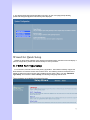
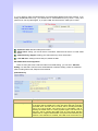
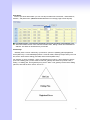
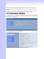
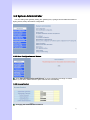
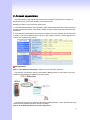
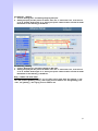
4. The Web Configuration Setup Main Menu will open. On the main page [Setup Wizard],
[Advanced Setup] and [System Information] were displayed.
Wizard for Quick Setup
Wizard for Quick Setup gateway, After finishing the authentication, the Main menu will display 3
parts of configuration, please click “Wizard Setup” to enter quick start:
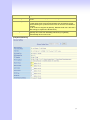
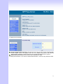
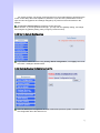
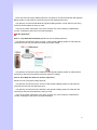
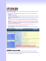
3.1 WAN Port Type Setup
For most users, Internet access is the primary application. The S Series Gateway support the
WAN interface for Internet access and remote access. The following sections will explain more
details of WAN Port Internet access and broadband access setup. When you click “WAN Port
Type Setup” from within the Wizard Setup, the following setup page will be show.
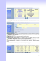
Three methods are available for Internet Access:
32
Fixed IP User: If you are a leased line user with a fixed IP address, fill out the following
items with the information provided by your ISP.
IP Address: check with your ISP provider
Netmask: check with your ISP provider
Default Gateway: check with your ISP provider
ADSL Dial-Up User (PPPoE Enable)
Some ISPs provide DSL-based service and use PPPoE to establish communication link with
end-users. If you are connected to the Internet through a DSL line, check with your ISP to see if
they use PPPoE. If they do, you need to select this item.
User Name: Enter User Name provided by your ISP
Password: Enter Password provided by your ISP.
Retype Password: Enter Password to confirm again.
33
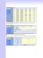
DHCP Client (Dynamic IP): Get WAN IP Address automatically
IP Address: If you are connected to the Internet through a Cable modem line then a dynamic
IP address will be assigned.
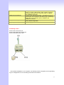
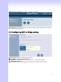
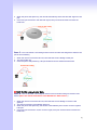
3.2 Configuring NAT or Bridge setting:
Bridge Mode: Select S series Gateway as bridge.
NAT mode: LAN IP Network Configuration
IP Address: Private IP address for connecting to a local private network
(Default: 222.222.222.51).
Subnet Mask: Subnet mask for the local private network (Default: 255.255.255.0).
34
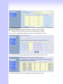
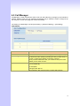
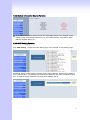
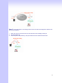
3.3 VoIP Call Protocol Setup
Step1 : Configure VoIP Call Signal Protocols :
User could select H.323 or SIP Protocol, and click “select”
Step2 : configure the numbering with phone/line ports.
Phone Number (FXS): The representation number is the phone number of the telephone
that is connected to Phone port.
Line Number (FXO): Line ports are connected to the extension ports of the PBX system or
the PSTN line. They have a common Line Hunting Group Number. When this number is
dialed, the Gateway system will find a free FXO line connected to PBX. This hunting will skip
all busy lines and absent lines and find only the idle line to the PBX. After the available line is
found, you can hear the dial tone from PBX. After that, you can dial the needed phone
number out through PBX.
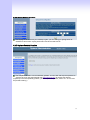
Step3: Let GW Register to Gatekeeper(GK)/SIP Proxy Server
(If user does not have GK/SIP Proxy Server, Please go to Step 4: Outgoing Dialing Plan)
Gatekeeper IP address: There is a gatekeeper address fields. If this gateway does not want
to register to any gatekeeper, just set value 0.0.0.0 to the primary gatekeeper address.
SIP Proxy Server IP addresses: There is a SIP Proxy Server address fields. If this gateway
does not want to register to any SIP Proxy Server, just set value 0 .0.0.0 to the sip proxy
server address.
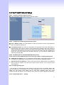
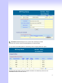
Step 4: Outgoing Dialing Plan
The purpose of “Outgoing Direct Call” setting is to let user create a proprietary dialing plan
when this Gateway is not registered to any H.323 Gatekeeper or any SIP Proxy Server. This
setting can also assign some dialing plan to local ports (including prefix strip, prefix
addition).Through this setting, user can directly map a number to a specific gateway (IP address).
In the “Outgoing Dial Plan” settings.
35
“Leading Number” is the leading digits of the dialing number.
“Min Length” and “Max Length” is the min/max allowed length you can dial.
“Strip Length” is the number of digits that will be stripped from beginning of the dialed number.
“Prefix Number” is the digits that will be added to the beginning of the dialed number.
“Destination” is the IP address of the destination Gateway that owns this phone number.
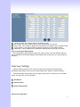
Step 5: Finishing the Wizard Setup
After completing the Wizard Setup, please click “Finish” bottom. The VoIP Gateway will save
the configuration and rebooting Gateway automatically. After 20 Seconds, you could re-login the
Gateway.
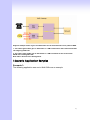
Gateway Setting
Gateway setting include in some of advance setting, SIP Proxy Server (SVR) setting,
Gatekeeper (GK) setting. There are many detail explain follow. Setting in “advance Setting”.
In Advanced Setup, GW provides user two major parts function to configure: One is “Network
Setup”, the other one is “VoIP Call Setup”
SET Wizard
Advance Setup
System Administrator
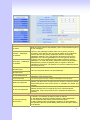
Advanced Configuration:
36
Advanced Setting Label
Network Setup Label
WAN Setting
LAN Setting
Virtual Server
Dynamic DNS
Network Parameters
Sets/changes the WAN port Type like “Fixed IP”, “DHCP Client”
or ”PPPoE”.
Modifies the IP address of the LAN port and setting DHCP Server
parameters.
Remote user can access server such as Web or FTP at you local site
via public IP address can be automatically redirected to local servers
configured with private IP address.
Dynamitic DNS allows you to provide Internet users with a domain
name to access your server.
Network Parameter allows you to modify the access port of gateway.
For example :
Setting HTTP port : 8080
Setting TELNET port is : 8081
(Default HTTP :80, TELNET: 23)
VoIP Setup
VoIP Basic
Dialing Plan
Advanced Setting
The S Series Gateway support 2 / 4 / 8 / 16 / 24 phone/line for SIP
and H.323 VoIP call applications. You can configure these ports from
this menu.
Users could apply any dial policy by setting Dial Plan including
outgoing dial plan and incoming dial plan.
VoIP Gateway support for silence compression, DTMF Relay, Codec
Selection, FAX mode Option,
H323 Register Type and H.323 Fast-Start/Normal-Start function.
FXO AC impedance, Volume Adjustment, RRQ TTL, RFC2833
Payload, IP TOS,..etc
Hot Line Setting
Let user can set up “hotline” to dial the phone number automatically.
Port Status
Display the telephone interface status
Traffic Monitor
Display and Monitor the voice traffic and data traffic.
System Administration:
37
Management Label
Save Configuration
You can save configuration and restart the gateway with the default
configuration or with the current running configuration.
Access Control
Users can Sets/changes the administrator password..
Set to Default
You can restart the gateway with the default configuration.
Backup/Restore
Configuration
User can backup the configuration file of Gateway to PC or Restore the
configuration file from PC.
Display Software version, WAN Type, VoIP Status, VoIP Codec, Phone
Interface and System Tim.
SNTP (Simple Network Time Protocol) Configuration for synchronizing
gateway clocks in the global Internet.
System Information
SNTP Setting
Syslog Setting
Gateway can sends log information to Syslog Server by UDP ports 514.
Capture Packets
The gateway supports packets capture and save the packets to your PC.
User can use Network Protocol Analyzer “Ethereal” to analysis the
packets. (Free down load from http://www.ethereal.com/)
4.1 Network Configuration
4.1.1 WAN Port Type Setup
For most users,Internet access is the primary application. The S Series Gateway support the
WAN interface for Internet access and remote access. The following sections will explain more
details of WAN Port Internet access and broadband access setup. When you click “WAN Setting”,
the following setup page will be show. Three methods are available for Internet Access.
Static IP
PPPoE
DHCP
38
Static IP:
You are a leased line user with a fixed IP address; fill out the following items with the
information provided by your ISP.
IP Address: check with your ISP provider
Subnet mask: check with your ISP provider
Default Gateway: check with your ISP provider
PPPoE for ADSL
Some ISPs provide DSL-based service and use PPPoE to establish communication link with
end-users. If you are connected to the Internet through a DSL line, check with your ISP to see if
they use PPPoE. If they do, you need to select this item.
User Name: Enter User Name provided by your ISP
Password: Enter Password provided by your ISP.
Retype Password: Enter Password to confirm again.
DHCP Client (Dynamic IP): Get WAN IP Address automatically
39
IP Address: If you are connected to the Internet through a Cable modem line then a dynamic
IP address will be assigned.
(Note : WAN port display the IP address, Subnet Mask and Default gateway IP address if
DHCP client is successful)
4.1.2 Configuring LAN IP Address and DHCP Server
There are two kinds of network feature to configure: Bridge Mode and NAT Mode
Bridge Mode:
Select this Gateway as Bridge. Let gateway Lan port like Switch/HUB. (WAN Port and LAN
Port use the same IP address)
NAT Mode:
Each of the VoIP Gateway has two Ethernet interfaces, one is for connecting to local network
users, and the other is for connecting to an external broadband device (i.e. DSL modem/router or
Cable modem). The LAN port is connected to the local Ethernet network. WAN is connected to
the external broadband device. The LAN IP address/subnet mask is for private users or NAT
users, and the WAN IP address/subnet mask is for public users.
LAN IP Network Configuration:
IP Address: Private IP address for connecting to a local private network
(Default: 222.222.222.1).
Subnet Mask: Subnet mask for the local private network
(Default: 255.255.255.0).
DHCP Server Configuration:
DHCP stands for Dynamic Host Configuration Protocol. It can automatically dispatch related IP
settings to any local user configured as a DHCP client. The DHCP server supports up to 253
40
users (PCs) on
Yes: Enables the DHCP server. No: Disables the DHCP server.
Start IP Address: Sets the start IP address of the IP address pool.
End IP Address: Sets the end of IP address in the IP address pool.
DNS Server IP Address: DNS stands for Domain Name System. Every Internet host. must
have a unique IP address, also they may have a human friendly, easy to remember name
such as www.yahoo.com. The DNS server converts the human friendly name into it’s
equivalent IP address. (Default: None)
Primary IP Address: Sets the IP address of the primary DNS server.
Secondary IP Address: Sets the IP address of the secondary DNS server.
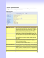
4.1.3 Virtual Server Setup
“Natural firewall” allows requests for Internet access from the local network. However, any
request from the Internet to the local network is blocked. By setting the Virtual Server function,
computers outside the Intranet are allowed to access specific ports of local client. The Virtual
Server Port Table may be used to expose internal servers to the public domain or open a specific
port number to internal hosts. Internet hosts can use the WAN IP address to access internal
network services, such as FTP, WWW, Telnet etc.
How to set a Virtual Server
The following example shows how an internal FTP server is exposed to the public domain. The
internal FTP server is running on the local host addressed as 222.222.222.100.
Private IP: Specifies the private IP address of the internal host offering the service
Public Port: Specifies which port should be redirected to the internal host..
Private Port: Specifies the private port number of the service offered by the internal host.
Apply: Click here to add the port-mapping entry and enable the service.
4.1.4 Dynamic DNS
DDNS is a service that maps Internet domain names to IP addresses. DDNS serves a similar
purpose to DNS: DDNS allows anyone hosting a Web or FTP server to advertise a public name
to prospective users. Unlike DNS that only works with static IP addresses, DDNS works with
41
dynamic IP addresses, such as those assigned by an ISP or other DHCP server. DDNS is
popular with home network, who typically receive dynamic, frequently-changing IP addresses
from their service provider. To use DDNS, one simply signs up with a provider and installs
network software on their host to monitor its IP address.
How to use DDNS
First: you should register a new DDNS service account from this web site:
http://www.dyndns.com/newacct
(Attention, if you use static IP address, you can’t set DDNS in gateway. Use DDNS and Static IP
at the same time, the dyndns will stop your DDNS service. Dyndns support DDNS service is Free,
one account can create 5 different DDNS Domain Name )
User Name: Input your DDNS User Name
Password: Input your DDNS Password
Domain Name: Input you set from your DDNS.(ie.gateway.gotdns.com)
DNS Server IP: Input your DNS Server IP.
4.1.5 Network Management
Network Management,, access port configuration allows you to modify the HTTP port or
TELNET port for accessing VoIP gateway
(Default Parameter : HTTP Port is 80 ; TELNET Port is 23)
Http Server Port: Input you want to change Web access port (Default is 80)
Telnet Server Port: Input you want to change telnet access port (Default is 23)
42
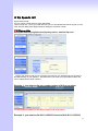
4.2 VoIP Setup
Gateway support 2 VoIP protocol - H.323 / SIP, you can register to H.323 Gatekeeper or SIP
proxy server. Gateway is not a softswitch, it only can use 1 VoIP protocol (SIP/H.323) at the
same time! If you don’t register GK or Proxy server, you can make Peer to Peer call by IP address
or domain name (Setting Dialing plan).
4.2.1 H.323 Setup
Gateway H.323 protocol support H.323 (v2/v3/v4), H.225, Q.931, H.245 and RTP/RTCP. Don’t
support H.235 security, can’t use H.235 security Authentication Username / Password. H.323
protocol is not good at pass NAT/Firewall, the best way is installed gateway on Public IP Address
when it use H.323.If you want to under NAT, gateway support NAT pass function when you use
the same S Series Gateway. Other band gateway doesn’t promise this function can work fine!
1. Select H.323 protocol, if you use S1600/S2400 Series, you can select different page to setting
port number or others.
2. Configure the numbering with FXS / FXO ports.
(Depending on model: S1600 have 16 voice channels for setting, S2400 have 24 voice channels
for setting)
43
FXS Number: The representation number is the phone number of the telephone that is
connected to FXS port.
FXO Number: FXO ports are connected to the extension ports of the PBX system or the
PSTN line. They have a common Line Hunting Group Number. When this number is dialed,
the Gateway system will find a free FXO line connected to PBX. This hunting will skip all busy
lines and absent lines and find only the idle line to the PBX. After the available line is found,
you can hear the dial tone from PBX. After that, you can dial the needed phone number out
through PBX.
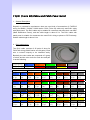
(Port number is in comparison with gateway port number. White Port socket is “FXO” port, Black
Port socket is “FXS” port.)
3. Configure the ANI (Answer Number Indication) / Caller ID of the FXS/FXO ports.
ITSP needs ANI for authorization when gateway calls Off-Net call to PSTN number or mobile
phone number.
4. Register to H.323 Gatekeeper
(If user does not have Gatekeeper, Please go to Dialing Plan Policy)
44
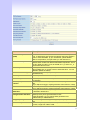
H.323 Parameters Label
H.323 ID
Primary Gatekeeper
IP Address
Secondary Gatekeeper
IP Address
Sets the unique name of this Gateway, that is communicated as part of
H.323 messaging..
There are two gatekeeper address fields, one is primary, the other
secondary. If this gateway does not want to register to any gatekeeper,
just set value 0 to the primary gatekeeper address. If the primary
gatekeeper address is not 0, the gateway will register to the primary
gatekeeper. If the second gatekeeper is not 0, the gateway will try to
register to the second gatekeeper when failed to register to primary
gatekeeper, i.e. if both the primary gatekeeper and second gatekeeper
addresses are present, the gateway will try to register to these two
gatekeepers respectively. The gateway can have the gatekeeper backup
function by this way.
Primary
Gatekeeper
Domain Name
Secondary Gatekeeper
Domain Name
Let user use Domain Name of H.323 Gatekeeper.
H.323 Gatekeeper ID
The Gatekeeper ID; usually do not need to set this field unless the
gatekeeper must need this value.
Voice Cap Prefix
Let user set prefix number in RRQ nonstandard voice cap entry.
RAS Port Adjustment
Q.931 Port Adjustment
In H.323 standard the RAS default port number is 1719. The VoIP
gateway provides user to change RAS port number to meet the network
environment.(Some area carrier blocks or forbidden the default port
number)
In H.323 standard the default Q.931 port number is 1720. The VoIP
gateway provides user to change Q.931 port to meet the network
environment. (Some area carrier blocks or forbidden the default port
number)
H.323 Call Pass through NAT
H.323 Pass Through
NAT method
1. Disable : The Gateway operates in public IP address
2. Auto Detection: When the Gateway register to GNU Gatekeeper /
H.323 Gatekeeper (SK Series), please select this option.
3. Manual Setting: When the Gateway registers to H.323 Gatekeeper
and operate under NAT (enable DMZ), please select this option and key
in IP address.
45
H.323 VoIP Advanced Configuration
There are many H.323, VoIP, Codec and other more detail Setting, you can set in “Advance
Setting”. For SIP and H.323, there are a little different in advance setting. There are 3 different
parts to setting about VoIP, Telephone and network.
[Advance Setting]
Item
Description
DTMF Relay for H.323:
After the VoIP call is connected, when you dial a digit, this digit is
sent to the other side by DTMF tone. There are two methods of
sending the DTMF tone. The first is “in band”, that is, sending the
DTMF tone in the voice packet. The other is “out band”, that is,
sending the DTMF tone as a signal. Sending DTMF tone as a
signal could tolerate more packet loss caused by the network. If
this selection is enabled, the DTMF tone will be sent as a signal.
This selection could force the Gateway to use normal start mode
(default mode) or fast start mode when establishing a VoIP call.
Many other gateways only support normal start mode, enable this
selection when it is necessary. The default is disabled (using fast
start mode).
This selection could force the Gateway to use H.245 Tunneling
when establishing a VoIP call The default is disabled (using fast
start mode).
T.30/T.38 real-time FAX compliant Voice/FAX auto-switch. The
T.38 is a “Real Time Group 3 Fax Communication over IP
network” format. That’s meaning it’s a protocol for Fax over IP.
You have to enable this function
(T.38 mode isn’t support all gateway, different band use T.38 have
a little change, it maybe let T.38 FAX Error)
H.323 Mode:
H.323 H.245 Tunneling:
FAX Mode Option:
H.323 RRQ TTL:
There are 2 choices for this setting. “Gateway” means it will act as
the VoIP gateway. “Terminal” means it will act as the IP phone
terminal.
This command configures the number of seconds that the
gateway should be considered active by the H.323 gatekeeper.
The gateway transmits this value in the RRQ message to the
gatekeeper. The default value is “0”.
H.323 Autoanswer:
When a VoIP call is incoming, the Gateway will ring a specific
H.323 Registration type:
46
MAC Authentication:
Watchdog:
phone set. The H.323 call signaling part could be connected or
alerting during this ringing period. If this selection is enabled, the
H.323 signaling part is connected during the ringing period. The
benefit of this situation is that the remote side could hear the
status of the specific port. That is, the remote side will hear ring
back tone if the Gateway is really ringing the phone set. If the
phone set is busy, the remote side will hear busy tone. The
disadvantage of this situation is that the H.323 connected time is
not the real voice call connected time. So, if billing is recorded for
this Gateway, this function should be disabled.
Some Gatekeeper register need UA send MAC address to
Authentication, you need enable this function.(Default is disable).
When your gateway shutdown, or something happen that made
gateway can’t work fine. Watchdog will reboot your gateway
automatically when it can’t work.
[Telephone Advance]
47
Item
Description
Silence Compression:
(VAD)
If this function is enabled, when silence is occurred for a period of
time, no data will be sent across the network during this period in
order to save bandwidth.
(If you use Asterisk, please disable Silence Compression, it
maybe make you call disconnect.)
The Codec is used to compress the voice signal into data
packets. Each Codec has different bandwidth requirement. There
are four kinds of Codec, G.723, G.729AB, G.711_u and G.711_A.
The default value is G.723.
When you use the VoIP call, you will heard “DuDu” voice that is
dial complete tone. If you don’t want to heard that tone , you can
disable it.(default is enable).
Setting Termination key to speed up VoIP dial. Select “*” or “#” to
Termination key.
The FXS provides 600/900 OHM impedances for selection.
Voice Codec option:
Dial Complete Tone:
Dial Termination key:
FXS Impedance:
FXO AC Impedance:
Phone (Line) in/out
volume:
FXO Tx/Rx Gain:
UK PSTN release tone
detection:
FXO/FXS Flash detection
and generation duration :
Ring Frequency:
DTMF tone power:
FXO Transmit Hybrid:
The FXO provides wild and complex ac termination impedances
for selection.
You can adjust the Phone (Line) in/out volume, range from -9db to
9db
(If you adjust too bigger, maybe generation some ECHO or noise)
You can adjust the FXO Tx/Rx Gain , range from -6db to 6db.
(If you adjust too bigger, maybe generation some ECHO or noise)
When you use the Gateway to UK, you can Enable this selection
to detection release tone
Flash Detection: Let you change flash detection (milliseconds) of
Gateway when phone generate flash to FXS.
Flash Generation: Let you change flash generation time
(milliseconds) for PBX detection.
You can configure how long the Ring Frequency do you want to
use.
Sometimes you input DTMF, but no request. You can adjust this
function, range from -6db to +6db.
ECHO cancellation adjust, 3 mode setting to solve ECHO
problem, default is Mode 1. If you have echo problem, try to select
48
other Option.
FXO Ringer Voltage
Threshold:
FXO Ringer Voltage
filter:
FXS Battery Reversal
Generation:
FXO Answer Supervision
Line Silence Disconnect:
FXO Answer Delay Time
FXO Answer Mode
Sometime you use FXO connect to PSTN/PBX can’t be pick up
the call. PSTN/PBX can’t detection FXO voltage, you can adjust
this function. Default is low.( Low : 16.5 Vrms Medium: 24 Vrms
High: 49.5 Vrms)
Some vendor’s PBX generates the leakage voltage from
extension port. That will mislead the FXO become Off-hook
status. This function was set to avoiding a leakage voltage signal
is detected as ring coming.
Some Payphone need Battery Reversal to count call money.
Gateway FXS can generation that Battery Reversal. If you don’t
use this function , don’t enable it.
Enable battery reverse to detect polarity from PSTN line. The
PSTN line can send. H.323 case: Sending the Q.931 connect
signal to caller when detecting polarity reverse from PSTN Line.
SIP case: Sending the 200 OK connect signal to caller when
detecting polarity reverse from PSTN Line.
Voice Detection: when the FXO connect PSTN/PBX, gateway will
detection the PSTN/PBX send voice , it will send Q.931 connect
or SIP 200 ok.
When FXO call have silence, the call will disconnect
automatically. {Default is Disable}
Some PSTN/PBA when call incoming can’t pick up first time. It
need delay few second time. You can set FXO pick up call delay
time.(default is 0)
FXO Answer Mode Concept:
When user calls the PSTN line which was connected with the
FXO port, there are three answer mode for user to configure.
1. Ringing Answer Mode (Default Setting): FXO answer the call
once the ring coming from PSTN line.
2. Connecting Answer Mode:
Case A: “Hot Line Number” was NOT assigned in the FXO
port. FXO answer the call once the ring come from PSTN
line.
Case B: “Hot Line Number” was assigned and the Hot line
number belongs to remote VoIP device.
In this case, FXO port will not answer (off-hook) the PSTN till
the user picks up the call.
(Note: This case can avoid charging for the Local PSTN call
when the remoting VoIP devic still ring.)
Case C: “Hot Line Number” was setting and the Hot line
number was assigned to another FXS port in same Gateway.
FXO port will not answer (off-hook) till the Phone (connected
to the FXS port) was picked up by user.
(Note: This case can avoid the Local PSTN charge when the
FXS port still ring.)
3. Non Answer Mode: FXO will NOT answer the call in any time.
(Note: Some ITSP only let the FXO for termination function,
they do not user use the FXO port for origination)
49
[Network Advance]
Item
Description
Smart-QoS:
If this function is enabled, when VoIP call is occurred, the other
data will be automatically reduced traffic which across the internet
in order to guarantee the voice bandwidth.
Bandwidth control:
You can configure your bandwidth what the Max byte of download
and upload of ADSL modem rate.
Setting G.723 / G.729 voice compression size. Quality and Packet
size can adjust by you want.
G.723/G.729 Bandwidth:
IP TOS:
Some Router support TOS(Type of Service), when you enable the
TOS function, the router will process those packets firstly.(default
is disable)
50
4.2.2 SIP Setup
Gateway SIP support SIP(RFC3261), SDP(RFC2327), RFC2833, STUN(RFC3489), Symmetric
RTP, outbound proxy, ENUM(RFC2916),and RTP/RTCP.SIP NAT pass through Function can
support 80% NAT/Firewall that you don’t setting DMZ/Virtual server in router or Firewall.
1. Select “SIP Protocol”
2. SIP number / account (username) and Password Setting: Please fill out the SIP account
including username / password from ITSP.
(Note: support digits and character base SIP Account / username, some SIP Server use character
username to login, and a number to call number( ie. VoIPBuster) , if your server don’t support this,
number/Account are the same, please input the same username )
Number: Input SIP Number(Username), if your server support account and number
(different),input the number, else number/account are the same username.
Reg: let your sip account register SIP Server, click this option.
Account: Input SIP account(Username), if your server support account and number
(different),input the number, else number/account are the same username.
Password: Input Password that ITSP support.
Use Public Account: This allows gateway can use single SIP account for multiple ports.
User input the only one account in port one field for registering the ITSP.
51
SIP Hunting Table: This allows gateway can answer SIP call from internet by Hunting. For
example: Port 2-7 are hunting for the Port 1 SIP account. When port 1 are on call, the other
one SIP call from internet will ring port 2.S200/400/800 Series hunting table is use click box.
3. SIP Proxy Server setting, setting SIP proxy server register information.
(If user does not need register SIP Proxy Server, Please go to Dialing Plan Policy)
SIP Proxy Server Label
SIP Proxy Server Setting
1. Enter the SIP service IP address or domain name in this field (the
domain name that comes after the @ symbol i n a full SIP URI).
2. Use Net2Phone Service Provider
SIP Domain
1. Enter the SIP realm in this field
Register Interval Setting
This field sets how long an entry remains registered with the SIP
register server. The register server can use a different time period.
The Gateway sends another registration request after half of this
configured time period has expired.
SIP Authentication
Enable or Disable MD5 Authentication with SIP Proxy Server
52
4. If your gateway under the NAT/Firewall, you should setting different NAT Pass function. if you
setting STUN/Outbound Proxy, you should have a STUN/Outbound proxy server. If they can’t
pass NAT or one way talk happen, try to open “DMZ” and virtual server “5060” port in router.
Symmetric RTP: default use Nat pass function.
STUN Client: setting your STUN server information, default STUN server is FWD STUN
server.
Outbound Proxy Support: Setting your Outbound Proxy server information.
Local SIP Port:: setting local use SIP port, default is 5060.
SIP VoIP Advanced Configuration
There are many SIP VoIP, Codec and other more detail Setting, you can set in “Advance
Setting”. For SIP and H.323, there are a little different in advance setting. There are 3 different
parts to setting about VoIP, Telephone and network.
[VoIP Advance]
Item
Description
DTMF Relay for SIP:
After the VoIP call is connected, when you dial a digit, this digit is sent
to the other side by DTMF tone. There are three methods of sending
the DTMF tone. The first one is “in band”, that is, sending the DTMF
tone in the voice packet. The second one is “RFC2833”, that is,
sending the DTMF tone as a RTP payload signal. The third one is
“SIP Info”, that is, sending the DTMF tone as a SIP signal. Sending
DTMF tone as a signal could tolerate more packet loss caused by the
network. If this selection is enabled, the DTMF tone will be sent as a
53
signal.
RFC2833 Payload:
FAX Mode Option:
Watchdog:
Adjust RFC2833 DTMF payload value, range from 96 to 127, default
is 101.
T.30/T.38 real-time FAX compliant Voice/FAX auto-switch. The T.38 is
a “Real Time Group 3 Fax Communication over IP network” format.
That’s meaning it’s a protocol for Fax over IP. You have to enable this
function
(T.38 mode isn’t support all gateway, different band use T.38 have a
little change, it maybe let T.38 FAX Error)
When your gateway shutdown, or something happen that made
gateway can’t work fine. Watchdog will reboot your gateway
automatically when it can’t work.
[Telephone Advance]
54
Item
Description
Silence Compression:
(VAD)
If this function is enabled, when silence is occurred for a period of
time, no data will be sent across the network during this period in
order to save bandwidth. (If you use Asterisk, please disable
Silence Compression, it maybe make you call disconnect.)
The Codec is used to compress the voice signal into data
packets. Each Codec has different bandwidth requirement. There
are four kinds of Codec, G.723, G.729AB, G.711_u and G.711_A.
The default value is G.723.
When you use the VoIP call, you will heard “DuDu” voice that is
dial complete tone. If you don’t want to heard that tone , you can
disable it.(default is enable).
Setting Termination key to speed up VoIP dial. Select “*” or “#” to
Termination key.
The FXS provides 600/900 OHM impedances for selection.
Voice Codec option:
Dial Complete Tone:
Dial Termination key:
FXS Impedance:
FXO AC Impedance:
Phone (Line) in/out
volume:
FXO Tx/Rx Gain:
UK PSTN release tone
detection:
FXS/FXO Flash detection
and generation duration :
Ring Frequency:
DTMF tone power:
The FXO provides wild and complex ac termination impedances
for selection.
You can adjust the Phone (Line) in/out volume, range from -9db to
9db.
(If you adjust too bigger, maybe generation some ECHO or noise)
You can adjust the FXO Tx/Rx Gain , range from -6db to 6db.
(If you adjust too bigger, maybe generation some ECHO or noise)
When you use the Gateway to UK, you can Enable this selection
to detection release tone
Flash Detection: Let you change flash detection (milliseconds) of
Gateway when phone generate flash to FXS.
Flash Generation: Let you change flash generation time
(milliseconds) for PBX detection.
You can configure how long the Ring Frequency do you want to
use.
Sometimes you input DTMF, but no request. You can adjust this
function, range from -6db to +6db.
55
FXO Transmit Hybrid:
FXO Ringer Voltage
Threshold:
FXO Ringer Voltage
filter:
FXS Battery Reversal
Generation:
FXO Answer
Supervision:
Line Silence Disconnect:
FXO Answer Delay Time
FXO Answer Mode
ECHO cancellation adjust, 3 mode setting to solve ECHO
problem, default is Mode 1. If you have echo problem, try to select
other Option.
Sometime you use FXO connect to PSTN/PBX can’t be pick up
the call. PSTN/PBX can’t detection FXO voltage, you can adjust
this function. Default is low.( Low : 16.5 Vrms Medium: 24 Vrms
High: 49.5 Vrms)
Some vendor’s PBX generates the leakage voltage from
extension port. That will mislead the FXO become Off-hook
status. This function was set to avoiding a leakage voltage signal
is detected as ring coming.
Some Payphone need Battery Reversal to count call money.
Gateway FXS can generation that Battery Reversal. If you don’t
use this function, don’t enable it.
Enable battery reverse to detect polarity from PSTN line. The
PSTN line can send. H.323 case: Sending the Q.931 connect
signal to caller when detecting polarity reverse from PSTN Line.
SIP case: Sending the 200 OK connect signal to caller when
detecting polarity reverse from PSTN Line.
Voice Detection: when the FXO connect PSTN/PBX, gateway will
detection the PSTN/PBX send voice , it will send Q.931 connect
or SIP 200 ok.
When FXO call have silence, the call will disconnect
automatically. {Default is Disable}
Some PSTN/PBA when call incoming can’t pick up first time. It
need delay few second time. You can set FXO pick up call delay
time.(default is 0)
FXO Answer Mode Concept:
When user calls the PSTN line which was connected with the
FXO port, there are three answer mode for user to configure.
4. Ringing Answer Mode (Default Setting): FXO answer the call
once the ring coming from PSTN line.
5. Connecting Answer Mode:
Case A: “Hot Line Number” was NOT assigned in the FXO
port. FXO answer the call once the ring come from PSTN
line.
Case B: “Hot Line Number” was assigned and the Hot line
number belongs to remote VoIP device.
In this case, FXO port will not answer (off-hook) the PSTN till
the user picks up the call.
(Note: This case can avoid charging for the Local PSTN call
when the remoting VoIP devic still ring.)
Case C: “Hot Line Number” was setting and the Hot line
number was assigned to another FXS port in same Gateway.
FXO port will not answer (off-hook) till the Phone (connected
to the FXS port) was picked up by user.
(Note: This case can avoid the Local PSTN charge when the
FXS port still ring.)
6. Non Answer Mode: FXO will NOT answer the call in any time.
(Note: Some ITSP only let the FXO for termination function,
they do not user use the FXO port for origination)
56
[Network Advance]
Item
Description
Smart-QoS:
If this function is enabled, when VoIP call is occurred, the other
data will be automatically reduced traffic which across the internet
in order to guarantee the voice bandwidth.
You can configure your bandwidth what the Max byte of download
and upload of ADSL modem rate.
Setting G.723 / G.729 voice compression size. Quality and Packet
size can adjust by you want.
Some Router support TOS(Type of Service), when you enable the
TOS function, the router will process those packets firstly.(default
is disable)
Bandwidth control:
G.723/G.729 Bandwidth:
IP TOS:
4.2.3 Direct call (Peer to Peer) setup
If you don’t registered Gatekeeper or SIP proxy server, you can make call by Peer to Peer. For
SIP or H.323, setting the dialing plan, and can make direct call.
Overview of the Dialing Plan
The “Dialing plan” need setting when the user use the method of Peer-to-Peer H.323 (SIP)
VoIP call or registering H.323 Gatekeeper (SIP Proxy Server) Mode. The H.323(SIP) Dialing Plan
has two kinds of directions: Outgoing (call out) and Incoming (call in).
1. Outgoing Dial Plan:
Peer-to-Peer Call Mode: Effective
Registering to H.323 Gatekeeper (SIP Proxy Server) Mode: Effective
2. Incoming Dial Plan:
Peer-to-Peer Call Mode: Effective
Registering to H.323 Gatekeeper (SIP Proxy Server) Mode:
The leading number would register to H.323 Gatekeeper (SIP Proxy Server)
When you use direct call, you must setting your VoIP protocol firstly. Use direct call, you should
setting the same protocol both of UA. Both of UA must support dial plan function. Some ATA don’t
support Dialing plan, it maybe let direct call failed.
57
In the “Outgoing Dial Plan Configurations” settings: Maximum Entries : 50
“Outbound number” is the leading digits of the call out dialing number.
“Length of Number” has two text fields need filled: “Min Length” and “Max Length” is the
min/max allowed length you can dial.
“Delete Length” is the number of digits that will be stripped from beginning of the dialed
number.
“Add Digit Number” is the digits that will be added to the beginning of the dialed number.
“Destination IP Address / Domain Name” is the IP address / Domain Name of the destination
Gateway that owns this phone number.
“Destination Port” is port of the destination gateway use.(Default is 5060)
Example1: Normally Dial
1.001x leading call out, call to Destination IP address: 211.22.3.14
2.002x leading call out, call to Destination Domain Name: h.323.gw.net
Example2: Speed Dial
1. If user dial “401”,
Gateway automatically dial “1334588712” to Destination IP address: 211.22.3.14
2. If user dial “402”,
Gateway automatically dial “2212345612” to Destination IP address: 211.21.2.76
In the “Incoming Dial Plan Configurations” settings: Maximum Entries : 50
58
“Inbound number” is the leading digits of the dialing number.
“Length of Number“ has two text fields need filled: “Min Length” and “Max Length” is the
min/max allowed length you can dial.
“Delete Length” is the number of digits that will be stripped from beginning of the dialed
number.
“Add Digit Number” is the digits that will be added to the beginning of the dialed number.
“Destination Tele port” is “Tel-port”; this is for local dial plan setting phone number.
Example1: Hunting for FXS Port
Port 1: FXS
Port 2: FXS
Port 3: FXS
Port 4: FXS
H.323 (SIP) number “123”call incoming, Port 1 will be ringing.
If Port 1 is busy, Port will be ringing.
If Port 1 and 2 are busy, Port 3 will be ringing.
If Port 1, Port 2 and Port 3 are busy, Port 4 will be ringing.
Example2: Hunting for FXO Port
Port 1: FXO was connected to PSTN.
Port 2: FXO was connected to PSTN.
Port 3: FXO was connected to PSTN.
Port 4: FXO was connected to PSTN.
H.323 (SIP) number “123”call incoming, Port 1 will be off-hook and hear the Dial Tone from
PSTN.
If Port 1 is busy, Port will be will be off-hook and hear the Dial Tone from PSTN.
If Port 1 and 2 are busy, Port 3 will be off-hook and hear the Dial Tone from PSTN.
If Port 1, Port 2 and Port 3 are busy, Port 4 will be off-hook and hear the Dial Tone from
PSTN.
59
Example3: Termination Call to FXO for One-Shoot Call
Port 1: FXO was connected to PSTN (area code is 81xxxxxxxx).
H.323 (SIP) leading number “081x”incoming, and delete the first one digit “0”, and call to
PSTN number.
Example4: Termination Call to FXO
Port 1: FXS
Port 1: FXO was connected to PSTN (area code is 92xxxxxxxx).
Port 1 FXS call to “092x” to PSTN, FXO port will delete the first one digit “0” and call to
PSTN number.
( [x]: mean wild card, 0~9. Speed dial: When you dial over the number, input “#” key can speed
dial call, or you key in number as the length as the “length of number” )
4.2.4 Other VoIP Setting
Hot Line:
You can setting hot line. when the call incoming the hot line port, it will call hot line number
automatically. The hot line call the number via VoIP, so you setting the hot line number must VoIP
number. Usually, you want to FXO port call transfer to FSX, you only setting the FXO hot line to
FXS number.
Port number: Input FXS/FXO want to call hot line number. The call will via VoIP, so the
number must be the VoIP number.
60
Port Status:
Each of port show status table. you can view all port status. like on/off hook , caller/callee IP,
duration , and packet loss. (SB800/S1600/S2400 Series can change page to view all ports)
Port Status Display : This selection will display concurrent call status of this Gateway. The
status information of each voice channel includes codec, dialing number and destination IP
address. The status is refreshed every 3 seconds.
Call Priority:
Gateway have a rule for call Priority, up to down is 1)Hot Line 2)Dialing plan 3)Registered
server(SIP Proxy / H.323 Gatekeeper).When a VoIP call made, Gateway will process by Hot Line
first, then it will check the dialing plan table, last fine Server(SIP/H.323).
For example, if I have a gateway , and It is registered a proxy server, I don’t setting any others
(Hot Line or dialing plan.). when I make a VoIP call, gateway will check Proxy server. Now,, I
setting 1~2 dialing plan, and registered proxy server. When I call, gateway will check the dialing
plan first, then find the proxy server. And so on…..
61
4.3 SIP Proxy Server (SVR) Setup
The SVR200/SVR400/SVR800 Series, a Hybrid SIP Proxy Server, registers and authenticates
users, and routes calls between user agents. With SVR400/SVR200/SVR800 Series SIP Server,
you can use SIP Agents, SIP soft phones, and SIP Gateways for VoIP communications. The
SVR400/SVR200/SVR800 Series also provide Trunk Route capability to call Least Cost Route to
ITSP or PSTN line. Otherwise SVR400/SVR200/SVR800 Series were implemented telephone
interface connected with PSTN, PBX or telephone set for SIP Communication.
1. Select SIP Proxy Server option and setting Proxy server.
62
2. Setting Proxy Parameter
Register Expired Time(seconds): This field sets how long an entry remains registered with
the SIP register server. The register server can use a different time period. The Gateway
sends another registration request after half of this configured time period has expired.
SIP Server Port: Setting the Proxy service Port, default port is 5060.
3. Setting Authentication, if you want to use MD5 Authentication , add user and password in table.
63
Enable/Disable MD5 Authentication: If you want to UA registered SVR have Authentication,
Enable this option.
Add Username/Password: Add Username / Password for Authentication.
(Max 250 username / password and Max username/password is 30 digit)
4. If you want to view gateway registered information, select “Register UA” option.
5. If you want to view CDR information (Real Time), select “CDR (Real Time)” option.
6. If you want to know what is the TOP (Max 20), select “call statistic” option
64
7. If you want to register Multi-SIP Proxy Server, select “trunk” option.
ITSP Trunk: There are 4 trunk lines for user t configure. Each trunk have two types:
A. ITSP registering: This SVR can register to another one ITSP Proxy Server for call
international calls to save the call cost.
65
Termination Trunk: Setting the Proxy service Port, default port is 5060.
This SVR can route the calls to terminate gateway for call termination.
8. If you want to set Dialing Rule for Call Routing, select “Outgoing Dial Rule” option.
Outgoing Dial Rule Setting: SVR can register to another one ITSP Proxy Server for call
international calls to save the call cost.
66
Least Cost Trunk Route: SVR200 / SVR 400 /SVR 800 series provide 4 Trunk Route Setting
for Off-Net call to ITSP or Termination Gateway. (SVR series can subscribe to most 4 Service
provider)
For example, you can send all international calls through 4 different ITSP by the least call rate.
The feature can select the most effective service provider by call route rule setting.
4.4 H.323 Gatekeeper (GK) Setup
2/4/8 port gateway can embedded H.323 Gatekeeper (GK). GK are both H.323 Gatekeeper
and Gateway at the same box. GK support simple security, 200 UA registered, but it no group call
and H.235 security Authentication.
1. Select Gatekeeper option and setting gatekeeper.
2. Register Gateway, this can view all registered Gateway information.
67
3. Setting simple security, if you want to gateway authentication before registered, you can use
this function.
Gateway IP address: Input you allow registered gateway IP address, if gateway not in this IP
address, they can’t registered.
H.323 ID: Input H.323 ID for Authentication, gateway must send H.323 ID to GK check, H.323
ID just like “Password”.
MAC address: Input you allow MAC address to authentication.
Enable/Disable Security Policy: if you enable the option, you gateway must send security
information to registered GK, even if you don’t set any Security Policy.
Allow/Block Policy: This option allow you can registered GK with Security Policy, but you
don’t set any Security Policy, gateway can registered GK without security information.
(These 3 authentications, you should 1 or all to security your gatekeeper registered. Max 50
Policy)
4. View CDR and Real time CDR, you can select CDR (Real time) option.
5. Call statistic, you can view what is the top when you select this option.
68
6. You can let GK to call other gateway without registered, setting in Pre-granted GW option.
MAX setting 20 gateway.
Gateway IP Address: Input you want to call without registered Gateway IP address
Phone number: Input that gateway call phone number.
7. You can change your gatekeeper RAS port to gateway registered. 5 RAS port can be setting.
RSA Port: Setting H.323 RSA signal port , you can setting 5 different RSA port to Registered.
69
4.5 Call Manager
Call Manager is used to determine which mode your dial calls will go through by two methods to
achieve, PSTN or VoIP. You can manually press Switch Key to switch the mode or simply set up
the dial plan to let the rules judge the mode automatically.
The setting of Call Manager is under [VoIP Setup] -> [Advanced Setting] -> [4x4 Setting]
[4x4 Setting]
Item
Description
Default Mode
Switch Key
The mode which determine which way your calls will go directly
The method to switch two modes.
To switch the mode quickly by pressing the star (*) button once or
the star (*) button twice before you dial any numbers.
Once you have finished the dial, you will hear a beep sound that
notifies you the action is done.
The numbers which are filled in the form will go through the PSTN
line unconditionally.
PSTN Number:
For examples:
Emergent calls, like 911
Zone Numbers, like 02x (the phone numbers start with 02)
70
4.6 System Administrator
You can setting other gateway setting, like gateway time, Syslog that send CDR information to
Syslog server, backup and restore configuration.
4.6.1 Save Configuration and Reboot
Click “Save Configuration and Reboot” to save configuration and begin to restart.
(When you set done, select “Reboot” option will auto save and reboot!)
4.6.2 Access Control
Changing the Administrator Password
71
For security reasons, we strongly recommend that you set an administrator. password for the
router. On first setup the router requires no password. If you don’t set a password the router is
open and can be logged into and settings changed by any user from the local network or the
Internet.
Click Access Control Setup, the following screen will open.
(Guest account , if you use guest account login , you only can view gateway setting, not change
and configure any gateway setting, else you login by Admin account)
4.6.3 Set To Default Configuration
If you want to reboot the router using factory default configuration, click “Apply” then reset
the router’ s settings to default values.
4.6.4 Backup/Restore Configuration to a File
User can Backup the Configuration to a File at Microsoft Operation System. And also restore
the configuration file to the GW from PC.
72
4.6.5 System Information Display Function
Click System Information Display to open the Online Status page. In the example, on the
following page, both PPPoE connection is up on the WAN interface, H323 Status, MAC
address, Register Status, etc….
4.6.6 SNTP Setting Function
Click SNTP Setting to open the Online Status page. In the example, on the following page,
.
Use SNTP Setting—When checked, Gateway uses a Simple Network Time Protocol (SNTP) to
set the date and time . The Gateway synchronizes the Gateway’s time after you select the time
zone. Use SNTP Setting, Select the time zone which Gateway was at.
73
4.6.7 Syslog Setting Function
Use Syslog server to record your Gateway log file. you can setting you syslog server IP
address for this function. Syslog information include the CDR source!
4.6.7 Capture Packets Function
Use “Capturer Packets” to record Gateway packets. You can start and stop the capture then
save the file to PC Use the Ethereal Tool (www.ethereal.com) to analyze the packets.
(if gateway have interoperability problem, you can capture the packet, send to us . we can refer
this packet to bebug.)
74
4.7 Update firmware(For Gateway & GK & SVR)
Gateway can upgrade Firmware via FTP, update firmware can add new function or fix some
bug. If your gateway works fine, you don’t need update any new firmware. The new firmware
maybe let your gateway not stable. you can get the last version firmware on our web site or send
support mail to us, we will mail firmware to you.
Firmware name is “S400.275”, the first name s400 is mean the gateway module. There are 3
module name use different firmware.S200/S400(GK/SVR) are use the Firmware first name
“S400”, S800(GK/SVR) use the “S800”, SB800/S1600/S2400 use the “S2400”. The second name
is the firmware version. For example, “s400.275” is mean that firmware use S200/S400 (GK/SVR)
module, version is 275.
(Gateway update firmware only support use telnet via FTP, no other else upgrade function.)
FTP upgrade Requirement and Process
1. Environment Requirement
PC with FTP Server (Server-U software, 3CDaemon,..)
PC or Notebook witch connected to LAN port of Gateway.
Put the image (firmware) named “s400.xxx” at the assigned folder in FTP Server.
( for example: “s400.270” is version 2.7.0 )
Note: Our company FTP server, you can use it to upgrade
Free FTP server : 61.218.109.83
username: share , password: 19730809
Environment Architecture (Gateway and FTP server are in Internet):
FTP Server
Notebook
VoIP Gateway
WAN Port
LAN Port
Internet
2. Upgrading Process
Notebook Telnet VoIP GW
[Open DOS mode]
->C:> telnet 10.10.10.1 (Default LAN port IP address) (before version 2.6.5)
->C:> telnet 222.222.222.1 (Default LAN port IP address) (after version 2.6.6)
Please select [4] Upgrade Software
75
Please input IP address of FTP server like as : 61.218.109.83
Username : share
Passswd : 19730809
Imagename: s400.271
Upgrade (y/n) : y , then will write the firmware to flash.
(In different module or firmware , maybe have different change)
After writing flash, Please reboot the Gateway.
If the new firmware (image) was most different with the previous version, please push the
76
hardware reset bottom to set to default.
If the VoIP Gateway is in remote site, please use WEB configuration to set to default.
Soundwin Network, Inc. - Headquarters
10F-4, No. 295, Sec. 2, Guangfu Rd.,
Hsinchu City, Taiwan
Tel: +886-3-5733113
Fax: +886-3-5736131
E-mail: [email protected]
Web Site: http://www.soundwin.com
This manual Write by Tony_chi check by gloria
77
Appendix
A FAQ List
1. What is the default administrator password to login to the gateway?
A: By default, your default username is “admin”, default password is “admin” to login to the router.
For security, you should modify the password to protect your gateway against hacker attacks.
2. I forgot the administrator password. What should I do?
A: Press the Reset button on the rear panel for over 5 seconds to reset all settings to default
values. Default username / password is admin / admin.
3. What is the default IP address of the router?
A: The default WAN IP address is 192.168.1.1 with subnet mask 255.255.255.0.
The default LAN IP address is 222.222.222.1 with subnet mask 255.255.255.0.
4. Why is it that I can ping to outside hosts, but not access Internet Web sites?
A: Check the DNS server settings on your PC. You should get the DNS servers settings from
your ISP. If your PC is running a DHCP client, remove any DNS IP address setting. As the router
will assign the DNS settings to the DHCP-client-enabled PC.
5. What is the maximum number of IP addresses that the DHCP server of the gateway can
assign to local PCs?
A: The built-in DHCP server can support 253 IP addresses for local network usage.
6. What is different [set to default] and [Factory set to default]?
A: Factory set to default, you must push RST button until 5 second, gateway will clear all your
setting, and let gateway Wan/Lan port become the factory default(192.168.1.1/222.222.222.1).
When you use setting to default by Web or telnet , it will clear all your setting, but the wan port
setting will be saved. If you remote the gateway, after set to default, you can login gateway again.
No reset the gateway wan port again.
7. What is the Flash?
1. PSTN Call from PSTN to Office PBX and dial the extension 102 go to Gateway
2. Call to Gateway of Home by Hotline.
3. Home user needs call transfer to extension number 101.
78
Dial Flash and Gateway FXS detect and generate the Flash to PBX in Office.
Flash is mean on-hook and off-hook fast switch, on-hook and off-hook duration. It usually use
on PBX system, in place of transfer function key.
4.
8. Why can I call out when the gateway under the NAT?
A: VoIP product almost have NAT Pass through problem. By SIP, there are many NAT Pass
through Function can solve 80% NAT Problem. You can choose STUN/Outbound Proxy/
Symmetric RTP to Pass through NAT, you don’t set any other setting (DMZ/Virtual Server) by
router side. If you use STUN/Outbound Proxy, you must have a STUN/Outbound Proxy Server to
support. If they can’t pass NAT, please open the DMZ/Virtual Server by Router/NAT/Firewall.
9. Why does the one way talk happen?
A: Generally, one way talk happen when use the different codec between VoIP device make call.
Please check and setting the same codec, most one way talk will be solved.
10. Why can I call out by Gateway?
A: Please chick your Gateway is registered SIP Proxy Server (ITSP), and chink your Internet
works fine. Gateway can’t make a call without Internet or SIP Account that from ITSP supply. You
must have a SIP account or know the other Gateway IP/Domain Name, then you can make a
VoIP call.
11. I can’t use web Interface to setting gateway. How can I do?
A: Please check you PC connect the Gateway Lan port or PC and ATA with the same Subnet. If
you PC aren’t at the same Subnet, you can’t Login the gateway Web interface. Else you let your
gateway on Public Internet(Public IP address).when you Lan and Wan can’t login always, try to
set factory default. (Push RST button until 5 second), and try again
12. Why I use asterisk by G.729 sometimes disconnect happen?
A: In asterisk setting VAD must disable, if you open Silence Compression (VAD), it will make call
disconnect happen, please disable the option when you use the asterisk.
13. Can I use re-invite function when server is asterisk?
A: No, our gateway not support this function complete, the new firmware will support re-invite.
14 Why can i register and use after setting?
A: After setting, please save configuration and reboot, after reboot you can use new
configuration.
15. Why I can’t use FAX?
A: The VoIP FAX has 2 mode, one is T.30, another is T.38. T.30 use voice date to FAX, so
usually T.30 FAX by VoIP is work. There are some problem with T.38. Because T.38 is use
protocol and data packet to sand FAX, different platform and device maybe have different change,
that made the T.38 filed. If you can use T.38 to FAX, Please try to use T.30.
79
B SIP Setting VoIPBuster
VoIPBuster Service Using Soundwin VoIP Gateway
The Soundwin S200/S400/S800/SB800/S1600/S2400 VoIP Gateway can register to VoIPBuster
(http://www.voipbuster.com) VoIP service by SIP protocol and also can call SIP calls by
VoIPbuster (http://www.voipbuster.com) service.
Gateway Setting
1. VoIPBuster SIP Proxy Server : sip.voipbuster.com / 5060
2. VoIPBuster STUN Server: stun.voipbuster.com / 5060
3. VoIP Basic -> Setting SIP accounts and Set the Proxy Server and STUN server.
80
How to dial the call?
00 - country code – area code
For example soundwin company phone number is +886-35733113, the dial number is
0088635733113
VoIPBuster Provides Free Land Line (Fixed Line) Calls
81
C Answer supervision
This is designed to help explain and resolve issues of answer supervision from a switch or
PSTN provider that could result in billing for termination calls.
Gateway provides 2 Types of Answer Supervision:
1. Loop-Start Reverse Battery, Reverse battery (also called Polarity Reverse) is when the PSTN
provider reverses the polarity of the battery voltage, for both answer supervision and disconnect
supervision.
2. Voice Detection-based answer supervision is a feature where the Gateway can be configured
to “listen” on the line for different tones and voice. The Gateway sends a “connect” signals out or
“disconnect” signaling using internet.
SIP Application
Case 1: Loop Start Reverse Battery : PSTN Line was set Polarity Reverse:
The gateway can send the “200 OK” SIP signals to Billing System of ITSP, after the user pick
up the Phone and detect the PSTN line answer voltage.
The gateway can send the “200 BYE” SIP signals to Billing System of ITSP, after the user hang
up the Phone and detect PSTN line disconnect voltage.
Case 2: Voice Detection based on answer supervision:
82
PSTN Line was not support Polarity Reverse: The gateway can send the 200 OK SIP signals to
Billing System of ITSP, after the user pick up the Phone and detect the voice.
The gateway can send the 200 BYE SIP signals to Billing System of ITSP, after the user hang
up the Phone and detect the hang up voice.
This type of answer supervision is not 100% accurate. Any voice frequency is detected as
connect, including any intercept or recorded messages.
H.323 Application
Case 1: Loop Start Reverse Battery PSTN Line was set Polarity Reverse:
The gateway can send the “Q.931 connect” H.323 signals to Billing System of ITSP, after the
user pick up the Phone and detect the PSTN line answer voltage.
The gateway can send the “Q.931 Release” H.323 signals to Billing System of ITSP, after the
user hang up the Phone and detect PSTN line disconnect voltage.
Case 2: Voice Detection based on answer supervision
PSTN Line was not support Polarity Reverse:
The gateway can send the Q.931 connect H.323 signals to Billing System of ITSP, after the
user pick up the Phone and detect the voice.
The gateway can send the Q.931 Release H.323 signals to Billing System of ITSP, after the
user hang up the Phone and detect the hang up voice.
This type of answer supervision is not 100% accurate. Any voice frequency is detected as
connect, including any intercept or recorded messages.
83
D Sip Speeds call
Speed Call Concept:
Cut your phone number down to fewer digit dialing!
Life is moving fast - you've got to dial fast. Now you can with Speed Dial. Dial the people you call
most with just dialing fewer digits instead of dialing the full phone number.
SIP Register Mode
Example: Gateway registers to sip proxy server: service.sip.com
What's even better is that you can customize and manage your speed dial phone numbers in
Dial Plan Setting on your gateway! Dial Plan allows you to set up to speed dial numbers that
can be called with the fewer numbers.
Example 1: you want to dial any number instead of 810-any number
The destination IP address is the domain name of sip proxy server
Example 2: you want to dial 86-1111222333 instead of 810-86-1111222333
84
The destination IP address is the domain name of sip proxy server
Example 3: you want to dial 999 instead of 810-86111222333
The destination IP address is the domain name of sip proxy server
85
E Interoperability List
Gatekeeper
GnuGK openH323
Radvision ProLab GateKeeper Simulator, Version 1.0, October 2001
Clarent Gatekeeper
MediaDigm-SureKeepe
Lucent -i Merge GK
SIP Proxy Server
Vovida SIP Proxy Server
SER (SIP Express Router)
Party SIP ServerV0.5.0
Clarent SIP server
Asterisk 0.5.0
SXi SIP server
Gateway:
Welltek 2~8 port GW
ACCEL 2~8 port GW
Cisco 5300 and Cisco 5350 Trunk GW
Cisco ATA -186
MOSA 4 port
CISCO ATA-186
Quintum Tenor A400/A800, AS/AX Series
Antek 2500 series and vsp5004 series
Audiocodes MP-104 FXS
Clarent CPG-101 , CPG-22102Sc
D-Link 4-port gateway
BOSaNOVA Analog Gateways
Trunk Gateway:
Cisco AS5300, 5350
Clarent BHG2500
AudioCodes IPM-260 Board
IP Phone:
ACT LAN phone
TECOM IP PHONE
BCM IP Phone
Cisco 7900 IP Phone
UMEC video phone
86
F RJ21 (Telco 50) Cable and Patch Panel Install
1. General Description
Depend on customer’s requirement, there are two kinds of accessories of FXS/FXO
wiring for SB800 / S1600 / S2400 series: RJ21 (Telco 50) cable only and RJ21 cable
with patch panel. The RJ21 cable only is suitable for customers who have their own MDF
(Main Distribution Frame), and the cable length is about 2.7m. The RJ21 cable with
patch panel is suitable for customers who need RJ11 wiring to phone or PSTN directly,
and the cable length is about 1.6m.
2. RJ21 cable wiring
The RJ21 cable consists of 25 pairs of wires for
FXS/FXO wiring (S2400 series use 24 pairs). Each
wire is colored uniquely to be identified easily.
Basically, the color codes are composed of 2 group
of colors and the color code for each wire and pair
is as the following:
Color Group 1 Blue
Color Group 2 White
Pair 1
Orange
Red
Pair 2
Green
Black
Pair 3
Brown
Yellow
Gray
Purple
Pair 4
Pair 5
Wire 1
Wire 2
Wire 3
Wire 4
Wire 5
Wire 6
Wire 7
Wire 8
Wire 9
Wire 10
Blue-
White-
Orange-
White-
Green-
White-
Brown-
White-
Gray-
White-
White
Blue
White
Orange
White
Green
White
Brown
White
Gray
Pair 6
Pair 7
Pair 8
Pair 9
Pair 10
Wire 11
Wire 12
Wire 13
Wire 14
Wire 15
Wire 16
Wire 17
Wire 18
Wire 19
Wire 20
Blue-
Red-
Orange-
Red-
Green-
Red-
Brown-
Red-
Gray-
Red-
Red
Blue
Red
Orange
Red
Green
Red
Brown
Red
Gray
Pair 11
Pair 12
Pair 13
Pair 14
Pair 15
Wire 21
Wire 22
Wire 23
Wire 24
Wire 25
Wire 26
Wire 27
Wire 28
Wire 29
Wire 30
Blue-
Black
Orange-
Black
Green-
Black-
Brown-
Black-
Gray-
Black-
Black
-Blue
Black
-Orange
Black
Green
Black
Brown
Black
Gray
Pair 16
Pair 17
Pair 18
Pair 19
Pair 20
Wire 31
Wire 32
Wire 33
Wire 34
Wire 35
Wire 36
Wire 37
Wire 38
Wire 39
Wire 40
Blue-
Yellow -
Orange-
Yellow -
Green-
Yellow -
Brown-
Yellow -
Gray-
Yellow-
Yellow
Blue
Yellow
Orange
Yellow
Green
Yellow
Brown
Yellow
Gray
87
Pair 21
Pair 22
Pair 23
Pair 24
Pair 25
Wire 41
Wire 42
Wire 43
Wire 44
Wire 45
Wire 46
Wire 47
Wire 48
Wire 49
Wire 50
Blue-
Purple -
Orange-
Purple -
Green-
Purple -
Brown-
Purple -
Gray-
Purple-
Purple
Blue
Purple
Orange
Purple
Green
Purple
Brown
Purple
Gray
The picture below shows the pair 1 to pair 5 wiring:
3. RJ21 cable with Patch Panel wiring
There are 25 RJ11 ports on patch panel, and each port is marked from 1 to 25 (S2400
series use port 1 to 24).
Each port has a LED indicator on it.
The LED indicator is lighted when
this port is for FXS functionality after
system booting complete. For FXO
port, the LED indicator is not lighted
till PSTN plugged with proper
polarity (RJ11 pin 4 is positive
polarity).
G SB800 / S1600 / S2400 Series module extension
88
install
Introduce:
SB800/S1600/S2400 series, according to different module board and motherboard combine to
8/16/24 port high level gateway. The module board and types are as follows:
Motherboard
SB800
SB800
SB804
SB804
SB808
SB808
Module_1
M800
M800
M804
M804
M808
M808
Module_2
-M800
-M804
-M808
Type
S1600
S2400
S1608
S2412
S1616
S2424
Module group M80x installs:
a.) Open gateway box, let cover on the fixed screws and all take off. Taking down RJ-21 (Telco
50) six angle screws going to, use six angle collets screws. The screwdriver will be more
convenient.
b.) Open the top cover, there is expansion of two groups of DIN41612 model that joins the head
on the motherboard. Please pay attention to two groups of triangular marks on motherboards,
Position of the mark.
89
c.) M80x module will enclose 5 regular posts while producing the goods. Please pay attention to
the position of the triangular mark on the module
d.)Module 1 (the 9~6th port of FXS/ FXO) Must be put in the extension 1 area. Please insert in
the extension 1 area of regular posts 5 inside in a regular hole.
e.)Put and fix the module board on motherboard. Please notice the triangular mark on module
and motherboard is on the same position. Please fix DIN41612 connector is regular and good, at
the same time the regular post totally opens and blocks the module too.
90
f.)To the module 2 (17th ~ 24th FXS/FXO port), repeat step d and e are installed by finishing in
the expanding area.
g.) Open power at this moment, type shown in LCD can know module correct to install.
91
h.)Put back to the top cover, lock all screws of the top cover. Module is installed and finished.
H Gateway value Setting
Phone Volume / Line Volume
Supports user can set DSP volume.
FXO TX /RX Gain
92
Supports multiple levels of gain and attenuation for the transmit and receive paths of DAA.
1. The FXO tx gain enable gain or attenuation in 1 dB increments for the transmit from DAA
site outgoing PSTN site.
2. The FXO rx gain enable gain or attenuation in 1 dB increments for the receive from
PSTN site incoming DAA site.
Note: DAA : Direct Access Arrangement.
I Scenario Application Samples
Scenario 1:
The following application was use in Multi-Office as an example
93
Scenario 2:
SVR and Gateway Setting
Part 1: SVR Setting
94
Step_1: Setting SVR Ports Number that is gateway (SVR) port 1~4.If there are
other gateway registered on SVR, you can call SVR port number (100~400), or
call other gateway registered number. For example, your have a gateway
registered SVR number is 1001, you can call 1001 to SVR port 1 (100), or use
SVR port 1(100) to call gateway 1001.
Step_2: Select SIP Proxy Server option to setting SIP Proxy Server function. Our
SVR is a simple SIP Proxy Server, it support registered and Make call each other.
95
Setp_3: In Proxy Parameter setting, You can set SVR Port and registered time.
For example, in this setting Port is 6000 and registered Expired 900 second.
Default Proxy port is 5060.
Step_4: Setting Authentication, add account. For example, in this setting, you can
Enable/Disable authentication, if you don’t use authentication, every gateway can
registered SVR. If you use authentication, you must add username/password.
Only in username /password table, you can register in SVR.
96
Part 2: Gateway Setting
Step_1: Setting Gateway Port Number, If your SVR use MD5 authentication, you
must input Username/Password that on SVR authentication table to register
SVR.
Step_2: Input Server information. For example, red line cycle is must input field.
Input SVR IP address or domain name, Register Interval time setting as the
same as SVR registered Expired time. If you SVR have MD5 Authentication, you
must enable SIP Authentication.
97
After Setting Gateway and SVR, If your setting is right, you can call each other.
you can see all registered UA and number on SVR.
Scenario 3:
SIP or H.323 Direct call Setting
H.323/SIP How to Setting Peer to Peer mode:
-Environment Setting for DemoTwo Gateway (2/4/8/16/24 port)
Gateway Setting
Information\device Gateway_1
Gateway_2
IP Address
IP:192.168.1.1
IP:192168.1.2
Port Number
Port_1~Port_4:100~103
(Phone Number)
Port_1~Port_4:200~203
(Phone Number)
Attentions: If you want to use P2P (Direct mode), please select the same
98
protocol SIP/H.323 both of the gateway. If you want to use different band
gateway, please check the other band gateway have support Dialing Plan, we
don’t premise all of other band gateway can complete support P2P mode.,
Setp_1:Select SIP/H.323 and setting Number
1. Choose “VoIP Basic”. Login in web interface, and in ”Advance Setting”.
2. Select you wan to use protocol (SIP/H.323).
3. Input you want to use call number.
Setp_2:Setting Dialing plan
99
For Gateway_1 Setting
1. Choose “Dialing plan” and Setting Outgoing Dial plan.
2. Setting dial plan just like picture for demo.”20x” the “x” mean wild card , it can be one
of “0~9” number. And length “3~3”, when you input 3 number and the call will be made.
Destination is the Gateway_2 IP address.
For Gateway_2 Setting
1. choose “Dialing plan” and Setting Outgoing Dial plan.
2. Setting dial plan just like picture for demo.”10x” the “x” mean wild card , it can be one
of “0~9” number. And length “3~3”, when you input 3 number and the call will be made.
Destination is the Gateway_1 IP address.
Step_3:make call each other
1.When you setting 2 gateway done, you can make call by each other. On gateway_1, just
call “200”,and the gateway_2 Port_1 will ringing, then be made a call. And gateway_2 call
“100” , the gateway_1 will ringing, then be made a call.
100
J FXO Answer Mode
FXO Answer Mode Setting
FXO Answer Mode Concept:
When user calls the PSTN line which was connected with the FXO port, there are three answer
mode for user to configure.
7. Ringing Answer Mode (Default Setting): FXO answer the call once the ring coming from
PSTN line.
8. Connecting Answer Mode:
Case A: “Hot Line Number” was NOT assigned in the FXO port. FXO answer the call once
the ring come from PSTN line.
Case B: “Hot Line Number” was assigned and the Hot line number belongs to remote VoIP
device.
In this case, FXO port will not answer (off-hook) the PSTN till the user picks up the call.
(Note: This case can avoid charging for the Local PSTN call when the remoting VoIP devic
still ring.)
Case C: “Hot Line Number” was setting and the Hot line number was assigned to another
FXS port in same Gateway. FXO port will not answer (off-hook) till the Phone (connected to
the FXS port) was picked up by user.
(Note: This case can avoid the Local PSTN charge when the FXS port still ring.)
9. Non Answer Mode: FXO will NOT answer the call in any time.
(Note: Some ITSP only let the FXO for termination function, they do not user use the FXO
port for origination)
SIP Call Connecting Answer Mode
Case B: Hot Line Number” was assigned and the Hot line number belongs to SIP device.
1. When the call com from PSTN to FXO, FXO start the Hot line dialing to remote SIP gateway
2. The phone of remote SIP gateway start ring.
101
3. When the phone was picked up, the remote SIP Gateway sends “SIP 200 OK” signal to FXO
port.
4. Once FXO port receive the “SIP 200 OK” signal, FXO port would off-hook to answer the
PSTN call.
Case C: “Hot Line Number” was setting and the Hot line number was assigned to another FXS
port in same Gateway.
1. When the call com from PSTN to FXO, FXO start the Hot line dialing to FXS port.
2. The phone start ring.
3. Once the phone was picked up, FXO port would off-hook to answer the PSTN call.
H.323 Call Connecting Answer Mode
Case B: Hot Line Number” was assigned and the Hot line number belongs to remote H.323
device.(Note: The remote H.323 device need Disable the “Auto Answer”)
1. When the call com from PSTN to FXO, FXO start the Hot line dialing to remote H.323
gateway
2. The phone of remote H.323 gateway start ring.
3. When the phone was picked up, the remote H.323 Gateway send “Q.931 connect” signal to
FXO port.
4. Once FXO port receive the “Q.931 connect” signal, FXO port would off-hook to answer the
PSTN call.
102
Case C: “Hot Line Number” was setting and the Hot line number was assigned to another FXS
port in same Gateway.
1. When the call com from PSTN to FXO, FXO start the Hot line dialing to FXS port.
2. The phone start ring.
3. Once the phone was picked up, FXO port would off-hook to answer the PSTN call.
103