1
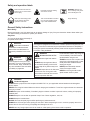
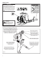
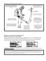
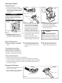
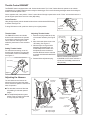
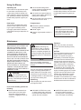
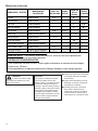
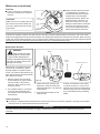
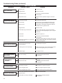
SHINDAIWA OWNER’S/OPERATOR’S MANUAL EB854 BLOWER EB854RT BLOWER EB854RT EB854 WARNING! Minimize the risk of injury to yourself and others! Read this manual and familiarize yourself with the contents. Always wear eye and hearing protection when operating this unit. X750-020454 X750197-1604 1311Ah 0275 ES Printed in Japan Introduction The shindaiwa EB854 has been designed and built to deliver superior performance and reliability without compromise to quality, comfort, safety, or durability. The information contained in this manual describes units available at the time of production. While every attempt has been made to give you the very latest information about your shindaiwa EB854 blower. There may be some differences between your EB854 blower and what is described here. Contents WARNING! The engine exhaust from this unit contains chemicals known to the State of California to cause cancer, birth defects or other reproductive harm. ECHO, Inc. reserves the right to make changes in production without prior notice, and without obligation to make alterations to units previously manufactured. IMPORTANT! Before using this unit, consult local regulations concerning noise restrictions and hours of operation CAUTION! This blower is equipped with a spark-arresting mufÀer 1ever operate this unit without both the mufÀer and spark arrester installed and properly functioning 3A*E 3A*E Attention Statements ............................................. 2 *eneral Safety Instructions ................................... 3 Emission Control ................................................... 5 Unit Description ..................................................... 6 Speci¿cations ........................................................ 6 Assembly ............................................................... 7 Mixing Fuel ............................................................ 9 Filling the Fuel Tank............................................. 10 Starting and Stopping .......................................... 10 Using the Blower ................................................. 13 Maintenance ........................................................ 13 Long Term Storage .............................................. 17 Troubleshooting *uide ........................................ 18 Emission System Warranty ................................. 21 IMPORTANT! The operational procedures described in this manual are intended to help you get the most from this unit and also to protect you and others from harm. These procedures are general guidelines only, and are not intended to replace any safety rules/laws that may be in force in your area. If you have any questions regarding your EB854 blower, or if you do not understand something in this manual, your shindaiwa dealer will be glad to assist you. For additional information, you may also contact shindaiwa at the address printed on the back of this manual. Attention Statements Throughout this manual are special ³Attention Statements´. DANGER! A statement preceded by the triangular attention symbol and the word ³DA1*ER´ contains information that should be acted upon to prevent serious injury or death. WARNING A statement preceded by the triangular Attention Symbol and the word ³:AR1I1*´ indicates a potentially hazardous situation which, if not avoided, COULD result in death or serious injury. IMPORTANT! A statement preceded by the word ³I03OARTA1T´ is one that possesses special signi¿cance. 2 CAUTION! A statement preceded by the word ³CAUTIO1´ contains information that should be acted upon to avoid damaging the unit. NOTE: A statement preceded by the word ³1OTE´ contains information that is handy to know and may make your job easier. Safety and operation labels Read and follow this manual. Failure to do so could result in serious injury. Keep hair and loose clothing clear of the air inlet. Wear eye and hearing protection at all times during the operation of this unit. This unit is intended for outdoor use only and should be used only in well ventilated areas. WARNING: Surface can be hot. Always wear gloves when handling this unit. Finger Severing General Safety Instructions Work Safely Blowers operate at a very high speed and can do serious damage or injury if they are misused or abused. Never allow a person without training or instruction to operate your Blower! Stay Alert <ou must be physically and mentally ¿t to operate this unit safely. WARNING! 1ever make unauthorized modi¿cations or attachment installations. 1ever use attachments not approved by shindaiwa for use on this unit. WARNING! 1ever operate power equipment of any kind if you are tired or if you are under the inÀuence of alcohol, drugs, medication or any other substance that could affect your ability or judgement. IMPORTANT! This engine is equipped with a heat sensor in order to prevent the engine from overheating. If the sensor is activated, engine speed will be reduced to 5,000 (RPM). If the engine speed is automatically reduced, please cool the engine as described in the section "Using the Blower". WARNING! Minimize the Risk of Fire NEVER smoke or light ¿res near the unit. ALWAYS stop the engine and allow it to cool before refuelling. Avoid over¿lling and wipe off any fuel that may have spilled. If fuel leaks are evident, stop using the unit immediately. Fuel leaks must be repaired before using the unit. ALWAYS move the unit to a place well away from a fuel storage area or other readily Àammable materials before starting the engine. NEVER place Àammable material close to the engine mufÀer. ALWAYS inspect the unit for fuel leaks NEVER run the engine without the before each use. During each re¿ll, spark arrester screen in place. check that no fuel leaks from around the fuel cap and/or fuel tank. WARNING! Use Good Judgment ALWAYS wear eye protection that complies with A1SI = 87.1 or your applicable national standard to shield against thrown objects. NEVER run the engine indoors Make sure there is always good ventilation. Fumes from engine exhaust can cause serious injury or death. ALWAYS stop the unit immediately if it suddenly begins to vibrate or shake. Inspect for broken, missing or improperly installed parts. ALWAYS keep the unit as clean as practical. Keep it free of loose vegetation, mud, etc. ALWAYS keep the handles clean. ALWAYS disconnect the spark plug wire before performing any maintenance work. ALWAYS turn off the engine before putting the unit down. When transporting the unit in a vehicle, properly secure it to prevent the unit from over turning, fuel spillage and damage to the unit. NEVER insert any foreign objects into the air intake or outlet opening of the blower while in operation. 3 Safety Labels IMPORTANT! Safety and Operation Information Labels: Make sure all information labels are undamaged and readable. Immediately replace damaged or missing information labels. 1ew labels are available from your local authorized shindaiwa dealer. WARNING! Metal surfaces of crankcase may be hot! Always wear gloves when handling this unit. The Properly Equipped Operator Wear close-¿tting clothing to protect legs and arms. Gloves offer added protection and are strongly recommended. Do not wear clothing or jewelry that could get caught in machinery or underbrush. Secure hair so it is above shoulder level. NEVER wear shorts! Wear hearing protection when operating this unit. Always wear eye protection such as a face shield or goggles while operating this unit. Never operate the blower when visibility is poor. Wear a dust mask to reduce the risk of inhalation injuries. Keep a proper footing and do not overreach. Maintain your balance at all times during operation. Wear appropriate footwear (nonskid boots or shoes): do not wear open-toed shoes or sandals. Never operate the unit while barefoot! Figure 1 4 Always be aware of the strength and direction of the blower discharge stream. Never direct the blower discharge stream toward people or animals! Be Aware of the Working Environment Debris sometimes collects on the blower intake. Never clean out debris from the blower while the engine is running! Make sure bystanders or observers outside the 15m (50-foot) “danger zone” wear 15 METERS Avoid long-term operation in very hot or very cold weather. Never operate the blower if any component parts are damaged, loose, or missing! Be extremely careful of slippery terrain, especially during rainy weather. Never operate this blower on a roof, ledge or ladder. Figure 2 15m Be constantly alert for objects and debris that could be thrown from the air blast and bounced from a hard surface. Reduce the risk of bystanders being struck by Àying debris. Make sure no one is within 15 meters (50 feet)—that’s about 16 paces—of an operating blower. Do not direct the air blast towards bystanders. The high air Àow could blow small objects at great speed causing possible eye injury. Emission Control (Exhaust & Evaporative) EPA 2010 and Later and/or C.A.R.B. TIER III The emission control system for the engine is EM (engine modi¿cation) and, if the second to last character of the Engine Family on the Emission Control Information label (sample below) is ³C´, ³K´, or ³T´, the emission control system is EM and TWC (3-way catalyst). The fuel tank/fuel line emission control system is EVAP (evaporative emissions). Evaporative emissions for California models may only be applicable to fuel tanks. An Emission Control Label is located on the unit. (This is an E;AMPLE O1L< information on label varies by engine FAMILY). PRODUCT EMISSION DURABILITY (EMISSION COMPLIANCE PERIOD) The 300 hour emission compliance period is the time span selected by the manufacturer certifying the engine emissions output meets applicable emissions regulations, provided that approved maintenance procedures are followed as listed in the Maintenance Section of this manual. 5 Unit Description Throttle Lever Ignition Switch Spark Plug Using this illustration as a guide, familiarize yourself with the blower and its components. Understanding the unit helps ensure top performance, longer service life, and safer operation. Engine Cover Starter Handle Fan Case Exhaust Outlet Air Cleaner Cover Fuel Tank EB854RT EB854 Ignition Switch Fuel Filler Cap Throttle Lever Throttle Assembly Swivel Tube Flexible Tube Figure 3 90° Discharge Tube 6SHFL¿FDWLRQV Model Dry Weight (without Blower Tubes) Dimensions (L xWxH) Engine Type Bore & Stroke Displacement Fuel/Oil Ratio Carburetor Ignition Spark Plug Starting Stopping Fuel Tank Capacity Exhaust Air Filtration Air Speed Air Volume Idle Speed W.O.T. Speed w/std. nozzle Sound Level Speci¿cations are subject to change without notice. 6 EB854 EB854RT 11.8 kg/26.02 lbs 11.7 kg/25.8 lbs 400 x 465 x 595 mm 400 x 450 x 545 mm 4 cycle air-cooled gasoline engine, vertical-cylinder 51 x 39 mm (2.01 x 1.54 inches) 79.7cc (4.86 cu. inches) 50:1 with ISO-L-E*D or -ASO FD class engine oil Diaphragm Type CDI (Capacitor Discharge Ignition) 1*K CMR5H Recoil Starter Toggle Switch (*rounding type) Slide Switch (*rounding type) 2.0 liters (67.6 oz) Spark Arrester MufÀer Dry Element with pre-¿lter 213 mph / 95 m/sec 660 cfm / 18.7 m3 /min 2,000 RPM 6,800 RPM 77 dB(A) # W.O.T and 50 feet per A1SI B175.2 Assembly Prior to Assembly Before assembling the blower, make sure you have all required components. Ŷ Power unit and blower assembly. Ŷ Flexible tube, swivel tube, two nozzles and straight tube. Ŷ Handgrip. Ŷ Two tube clamps (102 and 89 mm). Ŷ This Owner’s/Operator’s Manual and a tool kit containing a tool bag, 4 mm hex wrench, 5 mm hex wrench and a combination spark plug wrench/screwdriver. Ŷ Lead wire assembly (anti-static). Carefully inspect all components for damage. IMPORTANT! The terms ³left´, ³left-hand´, ³LH´ ³right´, ³right-hand´, and ³RH´ ³front´ and ³rear´ refer to directions as viewed by the operator during normal operation. Assembling the EB854 Blower IMPORTANT! This unit is equipped with a static discharge reduction wire. This wire helps direct static buildup into the air stream reducing the felt amount to the operator. Swivel Tube 1. Place the blower upright on the ground or a sturdy work surface and note parts orientation as shown in Figure 4. 2. Remove static wire from package and ¿x eyelet to right hand engine cover screw. See Figure 5. 3. Turn the discharge tube out to a right angle and slip anti-static wire through the 102 mm clamp and Àexible tube. Hand Grip StraightTube Optional Nozzle (ø65 mm) Flexible Tube 90° Discharge Tube Anti-Static Wire 102 mm Clamp Swivel Tube 89 mm Clamp Standard Long 1ozzle (ø74 mm) Figure 4 Align the lock pins with the lock slots and push the tubes together Swivel Tube 4. Slip the Àexible tube over the end of the 90° discharge tube, and secure with the 102 mm clamp. Static Wire Fold Wire NOTE: Check to make sure that the 90° discharge tube swivels freely. If any binding is present, loosen 102mm clamp and pull wire towards engine to get more slack and recheck for free movement. 5. Insert the static wire through the swivel tube, then install and tighten the 89 mm clamp over the rotating band on the swivel tube. 6. Slide the handgrip over the swivel tube and secure with the bolt and wingnut. 7. Fold the end of the static wire back over the connection of the swivel tube. See Figure 5. 8. *rasp the straight tube, and push the straight tube over the swivel tube locking pins securing the static wire. See Figure 6. 9. Lock the straight tube to the swivel tube by rotating the straight tube noting the alignment marks. See Figure 6. Lock Pin Lock Slot Rotate clockwise to lock making sure the 3 lines are aligned on both tubes. Flexible Tube Static Wire Connector Figure 5 Figure 6 IMPORTANT! WARNING! Blower tube installation affects blower performance Make sure the tubes and straight tube are correctly assembled per above, and that all connections are tight. Blower tubes may come apart during use unless tubes are aligned and locked into place. Danger from rotating impeller! Stop the engine before installing of removing the blower tubes 1ever perform any maintenance or assembly procedures on this unit while the engine is running 10. *rasp the nozzle, and push the nozzle over the straight tube locking pins. See Figure 6. 11. Lock the nozzle to the straight tube by rotating the nozzle noting the alignment marks. See Figure 6. 12. Adjust handgrip for best operator comfort, and tighten securely. 7 Assembly Assembling the EB854RT IMPORTANT! This unit is equipped with a static discharge reduction wire. This wire helps direct static buildup into the air stream reducing the felt amount to the operator. Swivel Tube 1. Place the blower upright on the ground or a sturdy work surface and note parts orientation as shown in Figure 7. Flexible Tube Straight Tube Throttle Cable Holder 2. Remove static wire from package and ¿x eyelet to right hand engine cover screw. See Figure 8. 3. Turn the discharge tube out to a right angle and slip anti-static wire through the 102mm clamp and Àexible tube. Anti-Static Wire 102mm Clamp Figure 7 89mm Clamp Swivel Tube Throttle Assembly Align the lock pins with the lock slots, and push the tubes together. Swivel Tube Lock Pin 6. Slide the throttle assembly over the swivel tube. Do not tighten clamp at this time. NOTE: Lock Slot Rotate clockwise to lock making sure the 3 lines are aligned on both tubes. Throttle Cable Holder Flexible Tube Static Wire Static Wire Connector Figure 9 Figure 8 7. Insert the static wire through the swivel tube, then install and tighten the 89mm clamp over the rotating band on the swivel tube. Loops 8. Fold the end of the static wire back over the connection of the swivel tube. See Figure 8. Figure 10A IMPORTANT! 9. *rasp the straight tube, and push the straight tube over the swivel tube locking pins securing the static wire. See Figure 9. Blower tube installation affects blower performance Make sure the tubes and nozzle are correctly assembled per above, and that all connections are tight. Blower tubes may come apart during use unless tubes are aligned and locked into place. Throttle Cable Holder 10. Lock the straight tube to the swivel tube by rotating the straight tube noting the alignment marks. See Figure 9. 11. *rasp the nozzle, and push the nozzle over the straight tube locking pins. See Figure 9. 8 Standard Long 1ozzle (ø74 mm) Fold Wire 5. Slip the Àexible tube over the end of the 90° discharge tube, and secure with the 102 mm clamp. 12. Lock the nozzle to the straight tube by rotating the nozzle noting the alignment marks. See Figure 9. Optional Nozzle (ø65 mm) 90° Discharge Tube 4. Install throttle cable holder just forward of the 102 mm clamp, pinching loops together to ¿t over end of Àexible tube. See Figures 10A and 10B. Check to make sure that the 90° discharge tube swivels freely. If any binding is present, loosen 102 mm clamp and pull wire towards engine to get more slack and recheck for free movement. Throttle Assembly WARNING! Danger from rotating impeller! Stop the engine before installing or removing the blower tubes 1ever perform any maintenance or assembly procedures on this unit while the engine is running Figure 10B 13. Adjust throttle assembly for best operator comfort, and tighten two socket-head screws securely. The blower should now be ready for use. Mixing Fuel WARNING! Alternative fuels, such as E15 (15% ethanol), E-85 (85% ethanol) or any fuels not meeting shindaiwa requirements are NOT approved for use in shindaiwa gasoline engines. Use of alternative fuels may cause performance problems, loss of power, overheating, fuel vapor lock, and unintended machine operation, including, but not limited to, improper clutch engagement. Alternative fuels may also cause premature deterioration of fuel lines, gaskets, carburetors and other engine components. Fuel Requirements Gasoline - Use 89 Octane >RM/2@ (mid grade or higher) gasoline known to be good quality. *asoline may contain up to 10 Ethanol (grain alcohol) or 15 MTBE (methyl tertiary-butyl ether). *asoline containing methanol (wood alcohol) is NOT approved. Hybrid 4TM Mixture Oil - Engine oil meeting ISO-L-E*D (ISO/CD 13738) and -.A.S.O. M345/FD standards must be used. shindaiwa highly recommends using shindaiwa Red ArmorTM engine oil in all shindaiwa Hybrid 4TM engines to protect the engine from harmful carbon build up, maintain engine performance, and increase engine life. shindaiwa Red ArmorTM engine oil exceeds ISO-L-E*D and -.A.S.O. M345/FD performance requirements. Engine problems due to inadequate lubrication caused by failure to use an ISO-L-E*D (ISO/CD 13738) and -.A.S.O. M345/FD certi¿ed oil will void the engine warranty. IMPORTANT! Examples of 50:1 mixing quantities shindaiwa Red Armor engine oil may be mixed at 50:1 ratio for application in all shindaiwa engines sold in the past, regardless of ratio speci¿ed in those manuals. TM IMPORTANT! Stored fuel ages. Do not mix more fuel than you expect to use in thirty (30) days, ninety (90) days when a fuel stabilizer is added. Use of unmixed, improperly mixed, or stale fuel, may cause hard starting, poor performance, or severe engine damage and void the product warranty. Read and follow instructions in the Long Term Storage section of this manual. Handling Fuel DANGER )XHOLV9(5<ÀDPPDEOH8VHH[WUHPHFDUHZKHQPL[LQJVWRULQJRUKDQGOLQJRUVHULRXVSHUVRQDO injury may result. Use an approved fuel container. DO 1OT smoke near fuel. DO 1OT allow Àames or sparks near fuel. Fuel tanks/cans may be under pressure. Always loosen fuel caps slowly allowing pressure to equalize. 1EVER refuel a unit when the engine is HOT or RU11I1* DO 1OT ¿ll fuel tanks indoors. ALWAYS ¿ll fuel tanks outdoors over bare ground. DO 1OT over¿ll fuel tank. Wipe up spills immediately. Securely tighten fuel tank cap and close fuel container after refueling. Inspect for fuel leakage. If fuel leakage is found, do not start or operate unit until leakage is repaired. Move at least 3m (10 ft.) from refueling location before starting the engine. 9 Mixing Instructions 1. 2. 3. 4. Fill an approved fuel container with half of the required amount of gasoline. Add the proper amount of engine oil to gasoline. Close container and shake to mix oil with gasoline. Add remaining gasoline, close fuel container, and remix. IMPORTANT! Spilled fuel is a leading cause of hydrocarbon emissions. Some states may require the use of automatic fuel shut-off containers to reduce fuel spillage. After use DO 1OT store a unit with fuel in its tank. Leaks can occur. Return unused fuel to an approved fuel storage container. Filling the Fuel Tank 1. Place the unit on a Àat, level surface. 2. Clear any dirt or other debris from around the fuel ¿ller cap. 3. Remove the fuel cap, and ¿ll the tank with clean, fresh fuel. 4. Reinstall the fuel ¿ller cap and tighten ¿rmly. 5. Wipe away any spilled fuel before starting the blower. Starting the Engine WARNING! Danger from rotating impeller! The impeller will rotate whenever the blower is operated 1ever operate this blower unless the intake cover and blower tubes are properly installed and in good working order WARNING! Danger from thrown dust or debris! Always wear eye protection when operating this machine 1ever direct the blower stream toward people or animals 1ever operate this blower unless all controls are properly installed and in good working order. CAUTION! The recoil starter can be damaged by abuse! 1ever pull the starter cord to its full length Always engage the starter before cranking the engine Always rewind the starter cord slowly 1ever operate the blower if blower tubes are missing or damaged 10 Storage - Fuel storage laws vary by locality. Contact your local government for the laws affecting your area. As a precaution, store fuel in an approved, airtight container. Store in a well-ventilated, unoccupied building, away from sparks and Àames. IMPORTANT! Stored fuel may separate. ALWAYS shake fuel container thoroughly before each use. Remove the Fuel Filler Cap Starting the Engine Starting Procedure 1. Place the blower on the ground. 2. Prime the fuel system by repeatedly depressing the fuel primer bulb until no air bubbles are visible in the fuel discharge line. Idle ON The primer system only pushes fuel through the carburetor. Repeatedly pressing the primer bulb will not Àood the engine with fuel. Choke UP: Closed Figure 11 Pull upward rapidly ON Ignition Switch IMPORTANT! Choke DOWN: Open Full Throttle EB854 Throttle Lock Lever Full Throttle Figure 12 Fuel Primer Bulb 3. Cold Engine Only. Choke the engine by moving the choke lever up (choke is closed). See Figure 11. When The Engine Starts Ŷ Open the choke (if it is not already open) by moving the choke lever down. Ignition Switch Throttle Lever EB854RT 4. Move the ignition switch to the ³I´ (O1) position. Move the throttle lever to half throttle. RT Model: Move the ignition switch to the ³I´ (O1) position, then depress the throttle lever halfway and lock throttle by moving the throttle lock lever halfway down. See Figure 12. 5. Hold the blower ¿rmly with you left hand on the fan case. 6. Using your right hand, pull the starter handle slowly until you feel the starter engage. See Figure 13. Ŷ If the engine does not continue to run, repeat the appropriate starting procedures for a cold or warm engine. Figure 13 7. As the starter engages, pull the starter handle upward rapidly. 8. If necessary, repeat Steps 6 and 7 until the engine starts. WARNING! 1ever operate the blower unless all controls are properly installed and in good working order. 1ever operate the blower if the cylinder cover is missing or damaged Ŷ After the engine starts, allow the engine to warm up at idle 2 or 3 minutes before operating the unit. If The Engine Does Not Start Repeat the appropriate starting procedures for warm or cold engine. If the engine still will not start, follow the ³Starting a Flooded Engine´ procedure. Starting A Flooded Engine 1. Move the ignition switch to the ³I´ (O1) position. 2. Open the choke, put the throttle lever in the full throttle position, then clear excess fuel from the combustion chamber by cranking the engine several times. 3. If the engine still fails to start or ¿re, refer to the troubleshooting Àow chart at the end of this manual. Stopping The Engine EB854RT EB854 1. Cool the engine by allowing it to run at idle for 2–3 minutes. OFF OFF 2. Move the ignition switch towards the rear to ³O´ (OFF). See Figure 14. Ignition Switch Ignition Switch Figure 14 11 Throttle Control EB854RT The EB854RT blower is equipped with a multi- function throttle control. The ³Cruise´ function allows the operator to use a thumb controlled lever for constant speed use without using the throttle trigger. This is useful for limiting the fatigue caused from holding the throttle for extended periods of time. On the opposite side, a two position ³Limiter´ control allows full engine speed when set for ³Turbo´ or limits the throttle to a pre-set engine speed when set to low noise (dB) setting. Cruise Function Using the right thumb, push the throttle lock lever down until the desired RPM setting is reached. See Figure 16. Thumb Control Lever To bring RPM down to idle, push lever back up into original position. Figure 16 Throttle Limiter Adjusting Throttle Limiter: The EB854RT blower has a throttle limiter function that allows the operator to pre-set the maximum engine speed. This is useful for reducing the noise emitted by the blower in noise sensitive areas. 1. Remove the plug located at the top of the throttle assembly. See Figure 18. For reduced noise setting, move the throttle limiter located on the right side of the throttle control to the dB setting. See Figure 17. 4. Reinstall limiter adjustment plug. Tu r Turbo dB Turbo Figure 18 NOTE: With the throttle limiter adjusted to 3,850 RPM, the RT blower will have a sound level of 65 dB(A) measured at 15m (50 feet). dB Turbo Setting 3. With the engine running and while depressing the throttle trigger, use a small Phillips screw driver to turn the adjustment screw clockwise to decrease RPM and counter-clockwise to increase until desired limited RPM is achieved. bo Throttle Limiter Adjustment 2. Move the throttle limiter lever to the ³dB´ setting. See Figure 17. dB Setting Throttle Limiter: Remove limiter adjustment plug dB Setting Figure 17 Throttle Limiter Lever Adjusting the Harness The shindaiwa blower features an advanced harness system that helps ensure maximum operator comfort and ease of operation. B To tighten straps… B Comfortable back pads Pull strap loops down. Ŷ The shoulder harness is ¿lled with soft padding for reduced operator fatigue. A Ŷ The simpli¿ed adjustment system makes it easy to match the harness to every body size and type. To loosen straps… A Pull the quick-adjust buckles up… Pull on the loops to quickly tighten the harness straps. Quick- disconnect spring hook 12 Quick-adjust buckle A = Adjust height B = Adjust angle …and pull the straps down. Using the Blower Operating Tips In the hands of an experienced operator, the blower can ef¿ciently move a wide variety of debris ranging from grass clippings to gravel. As a general rule, operate your blower at the lowest throttle setting required to get the job done: Ŷ Use low throttle settings when clearing lightweight materials from around lawns or shrubbery. Ŷ Use medium to higher throttle set- tings to move grass or leaves from parking lots or walkways. IMPORTANT! Blower noise increases at higher throttle settings Always use the lowest throttle setting required to get the job done Ŷ Use full throttle when moving heavy loads such as dirt or snow. Heat sensor If engine stops: This engine is equipped with a heat sensor in order to prevent overheating. If engine overheating occurs, the engine speed will be reduced to 5,000 RPM, and engine stops after 10 seconds. Ŷ Remove any leaves and debris blocking intake cover. Ŷ Restart engine. Ŷ Keep the engine speed at idle for 1 minute. CAUTION! If the engine speed is automatically reduced again after cooling the engine, please consult with an authorized servicing dealer. Maintenance IMPORTANT! MAI1TE1A1CE, REPLACEME1T OR REPAIR OF EMISSIO1 CO1TROL DEVICES A1D SYSTEMS MAY BE PERFORMED BY A1Y REPAIR ESTABLISHME1T OR I1DIVIDUAL, HOWEVER, WARRA1TY REPAIRS MUST BE PERFORMED BY A DEALER OR SERVICE CE1TER AUTHORI=ED BY ECHO, I1C. THE USE OF PARTS THAT ARE 1OT E4UIVALE1T I1 PERFORMA1CE A1D DURABILITY TO AUTHORI=ED PARTS MAY IMPAIR THE EFFECTIVE1ESS OF THE EMISSIO1 CO1TROL SYSTEM A1D MAY HAVE A BEARI1* O1 THE OUTCOME OF A WARRA1TY CLAIM. WARNING! 1on-standard parts may not operate properly with your unit and may cause damage and lead to personal injury. WARNING! Before performing any maintenance, repair or cleaning work on the unit, make sure the engine is completely stopped. Disconnect the spark plug wire before performing service or maintenance work. NOTE: Using non-standard replacement parts could invalidate your shindaiwa warranty. 0XIÀHU This unit must never be operated with a faulty or missing spark arrester or mufÀer. Make sure the mufÀer is well secured and in good condition. A worn or damaged mufÀer is a ¿re hazard and may also cause hearing loss. Spark Plug Keep the spark plug and wire connections tight and clean. Fasteners Make sure nuts, bolts, and screws (except carburetor adjusting screws) are tight. Air Filter The H4 engine that powers your shindaiwa model is a hybrid 4-stroke engine. As a hybrid, the engine is lubricated by oil mixed with the gasoline and air from the carburetor that moves through and around the internal parts of the engine in a similar way that a 2-stroke engine is lubricated. Without the heavy duty 2-stage air ¿lter equipped on all H4 engines, dust and dirt could also move through the engine, decreasing engine life, increasing valve wear and the need for more frequent valve adjustments. To keep your H4 engine strong and reliable, shindaiwa recommends that you check and service the air ¿lter as instructed in the Maintenance section that follows. Prior to each workday, perform the following: Ŷ Remove all dirt and debris from blower exterior and the engine. Check the cooling ¿ns and air cleaner for clogging and clean as necessary. Ŷ COOLI1* SYSTEM Use a wood or plastic scraper and a soft brush to remove dirt and debris from the cylinder ¿ns and crankcase. Ŷ I1SPECTIO1 Inspect the entire blower and tubes for damage, including loose or missing components, and repair as necessary. 13 Maintenance Intervals MAINTENANCE PROCEDURE COMPONENT / SYSTEM DAILY OR BEFORE USE EVERY REFUEL 3 MONTHS YEARLY OR 135 600 HOURS HOURS Air Filter Inspect/Clean I/C* Choke Shutter Inspect/Clean I/C Fuel Filter Inspect/Replace I * I/R* Fuel Cap Gasket Inspect/Replace I * R* Fuel System Inspect/Replace Spark Plug Inspect/Clean/Replace Cooling System Inspect/Clean Valve Adjustment Inspect/Adjust Muffler Spark Arrestor Inspect/Clean/Replace Recoil Starter Rope Inspect/Clean Screws/Nuts/Bolts Inspect/Tighten/Replace I (1) * R* I (1) * I/C/R* I/C (2) I/C/R* I/C* I * MAINTENANCE PROCEDURE LETTER CODES: I = INSPECT, R = REPLACE, C = CLEAN IMPORTANT NOTE - Time intervals shown are maximum. Actual use and your experience will determine the frequency of required maintenance. MAINTENANCE PROCEDURE NOTES: (1) Low evaporative fuel tanks DO NOT require regular maintenance to maintain emission integrity. (2) Adjust every 135 hours. * All recommendations to replace are based on the finding of damage or wear during inspection. WARNING! To reduce ¿re hazard, keep the engine and mufÀer free of dirt, debris, and leaves. 14 CAUTION! The engine is cooled by air drawn into the air intake cover on the blower housing. The blower fan then pushes the cooling air through an opening in the fan housing, forcing it past the cylinder cooling ¿ns. Failure to keep the cooling system and its passages clear of debris will likely result in engine overheating, a major cause of serious engine problems that can lead to failure. Ŷ Inspect the engine, tank, and hoses for possible fuel leaks, and repair as necessary. Ŷ Inspect the entire blower for loose, damaged, or missing components, and repair as necessary. Ŷ Carefully remove any accumula- tions of dirt or debris from the mufÀer and fuel tank. Dirt build-up in these areas can lead to engine overheating, ¿re or premature wear. Maintenance (continued) Air Filter Air Cleaner Element 1. Remove the air cleaner cover by loosening the thumbscrews and lifting. See Figure 18. Cover Pre-Filter 2. Remove and inspect the pre-¿lter. If the pre-¿lter is torn or otherwise damaged, replace it with a new one. IMPORTANT! The blower uses a special high capacity dry-type air ¿lter element. The ¿lter should not be cleaned with a liquid cleaner and must 1EVER be oiled Thumbscrews To remove the cover, loosen the thumbscrews and lift. Figure 19 3. Clean the pre-¿lter with soap and water. Let dry before reinstalling. 4. Inspect the air cleaner element. If the element is damaged or distorted, replace it with a new one. 5. Tap ¿lter gently on a hard surface to dislodge debris from element or use compressed air from the inside to blow debris out and away from the air ¿lter element. 6. Install the ¿lter element, pre-¿lter and cover in the reverse order of removal. IMPORTANT! CAUTION! 1ever operate the blower if the air cleaner assembly is damaged or missing Direct the air stream at the inside face of the ¿lter only Spark Plug CAUTION! 1ever allow dirt or debris to enter the cylinder bore Before removing the spark plug, thoroughly clean the spark plug and cylinder head area Allow the engine to cool before servicing the spark plug Cylinder threads can be damaged by tightening or loosening the spark plug while the engine is hot Ŷ Replace the spark plug annually: Use only 1*K CMR5H or equivalent resistor type spark plug of the correct heat range. Set spark plug electrode gap to 0.6 mm (0.024 inch). 1. Use the spark plug wrench to remove the spark plug. 2. Clean and adjust the spark plug gap to 0.6mm (0.024´). If the plug must be replaced, use a 1*K CMR5H or equivalent type plug of the correct heat range. 3. Install the spark plug ¿nger-tight in the cylinder head, then tighten it ¿rmly with the spark plug wrench. If a torque wrench is available, torque the spark plug to 16.7-18.6 1m (148-165 inch- pounds). NOTE: The 1*K CMR5H also meets the requirements for electro-magnetic compliance (EMC). 0.6 mm (0.024 in.) Counter-clockwise to remove. Clean the spark plug and check the gap at the electrode. NGK CMR5H Figure 20 15 Maintenance (continued) Fuel Filter Ŷ Inspect the ¿lter element for signs Ŷ FUEL FILTER Use a hooked wire to of contamination from debris. A contaminated fuel ¿lter should be replaced with a new shindaiwa replacement element. Before reinstalling the ¿lter, inspect the condition of the fuel line. If you note damage or deterioration, the blower should be removed from service until it can be inspected by a shindaiwa-trained service technician. extract the fuel ¿lter from inside the fuel tank. CAUTION! Hooked Wire Make sure you do not pierce the fuel line with the end of the hooked wire. The line is delicate and can be damaged easily. Fuel Filter Fuel Tank Figure 21 NOTE: Federal EPA regulations require all model year 2012 and later gasoline powered engines produced for sale in the United States to be equipped with a special low permeation fuel supply hose between the carburetor and fuel tank. When servicing model year 2012 and later equipment, only fuel supply hoses certi¿ed by EPA can be used to replace the original equipment supply hose. Fines up to 37,500 may be enforced for using an un-certi¿ed replacement part. 0XIÀHU6SDUN$UUHVWHU WARNING! MufÀer 1ever operate this blower with a damaged or missing mufÀer or spark arrester Operating with missing or damaged exhaust components is a ¿re hazard, and can also damage your hearing Arrester Screen Arrester Screen Cover Hard starting or a gradual loss of performance can be caused by carbon deposits lodged in the spark arrester screen. For maximum performance, the spark arrester screen should be periodically cleaned as follows: 1. Remove engine cover to expose mufÀer. Remove the spark arrester from the mufÀer. The arrester is press-¿t in place there are three screws to remove. 2. Use a plastic scraper or wire brush to remove carbon deposits from the arrester screen and wipe clean exhaust base. Figure 22 3. Inspect the screen carefully, and replace any screen that has been perforated, distorted, or is otherwise unserviceable. 4. Press the spark arrester into the exhaust base. If carbon accumulation in the mufÀer or cylinder is severe, or if you do not notice an improvement in performance after servicing, have the unit inspected by an authorized servicing shindaiwa dealer. Valve Adjustment Ŷ Combustion chamber should be decarbonized, and the valve clearance should be adjusted. It is highly recommended that this is done by a shindaiwa-trained service technician. IMPORTANT! The valve clearance should be adjusted. It is highly recommended that this is done by a shindaiwa-trained service technician. 16 Carburetor Adjustment Engine Break-In 1ew engines must be operated a minimum duration of two tanks of fuel break-in before carburetor adjustments can be made. During the break-in period your engine performance will increase and exhaust emissions will stabilize. Idle speed can be adjusted as required. NOTE: Every unit is run at the factory and the carburetor is set in compliance with emission regulations. Carburetor adjustments, other than idle speed, must be performed by an authorized shindaiwa dealer. High Altitude Operation This engine has been factory adjusted to maintain satisfactory starting, emission, and durability performance up to 1,100 feet above sea level (ASL) (96.0 kPa). To maintain proper engine operation and emission compliance above 1,100 feet ASL the carburetor may need to be adjusted by an authorized shindaiwa service dealer. IMPORTANT!! If the engine is adjusted for operation above 1,100 feet ASL, the carburetor must be re-adjusted when operating the engine below 1,100 feet ASL, otherwise severe engine damage may result. Adjusting Engine Idle Speed IMPORTANT! A clean and unrestricted airÀow is essential to your blower’s engine performance and durability Before attempting any carburetor adjustments, inspect and clean the engine air ¿lter as described in the maintenance section of this manual. IMPORTANT! Blower tubes and the air cleaner must be in place while adjusting engine idle Engine idle speed will also be affected if the blower tubes are blocked or incorrectly installed 1. Place the unit on the ground and start the engine, then allow it to idle 2-3 minutes until warm. Idle Decrease 2. If a tachometer is available, the engine idle speed should be ¿nal adjusted to 2,000 (±200) RPM. See Figure 15. NOTE: Carburetor fuel mixture adjustments are preset at factory on units with emission control systems and cannot be serviced in the ¿eld. Idle Adjustment Screw Idle Increase Long Term Storage Whenever the unit will not be used for 30 days or longer, use the following procedures to prepare it for storage: Clean external parts thoroughly. Drain all the fuel from the fuel tank. IMPORTANT! Stored fuel ages. Do not mix more fuel than you expect to use in thirty (30) days, ninety (90) days when a fuel stabilizer is added. Remove the remaining fuel from the fuel lines and carburetor. 1. Prime the primer bulb until no more fuel is passing through. 2. Start and run the engine until it stops running. 3. Repeat steps 1 and 2 until the engine will no longer start. CAUTION! *asoline stored in the carburetor for extended periods can cause hard starting, and could also lead to increased service and maintenance costs. Remove the spark plug and pour about 1/4 ounce of engine oil into the cylinder through the spark plug hole. Slowly pull the recoil starter 2 or 3 times so oil will evenly coat the interior of the engine. Reinstall the spark plug. Before storing the unit, repair or replace any worn or damaged parts. Remove the air cleaner element from the carburetor and clean it thoroughly with soap and water. Let dry and reassemble the element. Store the unit in a clean, dust-free area. 17 Troubleshooting Guide ENGINE DOES NOT START OR HARD TO START Remedy Possible Cause What To Check Vaporlock. Engine hot/heat soaked. Let cool completely and restart. Low fuel quality. Re¿ll with fresh, clean unleaded gasoline with a pump octane of 89 or higher mixed with an air cooled engine oil that meets or exceeds ISO-L-E*D and/or -ASO FD classi¿ed oils at 50:1 gasoline/oil ratio. Valve clearance too tight. Consult with an authorized shindaiwa servicing dealer. Adjust valves. Valve adjustment. Valve clearance too loose. ENGINE DOES NOT START What To Check Does the engine crank? Possible Cause NO Faulty recoil starter. Remedy Consult with an authorized shindaiwa servicing dealer. Fluid in the crankcase. YES Good compression? Internal damage. NO YES Does the tank contain fresh fuel of the proper grade? NO Loose spark plug. Tighten and re-test. Excess wear on cylinder, piston, rings. Consult with an authorized shindaiwa servicing dealer. Fuel incorrect, stale, or contaminated mixture incorrect. Re¿ll with fresh, clean unleaded gasoline with a pump octane of 89 or higher mixed with an air cooled engine oil that meets or exceeds ISO-L-E*D and/or -ASO FD classi¿ed oils at 50:1 gasoline/oil ratio. Check for clogged fuel ¿lter and/or vent. Replace fuel ¿lter or vent as required. Re-start. Priming pump not functioning properly. Consult with an authorized shindaiwa servicing dealer. The ignition switch is in ³O´ (OFF) position. Move switch to ³I´ (O1) position and re-start. Shorted ignition ground. Consult with an authorized shindaiwa servicing dealer. YES Is fuel visible and moving in the return line when priming? NO YES Is there spark at the spark plug wire terminal? YES Check the spark plug. 18 NO Faulty ignition unit. If the plug is wet, excess fuel may be in the cylinder. See "Starting a Flooded Engine" The plug is fouled or improperly gapped. Clean and gap the spark plug. Check the Speci¿cations section for the correct plug and gap for your unit. Restart. The plug is damaged internally or of the wrong size. Replace the spark plug. Check the Speci¿cations section for the correct plug and gap for your unit. Restart. Troubleshooting Guide (continued) LOW POWER OUTPUT What To Check Is the engine overheating? Engine is rough at all speeds. May also have black smoke and/or unburned fuel at the exhaust. Possible Cause Remedy Operator is overworking the unit. Use a lower throttle setting. Carburetor mixture is too lean. Consult with an authorized shindaiwa servicing dealer. Improper fuel ratio. Re¿ll with fresh, clean unleaded gasoline with a pump octane of 89 or higher mixed with an air cooled engine oil that meets or exceeds ISO-L-E*D and/or -ASO FD classi¿ed oils at 50:1 gasoline/oil ratio. Fallen leaves or debris on intake cover. Clean the intake cover. Fan, fan cover, cylinder ¿ns dirty or damaged. Clean, repair or replace as necessary. Carbon deposits on the piston or in the mufÀer. Consult with an authorized shindaiwa servicing dealer. Clogged air cleaner element. Service the air cleaner element. Loose or damaged spark plug. Tighten or replace the spark plug. Check the Speci¿cations section for the correct plug and gap for your unit. Air leakage or clogged fuel line. Repair or replace fuel ¿lter and/or fuel line. Water in the fuel. Re¿ll with fresh, clean unleaded gasoline with a pump octane of 89 or higher mixed with an air cooled engine oil that meets or exceeds ISO-L-E*D and/or -ASO FD classi¿ed oils at 50:1 gasoline/oil ratio. Piston seizure. Consult with an authorized shindaiwa servicing dealer. Faulty carburetor and/or diaphragm. Overheating condition. Consult with an authorized shindaiwa servicing dealer. Improper fuel. Re¿ll with fresh, clean unleaded gasoline with a pump octane of 89 or higher mixed with an air cooled engine oil that meets or exceeds ISO-L-E*D and/or -ASO FD classi¿ed oils at 50:1 gasoline/oil ratio. Carbon deposits in the combustion chamber. Consult with an authorized shindaiwa servicing dealer. Engine is knocking. 19 Troubleshooting Guide (continued) ADDITIONAL PROBLEMS Symptom Poor acceleration. Engine stops abruptly. Possible Cause Clogged air ¿lter. Clean the air ¿lter. Clogged fuel ¿lter. Replace the fuel ¿lter. Lean fuel/air mixture. Consult with an authorized shindaiwa servicing dealer. Idle speed set too low. Adjust idle. Check Speci¿cations page for correct idle speed. Ignition switch turned off. Reset the switch and re-start. Fuel tank empty. Re¿ll with fresh, clean unleaded gasoline with a pump octane of 89 or higher mixed with an air cooled engine oil that meets or exceeds ISO-L-E*D and/or -ASO FD classi¿ed oils at 50:1 gasoline/oil ratio. Water in the fuel. Clogged fuel ¿lter. Replace fuel ¿lter. Shorted spark plug or loose terminal. Clean or replace spark plug. Check the Speci¿cations section for the correct plug and gap for your unit. Tighten the terminal. Ignition failure. Replace the ignition unit. Piston seizure. Consult with an authorized shindaiwa servicing dealer. Heat sensor is activated, due to restricted air Àow at intake cover. (QJLQHGLI¿FXOWWRVKXWRII Top of engine is getting dirty and oily. Engine will not idle down. Excessive vibration. Engine overspeeding. 20 Remedy Clean debris blocking intake cover. Restart. Idle more than 1 minute. If engine stops again, consult with an authorized shindaiwa servicing dealer. *round (stop) wire is disconnected, or switch is defective. Test and replace as required. Overheating due to incorrect spark plug. Replace the spark plug. Check the Speci¿cations section for the correct plug and gap for your unit. Restart. Overheated engine. Idle engine until cool. Valve cover is leaking. Consult with an authorized shindaiwa servicing dealer. Idle set too high. Adjust idle. Check Speci¿cations page for correct idle speed. Consult with an authorized shindaiwa servicing dealer. Engine has an air leak. Debris build-up in impeller. Clean debris from impeller as required. Loose or damaged impeller. Inspect and replace impeller as required. Loose or damaged engine mounts. Tighten or replace engine mounts as required. Blower intake or discharge ports or tubes are clogged with debris. Inspect and remove debris. Impeller blades are missing or damaged. Consult with an authorized shindaiwa servicing dealer. SHINDAIWA LIMITED WARRANTY STATEMENT FOR PRODUCT SOLD IN USA AND CANADA BEGINNING 01/01/2013 ECHO, INC’S RESPONSIBILITY ECHO Incorporated’s (ECHO, INC.) Limited Warranty, provides to the original purchaser that this Shindaiwa product is free from defects in material and workmanship. Under normal use and maintenance from date of purchase, ECHO, INC. agrees to repair or replace at it’s discretion, any defective product free of charge at any authorized Shindaiwa servicing dealer within listed below application time periods, limitations and exclusions. THIS LIMITED WARRANTY IS ONLY APPLICABLE TO SHINDAIWA PRODUCTS SOLD BY AUTHORIZED SHINDAIWA DEALERS. IT IS EXTENDED TO THE ORIGINAL PURCHASER ONLY, AND IS NOT TRANSFERABLE TO SUBSEQUENT OWNERS EXCEPT FOR EMISSION RELATED PARTS. Repair parts and accessories replaced under this warranty are warranted only for the balance of the original unit or accessory warranty period. Any damage caused by improper installation or improper maintenance is not covered by this warranty. All parts or products replaced under warranty become the property of ECHO, INC. This warranty is separate from the Emission control warranty statement supplied with your new product. Please consult the Emission Control Warranty Statement for details regarding emission related parts. For a list of Authorized Shindaiwa Dealers refer to WWW.SHINDAIWA.COM or call 1-877-986-7783. OWNER’S RESPONSIBILITY To ensure trouble free warranty coverage it is important that you register your Shindaiwa equipment on-line at WWW.SHINDAIWA. COM or by ¿lling out the warranty registration card supplied with your unit. Registering your product con¿rms your warranty coverage and provides a direct link if we ¿nd it necessary to contact you. The owner shall demonstrate reasonable care and use, and follow preventative maintenance, storage, fuel and oil usage as prescribed in the operator’s manual. Should a product dif¿culty occur, you must, at your expense, deliver or ship your Shindaiwa unit to an authorized Shindaiwa servicing dealer for warranty repairs (within the applicable warranty period), and arrange for pick-up or return of your unit after the repairs have been made. For your nearest authorized Shindaiwa servicing dealer, call Shindaiwa’s Dealer Referral Center, at 1-877-986-7783 or you can locate a Shindaiwa servicing dealer at WWW.SHINDAIWA.COM. Should you require assistance or have questions concerning Shindaiwa’s Warranty Statement, you can contact our Consumer Product Support Department at 1-800-673-1558 or contact us through the web at WWW.SHINDAIWA.COM. PRODUCT WARRANTY PERIOD RESIDENTIAL APPLICATION 5 YEAR WARRANTY - Units for residential, or non-income producing use will be covered by this limited warranty for ¿ve (5) years from date of purchase. EXCEPTIONS: For engine powered products, the electronic ignition module, Àexible drive cable, and solid drive shaft are warranted for the life* of the product on parts only. Cutting attachments such as, but not limited to, bars, chains, sprockets, tines, blades, PowerBroomTM, belts, and nylon trimmer heads for residential or non-income producing use will be covered for failures due to defects in material or workmanship for a period of 60 days from original product purchase date. Any misuse from contact with concrete, rocks, or other structures is not covered by this warranty. Multipurpose Tool Attachments carry the same warranty duration as the units they are designed to ¿t. COMMERCIAL APPLICATION 90 DAY WARRANTY - All Chain Saws and Cut-Off Saws for commercial, institutional, agricultural, industrial, or income producing use will be covered by this limited warranty for 90 Days from the date of purchase. 2 YEAR WARRANTY - Units for commercial, institutional, agricultural, industrial, or income producing use will be covered by this limited warranty for two (2) years from the date of purchase. EXCEPTIONS: For engine powered products, the electronic ignition module, Àexible drive cables, and solid drive shafts are warranted for the life* of the product on parts only. Cutting attachments such as, but not limited to, bars, chains, sprockets, tines, blades, PowerBroomTM, belts, and nylon trimmer heads for commercial, institutional, agricultural, industrial, rental, or income producing will be covered for failures due to defects in material or workmanship for a period of 30 days from original product purchase date. Any misuse from contact with concrete, rocks, or other structures is not covered by this warranty. Multipurpose Tool Attachments carry the same warranty duration as the units they are designed to ¿t. RENTAL APPLICATION - 90 DAYS WARRANTY Units for rental use will be covered against defects in material and workmanship for a period of 90 days from the date of purchase. * ECHO INC’s liability under the ³Lifetime´ coverage is limited to furnishing parts speci¿ed under the PRODUCT Warranty PERIOD section of this warranty statement for “Life” free of charge for a period of ten (10) years after the date of the complete unit’s ¿nal production. 21 PURCHASED REPAIR PARTS AND ACCESSORIES 90-day all applications ATTENTION ENGINE POWERED PRODUCT OWNERS This Shindaiwa engine powered product is a quality-engineered unit which has been manufactured to exact tolerances to provide superior performance. To help ensure the performance of the unit, it is required to use engine oil which meets the ISO-L-E*D Standard per ISO/CD 13738 and -ASO M345/FD Standards. Shindaiwa Red ArmorTM and Shindaiwa OneTM are a premium engine oil speci¿cally formulated to meet ISO-L-E*D (ISO/CD 13738) and -ASO M345/FD Standards. The use of engine oils designed for other applications, such as for outboard motors or lawnmowers can result in severe engine damage, and will void your engine limited warranty. THIS WARRANTY DOES NOT COVER DAMA*E CAUSED BY: Lack of lubrication or engine failure, due to the use of engine oils that do not meet the ISO-L-E*D (ISO/CD 13738) and -ASO M345/FD Standards. Shindaiwa Red ArmorTM and Shindaiwa OneTM Engine Oil meets the ISO-L-E*D and -ASO M345/FD Standard. Emission related parts are covered for 5 years residential or 2 years commercial use regardless of two-stroke oil used, per the statement listed in the EPA or California Emission Control Warranty Explanation. Damage caused by use of gasohol, containing methanol (wood alcohol), or gasoline containing less than 89 octane. Only use gasoline which contains 89 octane or higher. *asohol which contains a maximum 10 ethanol (grain alcohol) or 15 MTBE (methyl/tertiary/butyl/ether) is also approved. The prescribed mixing ratio of gasoline to oil is listed on the Shindaiwa oil label and covered in your operator’s manual. Engine damage caused by use of ether or any starting Àuids. Damage caused by tampering with engine speed governor or emission components, or running engines above speci¿ed and recommended engine speeds as listed in your operator’s manual. Operation of the unit with improperly maintained/removed cutting shield or removed/damaged air ¿lter. Damage caused by dirt, pressure or steam cleaning the unit, salt water, corrosion, rust, varnish, abrasives, and moisture. Defects, malfunctions or failures resulting from abuse, misuse, neglect, modi¿cations, alterations, normal wear, improper servicing, or use of unauthorized attachments. Incorrect storage procedures, stale fuel, including failure to provide or perform required maintenance services as prescribed in the operator’s manual. Preventative maintenance as outlined in the operator’s manual is the customer’s responsibility. Failures due to improper set-up, pre-delivery service or repair service by anyone other than authorized Shindaiwa servicing dealer during the warranty period. Certain parts and other items are not warranted, including but not limited to: lubricants, starter cords, and engine tune-ups. Use of spark plugs other than those meeting performance and durability requirements of the OEM spark plug listed in the Operator’s Manuals. Overheating or carbon scoring failures due to restricted, clogged exhaust port or combustion chamber, including damage to spark arrester screen. Adjustments after the ¿rst (30) thirty days and beyond, such as carburetor adjustment and throttle cable adjustment. Damage to gears or gear cases caused by contaminated grease or oil, use of incorrect type or viscosity of lubricants, and/or failure to comply with recommended grease or oil change intervals. Damage caused by pump or sprayer running dry, pumping or spraying caustic or Àammable materials, or lack of or broken strainers. Additional damage to parts or components due to continued use after operational problem or failure occurs. Should operational problem or failure occur, the product should not be used, but delivered as is to an authorized Shindaiwa servicing dealer. It is a dealer’s and/or customer’s responsibility to complete and return the warranty registration card supplied with your Shindaiwa product or by visiting WWW.SHINDAIWA.COM. Your receipt of purchase including date, model and serial number must be maintained and presented to an authorized Shindaiwa servicing dealer for warranty service. Proof of purchase rests solely with the customer. Some states do not allow limitations on how long an implied warranty lasts, so the above limitations may not apply to you. Some states do not allow the exclusion or limitation of incidental or consequential damages, so you may also have other speci¿c legal rights which vary from state to state. This limited warranty is given by ECHO Incorporated, 400 Oakwood Rd., Lake =urich, IL 60047. DISCLAIMER OF IMPLIED WARRANTIES This limited warranty is in lieu of all other expressed or implied warranties, including any warranty of FITNESS FOR A PARTICULAR PURPOSE OR USE and any implied warranty of MERCHANTABILITY otherwise applicable to this product. ECHO, INC. and its af¿liated companies shall not be liable for any special incidental or consequential damage, including lost pro¿ts. There are no warranties extended other than as provided herein. This limited warranty may be modi¿ed only by ECHO, INC. X7561120400 10/12 22 NOTES 23 Servicing Information Parts/Serial Number *enuine shindaiwa Parts and Assemblies for your shindaiwa products are available only from an Authorized shindaiwa Dealer. When you do need to buy parts always have the Model Number, Type and Serial Number of the unit with you. You can ¿nd these numbers on the engine. For future reference, write them in the space provided below. Model No. BBBBBBBBBBBBB Type BBBBBBBBBSN. BBBBBBBBBBBBBB Service Service of this product during the warranty period must be performed by an Authorized shindaiwa Service Dealer. For the name and address of the Authorized shindaiwa Service Dealer nearest you, ask your retailer or call: 1-877986-7783. Dealer information is also available on WWW.SHINDAIWA.COM. When presenting your unit for Warranty service/repairs, proof of purchase is required. Consumer Product Support If you require assistance or have questions concerning the application, operation or maintenance of this product you may call the shindaiwa Consumer Product Support Department at 1-877-986-7783 from 8:30 am to 4:30 pm (Central Standard Time) Monday through Friday. Before calling, please know the model and serial number of your unit. Warranty Registration To ensure trouble free warranty coverage it is important that you register your shindaiwa equipment by ¿lling out the warranty registration card supplied with your unit. Registering your product con¿rms your warranty coverage and provides a direct link if we ¿nd it necessary to contact you. Additional or Replacement Manuals Replacement Operator and Parts Catalogs are available from your shindaiwa dealer or at WWW.SHINDAIWA.COM or by contacting the Consumer Product Support Department (1-877-986-7783). Always check WWW.SHINDAIWA. COM for updated information. ECHO Incorporated. 400 Oakwood Road Lake =urich, IL 60047-1564 U.S.A. Telephone: 1-877-986-7783 Fax: 1-847-540-8416 www.shindaiwa.com Yamabiko Corporation 7-2 Suehirocho 1-Chome, Ohme, Tokyo, 198-8760, -apan Phone: 81-428-32-6118 Fax: 81-428-32-6145 T14211001001/T14211999999 T14112001001/T14112999999 (RT) T14511001001/T14511999999 Copyright© 2010 By Echo, Incorporated All Rights Reserved. (RT) T14412001001/T14412999999