1
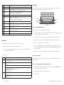
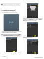
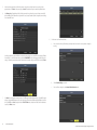
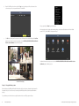
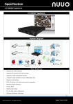
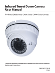
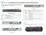
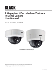
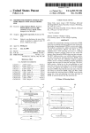
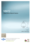
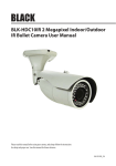
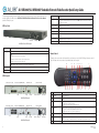
ALI-NVR3004P, ALI-NVR3008P Embedded Network Video Recorder Quick Setup Guide
This quick setup guide provides instructions to initially setup and use your new network video recorder. For additional information on the
extensive capabilities of your NVR, refer to the ALI-NVR3004P, ALI-NVR3008P Embedded Network Video Recorder User Manual
provided on CD with your system.
NVR Front Panel
LED Indicators|
IR Sensor
USB port
ALI-NVR3000P series NVR front panel
Item
Usage
LED indicators
Power: The POWER indicator turns green when NVR is powered on.
Item
Description
Camera (CH1 - CH4)
Network interface for IP cameras solely dedicated to the NVR. These cameras can only be accessed through the NVR. Each port
provides Power over Ethernet (PoE) power to the device connected to it. NOTE: Only the Observint line of 3SVision cameras can
be attached to these channels.
Monitor Out (HDMI, VGA)
HDMI and VGA connectors for a monitor.
AUDIO IN / OUT
Not functional. Included for future expansion.
ON / OFF switch
Switch for powering the NVR on and off
USB
This port can be used for a portable mobile HDD, flash drive, DVD burner, or mouse. An additional USB port is located on the
front panel.
RS-485 terminations
Not functional. Included for future expansion.
Power connector
Connector for standard 3-prong power cable.
Remote Control
Status:
1. The light is green when the IR remote control is enabled
The enter key on the remote control or the front panel has the same function as a mouse left click. The IR Range of the remote control is 10
meters. The buttons on the remote control correspond with the buttons on the front panel.
2. The light is red when the function of the composite keys (SHIFT) are used
3. The light is out when none of the above condition is met
17
Tx/Rx: TX/RX indicator flickers green when the network connection is functioning normally.
IR Receiver
Sensor for the remote control.
USB Interface
This port can be used for a USB mouse or USB flash memory devices.
13
12
10 8 6
4
11 9 7
5
1
NVR Backpanels
Camera (CH1 - CH4)
Monitor Out (HDMI, VGA)
Audio IN / OUT
ON / OFF switch
18
Item
LAN
USB
RS-485
Power connector
Fan outlet
ALI-NVR3004P backpanel
Camera (CH1 - CH4)
Monitor Out (HDMI, VGA)
USB
Audio IN / OUT
LAN
RS-485
ALI-NVR3008P backpanel
1
Name
Fan outlet
15
14
3
2
Function
1
POWER
Power on/off the device.
2
DEV
Enables/Disables Remote Control.
3
Alphanumeric Buttons
Switching to the corresponding channel in Live view or PTZ Control mode.
Inputting numbers and characters in Edit mode.
Switching between different channels in All-day Playback mode.
4
EDIT Button
Editing text fields. When editing text fields, it will also function as a Backspace button to delete the character in front of the
cursor. On checkbox fields, pressing the EDIT button will tick the checkbox.
In Playback mode, it can be used to generate video clips for backup.
ON / OFF switch
Power connector
16
5
A Button
Switching between input methods (upper and lowercase alphabet, symbols and numeric input).
6
REC Button
Entering the Manual Record settings menu.
In PTZ control settings, press the REC button and then you can call a PTZ preset by pressing Numeric button.
7
PLAY Button
Playback, for direct access to playback interface.
ALI-NVR30xxP_SQ
9/22/14
Item
Name
Function
8
INFO Button
Reserved.
9
VOIP button
Selecting all items on the list;
In live view or playback mode, it can be used to switch between main and spot video output
10
MENU button
Press the button will help you return to the Main menu (after successful login).
Press and hold the button for 5 seconds to turn off audible key beep.
11
PREV button
Switch between single screen and multi-screen mode.
12
DIRECTION/ENTER buttons
Navigating between different fields and items in menus.
In Playback mode, the UP and DOWN button are used to speed up and slow down recorded video.
The LEFT and RIGHT buttons select the next and previous day of recordings.
In LIVE view mode, these buttons can be used to cycle through channels.
13
PTZ button
Enter the PTZ Control mode.
14
ESC button
Return to the previous menu.
Press for Arming/disarming the device in Live View mode.
15
RESERVED
Reserved for future usage.
16
F1 button
Selecting all items on the list when used in a list field.
In PTZ Control mode, it will turn on/off PTZ light.
17
PTZ Control buttons
Buttons to adjust the iris, focus and zoom of a PTZ camera.
18
F2 button
Cycle through tab pages.
Soft keyboard
An on-screen QUERTY keyboard appears when you click in a field that accepts a text entry, such as a password or name. The keyboard is
shown in the following picture. Some control keys toggle their function when they are clicked.
Symbols /
Numbers
Uppercase /
Lowercase
Backspace
Escape / Exit
Soft keyboard
Step 1. Install the NVR and monitor
For the following steps, refer to the back panel photo above for the location of connectors.
1.
Place the NVR in a location that is secure, well ventilated and clean. The NVR should be positioned such that the back panel connectors
are accessible and the ventilation holes on the sides are not blocked.
2.
Install and setup your monitor in accordance with the instructions provided with the monitor. Do not power it on at this time.
Mouse Control
3.
Cable the HDMI or VGA connector to your monitor’s VGA or HDMI input. The HDMI interface provides the best performance.
A standard 3-button (left/right/scroll-wheel) USB mouse can also be used with this NVR. To use a USB mouse:
4.
Plug the mouse into the USB connector on the front or back of the NVR.
1.
Plug USB mouse into the either the front panel or backpanel USB connector of the NVR.
5.
2.
The mouse will be automatically detected. If the mouse is not detected, the mouse may not be compatible with the NVR. Please refer
to the recommended device list from your provider.
If you plan to access your NVR remotely, or configure your NVR to transmit alerts, email, etc. to external servers, plug a drop cable
from your local area network (LAN) into the RJ-45 LAN connector on the back of the NVR. (By default, the NVR automatically acquires
network settings using DHCP.)
6.
Connect the power cord to the power connector on the back panel of the NVR, and then into a UPS (preferred) or surge protector.
The operation of the mouse:
Action
Effect
Right click
Live view: Show menu.
Menu: Exit current menu to upper level menu.
Single click: Live view: Select channel and show the quick set menu.
Menu: Select and enter.
Double click: Live view: Switch between single-screen and multi-screen.
Left click
Click and drag: PTZ control: pan, tilt and zoom.
Tamper-proof, privacy mask and motion detection: Select target area.
Digital zoom-in: Drag and select target area.
Live view: Drag channel/time bar
Scroll wheel
2
Scroll up: Live view: Previous screen.
Menu: Previous item.
Step 2. Install cameras
Install your security cameras as needed to support your security requirements. Always refer to the documentation provided with the camera
for installation instructions.
Step 3. Connecting it together – initial system setup
1.
Plug the Ethernet cables from the cameras into the RJ-45 camera channel connectors on the back of the NVR. NOTE: Only Alibi or 3S
cameras will function through the camera channel connectors.
2.
Power on the NVR using the power on / off (I / O) switch on the back panel.
3.
Power on the monitor.
Scroll down: Live view: Next screen.
Menu: Next item.
www.Observint.com
© 2014 Observint Technologies, Inc. All rights reserved.
NOTE
4.
Some monitors have multiple inputs such including VGA ,HDMI, BNC, etc. If you are using this kind of monitor, configure your
monitor to display the input connected to your NVR (HDMI or VGA).
Power on your cameras.
1.1.1 Using the Wizard for basic configuration setup
1.
Power on your NVR. When the NVR is powered on, an Alibi logo splash screen appears within 2 minutes.
Observint strongly recommends that you change the default admin user password to improve the security of your surveillance system.
To change the admin password, check the New Admin Password box, then enter the new password in the New Password and
Confirm fields. Record your new password and save it in a secure place for reference later.
2.
After the initial Alibi loading window, the initial setup Wizard screen will appear. The Setup Wizard can assist you in making important
configuration settings in NVR. Click Next button on the Wizard window to open the Login window.
NOTE
The configuration settings presented in the setup Wizard can also be made and changed using the Menu system. See the ALI-NVR3004P,
ALI-NVR3008P Embedded Network Video Recorder User Manual provided on CD with your system for more information.
4.
3.
3
Click the Next button to open the date and time settings window.
Enter the admin password in the appropriate field. To do that, click inside the Admin Password field to open the virtual keyboard.
Click the appropriate icons to enter the password, then click the Enter icon. The default admin password is 1111.
www.Observint.com
© 2014 Observint Technologies. All rights reserved.
5.
In the date and time setup window, click the field you want to change, then use the drop-down list or setup aid to select the
appropriate values. Click Next to confirm your settings or Cancel to discard them and open the network setup Wizard window.
6.
In the Network setup Wizard window, click the field value you want to change, then use the pop-up aid to enter a new value. By
default, the NVR uses DHCP (Dynamic Host Configuration Processor) to acquire compatible (dynamic, changeable) network settings
from a network DHCP server.
8.
Use the camera record mode Wizard as follows:
a.
On the Cameras line at the top of the window, open the drop-down list and select the camera you want to configure for
recording.
b.
Click the Start Recording box to check it.
c.
Select one of the recording modes: either Normal or Motion Detection mode.
Generally, it is preferable to setup the NVR with a fixed network settings, if possible, to assure the NVR has an unchanging IP address
for remote logins. To enable fixed network settings, uncheck the Enable DHCP box, then edit the appropriate fields to change the
settings. Consult with your network administrator to determine the best network settings for your NVR. When finished, click Next.
7.
4
Click Next after you configured the network parameters. The HDD management Wizard window will open. If a new NVR is shipped
with a pre-configured HDD, nothing needs to be done in this window. If you installed an HDD or replaced the HDD, select (check the
box for) the HDD, then click Init to setup the disk for the NVR. NOTE: Init will erase all data from the disk. When the initialization is
complete, click Next to continue.
www.Observint.com
© 2014 Observint Technologies. All rights reserved.
d.
Repeat “a” and “b” above for each camera, and/or click Copy to copy the recording mode of the selected camera to other
cameras in the system. The screen presented below is for a 4-channel NVR.
In the pop-up window, click Menu. A login window will open.
In the Login window, select a User Name with administrative privileges, enter its password (the default user “admin” has the default
password of “1111”) , then click OK. The following window will open.
e.
Click OK when the recording mode for each camera is selected. The Wizard will close and the NVR will present the Live View
display. For more information about the Live View display, refer to the ALI-NVR3004P, ALI-NVR3008P Embedded Network
Video Recorder User Manual provided on CD with your system.
For additional information about using your system, refer to the ALI-NVR3004P, ALI-NVR3008P Embedded Network Video Recorder
User Manual provided on CD with your system.
4-channel Live View display
Step 4. Using the Menu system
After the initial setup of your NVR using the Wizard, the Menus interface enables you to refine your configuration settings and expand the
functionality of the system. To use most menus, the user must log into the NVR system, either locally or remotely, with administrative
privileges.
To open the Menu system from the Live View screen, right click anywhere in the screen. An OSD pop-up menu will open.
5
www.Observint.com
© 2014 Observint Technologies. All rights reserved.
Specifications
Model
ALI-NVR3004P
Number of Channels Supported
ALI-NVR3008P
4
8
Compression Format
H.264
Recording Performance
20 Mbps max
Remote Viewing Output Capacity
60 Mbps max
Recording Type
40 Mbps max
80 Mbps max
Continuous, Schedule, Motion Detection
Supported IP Camera Resolution
5MP / 3MP / 1080p / UXGA / 720p / VGA / 4CIF / DCIF / 2CIF / CIF / QCIF
Supported Playback Resolution
5MP / 3MP / 1080p / UXGA / 720p / VGA / 4CIF / DCIF / 2CIF / CIF / QCIF
Synchronous Playback
4-ch, 720P / 2-ch, 1080P / 1-ch, 5MP
Video Output
8-ch, 4CIF / 4-ch, 720P / 2-ch, 1080P / 1-ch, 5MP
VGA, HDMI
Video Output Formats
1 channel, resolution: 1920 × 1080P / 60 Hz, 1600 × 1200 / 60 Hz, 1280×1024 / 60 Hz,
Export Formats
Ethernet
.MP4
1x Gigabit RJ-45 self-adaptive Ethernet interface,
4 independent 10 /100 Mbps PoE Ethernet interfaces
USB
1x Gigabit RJ-45 self-adaptive Ethernet interface,
8 independent 10 /100 Mbps PoE Ethernet interfaces
2x USB 2.0
Hard Disk Drive (HDD) Interface
HDD Capacity
Operating System
2x SATA
2x HDDs max., up to 4TB capacity per HDD
Embedded Linux
Security
Password Protection
Protocols
IPv4, TCP/IP, UDP, HTTP, UPnP, RTSP / RTP / RTCP, SMTP, FTP, DHCP, NTP, DNS, ONVIF, HTTP multipart
Power Requirements
Power Consumption
110 ~ 240 Vac
3A
Weight
5.5 lbs. (without HDD)
Dimensions (h × w × d)
1.77" × 17.52" × 11.42"
Operating Temperature
14 °F ~ 131 °F (-10 °C ~ +55 °C)
Color / Material
Black, Gray
Material
Aluminum
Approvals
CE, FCC, RoHS
Remote Client System Requirements
Operating System
Web Browser
6
Microsoft Windows 2000, 2003, XP, Vista, 7, 8 (32-bit and 64-bit version) / Linux 2.6+ /
Apple MacOS X 10.5 (Intel x86 only), 10.6 and 10.7
Microsoft Internet Explorer 8.0, 9.0, and 10 (32-bit version), Mozilla Firefox 3.6, 13 and higher
Software Requirements
WebComponent plug-in installation
Mobile Client OS Platform
iOS, Android (Alibi Witness)
www.Observint.com
© 2014 Observint Technologies. All rights reserved.