1
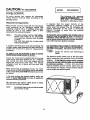
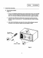
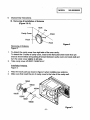
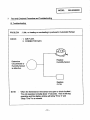
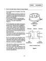
SEARS
DIVISION 20
SUPPLEMENTARY
BASIC FIELD MANUAL
FOR
MICROWAVE OVEN
MODEL 565.60586000
MARCH
2000
CAUTION
WARNINGPRECAUTIONS
SERVICING
TO SERVICE TECHNICIANS
TO BE OBSERVED
BEFORE AND DURING
TO AVOID POSSIBLE EXPOSURE
EXCESSIVE
MICROWAVE
TO
ENERGY
a. Do not operate or allow the oven to be operated with the door open.
b,
Make the following safety checks on all ovens to be serviced before activating the magnetron
or other microwave source, and make repairs as necessary ;
(1) Interlock operation, (2) proper door sensing, (3) seal and sealing surfaces (arcing,
and other damage), (4) damage to or loosening of hinges and latches, (5) evidence of
dropping or abuse.
c.
Before turning on microwave power for any service test or inspection within the microwave
generating compartments, check the magnetron, wave guide or transmission line and cavity
for proper alignment, integrity, and connections.
d. Any defective or misadjusted components in the interlock, monitor, door seal, and microwave
generation and transmission systems shall repaired, replaced or adjusted by procedures
described in this manual before the oven is released to the owner.
e. A microwave leakage check to vedfy compliance with the Federal
should be performed on each oven prior to release to the owner.
Performance
Standard
,
Never operate the magnetron
unless it is properly installed.
Proper operation of the
microwave
ovens requires that the magnetron
should be assembled
properly to the
wave guide and cavity.
•
Be sure that the magnetron gasket
whenever installing the Magnetron.
is properly
•
Routine
should be exercised
•
Untrained personnel should not attempt servicewithout
a thorough
procedures and safety information contained in this manual.
service
safety procedures
-i-
installed
around
the dome of the tube
at aft times.
review of the test
CAUTION For microwave
I MODEL
565.60586000
I
energy emission
On every service call, checks for microwave
energy emission must be made according
to the
following manner.
The followin,q U.S. standard
aUDlies to microwave ovens : 21
CFR 1030.
10, Performance
Standard for Microwave Ovens.
Measurement of energy emission
It requires
that the power density
of the
microwave
radiation emitted
by a microwave
ovens shall not exceed five (5) milliwatts per
square centimeter
at any point 5 centimeter
(about 2 inches) or more from the external
surface of the oven.
Measurement must be made with the microwave
oven operating
at its maximum
output and
containing a load of 275:1:15 milliliters of tap water
initially at 20°C + 5°C celsius (68°F :1: 9oF)
placed within the cavity at the center.
NOTE :
The water container must be a 600 milliliter
beaker and made of an electrically
nonconductive material such as glass
or plastic.
The cook tray mus._tbe in place when
measuring em=sslon.
All microwave ovens exceed n,q the emission level of
4mw/cm z must be reported to Dept. of Service for
microwave ovens andthe manufacture immediately
and the owner should be told not to use the microwave
oven untill it has been repaired completely.
A properly operating door and seal assembly will
normally resister small emissions but they must be no
greater than 4mwlcm 2 to allow for measurement
uncertainty.
If a microwave oven is found to operate with the
d.Qg.LqJ_=a3,_report
to Dept. of Service, the manufacture
and CDRH* immediately. Also tell the owner not to use
the oven.
* CDRH : Center for Device and Radiological
Health.
All repairs must be performed in such a manner
that mfcrowave energy emission is minimal.
Follow the instructions supplied with the survey
meter being used and perform an R.F. emission
test around the door front and edges and all
edges and vents of the outer case. The cabinet
(wrapper) must be in place and the oven fully
assembled.
When performing an emission survey, the meter
should be set on FAST RESPONSE and the movement
of the Survey Meter probe shall not exceed one (1) inch
per second.
In the area emitting the highest reading, switch the
meter to SLOW RESPONSE and take a reading for
minimum of three (3) seconds.
We recommend the pattern outline shown in below
when the door surface is surveyed.
NOTE:
Periodically check to be sure that the probe
tip is not worn or dirty.
-ii-
The interlock monitor switch acts as the finat safety
switch protecting the customer from microwave
radiation.
If the interlock monitor switch (_oerates
to blow the fuse with intedocks failed, you must replace
all interlock switches - primary and secondary
interlock switches and the monitor switch with new
ones because the contacts of those interlock switches
may be melted and welded together.
FORWARD
I MODEL565.60586000
I
This supplement covers the information about model 565.60586000
information to Basic Field Manual for Model 565.60509990.
Model
DIFFERENCES
Model 565.60586000
except the following
by adding the following
565.60586000
is the same as Model 565.60509990
specifications.
in the mechanical construction
A. The difference in features from Model 565.60509990.
Feature
Model
565.60586000
Humidity Sensor
Yes
Model
565.60509990
None
B. The difference in the main parts from Model 565.60509990.
Model
565.60586000
Description
Model
565.60509990
Cabinet
16707
16019
Bottom Plate
16702
16576
Detector
16310
None
16309
None
Circuit Diagram
16608
16648
Use & Care Manual
16579
16522
Fuse, 125V 20A
15628
16131
Fuse Holder
16703
16132
Space Partition (Blower)
16704
15905
Door Cover
16650
16519
Control Sheet, Display I Touch Key Board
16645
16518
Model No. & FCC Label
16709
16564
Control Frame
16708
16566
Control Base
16612
16568
Power & Control Circuit Board
16577
16516
Knob
16710
16570
Power & Control Circuit Board
16580
None
Part Base
16642
None
Assy
Duct, Detector
Assy
-1-
I MODEL
1.
565.60586000
Feature and Specification
Features
(A) The safety devices incorporated in this unit : (1) Fuse (Cartridge Type 20A).
(2) Primary interlock switch.
(3) Interlock monitor switch.
(4) Door sensing switch and relay 2.
(5) Choke system.
(6) Magnetron thermal protector opens at 122°(3 / closes at 105°C.
(B) Any one of 10 power levels ranging from minimum "P 0" up to maximum "P 100"
can be selected by turning "DIAL" clockwise.
(C) Cooking time and power output level can be displayed on window by digital readout.
(D) Three different cooking stages can be set. The oven remembers three cooking
stages from 1st stage to 3rd. This is made possible with the memory function of
microprocessor.
SPECIFICATIONS
Rated Power Consumption
...........................
Rated Microwave Output ...............................
Magnetron / Oscillating Frequency ................
Power Supply, Input Currant .........................
Tray ...............................................................
Door Sealing .................................................
Rectifier / Rectification ...................................
High Voltage Capacitor .................................
(including Resistor)
Cavity Lamp ..................................................
Timer .............................................................
Outer Dimensions ..........................................
Oven Cavity Dimensions ...............................
Cavity Volume ...............................................
Accessories
...................................................
1580W (measured after 15 mins. operation).
Maximum 960W (with 2 liters of water). '
1100W (IEC - 705 Method).
2M-247H(B) / 2450 + 50MHz.
120V + 10% AC 60Hz only.
13.6A (measured after 15 mins. operation).
Special heat-resistant Glass Turntable.
Choke System.
500mA, 9.5KV / Half-Wave Voltage Doubler.
1.03mfd, 2.1KV AC.
10 Meg. ohms, 1.5W.
120V, 20W.
Digital, up to 99 minutes 99 seconds.
233/10" (W) X 18-118" (D) X 14-1/4" (H).
16-5/s" (W) X 16" (D) X 11-31a"(H).
2.0 Cubic Feet.
Use and Care Manual and Cook Book,
Glass Turntable and Turn-table Roller Rest.
-2-
I
MODEL
2.
565.60586000
Overall Circuit Diagram
120V
N
60Hz
_GN
_L
FUSE
_ (2OA)
W
CAVIler
OPEN
TEMP.
: 167=_'C
FJJSE
CAVI1Y UGRT
w
THERMAL
PROTECTOR
OPEN :122_C
BLOWER MOTOR
W
HIGH _,iOLTAGETRANSFORMER
BK
............
l
GEAR MOTOR
BL
r
RELAY 2
I CONNECTOR
I Sl
RELAY 3
W
4._
_O
RL2 SIGNAL
CIRCUIT
CONNECTOR $IO2 t
SECONDARY
INTERLOCK
CONNECTOR
S20t
SW'ffCH)
1
I
MAGN_TRON
1_ ....
j
CAPACITOR
DIODE
1.03MFO
/_
2.1 I(VAC
RESISTOR
10MEG-OHM
1
I
STEP-DOYeN
TRANSFORMER
SENSOR
CIRCUIT
BOARD
CONNECTOR
Sl_
CONNECTOR
SI_
:
CONNECTOR
I
8.!I_. -- _ -- j
SECONDARYINTERLOCK
SWITCH
MADE
CONDWION
DOOR
•
PRIMARY
INTERLOCK
SWITCH
INTERLOCK
MON_OR
SW_CH
DOOR
SENSING
SWITCH
RELAY2
COM
COM
COM
COM
NO
NC
NO
NO
OPEN
DOORCLOSE
Caution
:
: The parts marked with I__.__carry more than 4KVDC
respective to ground.
-3-
high voltage with
MODEL
3.
565.60586000
Matrix Circuit for Touch Key Board
FPC Connector
($101)
& Matrix Circuit for Touch Key Board
L
FPC Connector - $101
"_UP
---m-- 2
---=,.-3
--P-4
_5
--m-- 6
---D.- 7
---P'- 8
---D_9
---=,-10
---=,.- 11
Matrix Circuit for Touch Key Board
FPC
CONNECTOR
S101
6
7
8
1
9
10
11
Po R
DEFROST
ON / OFF
DEQU T
KITCHEN
TIMER
ADD
MINUTE
5
_
CLEARSTOP
/
OPTION
-4-
CLOCK
MODEL
4.
565.60586000
Control Sheet, Display I Touch Key Board
Model
565.60586000
Model
: 565.60509990
Pa_ No
16645
Paff No
:
QuickTouch
Sensor
•
POI%'OnN
• Rm_NmmZZ
• POTATO
16518
FROZEN
ENTREE
ROUPI
BEVERAGE
POPCORN
PIZZA SLICE
CHICKEN
PIECES
POTATO
• PIZZASLRIE
•
FRF.SHV'_ETABUESOFT
• SOUP
•
FnESHV_EETABLEHAB• PLMEOFFOO0
•
FROZENV_TAIE
• BEVERA4R
• (_HIC'KI_N
PIECES
FROZEN
FRESH
VEGETABLE VEGETABLE
• RlaE
ADD MINUTE
FINE
DEFROST
KITCHEN
TIMER
ADD MINUTE
RICE
KITCHEN
TIMER
DEFROST
QUICK
DEFROST
FINE
QUICK
TURNTABLE
ON/OFF
CLOCK
TIME
POWER
CLOCK
OPTION
TIME
POWER
STOP
CLEAR
_.
"_
START •
| WEIGHT/T/4f
mJmlO_vo
START a
-5-
_
e;e
I
MODEL
.
Power Output Measurement
565.60586000
( 1 Liter Method )
The power output of the magnetron can be measured by performing a tap water
temperature rise test.
Equipment needed for test ;
One liter beaker.
One thermometer
Note
( digital recommended
).
: Check the line voltage during the test.
Low voltage will lower the magnetron output.
Make all temperature
test with accurate equipment.
(A)
Fill the 1 liter beaker with water ( 1000cc ).
(B)
Stir the water in the beaker with the thermometer
Initial water temperature = TI.
The initial water temperature
and record the temperature.
should be within 59°F( 15°C ) - 75°F(24oc).
(C)
Place the beaker on the center of the turntable.
(D)
Set for one minute and three seconds and operate the oven at high power.
Note : The additional three (3) seconds is to allow the magnetron to
begin generating power.
(E)
When the heating is finished, again stir the water with the thermometer
measure the temperature as T2.
(F)
Subtract TI from T2, this will give you the Temperature
(G)
The Microwave Power Output is within specifications if the Temperature
shown below :
Rise.
Temperature Rise
Line Voltage
Degrees F
Degrees C
120V
18.5 ~ 25.5
10.3 ~ 14.2
108V
Min 17.5
Min. 9.5
-6-
and
Rise is as
MODEL
6.
565.60586000
Disassembly Instructions
A.
Removing the Cabinet
(Figure 1)
.
The new UL Standard for Microwave Ovens requires that access to the potentiall
hazardous electrical voltages be restricted by some means. Kenmore, Source
565, use a new type of screw that cannot be removed by a regular screwdriver.
.
A special screw will prevent customer from removing the cabinet when they
attempt to repair or service the unit. This should reduce the number of injuries
reported.
,
Sears Service technicians can remove the screws with the following required
screwdriver, part number 22-16346 or bit, part number 22-16347.
Screwd river
(Part no. 16346)
Bit
(Part no. 16347)
Figure I
-7-
I
,
MODEL
565.60586000
Disassembly Instructions
B. Removing & Installation
(Figure 2 & 3)
of Antenna
Hook
Pin
Cavity Cover
Driver
Hook
Hook
Figure 2
Removing of Antenna
Figure 2.
1.
2.
To detach the cavity cover from right side of the oven cavity :
To detach the 3 hooks of cavity cover, insert a thin fiat-screw driver lower than pin
area as shown below and pushing it forward between cavity cover and cavity _Nall and
turn the cavity cover slightly to left side.
Take cavity cover off VERY CAREFULLY.
Installation Antenna
Figure 3.
1.
2.
Place the each parts as shown in figure 3 when installing new antenna.
Make sure that insert the pin of cavity cover to the hole of the cavity wall.
16543
J
16643
16544
16638
16545
16607
/
16639
Figure 3
-6-
I
I MODEL
7.
565.60586000
]
Test and Checkout Procedure and Troubleshooting
- Caution
-
DISCONNECT
THE POWER SUPPLY CORD FROM WALL OUTLET,
WHENEVER
REMOVING THE CABINET FROM UNIT, PROCEED
WITH THE TESTS AFTER THE HIGH VOLTAGE CAPACITOR
DISCHARGED
AND PRIMARY WINDING OF HIGH VOLTAGE
TRANSFORMER
DISCONNECTED
FROM POWER SUPPLY.
ALL OPERATION
CHECKS VVITH MICROWAVE LEAKAGE MUST
BE DONE WITH A WATER LOAD ( 1 CUP OF GLASS CONTAINER
)
IN THE OVEN.
A. Test Procedures
* P = Using Simpson #260
meter which is provided
with 9-voit battery.
COMPONENTS
MAGNETRON
* WIRE LEADS REMOVED
* a = NORMAL READING
* b = ABNORMAL READING
TEST PROCEDURES
*
1) Measure resistance across the
filament terminals of the
RESULTS
* a = Less than 1 ohm
Magnetron with Rxl ohm range.
2) Measure resistahce between
each filament terminal and earth
terminal (Chassis) with the
highest ohm range.
HIGH-VOLTAGE
TRANSFORMER
* a = Infinite ohms
1) Measure
resistance ( marked • )
with Rxl ohm range.
• Primary winding
• Filament winding
• Secondary winding
* a = 0.322 ohms
* a = Less than 1 ohms
* a = 64.8 ohms
2) Measure
resistance ( marked • )
with the highest ohm range.
• Primary winding to ground
• Filament winding to ground
HIGH-VOLTAGE
CAPACITOR *
( INCLUDING
RESISTOR )
NOTE
:
A MICROWAVE
MUST ALWAYS
1) Measure resistance with the
highest ohm range.
* a = Infinite ohms
* a = Infinite ohms
* a = momentarily middle
position and then
soon reach 10 Meg.
ohms .... * P
* b = continuity or
infinite ohms from
beginning.
ENERGY LEAKAGE TEST IN ACCORDANCE
WITH BULLETIN S - 375
BE PERFORMED WHEN THE UNIT IS SERVICED FOR ANY REASON.
-9-
MODEL
7.
565.60586000
Test and Checkout Procedure and Troubleshooting
A, Test Procedures
Humidity Sensor
The following test procedures indicate a check method as to whether the thermistors
in the sensor are open or short-circuited. Any characteristic relation between moisture
resistance value of the thermistors can not be checked because the amount of the
moisture can not be created as you need.
COMPONENTS
HUMIDITY
SENSOR
NOTE :
TEST PROCEDURES
Measure the resistance between
pins of connector $201 after
removing connector $201 :
Between Pins #1 and #3 of connector
$201 :
Between Pins #2 and #3 of connector.
$201 :
RESULTS
Normal reading
:
*
About 2.5K ohms
*
About 2.5K ohms
Note
• * The resistance value is measured by Simpson
#260 meter at 20°C room temperature.
But a
different meter will indicate different readings
because the value of resistance varies depending
on the temperature of the thermistors in the sensor
and these thermistors are heated by themselves
when the meter current passes through them.
Note
: If the thermistors in the sensor are open or shortcircuited, the symptoms will be as explained under
TROUBLESHOOTING on page 11.
A MICROWAVE ENERGY LEAKAGE TEST IN ACCORDANCE WITH BULLETIN S - 375
MUST ALWAYS BE PERFORMED WHEN THE UNIT IS SERVICED FOR ANY REASON.
-10-
I
I
I MODEL
7.
565.60586000
Test and Checkout Procedure and Troubleshooting
B. Troubleshooting
PROBLEM
: Little, no heating or overheating in produced in Automatic Reheat.
CHECK
: 1. AIR FLOW.
2. CONNECTOR
$201.
Replace
Humidity Sensor
Determine
Circuit Board or
Humidity Sensor
is defective.
Replace
P.C.B.
NOTE
When the thermistors in the sensor are open or short-circuited ;
The unit operates normally about 17 seconds. Then it will stop
operating and the display window will show "Error 2" and
UBeep Tone" for a moment.
-11 -
I
I MODEL
8.
565.60586000
I
How the Humidity Sensor Works for "Sensor Reheat"
The humidity sensor is located on top of the
oven cavity.
This sensor detects an amount of moisture as
it escapes from the food and the amount of
moisture is closely related to the doneness of
the food being reheated.
The sensor is composed of two thermistors.
One is sealed in a dry air compartment and
the other is in an open compartment.
(Figure 2).
The both thermistors are heated by themselves
at about 200oC when the oven is plugged in.
The thermistor in the dry air compartment is
cooled by the influence of air temperature
and the thermistor in the open compartment
is cooled by not only the air temperature but
also evaporation
of the moisture in the air
around the sensor.
If the sensor is in dry air, the both thermistors
in the sensor have the same resistance value,
regardless of the air temperature.
But if it is in moist air, the thermistor in the
open compartment will be cooled more by
evaporation of the moisture and the resistance
value will increase, compared with the
thermistor in the dry air compartment.
This develops a difference
between both
thermistors in resistance value.
The sensor sends that information
to the
microcomputer,
which calculates
and
automatically
adjusts the power lever and
remaining operating time.
-12-
,Outside of
Humidity Sensor
Figure
Thermistor
I
Moist Air
Thermistor
/
Open
Compartment
Dry Air
Compartment
Inside of Humidity Sensor
Figure 2