1
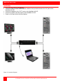
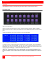
UltraMatrix AV HD 16x16 HDMI VIDEO MATRIX SWITCH INSTALLATION AND OPERATIONS MANUAL 10707 Stancliff Road Houston, Texas 77099 Phone (281) 933-7673 www.rose.com LIMITED WARRANTY Rose Electronics warrants the UltraMatrix AV HD to be in good working order for one year from the date of purchase from Rose Electronics or an authorized dealer. Should this product fail to be in good working order at any time during this one-year warranty period, Rose Electronics will, at its option, repair or replace the Unit as set forth below. Repair parts and replacement units will be either reconditioned or new. All replaced parts become the property of Rose Electronics. This limited warranty does not include service to repair damage to the Unit resulting from accident, disaster, abuse, or unauthorized modification of the Unit, including static discharge and power surges. Limited Warranty service may be obtained by delivering this unit during the one-year warranty period to Rose Electronics or an authorized repair center providing a proof of purchase date. If this Unit is delivered by mail, you agree to insure the Unit or assume the risk of loss or damage in transit, to prepay shipping charges to the warranty service location, and to use the original shipping container or its equivalent. You must call for a return authorization number first. Under no circumstances will a unit be accepted without a return authorization number. Contact an authorized repair center or Rose Electronics for further information. ALL EXPRESS AND IMPLIED WARRANTIES FOR THIS PRODUCT INCLUDING THE WARRANTIES OF MERCHANTABILITY AND FITNESS FOR A PARTICULAR PURPOSE, ARE LIMITED IN DURATION TO A PERIOD OF ONE YEAR FROM THE DATE OF PURCHASE, AND NO WARRANTIES, WHETHER EXPRESS OR IMPLIED, WILL APPLY AFTER THIS PERIOD. SOME STATES DO NOT ALLOW LIMITATIONS ON HOW LONG AN IMPLIED WARRANTY LASTS, SO THE ABOVE LIMITATION MAY NOT APPLY TO YOU. IF THIS PRODUCT IS NOT IN GOOD WORKING ORDER AS WARRANTED ABOVE, YOUR SOLE REMEDY SHALL BE REPLACEMENT OR REPAIR AS PROVIDED ABOVE. IN NO EVENT WILL ROSE ELECTRONICS BE LIABLE TO YOU FOR ANY DAMAGES INCLUDING ANY LOST PROFITS, LOST SAVINGS OR OTHER INCIDENTAL OR CONSEQUENTIAL DAMAGES ARISING OUT OF THE USE OF OR THE INABILITY TO USE SUCH PRODUCT, EVEN IF ROSE ELECTRONICS OR AN AUTHORIZED DEALER HAS BEEN ADVISED OF THE POSSIBILITY OF SUCH DAMAGES, OR FOR ANY CLAIM BY ANY OTHER PARTY. SOME STATES DO NOT ALLOW THE EXCLUSION OR LIMITATION OF INCIDENTAL OR CONSEQUENTIAL DAMAGES FOR CONSUMER PRODUCTS, SO THE ABOVE MAY NOT APPLY TO YOU. THIS WARRANTY GIVES YOU SPECIFIC LEGAL RIGHTS AND YOU MAY ALSO HAVE OTHER RIGHTS WHICH MAY VARY FROM STATE TO STATE. NOTE: This equipment has been tested and found to comply with the limits for a Class A digital device, pursuant to Part 15 of the FCC Rules. These limits are designed to provide reasonable protection against harmful interference when the equipment is operated in a commercial environment. This equipment generates, uses, and can radiate radio frequency energy and, if not installed and used in accordance with the instruction manual, may cause harmful interference to radio communications. Operation of this equipment in a residential area is likely to cause harmful interference in which case the user will be required to correct the interference at his own expense. IBM, AT, and PS/2 are trademarks of International Business Machines Corp. Microsoft and Microsoft Windows are registered trademarks of Microsoft Corp. Any other trademarks mentioned in this manual are acknowledged to be the property of the trademark owner. Copyright Rose Electronics 2013. All rights reserved. No part of this manual may be reproduced, stored in a retrieval system, or transcribed in any form or any means, electronic or mechanical, including photocopying and recording, without the prior written permission of Rose Electronics. Rose Electronics Part # MAN-UMA-16Hx16H Printed In the United States of America – 1.4 FCC/IC STATEMENTS, EU DECLARATION OF CONFORMITY Product UltraMatrix AV HD This equipment generates, uses and can radiate radio frequency energy and if not installed and used properly, that is in strict accordance with the manufacturer’s instructions may cause interference to radio communication. It has been tested and found to comply with the limits for a Class A digital device in accordance with the specifications of Part 15 of FCC rules, which are designed to provide reasonable protection against such interference when the equipment is operated in a commercial environment. Operation of this equipment in a residential area is likely to cause interference, in which case the user at his own expense will be required to take whatever measures may be necessary to correct the interference. Changes or modifications not expressly approved by the party responsible for compliance could void the user’s authority to operate the equipment. This digital apparatus does not exceed the Class A limits for radio noise emission from digital apparatus set out in the Radio Interference Regulation of Industry Canada. Operation is subject to the following two conditions: 1- This device may not cause harmful interference 2- This device must accept any interference received including interference that may cause undesired operation. Le présent appareil numérique n’émet pas de bruits radioélectriques dépassant les limites applicables aux appareils numériques de la classe A prescrites dans le Règlement sur le brouillage radioélectrique publié par Industrie Canada. CE Statement The product meets European Standard EMC: EN-55022:2006 Class A EN 61000-4-2:2001 EN 61000-4-3:2006 EN 61000-4-4:2004 EN 61000-4-5:2006 TABLE OF CONTENTS Contents Page # Introduction.............................................................................................................................................................................. 2 Disclaimer ............................................................................................................................................................................ 2 Features ............................................................................................................................................................................... 2 Specifications....................................................................................................................................................................... 3 Package contents ................................................................................................................................................................ 3 System Application .............................................................................................................................................................. 4 Installation ............................................................................................................................................................................... 5 Operation................................................................................................................................................................................. 6 Front Panel Control ............................................................................................................................................................. 6 Using the RoseControl Software ......................................................................................................................................... 8 Service Information ............................................................................................................................................................... 12 Maintenance and Repair ................................................................................................................................................... 12 Technical Support .............................................................................................................................................................. 12 Product Safety ....................................................................................................................................................................... 13 Appendices Page # Appendix A – Setting up the IP address on the UMA-16Hx16H/RCI.................................................................................... 14 Figures Page # Figure 1.System Application Overview ................................................................................................................................... 4 Figure 2. Connection Diagram ................................................................................................................................................ 5 Figure 3. Front Panel Buttons ................................................................................................................................................. 6 Figure 4. UltraMatrix AV HD Default Display .......................................................................................................................... 6 Figure 5. Main Menu ............................................................................................................................................................... 7 Figure 6. EDID Input Display.................................................................................................................................................. 7 Figure 7. RoseControl Configuration Screen .......................................................................................................................... 8 Figure 8. Main Routing Window .............................................................................................................................................. 9 Figure 9. Routing Window, Modified Connections ................................................................................................................ 10 Figure 10. Connecting the Network Cable ............................................................................................................................ 14 Figure 11. RoseControlIP Login screen ................................................................................................................................ 14 Figure 12. RoseControlIP Main Page ................................................................................................................................... 15 Figure 13. RoseControlIP Network Setting page .................................................................................................................. 15 INTRODUCTION Introduction Thank you for choosing Rose Electronics® UltraMatrix AV™ HD for your HDMI video switching requirements. The UltraMatrix AV HD is designed especially for control rooms, video presentations, security centers, video wall displays, and many other digital media applications. The ease of switching video sources makes the UltraMatrix AV HD a versatile and flexible addition to your system. Up to 16 video sources can be switched to any selected output port. The video switching can be controlled by the front panel, the RS232 input using a PC Windows based software, through a web browser (on some models), optional IR remote, or optional TCP/IP controller. The UltraMatrix AV HD supports HDTV resolutions of 480p, 720p, 1080i, and 1080p at distances up to 40 feet. Repetitive switching sequences can be recorded and saved in 1 of 50 macros for playback at any time. The access software makes switching the selected input to an output fast and easy. Just click on the input source and then the output destination and the video is instantly switched. Installation consists of two procedures: 1. Connecting the video sources and destination monitors to the unit 2. Installing the access software for controlling the UltraMatrix AV HD. Each video source is connected to one of the sixteen video in HDMI connectors using a HDMI to HDMI cable Disclaimer While every precaution has been taken in the preparation of this manual, the manufacturer assumes no responsibility for errors or omissions. Neither does the manufacturer assume any liability for damages resulting from the use of the information contained herein. The manufacturer reserves the right to change the specifications, functions, or circuitry of the product at any time without notice. The manufacturer cannot accept liability for damages due to misuse of the product or other circumstances outside the manufacturer’s control. The manufacturer will not be responsible for any loss, damage, or injury arising directly or indirectly from the use of this product. (See limited warranty) Features Switch one of sixteen video signals to multiple monitors Supports high definition video resolutions of 480p, 720p, 1080i and 1080p Delivers uncompressed digital video with zero signal loss Supports 7.1 Digital Surround Sound Audio HDCP and HDMI 4.1 compliant Click and switch intuitive software for instant video switching Optional Infrared remote control and TCP/IP control. Front panel buttons can be locked to prevent accidental changes 2 ULTRAMATRIX AV HD INSTALLATION AND OPERATIONS MANUAL Specifications Video HDTV Resolutions 480i, 480p, 720p, 1080i, 1080p Video Connectors (In / Out) HDMI Type A 19 pin Female TMDS Cable Length (In / Out) Up to 40 ft. Other Warranty Limited 1 Year Parts and Labor Control Panel, RS-232 (IR and TCP/IP optional) Power Internal 100-240 VAC Dimensions 19” W x 5.25” H (2U) x 7” D Weight 10 lbs. DVR 16X16 Approvals Power Supply Approvals FCC, CE, RoHS Compliant UL, CE, CSA, CEC, RoHS Environmental Operating Tempratures Operating Humidity Storage Temprature Storage Humidity 0 to +40° C (+32° to 104° F) 10% to 85% (Non-condensing) -20° to +60° (+20° to +140° F) 10% to 85% (Non-condensing) IMPORTANT: Each input and output can support up to 10mA/5VDC. Do not connect extenders that are powered by HDMI. Package contents 1304584334582_6.doc @ 51255 @ 2 @ 1 Your extender package contains the following items: UltraMatrix AV HD unit Serial Cable 1 country specific power cord Installation CD with RoseControl Software and this manual 3 ULTRAMATRIX AV HD INSTALLATION AND OPERATIONS MANUAL System Application Figure 1.System Application Overview Corporate or Educational Presentations Financial (Remote servers) Call Centers for Technical Support Industrial (Long-Range Workstation Isolation) Airport Installations (Air Traffic Control/Passenger Information) Medical (Remote viewing away from Sensitive/Magnetic Equipment) Recording (for Large Studios where Editing/Mixing Stations are Compact and/or Require Compete Silence) 4 ULTRAMATRIX AV HD INSTALLATION AND OPERATIONS MANUAL INSTALLATION Installation Turn off all input devices and displays. Connect the male to male HDMI extension cables to the input devices and to the “IN” ports on the UltraMatrix AV HD. Connect the displays to the “OUT” ports on the UltraMatrix AV HD. Connect the power cord and power-on the UltraMatrix AV HD. Power on the input devices and the displays. Figure 2. Connection Diagram 5 ULTRAMATRIX AV HD INSTALLATION AND OPERATIONS MANUAL OPERATION Operation The UltraMatrix AV HD can be controlled using either the front panel or the RoseControl software. Front Panel Control Figure 3. Front Panel Buttons NOTE: To lock the front panel buttons to avoid any accidental changes, press ESC + MENU + ENTER + SWITCH at the same time. The display will indicate that it is locked. Repeat the procedure to unlock the front panel. During normal operation, you will see a list of ports on the front panel display: Figure 4. UltraMatrix AV HD Default Display To assign an output to an input, press SWITCH. A blinking block cursor will appear. Use UP and DOWN to select the input that you would like to assign. Once the cursor is over the desired input port, press ENTER to enter editing mode. Press UP and DOWN to select the output port. Once you have selected an output, press ENTER to save the configuration. To escape from editing mode, press ESC. IMPORTANT: Because HDCP takes time to negotiate, wait 2 seconds when switching ports for the process to complete. Failure to do so may cause an HDCP error and the UltraMatrix AV HD may lock up. 6 ULTRAMATRIX AV HD INSTALLATION AND OPERATIONS MANUAL To view the menu, press MENU. There are 6 menu options available: Figure 5. Main Menu RS-232 Acknowledge - Sets the UltraMatrix AV HD to send a confirmation that an RS-232 command has been received. Send Update - Sets the UltraMatrix AV HD to send an RS-232 command back to the controller when the configuration is changed via the front panel or remote control (optional). Memory Save - Sets the UltraMatrix AV HD to save the configuration when powered off. Display Input Status - This displays the status of the inputs. If no input is present, the display will read NONE. This is the default view. Restore Factory Settings - Sets the UltraMatrix AV HD to the default factory configuration Manage EDID - Gives the option to learn the EDID of your display or choose a programmed EDID that is compatible with your monitor. Figure 6. EDID Input Display 7 ULTRAMATRIX AV HD INSTALLATION AND OPERATIONS MANUAL Using the RoseControl Software Find the Installation CD that came with your UltraMatrix AV HD unit. This CD has the RoseControl software that you will need in order to control the unit using a computer. Insert the CD into your CD-ROM. On the CD you should see: RoseControl_Installer.exe RoseControl Help File UltraMatrix AV HD Manual in PDF format Double click RoseControl_Installer.exe in order to initiate software installation. Click Install. After installation has completed, click CLOSE. In order to use the software, click on the START button>Programs>RoseControl. There you should see a help file, the RoseControl launcher as well as a shortcut to uninstall RoseControl. Click on RoseControl in order to launch the software. When the software starts you will see a screen like this (UltraMatrix AV DVI 16X16 Shown): Figure 7. RoseControl Configuration Screen 8 ULTRAMATRIX AV HD INSTALLATION AND OPERATIONS MANUAL Router Type: Select “Matrix DVI 16x16” Inputs/Outputs: Enter the number of Inputs/Outputs for your UltraMatrix AV HD (16x16). Com Port: Select the appropriate COM port that your computer is using to access the router. Router Time out: By default this is 0.2, meaning the computer acknowledges commands almost instantly. After you have entered the necessary information, click OK. This will now take you to the Main Routing Window where you can route the different HDMI connections. Figure 8. Main Routing Window On this screen you will notice the input buttons running down the left side while the output buttons run across the top. They are labeled 1 through 16. The Main Routing Window enables you to control the router’s connections by means of the crosspoint panel, the buttons, or with pre-recorded routing instructions called macros. 9 ULTRAMATRIX AV HD INSTALLATION AND OPERATIONS MANUAL Crosspoint Panel: This is probably the simplest way to route the connections. Simply click on the cross point itself. The input on the left will then be routed to the output above. Note: Inputs can be routed to several different outputs, but each output can only have a single input at any one time. So you can have several connections horizontally but not vertically. Figure 9. Routing Window, Modified Connections 10 ULTRAMATRIX AV HD INSTALLATION AND OPERATIONS MANUAL The Button Panel: These are the numbered buttons across the top and left sides. Click an output button on the top, and then click an input button on the left. Options for using the Button Panel: Output Options: To select multiple outputs next to each other, click on one output, then hold the shift key down and click the last output. When the input is clicked, it is routed to all selected outputs. To select multiple outputs individually, hold the control key down and click on any number of outputs. When the input is clicked, it is routed to all selected outputs. Input Options: To route an input to all the outputs at once, hold the control key down and click on an input. To leave the outputs selected after the route is made, hold the shift key down and click on an input. Macros: This section of the window is used to save and play back macros. Macros store a set sequence of routes. To record a macro: 1. Click on the Record button (last button shown). A blinking “recording” message below this button will be displayed to indicate that all routes are being recorded. 2. Select the desired crosspoints. There is no limit on the number of routes you may record. 3. If you click a macro button while in the record mode, the macro will be executed, and these routes will be added to the recording. This makes it possible to combine the routes of two or more macros into one bigger macro. 4. When finished, click the “Save Macro” button. You will be instructed to then click on one of the macro buttons. Doing this will save the recorded routes to that button. To cancel saving the macro, click the “Cancel Save” button. 5. To play back a macro, simply click on one of the 50 macro buttons. Use the scroll bar to bring any of these into view. 6. The macros are automatically saved in the current configuration file. They are also saved when you select the File/Save Configuration... menu. To save macros in a separate file for a special purpose, select the File/Save Macros...menu. 11 ULTRAMATRIX AV HD INSTALLATION AND OPERATIONS MANUAL SERVICE INFORMATION Service Information Maintenance and Repair This Unit does not contain any internal user-serviceable parts. In the event a Unit needs repair or maintenance, you must first obtain a Return Authorization (RA) number from Rose Electronics or an authorized repair center. This Return Authorization number must appear on the outside of the shipping container. See Limited Warranty for more information. When returning a Unit, it should be double-packed in the original container or equivalent, insured and shipped to: Rose Electronics Attn: RA__________ 10707 Stancliff Road Houston, Texas 77099 USA Technical Support If you are experiencing problems, or need assistance in setting up, configuring or operating your product, consult the appropriate sections of this manual. If, however, you require additional information or assistance, please contact the Rose Electronics Technical Support Department at: Phone: (281) 933-7673 E-Mail: [email protected] Web: www.rose.com Technical Support hours are from: 8:00 am to 6:00 pm CST (USA), Monday through Friday. Please report any malfunctions in the operation of this Unit or any discrepancies in this manual to the Rose Electronics Technical Support Department. 12 ULTRAMATRIX AV HD INSTALLATION AND OPERATIONS MANUAL SAFTEY Product Safety The UltraMatrix AV HD has been tested for conformance to safety regulations and requirements, and has been certified for international use. Like all electronic equipment, the UltraMatrix AV HD should be used with care. To protect yourself from possible injury and to minimize the risk of damage to the Unit, read and follow these safety instructions. Follow all instructions and warnings marked on this Unit. Except where explained in this manual, do not attempt to service this Unit yourself. Do not use this Unit near water. Assure that the placement of this Unit is on a stable surface or rack mounted. Provide proper ventilation and air circulation. Keep power cord and connection cables clear of obstructions that might cause damage to them. Use only power cords and connection cables designed for this Unit. Use only a grounded (three-wire) electrical outlet. Keep objects that might damage this Unit and liquids that may spill, clear from this Unit. Liquids and foreign objects might come in contact with voltage points that could create a risk of fire or electrical shock. Operate this Unit only when the cover is in place. Do not use liquid or aerosol cleaners to clean this Unit. Always unplug this Unit from its electrical outlet before cleaning. Unplug this Unit from the electrical outlet and refer servicing to a qualified service center if any of the following conditions occur: • The power cord or connection cables are damaged or frayed. • The Unit has been exposed to any liquids. • The Unit does not operate normally when all operating instructions have been followed. • The Unit has been dropped or the case has been damaged. • The Unit exhibits a distinct change in performance, indicating a need for service. 13 ULTRAMATRIX AV HD INSTALLATION AND OPERATIONS MANUAL APPENDICES Appendix A – Setting up the IP address on the UMA-16Hx16H/RCI The UMA-16Hx16H/RCI model has an embedded network access card. This is used to communicate with the unit over a network using a browser. Once the IP address has been set, the video switching can be accomplished through any web browser. The procedure to set the initial IP address for the unit is detailed below. The UMA-16Hx16H/RCI comes pre-configured with an IP address of 192.168.1.30 and IP network mask of 255.255.255.0. To connect to it through a network cable, the computer that is being used to configure the IP address of the unit should be on the same network. 1. Connect the unit’s RJ45 port to a computer configured with an Ethernet card and Window’s operating system (XP or Vista). Use a network cable to connect the computer to unit. Figure 10. Connecting the Network Cable 2. Access the control panel, network tab on the computer being used to configure the unit and change the existing IP address to 192.168.1.25 and the IP network mask to 255.255.255.0. This change creates a compatible standalone network between the unit and the computer. 3. From the computer used to configure the unit, start a web browser and enter the IP address 192.168.1.30 (unit’s default IP address) as the URL. 4. The unit will display the login screen shown below. Figure 11. RoseControlIP Login screen The default User ID is Admin and the default Password is Pass. The User ID and Password are case-sensitive. Enter the User ID and Password and click the button to proceed to the next page. 14 ULTRAMATRIX AV HD INSTALLATION AND OPERATIONS MANUAL 5. If the correct User ID and Password are entered, the unit will display the following page in the browser. Figure 12. RoseControlIP Main Page 6. Select the Network Setting tab on the top of the page. This will display the network settings for the unit in the Network Setting page. Figure 13. RoseControlIP Network Setting page 7. Enter the desired IP address and network mask for the unit, and click the Activate button to apply the entered settings. 8. The unit is now ready to be placed on the general network. Disconnect the unit from the computer and connect it directly to the network. Restore the previous IP address of the computer that was used to configure the unit, and connect it to the network. 15 ULTRAMATRIX AV HD INSTALLATION AND OPERATIONS MANUAL 10707 Stancliff Road Houston, Texas 77099 Phone: (281) 933-7673 WWW.ROSE.COM