1
Operator's
Manual
M
2-Cycle
WEEDWACKER® TRIMMER
Model No. 316.791160
o SAFETY
ASSEMBLY
OPERATION
MAINTENANCE
PARTS LIST
ESPANOL, R 11
CAUTION: Before using this
product, read this manual and
understand
all safety rules
and operating
instructions.
Sears Brands Management
Corporation,
Visit our website:
769-06251
POO
Hoffman
Estates, IL 60179 U.S.A.
www.craftsman.com
8/10
CALiFORNiA
PROPOSiTiON
65 WARNING
The purpose of safety symbols is to attract your attention to possible I
dangers. The safety symbols, and their explanations, deserve your careful
attention and understanding. The safety warnings do not by themselves
eliminate any danger. The instructions
or warnings they give are not_
substitutes for proper accident prevention measures.
J
THE ENGINE EXHAUST FROM THIS PRODUCT CONTAINS CHEMICALS
KNOWN TO THE STATE OF CALiFORNiA TO CAUSE CANCER, BIRTH
DEFECTS OR OTHER REPRODUCTIVE HARM.
SYMBOL
Attention is ALERT:
required inIndicates
order to avoid
personal
injury. May
SAFETY
danger,serious
warning
or caution.
be used in conjunction with other symbols or pictographs.
TABLE OF CONTENTS
Safety Rules .................................................
Warranty ....................................................
Know Your Unit ...............................................
2
4
4
Assembly Instructions ..........................................
Oil and Fuel Information ........................................
5
5
Starting/Stopping
Instructions
...................................
Operating Instructions
.........................................
Maintenance and Repair Instructions ..............................
Cleaning and Storage ..........................................
Troubleshooting Chart .........................................
Specifications
...............................................
Parts List ...................................................
Service Numbers .....................................
SPARK ARRESTOR
MEANING
6
6
7
8
9
10
22
Back Cover
NOTE:
vital to the operation or
injury to yourself or to others. Always follow the safety precautions
to obey
a safety
will result
in serious
fire,
electric
shockwarning
and personal
injury.
I_
_to
DANGER:
reduce the Failure
risk of
to
yourself and Failure
others. toAlways
safety can
precautions
WARNING:
obey afollow
safetythe
warning
result in to
injury
reduce the risk of fire, electric shock and personal injury.
property damage
or personal
to yourself
others.in
CAUTION:
Failure
to obey ainjury
safety
warning or
mayto result
Always follow the safety precautions to reduce the risk of fire,
electric shock and personal injury.
NOTE
NOTE: For users on U.S. Forest Land and in the states of California, Maine,
Oregon and Washington.
All U.S. Forest Land and the state of California
(Public Resources Codes 4442 and 4443), Oregon and Washington require, by
law that certain internal combustion engines operated on forest brush and/or
grass-covered areas be equipped with a spark arrestor, maintained in effective
working order, or the engine be constructed, equipped and maintained for the
prevention of fire. Check with your state or local authorities for regulations
pertaining to these requirements. Failure to follow these requirements could
subject you to liability or a fine. This unit is factory equipped with a spark
arrestor. If it requires replacement, ask your LOCAL SERVICE DEALER to install
the Accessory Part #753=06418 Muffler Assembly
Advises of information or instructions
maintenance of the equipment.
NOTE=
This Unit Can Use a Plug-In Power Start or Power Bit Start
Optional Accessory!
Please refer to the Plug-In Power Start or Power Bit Start operator's
manual for proper use of these features. (Plug-In Power Start
included / Power Bit Start sold separately! Please refer to page 8 of
this manual for more information about these accessories.)
Read the Operator's
Manual and follow
all warnings
and safety
instructions. Failure to do so can result in serious injury to the operator
and/or bystanders.
FOR QUESTIONS, CALL 1=800=4=MY=HOME®
All information, illustrations, and specifications in this manual are based on the
latest product information available at the time of printing. We reserve the right
to make changes at any time without notice.
• IMPORTANT
READ ALL INSTRUCTIONS
SAFETY INSTRUCTIONS
BEFORE OPERATING
followed. Please read these instructions before operating the unit
in order to ensure the safety of the operator and any bystanders.
ARNING: When using the unit, all safety rules must be
Please keep these instructions for later use.
•
Clear the area of children, bystanders and pets; keep them outside a 50-foot
(15 m) radius, at a minimum. Even then, they are still at risk from thrown
objects. Encourage bystanders to wear eye protection. If approached, stop
the unit immediately.
GENERAL SAFETY
Carefully inspect the area before starting the unit. Remove all debris such as
rocks, broken glass, nails, wire, string and other objects which may be thrown
or become entangled in the unit.
• Read the instructions carefully. Be familiar with the controls and proper use of
the unit.
Squeeze the throttle control and check that it returns automatically to the idle
position. Make all adjustments or repairs before using the unit.
[_.1
•
Keep these instructions. Refer to them often and use them to instruct other
users. If loaning this unit to others, also loan them these instructions.
Always stop the unit when operation is delayed or when walking from one
location to another.
Do not operate this unit when tired, ill or under the influence of alcohol, drugs
or medication.
Always hold the unit with both hands when operating. Keep a firm grip on
both handles or grips.
Children and teens under the age of 15 must not use the unit, except teens
guided by an adult.
Use the right tool. Only use this tool for its intended purpose.
Use the unit only in daylight or good artificial light.
Wear safety glasses or goggles that meet ANSI Z87.1 standards and are
marked as such. Wear ear/hearing protection when operating this unit. Wear a
face or dust mask if the operation is dusty.
Wear heavy long pants, boots, gloves and a long sleeve shirt. Do not wear
loose clothing, jewelry, short pants, sandals or go barefoot. Secure hair above
shoulder level.
Inspect the unit before use. Replace damaged parts. Make sure all fasteners
are in place and secure. Replace parts that are cracked, chipped or damaged
in any way. Do not operate the unit with loose or damaged parts.
All guards and safety attachments must be installed properly before operating
the unit.
Use only replacement parts or accessories recommended for this unit that are
distributed by Sears or a Craftsman outlet. Use of any replacement parts or
accessories purchased elsewhere may be hazardous, and will void the warranty.
Be aware of risk of injury to the head, hands and feet.
Do not force the unit. It will do the job better and with less likelihood of injury
at a rate for which it was designed.
• Do not overreach or use from unstable surfaces such as ladders, trees, steep
slopes, rooftops, etc. Always keep proper footing and balance.
Do not operate the unit faster than the speed needed to do the job. Do not
run the unit at high speed when not in use.
If the unit strikes or becomes entangled with a foreign object, stop the unit
immediately and check for damage. Do not operate before repairing damage.
Do not operate the unit with loose or damaged parts.
Keep unit clean of vegetation and other materials that may clog, gum or bind
moving parts, which may cause serious personal injury and or damage to the
unit.
Keep hands, face, and feet away from all moving parts. Do not touch or try to
stop any moving parts while they are in motion.
Allow the unit to cool before storing or transporting.
while transporting.
Be sure to secure the unit
Never douse or squirt the unit with water or any other liquid. Keep handles
dry, clean and free from debris. Clean after each use, see Cleaning and
Storage instructions.
• Store the unit in a dry place, secured or at a height to prevent unauthorized
use or damage. Keep out of the reach of children.
OIL AND FUEL SAFETY
m
_
explode
if ignited.
Take the
following
precautions:
ARNING:
Gasoline
is highly
flammable
and its vapors can
• Avoid accidental starting. Be in the starting position whenever pulling the
starter rope. The operator and unit must be in a stable position while starting.
Refer to Starting/Stopping Instructions.
Do not touch the engine, gear housing or muffler. These parts get extremely
hot from operation, even after the unit is turned off.
This unit has a clutch. The unit attachment remains stationary when the engine
is idling. If it does not, take the unit to a Sears or other qualified service dealer
for an adjustment.
Turn the engine to off and disconnect the spark plug for maintenance or repair.
TRIMMER SAFETY
i
• Store fuel only in containers specifically designed and approved for the
storage of such materials.
• Always stop the engine and allow it to cool before filling the fuel tank. Never
remove the fuel tank cap or add fuel when the engine is hot. Never operate the
unit without the fuel cap securely in place.
• Always mix or add fuel in a clean, well-ventilated outdoor area where there are
no sparks or flames. Do not smoke.
• Never Operate the unit without the fuel cap securely in place.
The trimmer attachment shield must always be in place while operating the
unit. Do not operate unit without both trimming lines extended, and the proper
line installed. Do not extend the trimming line beyond the length of the shield.
Avoid creating a source of ignition for spilled fuel. Wipe up any spilled fuel
from the unit immediately before starting the unbit. Move the unit at least 30
fett (9.1 m) from the fueling source and site before starting the unit. Do not
smoke.
Adjust the D-handle that provides the best possible grip.
Be sure the trimmer attachment is not in contact with anything before starting
the unit.
Use only 0.095 in. (2.41 mm) diameter replacement line. Never use metalreinforced line, wire, chain or rope. These can break off and become
dangerous projectiles.
• Never start or run the unit inside a closed room or building. Breathing exhaust
fumes can be fatal. Operate this unit only in a well-ventilated outdoor area.
• Check the unit for fuel leaks.
Keep unit clean of vegetation and other materials. They may become lodged
between the trimmer attachment and shield.
Loosen the fuel tank cap slowly to relieve any pressure in the tank.
• Never store the unit with fuel in the tank, inside a building where fumes may
reach an open flame (pilot lights, etc.) or sparks (switches, electrical motors, etc.).
Keep hands, face, and feet away from all moving parts. Do not touch or try to
stop the trimmer attachment when it rotates.
To reduce fire hazard, replace a faulty muffler and spark arrestor. Keep the
engine and muffler free from grass, leaves, excessive grease or carbon build up.
,, SAFETY
SAVETHESEINSTRUCTIONS
& INTERNATIONAL
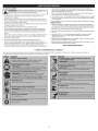
This operator's manual describes safety and international symbols and pictographs
complete safety, assembly, operating and maintenance and repair information.
SYMBOL
SYMBOLS
,,
that may appear on this product.
SYMBOL
MEANING
W/
:::::_:ev!
I
|
i
3
Read the operator's
manual for
CRAFTSMAN
2 YEAR
FULL
WARRANTY
FOR 2 YEARS from the date of purchase, this product is warranted against any defects in material or workmanship.
free replacement if repair is unavailable.
For warranty coverage details to obtain repair or replacement,
visit the web site: www.craftsman.com
This warranty
•
covers
ONLY defects
in material
and workmanship.
Warranty
coverage
Defective product will receive free repair or
does NOT include:
Expendable items that can wear out from normal use within the warranty period, such as cutting line, filters or spark plugs.
Product damage resulting from user attempts at product modification or repair or caused by product accessories.
Repairs necessary because of accident or failure to operate or maintain the product according to all supplied instructions.
Preventive maintenance, or repairs necessary due to improper fuel mixture, contaminated or stale fuel.
This warranty is void if this product is ever used while providing commercial
services or if rented to another person.
This warranty gives you specific legal rights, and you may also have other rights, which vary from state to state.
Sears Brands Management
Corporation,
Hoffman Estates, IL 60179
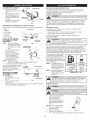
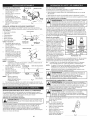
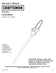
APPLICATIONS
As a trimmer:
•
Cutting
grass and light weeds
Muffler
Edging
Decorative
Other
optional
Spark Plug
trimming
accessories
around
trees,
fences,
etc.
may be used with this unit.
Starter Rope
Grip
Shaft
Grip
Air Filter
Cover
On/Off
D-Handle
Controm
Fuel Cap
Convertible
TM
Coupler
Throttle
Controm
Shaft Housing
Cutting
Hassle Free ®
Cutting Head
Head Shield
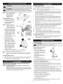
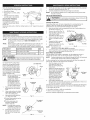
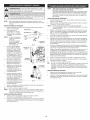
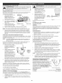
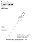
ADJUSTING THE D=HANDLE
1.
Loosen the bolt on the
handle just enough to move it
(Fig. 1).
2.
3.
Shaft Grip
OIL AND FUEL MIXING
Shaft Housing
While holding the unit in the
operating position (Fig. 9),
move the D-handle to the
location that provides the
best grip.
m
_
D-Handle
Tighten the bolt until the Dhandle is secure (Fig. 1).
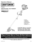
OPERATING THE CONVERTIBLE
The Convertible
TM
TM
COUPLER
SYSTEM
If choosing to use a blended fuel, or its use is unavoidable,
recommended precautions:
Always use the fresh fuel mix explained in the operator's
Primary Hole
oes w
_
_,
_---_¢"-'/_
NOTE:
To make installing or
removing the attachment
easier, place the unit on
the ground or on a work
bench.
1.
Turn knob counterclockwise
to loosen (Fig. 3).
2.
While firmly holding the
attachment, push it straight
into the Convertible TM
coupler until the release
button snaps firmly into the
primary hole (Fig. 2).
CAUTION:
Upper Shaft
Housing
For proper engine operation and maximum
reliability, pay strict attention to the oil and fuel mixing instructions
on the 2-cycle oil container. Using improperly mixed fuel can
severely damage the engine.
Lower Shaft
Housing
Fig. 2
The bottle of 2-cycle oil that came with the unit contains a fuel additive that
will help inhibit corrosion and minimize the formation of gum deposits.
Always use a good 2-cycle oil designed for air-cooled engines along with a
fuel additive, such as STA-BIL® Gas Stabilizer or an equivalent. Add 0.8 oz.
(23 ml) of fuel additive per gallon of fuel according to the instructions on the
container. NEVER add fuel additives directly to the unit's fuel tank.
90° Edging Hole
(Trimmer Only)
Thoroughly mix the proper ratio of
2-cycle engine oil with unleaded
gasoline in a separate fuel can. Use
a 40:1 fuel/oil ratio. Do not mix
them directly in the engine fuel tank.
See the table below for specific gas
and oil mixing ratios.
_Knob
Fig. 3
Aligning the release
button with the guide recess will help installation
Turn the knob clockwise to tighten (Fig. 3).
For decorative edging with the line
head trimmer attachment or other
attachment, lock the release
button of the attachment into the
90 ° hole (Fig. 3).
C°nvertibleTM
Coupler .,
(Fig. 4).
NOTE:
Release Button
/
NOTE:
REMOVING THE TRIMMER
ATTACHMENT OR OTHER
ATTACHMENT
1.
Turn the knob
2.
counterclockwise
to loosen
(Fig. 3).
Press and hold the release
manual
Using Fuel Additives
NOTE:
3.
follow
. Always agitate the fuel mix before fueling the unit
. Drain the tank and run the engine dry before storing the unit
., Hedge Trimmer
INSTALLING THE TRIMMER
ATTACHMENT OR OTHER
ATTACHMENT
10%
ethanol will
likelybeen
damage
thisthat
engine
and void thegreater
warranty.
ARNING:
It has
proven
fuel containing
than
Today's fuels are often a blend of gasoline and oxygenates such as ethanol,
methanol, or MTBE (ether). Alcohol-blended fuel absorbs water. As little as
1% water in the fuel can make fuel and oil separate. It forms acids when
stored. When using alcohol-blended fuel, use fresh fuel (less than 30 days
old).
Using Blended Fuels
coupler system enables the use of these optional attachments.
., Edger
* Turbo Blower
" Cultivator
Brushcutter
INSTRUCTIONS
Old and/or improperly mixed fuel are the main reasons for the unit not
running properly. Be sure to use fresh, clean unleaded fuel. Follow the
instructions carefully for the proper fuel/oil mixture.
Definition of Blended Fuels
Guide Recess
_
Fig. 4
One gallon (3.8 liters) of
unleaded gasoline mixed
with one 3.2 oz. (95 ml)
bottle of 2-cycle oil makes
a 40:1 fuel/oil ratio.
Dispose of the old fuel/oil
mix in accordance to
Federal, State and Local
regulations.
UNLEADED GAS
2 CYCLE OIL
f GALLON US
(3.8 LITERS)
f LITER
MiXiNG
3.2 FL. OZ.
(95 ml)
25 ml
RATIO
_40il
may explode. Always stop the engine and allow it to cool before
filling the fuel tank. Do not smoke while filling the tank. Keep
WARNING:
Gasoline is extremely flammable. Ignited vapors
sparks and open flames at a distance from the area.
button (Fig. 4).
3.
While firmly holding the upper shaft housing, pull the attachment
out of the Convertible TM coupler (Fig. 2).
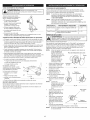
FUELING THE UNIT
straight
_
spray.
Never operate
the fuel
unit cap
without
capinjury
securely
place.
WARNING:
Remove
slowlythetofuel
avoid
from infuel
_
up any spilled fuel immediately. Avoid creating a source of ignition for
WARNING:
a clean,
well
outdoor area. Wipe
spilt fuel. Do notAdd
startfuel
the inengine
until
fuelventilated
vapors dissipate.
1.
Turn unit on its side, with the
fuel cap facing up, and
remove the fuel cap.
2.
Place the gas container's
spout into the fill hole on the
fuel tank and fill the tank.
(Fig. 5)
NOTE: Do not overfill the tank.
5
3.
Wipe up any gasoline that
may have spilled.
4.
5.
Reinstall the fuel cap.
Fig. 5
Move the unit at least 30 ft.
(9.1 m) from the fueling source and site before starting the engine.
i
m
A
I WARNIN6:
_
Operate this unit only in a well-ventilated outdoor area.
Carbon monox de exhaust fumes can be ethan
a conf ned area.
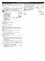
STARTING iNSTRUCTiONS
1.
2.
Mix gas with oil. See Oil and Fuel Mixing Instructions.
Fill the fuel tank with the fuel/oil mixture.
NOTE:
starting position when pulling the starter rope (Fig. 8). To avoid serious
I WARNING:
Avoid
starting.
Makeposition
sure to while
be in the
injury, the operator
and accidental
unit must be
in a stable
starting. !
I _
NOTE:
This unit has the IncrediPull TM starting system,
which significantly
reduces the effort
required to pull the
starter rope.
3.
Fully press and release the primer bulb 10 times, slowly. Some amount of
fuel should be visible in the primer bulb and fuel lines (Fig. 7). If fuel can not
be seen in the bulb, press and release the bulb as many times as it takes
until fuel can be seen in it.
off (o) _._
4.
Flip the choke lever clockwise
5.
Crouch in the starting position (Fig. 8). Do not squeeze the throttle. Place
the Plug-In Power Start or Power Bit Start into the back of the unit.
Refer to the Operation section of the Plug-In Power Start or Power Bit
Start operator's manual.
6.
Press and hold the ON (I) button of the Plug-in Power Start or Power Bit
Start equipped drill in intervals no longer than 4 seconds each until the
unit starts.
7.
Wait and allow the unit to idle for 5 - 10 seconds. If the unit stops running
during this time, squeeze the throttle control, then press and hold the ON
(I) button of the Plug-in Power Start or Power Bit Start equipped drill in
intervals no longer than 4 seconds each until the unit starts.
8.
9.
Remove the Plug-In Power Start or drill from the unit.
Squeeze and hold the throttle control for 30 to 60 seconds to allow the
unit to warm up.
STARTING INSTRUCTIONS
1.
Mix fuel with oil. See Oil and
Fuel Mixing Instructions.
2.
Fill the fuel tank with fresh,
clean fuel mix. Refer to
Fueling the Unit.
NOTE:
There is no need to turn
the unit on. The On/Off
Control is in the ON (I)
position at all times (Fig. 6).
3.
Fully press and release the
primer bulb 10 times, slowly.
Some amount of fuel should
be visible in the primer bulb
and fuel lines (Fig. 7). If fuel
can not be seen in the bulb,
press and release the bulb
until fuel is visible.
4.
Flip the choke lever clockwise
until it clicks (Fig. 7).
5.
Crouch in the starting
position (Fig. 8). Do not
squeeze the throttle. Pull the
starter rope in a controlled
motion until the unit starts.
6.
Wait and allow the unit to idle
for 5 - 10 seconds. If the unit
Control
Fig. 6
Choke
LeverJ
IF...
IF...
Primer
Bulb
1.
2.
Fig. 7
Squeeze and hold the throttle
control for 30 to 60 seconds to allow
IF...
The engine does not start, go back
NOTE:
If the unit is hot and fails to start
squeeze the throttle control and
starts.
STOPPING
1.
2.
INSTRUCTIONS
Release the throttle control and allow the engine to cool down by idling.
Press and hold the On/Off Control in the OFF (O) position until the
engine comes to a complete stop (Fig. 6).
Starting
Position
HOLDING
m
_[_
Fig. 8
the unit to warm up.
to step 3.
within 3 pulls of the starter rope,
pull the starter rope until the unit
INSTRUCTIONS
Release the throttle control and allow the engine to cool down by idling.
Press and hold the On/Off Control switch in the OFF (O) position until
the unit comes to a complete stop (Fig. 6).
THE UNiT
to reduce
the risk
of injury
this and
unit.body protection
ARNING:
Always
wearwhen
eye, operating
hearing, foot
Before operating the unit, stand in
the operating position (Fig. 9).
Check for the following:
• The operator is wearing eye
protection and proper clothing
With a slightly-bent right arm,
the operator's hand is holding
the shaft grip
The operator's left arm is
straight, the left hand holding
the D-handle
• The unit is at waist level
Fig. 9
The cutting head is parallel to
the ground and easily contacts the grass without the need to bend over
TiPS FOR BEST TRIMMING
•
HOW TO START THE UNiT USING THE PLUG-IN
POWER BiT START ACCESSORY
NOTE-
until it clicks (Fig. 7).
The engine does not start, go back to step 3.
The engine fails to start after a few attempts, squeeze the throttle
control, then press and hold the Plug-In Power Start or drill ON (I)
button in intervals no longer than 4 seconds each until the unit starts.
STOPPING
stops running during this
time, squeeze the throttle
control and pull the starter
rope in a controlled motion
until the unit starts.
7.
There is no need to turn the unit on. The On/Off Control is in the
ON (I) position at all times (Fig. 6).
POWER START OR
This unit can use a Plug-in Power Start or Power Bit Start
optional accessory!
Please refer to the Plug-In Power Start or Power Bit Start operator's
manual for proper use of this feature. (Plug-In Power Start included /
Power Bit Start sold separately. Please refer to page 8 of this manual
for more information about these accessories.)
RESULTS
Keep the cutting head parallel to the ground.
Do not force the cutting head. Allow the tip of the line to do the cutting,
especially along walls. Cutting with more than the tip will reduce cutting
efficiency and may overload the engine.
Cut grass over 8 inches (200 mm) by working from top to bottom in small
increments to avoid premature line wear or engine drag.
Cut from right to left whenever possible. Cutting to the left improves the
unit's cutting efficiency. Clippings are thrown away from the operator.
Slowly move the unit into and out of the cutting area at the desired height.
Move either in a forward-backward
or side-to-side motion. Cutting shorter
lengths produces the best results.
Trim only when grass and weeds are dry.
The life of the cutting line is dependent
Following the trimming techniques
What vegetation
upon:
is being cut
Where vegetation is cut
For example, the line will wear faster when trimming
wall as opposed to trimming around a tree.
against a foundation
]
Some
linebreakage
willoccur
from:
• Entanglement
with
foreign
matter
• Normal
linefatigue
Attempting
tocutthick,
stalky
weeds
Forcing
thelineintoobjects
such
aswalls
orfence
posts
DECORATIVE
5.
6.
Correctly installed line will be the same length on both sides.
NOTE:
Do not rest the Hassle-Free TM Cutting Head on the ground while
the unit is running.
AIR FILTER MAINTENANCE
--
TRiMMiNG
Decorative trimming is
accomplished by removing all
vegetation around trees, posts,
fences, etc.
Fig. 10
_
andARNING:
allow it to coolTo
before
or maintaining
avoid cleaning
serious personal
injury,it.
always turn the unit off
Cleaning
the Air Filter
Clean the air filter every 10 hours of operation. It is an important item to
maintain. Failure to maintain the air filter properly can result in poor
performance or can cause permanent damage to the engine.
Rotate the whole unit so that the cutting head is at a 30 ° angle to the ground
(Fig. 10).
1.
MAINTENANCE
FREQUENCY
MAINTENANCE
REQUIRED
Every 10 hours
Clean and re-oil air filter
p. 7
Every 25 hours
Check spark plug condition and gap
p. 8
for Hassle-Free TM Cutting Head
Always use Craftsman@ HassleFree TM XTRA QUIET Spiral Line.
Choose the line size best suited
for the job at hand. Red colored
line is designed for cutting grass
and small weeds. Black colored
The idle speed of the engine is
between the air filter cover and
NOTE:
Careless adjustments
service dealer should
i
1.
Line Glide Plate
Release the throttle trigger and
let the engine idle. If the engine
stops, insert a small phillips
screwdriver into the idle
Idle Speed
Screw
adjustment screw (Fig. 15).
Turn the idle speed screw
clockwise 1/8 of a turn at a
time (as needed) until the
engine idles smoothly.
Fig. 15
3.
If the engine appears to be
idling too fast, turn the idle speed screw counterclockwise
1/8 of a turn
at a time (as needed), to reduce idle speed.
Checking the fuel mixture, cleaning the air filter and adjusting the idle speed
should solve most engine problems. If not and all of the following are true:
the engine will not idle
Fig. 11
Positioning
Tunnel
the engine hesitates or stalls on acceleration
there is a loss of engine power
Have the carburetor adjusted by an authorized
Fig. 12
Line
against
"B" when using lines with
diameters smaller than
medium (red)line
the hub
NOTE:
4.
Start the engine and run for
one minute to warm up.
Refer to Starting/Stopping
Instructions.
2.
"A" when using medium (red) or
large (black)line, or
Line glide plate must be
reinstalled in cutting head
before inserting new line.
Insert both ends of your line
through the proper holes in
the side of the cutting head
(Fig. 12).
adjustable. An idle adjustment screw is
the engine starter housing (Fig. 15).
can seriously damage the unit. An authorized
make carburetor adjustments.
If, after checking the fuel mixture and cleaning the air filter, the engine still
will not idle, adjust the idle speed screw as follows:
Clean entire surface of cutting
head. Note positions "A" and
"B" on the cutting head.
Reinstall line glide plate (Fig.
11). Align arrow with:
Squeeze the filter to spread
and remove excess oil.
Replace the air filter into the
Lock Tab
air filter cover (Fig. 14).
Fig. 14
NOTE:
Operating the unit
without the air filter WILL VOID the warranty.
7.
Close the air filter cover by swinging it to the left and then pressing it
down until the lock tab snaps into place (Fig. 14).
IDLE SPEED ADJUSTMENT
NOTE:
3.
Before inserting new line
into the holes in the
cutting head,identify the
proper holes. Follow
directions as shown on
the line glide plate. Do
Not attempt to remove
the cutting head from the
unit when replacing line.
Remove the old line and line
glide plate from the cutting
head.
Air Filter Cover
6.
line is designed for cutting larger
weeds and light brush.
2.
Wash the filter in detergent and
water. Rinse the filter
thoroughly and allow it to dry.
Apply enough clean SAE 30
motor oil to lightly coat the
filter.
5.
LINE REPLACEMENT
1.
Remove the air filter (Fig. 14).
3.
4.
SEE
rope. These can Never
break use
off and
become dangerous
projectiles.
WARNING:
metal-reinforced
line, wire,
chain or
Open the air filter cover by pressing the lock tab in and pulling out on
the air filter cover (Fig. 14).
2.
SCHEDULE
Perform these required maintenance procedures at the frequency stated in
the table. These procedures should also be a part of any seasonal tune-up.
NOTE:
Some maintenance procedures may require special tools or skills.
For these types of repairs call 1-800-4-MY-HOME®
for more
information.
NOTE:
Please read the California/EPA statement that came with the unit
for a complete listing of terms and coverage for the emissions
control devices such as the spark arrestor, muffler, carburetor, etc
--
Pull the line and make sure the line is against the hub and is fully extended
through the positioning tunnels (Fig. 13).
Fig. 13
7
service dealer.
i
REPLACING
THE SPARK PLUG
PLUG-IN
Use a Champion RDJ7J or replacement part #753-06193 spark plug (or
equivalent). Remove the plug after every 25 hours of operation and check its
condition.
1.
Stop the engine and allow it to cool. Grasp the plug boot firmly and pull
it from the spark plug.
2.
Clean around the spark plug. Remove the spark plug from the cylinder
head by turning a 5/8-inch socket counterclockwise.
-_L_
3.
4.
electrodes.
Grit inDo
thenot
engine
cylinder.
ARNING:
sand could
blast, damage
scrape orthe
clean
spark plug
Replace a cracked, fouled or
dirty spark plug. Set the air
gap at 0.025 in. {0.635 rnrn)
using a feeler gauge (Fig. 16).
Install a correctly-gapped
spark plug in the cylinder
head. Tighten by turning the
5/8-inch socket clockwise
until snug. If using a torque
wrench, torque to:
item
0.025 in.
(0.635 ram)
t
Fig. 16
Reattach the plug boot.
TRANSPORTING
• Allow the engine to cool before transporting.
Drain fuel from unit.
• Tighten fuel cap before transporting.
• Secure the unit while transporting.
CLEANING
Use a small brush to clean off the outside of the unit. Do not use strong
detergents. Household cleaners that contain aromatic oils such as pine and
lemon, and solvents such as kerosene, can damage plastic housing or handle.
Wipe off any moisture with a soft cloth.
STORAGE
Never store a fueled unit where fumes may reach an open flame or spark.
Allow the engine to cool before storing.
Store the unit locked up to prevent unauthorized
use or damage.
Store the unit in a dry, well-ventilated area.
Store the unit out of the reach of children.
LONG TERM STORAGE
If planning on storing the unit for an extended time, use the following storage
procedure:
1.
2.
3.
Carefully drain the fuel tank by running the unit dry or remove fuel cap
and tip the motor housing over and drain oil/gas fuel into a container
with the same 2-cycle fuel mixture. Do not use fuel that has been stored
for more than 30 days.
Start the engine and allow it to run until it stalls. This ensures that all
fuel has been drained from the carburetor.
Allow the engine to cool. Remove the spark plug and put 3 - 5 drops of
any high quality motor oil or 2-cycle oil into the cylinder. Pull the starter
rope slowly to distribute the oil. Reinstall the spark plug.
NOTE:
4.
Power
No.
316.85951
316.85952
110-120 in.olb. (12.3-13.5
Nora). Do not over=tighten.
5.
i
Remove the spark plug and drain all of the oil from the cylinder before
attempting to start the trimmer after storage.
Thoroughly clean the unit and inspect it for any loose or damaged
parts. Repair or replace damaged parts and tighten loose screws, nuts
or bolts. The unit is ready for storage.
POWER START AND POWER BiT START FEATURES
This unit can be started with an optional
Plug-In Power Start or Power Bit Start
(Plug-In Power Start included / Power Bit
Start sold separately). If choosing to start
the unit using one of these features or
have questions, please contact your local
Craftsman retailer or call 1-800=4-MY=
HOME@ for more information and
purchasing. You may also go to
www.craftsman.com.
Start
Feature
Description
.....................................
........................................
Plug-In Power Start
Power Bit Start
PROBLEM
SOLUTION
Empty
fueltank
Fillfueltankwithproperly
mixed
fuel
OldFuel
Drain
fueltankandaddfresh
fuelmixture
Airfilterisplugged
Replace
orclean
theairfilter
OldFuel
Drain
gastankandaddfresh
fuel
f
I
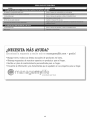
%u,([ find the answeI
° Find this
¢
¢
_'
and moze on ma_agemy[ife°com
and a[[ your other
product
manuals
online,
- for free°
!
i@
Get answers from our team of home experts.
° Get a personalized
maintenance
plan for your home.
° Find information
and tools to help with home projects.
broug,ht
9
to you
by °,ears
j
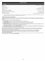
Engine Type .....................................................................................................
Air-Cooled,
Displacement ................................................................................................................
Operating RPM .........................................................................................................
2-Cycle
25 cc
6,500+ rpm
Idle Speed RPM ...................................................................................................
3,200 - 4,400 rpm
Spark Plug Gap ..................................................................................................
Lubrication .........................................................................................................
0.025 in. (0.635 mm)
Fuel/Oil Mixture
Fuel/Oil Ratio .................................................................................................................
Fuel Tank Capacity
40:1
..................................................................................................
10 fl.oz. (296 ml)
Approximate Unit Weight (No fuel, with cutting attachment, shield and D-handle)
Trimming Line Diameter .............................................................................
All specifications
notice.
are based on the latest product information
REPAIR PROTECTION
............................................
10 - 11 Ibs. (4.5 - 5 kg)
Hassle Free TM XTRA QUIET Spiral Line
available at the time of printing. We reserve the right to make changes at any time without
AGREEMENTS
Congratulations on making a smart purchase. Your new Craftsman@ product is designed and manufactured for years of dependable operation.
products, it may require repair from time to time. That's when having a Repair Protection Agreement can save you money and aggravation.
Here is what the Repair Protection Plan Agreement includes:
[]
Expert
[]
Unlimited
service
[]
Product
[]
Discount
preventive
by our 10,000
service
professional
and no charge
replacement
of 10% from
maintenance
repair
specialists
for parts and labor
up to $1500
regular price
checks
if your
cover
of service
But like all
on all covered
product
and related
repairs
can not be fixed
installed
parts not covered
by the agreement;
also,
10% off regular
price of
[]
Fast help by phone - we call it Rapid Resolution
- phone support from a Sears representative.
Think of us as a "talking owner's
manual."
Once you purchase the Repair Protection Agreement, a simple phone call is all that it takes for you to schedule service. You can call anytime day or night, or
schedule a service appointment online.
The Repair Protection Agreement is a risk-free purchase. If you cancel for any reason during the product warranty period, we will provide a full refund. Or a prorated
refund anytime after the product warranty period expires. Purchase your Repair Protection Agreement today!
Some limitations and exclusions appJy. For prices and additional information caJJ 1 =800=827=6655.
*Coverage in Canada varies on some items. For fulJ details caJJSears Canada at 1=800=361 =6665.
Sears InstaJJation Service
For Sears professional installation of home appliances, garage door openers, water heaters, and other major home items, in the U.S.A. or Canada call 1-800-4-MY-HOME ®.
10
Manual
del Operador
MRN
2-Tiempos
WEEDWACKER_
RECORTADOR
Model No. 316.791160
*
*
*
*
*
SEGURIDAD
MONTAJE
FUNCIONAMIENTO
MANTENIMIENTO
LISTADO DE PIEZAS
PRECAUCION: Lea el rnanuaJ deJ
operador y siga todas las
advertencias
e instrucciones de
seguridad.
Sears Brands
Management
Corporation,
Visite nuestro
769-06251
POO
Hoffman
Estates, iL 60179 U.S.A.
sitio web: www.craftsman.com
8/10
INDICE DE CONTENIDOS
Normas para una operaci6n segura ..............................
Garantia ...................................................
Conozca su unidad ...........................................
Instrucciones de ensamble .....................................
Los slmbolos de seguridad se utilizan para Ilamar su atenci6n sobre posibles
peligros. Los simbolos de seguridad y sus explicaciones merecen toda su
atenci6n y comprensi6n. Los simbolos de seguridad no eliminan ningQn peligro
por s[ mismos. Las instrucciones o advertencias que ofrecen no substituyen
las medidas adecuadas de prevenci6n de accidentes.
12
14
14
15
Informaci6n del aceite y del combustible ..........................
Instrucciones de arranque y apagado ............................
Instrucciones de operaci6n
....................................
Instrucciones de mantenimiento y reparaci6n ......................
Limpieza y almacenamiento
....................................
Resoluci6n de problemas ......................................
Especificaciones
.............................................
Lista de piezas ..............................................
Numeros de servicio ................................
15
16
17
17
18
20
21
22
Contraportada
SIMBOLO
NOTA:
Indica informaci6n o instrucciones de vital importancia
operaci6n o el mantenimiento del equipo.
para la
PELIGRO: El no obedecer una advertenciade seguridad puede
PARACHISPAS
conducir a que usted u otras personas sufrangraves lesiones.Siga
siempre las precaucionesde seguridad para reducir el riesgo de
incendio,descarga electrica y lesionespersonales.
NOTA: Para mosusuarios en tierras forestales de los EE.UU. yen mosestados de
California, Maine, Oregon y Washington. Todos los terrenos forestales de los EE.UU.
y el estado de California (C6digos de Recursos Peblicos 4442 y 4443), Oregon y
Washington, requieren per decreto, que ciertos motores de combusti6n intema que se
hagan funcionar en zonas boscosas y/o zonas cubiertas por pastizales, esten
equipados con un parachispas, que sean mantenidos en buen estado de
funcionamiento o que el motor sea construido, este equipado y sea mantenido para
evitar incendios. Consulte los reglamentos pertinentes a esos requisites con las
autoridades estatales o locales. El incumplimiento de esos requisitos puede
responsabilizarle o someterle a la imposici6n de una multa. Esta unidad rue equipada
en maf_brica con un parachispas. Si requiere sustituci6n, hay una Pantalla
Parachispas dispenible, Plaza #753-06182 al contactar el departamento de servicio.
PROPOSICION
SIGNIFICADO
ADVERTENClA:
El no seguir una advertencia de seguridad
puede conducir a que usted u otras personas sufran lesiones. Siga
siempre las precauciones de seguridad para reducir el riesgo de
incendio, descarga electrica y lesiones personales.
puede conducir a daSoElpatrimonial
o a advertencia
que usted u de
otras
PRECAUCION:
no seguir una
seguridad
personas sufran lesiones personales. Siga siempre las
precauciones de seguridad para reducir el riesgo de incendio,
descarga el6ctrica y lesiones personales.
65 DE CALIFORNIA
NOTA:
iEsta unidad puede utilizar un arrancador de potencia
electrico o el accesorio optional accesorio arrancador de
potencia para taladro!
Para informarse sobre el use adecuado de estos sistemas,
consulte el manual del operador del arrancador de potencia
electrico odel accesorio opcional accesorio arrancador de
potencia para taladro, i(Se incluye el arrancador de potencia
el6ctrico / el accesorio arrancador de potencia para taladro se
vende por separado! Vea en la pAgina 19 de este manual mas
informaci6n sobre estos accesorios).
Lea el manual del operador y siga todas las advertencias e instrucciones de
seguridad. De no hacerlo, el operador y/o los espectadores pueden sufrir
graves lesiones. Sl TIENE PREGUNTAS, LLAME AL 1=800=4=MY=HOME®
LAS EMISIONES DEL MOTOR DE ESTE PRODUCTO CONTIENEN
SUBSTANCIAS QUIMICAS QUE EL ESTADO DE CAMFORNIA CONOCE
COMO CAUSANTES DECANCER, DEFECTOS DE NACIMIENTO U OTROS
DAI_IOS REPRODUCTIVOS.
Toda la informaci6n, las ilustraciones y las especificaciones contenidas en este
manual se basan en la informaci6n mas reciente disponible en el memento de
impresi6n del manual. Nos reservamos el derecho de hacer cambios en
cualquier momento sin aviso previo.
• IMPORTANTE
LEA TODAS LAS INSTRUCCIONES
_
INFORMACION
ANTES DE OPERAR LA UNIDAD
•
normas de seguridad. Lea estas instrucciones antes de operarla a I
fin de garantizar la seguridad del operador y de cualquier otra
ADVERTENClA:
persona presente. AIGuarde
usar la estas
unidad nstrucc
deben ones
seguirse
paratodas
poderlas
usar as |I
mas adelante.
GENERAL
• Lea detenidamente las instrucciones.
uso adecuado de la unidad.
Familiaricese
•
Utilice solamente las piezas o accesorios de repuesto recomendados
para esta unidad, distribuidos por Sears ouna tienda Craftsman. Usar
cualquier otra pieza o accesorio de repuesto comprada en otra parte
puede ser peligroso y anulara su garantia.
Tenga en cuenta el riesgo de lesiones a la cabeza, las manos y los pies.
Aleje a los ni_os, personas presentes y animales dom6sticos del Area;
mant6ngalos fuera de un radio de 50 pies (15 m) como minimo. AOn asi,
todavia corren el riesgo de ser alcanzados per los objetos que salen
despedidos. Sugiera a los presentes usar protecci6n para los ojos. Si
alguien se le acerca, apague la unidad de inmediato.
]
SEGURIDAD
DE SEGURIDAD
con los controles y el
• Guarde estas instrucciones. ConsQItelas con frecuencia y utilicelas para
instruir a otros usuarios. Si le presta esta unidad a otras personas,
pr6stele tambien estas instrucciones.
Inspeccione cuidadosamente
el Area antes de encender la unidad. Retire
las piedras, vidrios rotes, clavos, alambres, cadenas y otros objetos que
podrian salir despedidos o enredarse en la unidad.
• No opere esta unidad siesta cansado, enfermo o bajo los efectos del
alcohol, drogas o medicamentos.
Apriete el control del regulador y compruebe que regrese
automaticamente
a la posici6n de marcha en vacio. Haga todos los
ajustes o reparaciones antes de usar la unidad.
Apague siempre la unidad cuando la operaci6n se demore o al caminar
de un lugar a otro.
Sostenga siempre la unidad con ambas manos al operarla. Agarre
firmemente ambas manijas o empu_aduras.
• Los niSos y adolescentes menores de 15 aSos no deben usar la unidad.
Los adolescentes pueden hacerlo bajo la supervisi6n de un adulto.
• Use la herramienta correcta. Use esta herramienta solamente para el
prop6sito previsto.
• Use la unidad Qnicamente a la luz del dia o con buena luz artificial.
No fuerce la unidad. El equipo funcionara mejor y con menos
probabilidad de accidentes a la velocidad para la que rue dise_ado.
Lleve puestas gafas o lentes de seguridad que cumplan con las normas
ANSI Z87.1 y est6n marcados como tales. Use siempre protecci6n para
los oidos al operar esta unidad. P6ngase una mascara facial o contra el
polvo si la operaci6n levanta polvo.
No intente alcanzar demasiado lejos ni Io use parade en superficies
inestables como escaleras, arboles, pendientes pronunciadas, techos,
etc. Mantenga siempre la posici6n y el equilibrio adecuados.
No opere la unidad a una velocidad mayor que la necesaria para realizar
el trabajo. No ponga a funcionar la unidad a alta velocidad si no Io estA
usando.
Use pantalones largos y gruesos, botas, guantes y camisa de mangas
largas. No use ropa holgada, alhajas, pantalones cortos, sandalias ni
ande descalzo. Asegure su cabello por encima del nivel de los hombros.
Inspeccione la unidad antes de utilizarla.
AsegQrese de que todos los sujetadores
Reemplace las piezas rajadas, melladas
No opere la unidad si tiene piezas flojas
Reemplace las piezas daSadas.
est6n en su sitio y asegurados.
o daSadas de cualquier forma.
o da5adas.
Si la unidad golpea o se enreda con un objeto extra_o, pare
inmediatamente la unidad y compruebe si ha habido algOn da_o. No
ponga a funcionar el equipo antes de reparar el da_o. No opere la unidad
si tiene piezas fiojas o da_adas.
Mantenga la unidad limpia de vegetaci6n y otros materiales que puedan
Todos los los accesorios de protecci6n y seguridad deben estar
correctamente instalados antes de comenzar a operar la unidad.
12
obstruir,
pegar
oatorar
laspiezas
enmovimiento,
Ioquepodria
ocasionar
lesiones
personales
graves
odafios
alaunidad.
• Mantenga
lasmanos,
lacaraylospieslejos
detodas
laspartes
m6viles.
Notratedetocarnidetener
ninguna
delaspiezas
m6viles
mientras
est6n
girando.
Deje
quelaunidad
seenfrie
antes
dealmacenarla
otransportarla.
Cerci6rese
deasegurar
launidad
altransportarla.
Nomoje
nunca
nirocie
launidad
conagua
niconningOn
otroliquido.
Mantenga
lasmanijas
secas,
limpias
ysinsuciedades.
Limpie
launidad
despues
decada
uso,lealasInstrucciones
deLimpieza
y
almacenamiento.
Guarde
launidad
enunlugar
seco,
bajoIlave
oenalto,afindeevitar
su
usonoautorizado
odafio.
Mant6ngala
fuera
delalcance
delosnifios.
SEGURIDAD
SOBRE
ELACEITE
YCOMBUSTIBLE
-_
pueden explotar si se encienden.
Tome
ADVERTENClA:
La gasolina
es las
muysiguientes
inflamableprecauciones:
y sus gases
i
No toque el motor, el bastidor del engranaje ni el silenciador. Estas partes
se ponen extremadamente calientes durante el funcionamiento y aun
despues de apagada la unidad.
Esta unidad tiene un embrague. El accesorio de la unidad permanece
estacionario cuando el motor estA en marcha en vacio. De no hacerlo, Ileve
la unidad a Sears o a otro distribuidor de servicio calificado para su ajuste.
DE LA RECORTADORA
Mantenga la unidad limpia de vegetaci6n y otros materiales.
trabarse entre el accesorio de la recortadora y el protector.
para disipar la
GUARDE ESTAS INSTRUCCIONES
DE SEGURIDAD
E INTERNACIONALES
_,
Este manual del operador describe los simbolos y figuras de seguridad e internacionales que pueden aparecer en este producto.
para obtener informaci6n completa acerca de la seguridad, ensamble, operaci6n y mantenimiento y reparaci6n.
MEANING
SYMBOL
a_
Pudieran
Mantenga las manos, la cara y los pies lejos de todas las partes m6viles. No
toque nitrate detener el accesorio de la recortadora mientras est6 girando.
• Verifique que la unidad no tenga fugas de combustible.
SYMBOL
o hacer
Ajuste la manija en Den la posici6n que proporcione el mejor agarre
posible.
Antes de arrancar la unidad, asegOrese de que el accesorio de la
recortadora no est6 en contacto con ningen objeto.
Use solamente la linea de repuesto de 0.095 pulg. (2.41 ram) de di&metro.
No use nunca la linea reforzada con metal, alambre, cadena o soga. Estas
lineas pueden romperse y convertirse en proyectiles peligrosos.
no estA bien
= SIMBOLOS
la bujia para darle mantenimiento
El protector del accesorio de la recortadora debe estar siempre en su sitio
mientras que se opere la unidad. No opere la unidad sin las dos lineas de
la recortadora extendidas y la linea correcta instalada. No extienda la linea
de corte m&s alia de la Iongitud del protector.
Nunca arranque ni opere la unidad dentro de una habitaci6n o edificio
cerrados. Respirar los gases de escape puede ser fatal. Opere esta
unidad solamente en un Area exterior bien ventilada.
lentamente
Evite los arranques accidentales. Debe estar en la posici6n de arranque
siempre que tire de la cuerda. El operador y la unidad deben estar en una
posici6n estable durante el arranque. Consulte las Instrucciones de
arranque y apagado.
SEGURIDAD
Evite el peligro de incendio debido a combustible derramado. Limpie de
inmediato todo combustible derramado de la unidad antes de encenderla.
Antes de arrancar el motor, aleje la unidad a una distancia de 30 pies (9.1
m) como minimo del lugar de abasto de combustible. No fume.
• Afloje la tapa del tanque de combustible
Para evitar el peligro de incendio, reemplace el silenciador y parachispas
defectuosos. Mantenga el motor y el silenciador sin hierbas, hojas, grasa
excesiva e incrustaciones de carb6n.
Apague el motor y desconecte
una reparaci6n.
Almacene el combustible solamente en los recipientes disefiados y
aprobados especificamente para estos materiales.
Pare siempre el motor y deje que se enfrie antes de Ilenar el tanque de
combustible. No quite nunca la tapa del tanque de combustible ni eche
combustible cuando el motor est6 caliente. No opere nunca la unidad si la
tapa del combustible no esta bien asegurada en su lugar.
• Mezcle o eche siempre el combustible en un Area exterior bien ventilada y
limpia, donde no haya chispas ni llamas. No fume.
• No opere nunca la unidad si la tapa del combustible
asegurada en su lugar.
presi6n del mismo.
• No guarde nunca la unidad con combustible en el tanque ni dentro de una
edificaci6n en la que los gases puedan ponerse en contacto con una
llama expuesta (luces pilotos, etc.) o chispas (interruptores, motores
el6ctricos, etc.).
_/:No
MEANING
_;!il
m
O:
COJ
01#
la
13
Lea el manual del operador
GARANTJA
TOTAL
POR 2 ANOS
DE CRAFTSMAN
Este producto se garantiza contra defectos de materiales o mano de obra POR 2 ANOS a partir de la fecha de compra. El producto
sin ningOn costo o serA remplazado gratuitamente si no puede ser reparado.
Para conocer los detalles de la cobertura de garantia para la reparaci6n o reemplazo, visite el sitio web: www.craftsman.com
Esta garantia
cubre SOLAMENTE
defectos
de rnateriales
o mane de obra.
La cobertura
de garantia
defectuoso
NO incluye:
• Los elementos consumibles que se desgasten debido al uso normal dentro del periodo de garantia, como lineas, filtros o bujias.
Los da_os al producto a consecuencia de intentos de modificaci6n o reparaci6n por parte del usuario u ocasionados por accesorios
Las reparaciones
El mantenimiento
contaminado.
ser& reparado
del producto.
necesarias debidas a un accidente o por no operar o mantener el producto de acuerdo con todas las instrucciones suministradas.
preventivo ni las reparaciones necesarias debido a una mezcla incorrecta de combustible o a al uso de un combustible viejo o
Esta garantia se anula si el producto en algOn momento se utiliza para prestar servicios comerciales o se alquila a otra persona. Esta garantia le confiere a
usted derechos legales especificos y usted puede tener otros derechos que difieren de un estado a otro.
Sears Brands Management
Corporation,
Hoffman Estates, IL 60179
APLICAClONES
Como recortadora:
Cortar c6sped y malas hierbas escasas.
Orillar (bordear)
• Hacer recortes decorativos alrededor de &rboles, cercas, etc.
Con esta unidad se pueden utilizar otros accesorios
Silenciador
Bujia
de encendido
opcionales.
Manija de la cuerda
de arranque
Control
de
encendido
Mango
del eje
y apagado
Cubierta
del filtro
Manija en D
de aire
Tapa del combustible
Bastidor
del
Control del
regulador
eje
Convertible
acoplador
Protector
Cabezam
Hassle
de
cabezam
de corte
Free®
14
de
corte
TM
Bombilla
del
cebador
ADJUSTE DE LA MANIJA END
Mango
1.
Afloje el perno que esta en la
manija Io suficiente para
moverla (Fig. 1).
2.
Mientras sujeta la unidad en
la posici6n de
funcionamiento (Fig. 9),
Minirno de
mueva la manija en D hacia
15,24 cm
el lugar que le proporcione el (6 pulgadas}
3.
mejor agarre.
Apriete el perno hasta que la
manija en D est6 segura
(Fig. 1).
OPERAR EL SlSTEMA
• Agite siempre la mezcla de combustible
Uso de aditivos
Manija
Optima el bot6n de
desconexi6n y mant6ngalo
oprimido (Fig. 2).
CONVERTIBLE
permite usar estos accesorios
sobre los accesorios, Ilame al 1-800-
_----__
Bastidor
eje superior
eje
Fig.
del
inferior
Fig. 3
coloque la unidad sobre el
Para afiojar, gire la perilla en
Acoplador de
sentido contrario alas agujas
Convertible
/
TM
del reloj (Fig. 3).
-i------x_
2.
Mientras sostiene el
accesorio con firmeza,
introdOzcalo directamente en __
el acoplador Convertible TM
(Fig. 2).
NOTA:
Alinear el bot6n de
desconexi6n con el
agujero de guia facilitara
la instalaci6n (Fig. 4).
Bot6n de desconexi6n
NOTA:
Un gal6n (3.8 litros) de combustible sin plomo mezclado con una
botella de 3.2 oz. (95 ml) de aceite para motores de 2 tiempos
representa una proporci6n de combustible/aceite
40:1.
NOTA:
Deseche la mezcla vieja de combustible/aceite
regulaciones federales, estatales y locales.
-?!-T
I_
I_
I_
Befinicibn
2.
I_
combustible
alas
DE COMBUSTIBLE
LA UNIDAD
fin de evitar lesiones por salpicaduras.
I ADVERTENCIA:
Quite no
lentamente
si la tapa del combustible
estA bien
No opere nunca la unidad
la
tapa de combustible
asegurada
en su lugar. a
Coloque la unidad sobre el costado, con la tapa del tanque de
combustible mirando hacia arriba y quitele la tapa.
EL ACEITE Y EL COMBUSTIBLE
Un combustible viejo y/o mal mezclado es la principal causa de que la
unidad no funcione bien. AsegOrese de usar un combustible fresco, limpio
y sin plomo. Siga atentamente las instrucciones para mezclar
adecuadamente el aceite/combustible.
de combustibles
conforme
prenderse, los gases pueden hacer explosi6n. Pare siempre el
motor y deje que se enfrie antes de Ilenar el tanque de
combustible. No fume La
mientras
el tanque. Mantenga
ADVERTENCIA:
gasolina Ilena
es sumamente
inflamable. De
alejadas del Area las chispas y llamas expuestas.
ABASTERCER
Fig. 4
1.
PARA MEZCLAR
I
Hueco de guia
3.
Para apretar, gire la perilla en el sentido de las agujas del reloj (Fig. 3).
Para hacer recortes/bordeados
decorativos con el cabezal de corte, trabe el
bot6n de desconexi6n en el orificio de 90 ° (Fig. 3).
INSTRUCCIONES
confiabilidad del motor, hay que prestar rigurosa atenci6n a las
instrucciones para mezclar el aceite y el combustible que estan en
el recipiente del aceitePara
ADVERTENCIA:
parael motores
funcionamiento
de 2 tiempos.
adecuado
El uso
y maxima
de un
I
combust b e ma mezc ado puede dafiar ser amente e motor,
j
gasolina STA-BIL® o similar.
Agregue 0.8 onzas (23 ml) de
ACEITE PARA
aditivo por gal6n de combustible
GASOLINA SIN
MOTOR DE 2
segQn las instrucciones del
PLOMO
TIEMPOS
recipiente. No afiada NUNCA los
1 GALON EE. UU.
3.20NZAS
aditivos directamente en el tanque
de combustible de la unidad.
(3.8 LITROS)
LiQUIDAS. (95 ml)
Mezcle bien el aceite para motor
1 LITRO
25 mL
de 2 tiempos con combustible sin
plomo en la proporci6n correcta,
PROPORClON
- 40:1
en una lata aparte para
combustible. Use una proporci6n de combustible/aceite
40:1 No los mezcle
directamente en el tanque de combustible del motor. Vea en la tabla las
proporciones especificas de las mezclas de gasolina y aceite.
SI...
la unidad vino con una botella de aceite para motor de 2 tiempos,
vierta la botella entera en 1 gal6n de gasolina y m6zclelos bien.
2
Mientras sostiene la caja del
eje superior con firmeza, hale
en linea recta y hacia afuera
la cubierta inferior del eje del
acoplador Convertible TM (Fig.
4).
Instalar el accesorio
1.
para el combustible
Si no es posible, utilice un buen
aceite para motores de 2 tiempos
enfriados por aire elaborado con un
aditivo como el estabilizador de
Orificio lateral 90 °
Para facilitar la
instalaci6n o remoci6n del accesorio,
suelo o sobre un banco de taller.
la unidad
En esta unidad se recomienda usar el aceite para motor de 2 tiempos del
fabricante. Si es inevitable, use un buen aceite de 2 ciclos elaborado para
motores enfriados por aire junto con un aditivo para el combustible como
por ejemplo el estabilizador de gasolina STA-BIL® o similar. Agregue 23 mL
(0,8 onzas) de aditivo de combustible por gal6n de combustible de acuerdo
con las instrucciones del envase. NUNCA agregue aditivos directamente en
el tanque de combustible de la unidad.
Mezclar el combustible
Hoyo primario
_,
I
TM
3.
NOTA:
antes de abastecer
en D
Bastidor del
Para afiojar, gire la perilla en
sentido contrario alas agujas
del reloj (Fig. 3).
indicada en su manual
Drene el tanque y eche a andar el motor en seco antes de guardar la unidad
"'_'__-_X
Sierra de p6rtiga
Recortadora de setos
Quitar el accesorio
2.
• Utilice siempre la mezcla fresca de combustible
del operador
I_
TM
mezclados
Si decide usar un combustible mezclado, o no puede utilizar otro, le
recomendamos tomar las siguientes precauciones:
Perno
Fig. 1
El sistema del acoplador Convertible
opcionales. Para obtener informaci6n
4-MY-HOME®.
• Recortador de bordes
1.
Uso de combustibles
Bastidor del eje
eje
_
DE ACOPLADOR
• Cultivadora
Turbosopladora
del
mezclados
con mAs de 10% de etanol dafie este motor, Io que
Se ha comprobado que es probable que el
I ADVERTENOIA:
anularA la garantia.
Los combustibles actuales con frecuencia son una mezcla de gasolina e
hidrocarburos oxigenados como el etanol, metanol o MTBE (6ter). El
combustible mezclado con alcohol absorbe agua. Un 1% de agua es
suficiente para separar la mezcla de aceite y alcohol. AI guardarla, se
forman acidos. Si utiliza combustible mezclado con alcohol, Qselo siempre
fresco (con menos de 30 dias)
15
1
I
y bien ventilada. Limpie de inmediato todo el combustible
I
derramado. Evite el peligro de incendio debido a combustible
derramado.
No arranque
hasta que
hayan
d s pado
ADVERTENCIA:
Echee elmotor
combustible
en no
un se
Area
exterior
liana I
los vapores de combustible.
Coloque la boquilla del dep6sito
tanque de combustible y
116nelo.(Fig. 5)
NOTA:
No rebose el tanque.
3.
Limpie toda la gasolina que
pueda haberse derramado.
4.
Vuelva a colocar la tapa del
tanque de gasolina.
5.
Antes de arrancar el motor,
aleje la unidad a una
distancia de 30 pies (9.1 m)
como minimo del lugar de
abasto de combustible.
1
de gasolina en el orificio de Ilenado del
Fig. 5
I
J
exterior bien ventilada. El mon6xido de carbono de los gases de
ADVERTENClA:
solamente en un &rea
escape puede ser letalOpere
en unesta
Areaunidad
reducida.
_
NOTA:
|
de estar en la posicidn
de arranque al tirar de la cuerda (Fig. 8). A
graves,
operador yaccidentales.
la unidad deben
estar ]
Evite loselarranques
Cerci6rese
en una posici6n estable durante el arranque.
de evitar lesiones
I fin
ADVERTENCIA:
__
iNSTRUCCJONES
1.
NOTA:
Esta unidad utiliza el sistema de arranque Incredi-Pull TM, que
reduce notablemente el esfuerzo necesario para tirar de la soga de
arranque.
INSTRUCCJONES
1.
2.
3.
4.
DE ARRANQUE
Oprima y suelte despacio
por completo la pera del
cebador 10 veces. DeberA
verse alguna cantidad de
combustible en la pera del
cebador yen las tuberias de
combustible (Fig. 7). Si no se
ve combustible en la pera,
oprima y suelte la pera hasta
que se vea el combustible.
De vuelta a la palanca del
obturador en sentido de las
6.
7.
SL.
i__(-,_'_
3.
4.
palanca del
cebador
Oprima y mantenga oprimido el bot6n ON (I) del arrancador el6ctrico
con enchufe o del Power Bit Start equipado con taladro a intervalos no
mayores de 4 segundos hasta que la unidad arranque.
7.
Espere y deje que la unidad funcione en marcha en vacio por unos 5 a
10 segundos. Si la unidad deja de funcionar durante este tiempo,
apriete el control del regulador y, despu6s, oprima y sostenga el bot6n
ENCENDIDO (ON) (I) del arrancador el6ctrico con enchufe o del Power
Bit Start equipado con taladro a intervalos no mayores de 4 segundos
hasta que la unidad arranque.
Quite el arrancador el6ctrico con enchufe o el taladro de la unidad.
9.
SL.
SL.
Fig. 7
La Posici6n
que empieza
Apriete y sostenga el control del regulador durante 30 a 60 segundos
para que la unidad se caliente.
El motor no arranca, regrese al paso 3.
El motor no arranca despues de varios intentos, apriete el control del
regulador y, despues, oprima y mantenga oprimido el bot6n de
encendido (ON) (I) del arrancador el6ctrico con enchufe del taladro a
intervalos no mayores de 4 segundos cada vez, hasta que la unidad
arranque.
INSTRUCOIONES
Fig. 8
Si la unidad est& caliente y no arranca despu6s de haber tirado 3
veces de la cuerda de arranque, oprima el control del regulador y
tire de la cuerda hasta que la unidad arranque.
INSTRUCOIONES
6.
8.
Apriete y sostenga el control del regulador durante 30 a 60 segundos
para que la unidad se caliente.
El motor no arranca, regrese al paso 3.
NOTA:
Ag&chese en la posici6n de arranque (Fig. 8). No oprima el regulador.
Coloque el enchufe el arrancador el6ctrico con enchufe o el Power Bit
Start en la parte trasera de la unidad. Consulte la secci6n Operaci6n
del manual del operador del arrancador el6ctrico con enchufe o del
Power Bit Start.
e
Bornbilla
del cebador_ k }
No hay necesidad de arrancar la unidad. El control de
Encendido/Apagado
est& en la posici6n ENCENDIDO ( I ) en todo
momento (Fig. 6).
Oprima y suelte despacio por completo la pera del cebador 10 veces.
Deber& verse alguna cantidad de combustible en la pera del cebador
(Fig. 7). Si no se ve combustible en la pera, oprima y suelte la pera
hasta que se vea el combustible.
D6 vuelta a la palanca del obturador en sentido de las agujas del reloj
hasta que encaje en su lugar (Fig. 7).
5.
Control del
regulador
Fig. 6
Ag&chese en la posici6n de
arranque (Fig. 8). No oprima
el regulador. Tire de la
cuerda de arranque con un
movimiento firme hasta que
la unidad arranque.
Espere y deje que la unidad
funcione en marcha en vacio
por unos 5 a 10 segundos. Si
la unidad se detiene durante
este tiempo, presione el
control del regulador y tire de
la cuerda de arranque con un
movimiento firme hasta que
la unidad arranque.
DE ARRANQUE
Mezcle la gasolina con aceite. Vea las Instrucciones para mezclar el
aceite y el combustible.
Llene el tanque de combustible con mezcla limpia y fresca. Consulte
"Abastecer de combustible la unidad".
NOTA:
No hay necesidad de
arrancar la unidad. El
control de
Encendido/Apagado
esta en la posici6n
ENCENDIDO (I) en todo
momento (Fig. 6).
agujas del reloj hasta que
encaje en su lugar (Fig. 7).
5.
2.
Mezcle la gasolina con aceite. Vea las Instrucciones para mezclar el
aceite y el combustible.
Llene el tanque de
Apagado (O} -_
combustible con mezcla
_
,., ,,,
_
limpia y fresca. Consulte
"Abastecer de combustible
la unidad".
NOTA:
iEsta unidad puede usar un arrancador
eJ_ctrico o un
accesorio opcJonaJ Power Bit Start! i
Para utilizar correctamente estos dispositivos, consulte el manual
del operador del arrancador el6ctrico o del accesorio Power Bit
Start! (iLos accesorios se venden por separado! Para informarse
m&s sobre la compra de estos accesorios, vaya a la p&gina 8 de
este manual).
DE APAGADO
1.
Suelte el control del regulador y deje que el motor se enfrie
funcionando a la velocidad de marcha en vacio.
2.
Presione y mantenga oprimido el interruptor de control de Encendido y
Apagado en la posici6n APAGADO (O) hasta que el motor se detenga
por completo (Fig. 6).
16
DE APAGADO
1.
Suelte el control del regulador y deje que el motor se enfrie
funcionando a la velocidad de marcha en vacio.
2
Presione y mantenga oprimido el interruptor de control de Encendido y
Apagado en la posici6n APAGADO (O) hasta que el motor se detenga
por completo (Fig. 6).
COMO SOSTENER
EL RECORTADOR
PROGRAMA
!
_
J
protecci6n del pie y del cuerpo para reducir el riesgo de lesi6n al
funcionar esta unidad. Siempre ojo del desgaste, el oir,
ADVERTENClA:
|
Antes de operar esta unidad,
parese en posici6n de operaci6n
(Fig. 9). Verifique Io siguiente:
• El operador tiene protecci6n
ocular y ropa adecuada.
• El brazo derecho esta levemente
doblado, y la mano esta
sosteniendo el mango del eje.
El brazo izquierdo esta recto y
la mano sostiene la manija en D.
PARA OBTENER
NOTA:
Es posible que algunos procedimientos de mantenimiento
precisen de herramientas o habilidades especiales. Para
informarse mAs acerca de este tipo de reparaciones, Ilame al
1-800-4-MY-HOME@.
NOTA:
Para ver la lista completa de t6rminos y la cobertura de los
dispositivos de control de emisiones como parachispas,
silenciador, carburador, etc., lea la declaraci6n de California/EPA
que viene junto con la unidad.
FRECUENCIA
MEJORES
Cada 25 horas
Revise la abertura de la bujia de encendido y
el estado en que se encuentra
p. 18
para la Cabeza de Corte Hassle-Free
NOTA:
Recorte Onicamente cuando el pasto y las hierbas est6n secas.
• La vida de su linea de corte depende de:
Seguir todas las t6cnicas de corte indicadas anteriormente
El tipo de vegetaci6n que corte
El lugar donde se corta
Por ejemplo, la linea se
desgastara mAs rApido cuando
corte contra un muro que cuando
corte alrededor de un Arbol.
30o
[
\
• Intentar cortar hierbas gruesas
y lefiosas
Forzar la linea en objetos como paredes o postes de cercos.
REOORTE DEOORATIVO
Gire toda la unidad a modo de que el accesorio
Angulo de 30 ° con el suelo (Fig 10).
Antes de insertar la nueva linea en los agujeros de la cabeza de
corte, identifique los
agujeros adecuados.
Placa de Deslizamiento
de la Linea
Siga las directrices que
se indican en la placa de
Flecha
deslizamiento de la
linea. No trate de
quitarle la cabeza de
corte a la unidad al
reemplazar la linea.
1.
Quitele a la cabeza de corte
la linea vieja y la placa de
deslizamiento de la linea.
2.
Limpie toda la superficie
la cabeza de corte.
3.
Reinstale la placa de
deslizamiento (Fig. 11).
de alrededor
de corte se ubique a un
4.
Accesorio
de corte
de
A- al usar la linea mediana (roja)
Alinee la flecha con:
o grande (negra)
B- al usar lineas con diametros
inferiores a la linea mediana
(roja)
NOTA:
La placa de
deslizamiento de la linea
se debe reinstalar en la
cabeza de corte antes
de insertar la nueva
linea.
Fig. 10
El recorte decorativo se realiza eliminando toda la vegetaci6n
de los Arboles, postes, cercos, etc.
TM
Use siempre la Linea Espiral Hassle-Free TM XTRA QUIET de Craftsman@.
Seleccione el tamafio de la linea que mejor se adapte al trabajo que se
propone realizar. La linea de color rojo esta disefiada para cortar hierba y
pequefias malezas. La linea de color negro esta disefiada para cortar
malezas de mayor tamafio y matorrales ligeros.
• Mueva lentamente el recortador dentro y fuera del Area de corte a la altura
deseada. Realice movimientos ya sea de adelante hacia atras y viceversa, o de
lado a lado. El corte en longitudes mas cortas produce mejores resultados.
_
DE LA L|NEA
alambre, cadena ni soga, etc. Estos elementos pueden
DVERTENOIA:
No useennunca
linea reforzada
desprenderse
y convertirse
un proyectil
peligroso. con metal,
_
• No fuerce el accesorio de corte. Permita que la punta de la linea realice el
corte (en especial a Io largo de paredes). Si corta con mAs de la punta
reducira la eficacia del corte y puede sobrecargar el motor.
Corte cesped de mas de 200 mm (8 pulgadas) trabajando de arriba hacia
abajo en pequefios incrementos para evitar el desgaste prematuro de la
linea y el arrastre del motor.
Corte de derecha a izquierda siempre que sea posible. Cortar hacia la
izquierda mejora la eficiencia de la unidad. Los recortes salen arrojados
en sentido contrario al operador.
OBSERVAR
p. 18
REEMPLAZO
de corte es paralelo al suelo.
NECESARHO
Limpie y vuelva a engrasar el filtro de
aire
RESULTADOS AL RECORTAR
• El Angulo correcto para ubicar el accesorio
La linea puede cortarse por:
Enredarse con un objeto
extrafio
• Fatiga normal de la linea
MANTENIMIENTO
Cada 10 horas
v,J
• La unidad esta debajo del nivel
de la cintura.
Fig. 9
• El accesorio de corte esta
paralelo al suelo y hace facil contacto con la vegetaci6n que va a ser
cortada sin que el operador tenga que inclinarse.
CONSEJOS
DE MANTENIMIENTO
Lleve a cabo los procedimientos
necesarios de mantenimiento con la
frecuencia indicada en la tabla. Estos procedimientos deberian tambien
formar parte de cualquier afinamiento de temporada.
Inserte ambos extremos de
su linea a traves de los
agujeros adecuados en el
lado de la cabeza de corte
Fig. 11
_
T_nel de
1!
f_l
Posicionamiento
/_
%d
Fig. 12
Linea
contra
el cubo
(Fig. 12).
Hale la linea y cerci6rese de
que la linea est6 contra el
cubo y que este totalmente
extendida a trav6s de los
T_nel de
tOneles de posicionamiento
Posicionamiento
(Fig. 13).
Fig. 13
6.
La linea que est6 instalada
correctamente tendra la misma Iongitud en ambos lados.
NOTA:
No apoye la perilla percuisva sobre el suelo mientras la unidad est6
en funcionamiento.
5.
17
MANTENIMIENTO
m
DEL FILTRO DE AIRE
IA
ajustes de la marca en vacio. Use ropa de protecci6n y observe
todas las instrucciones de seguridad para evitar lesiones
DVERTENCIA: El cabezal de corte puede girar durante los
personales graves.
_
3.
Limpieza del filtro de aire
Es importante darle mantenimiento al filtro de aire. No dar mantenimiento
filtro de aire correctamente puede hacer que el motor funcione real o
causarle da_o permanente.
1.
Abra la tapa del filtro de aire
presionando sobre la
lengOeta de cierre hacia
adentro y tirando de la tapa
del filtro de aire (Fig. 14).
2.
Quite el filtro de aire (Fig. 14).
3.
Lave el filtro con detergente y
agua. Enjuague bien el filtro y
d6jelo secar.
Aplique suficiente aceite
limpio de motor SAE 30 para
recubrir ligeramente el filtro.
4.
5.
al
de cierre
Filtro
de
110=120 pulg olb. (12.3-13.5
No apriete demasiado.
aire
EN VACJO
Espere a que el motor se enfrie para guardar la unidad.
Guarde la unidad con Ilave para evitar su daSo o uso no autorizado.
Guarde el cargador en un lugar seco y bien ventilado.
Guarde la unidad fuera del alcance de los ni_os.
Los ajustes negligentes pueden da_ar seriamente la unidad. Los
ajustes del carburador deben ser hechos por un distribuidor de
servicio autorizado.
3.
Suelte el gatillo del regulador
y deje que el motor se
mantenga en marcha en
vacio. Si el motor se detiene,
inserte un destornillador
peque_o phillips en el tornillo
de ajuste de marcha en vacio
(Fig. 23). Gire el tornillo de
marcha en vacio en sentido
ALMACENAMIENTO
1.
2.
3.
Tornillode
ajuste de
marcha en
vac{o
4.
Fig. 15
Espere a que el motor se enfrie. Quitele la bujia y eche de 3 a 5 gotas
de cualquier aceite de motor de 2 tiempos de alta calidad en el cilindro.
Tire lentamente de la cuerda de arranque para distribuir el aceite.
Vuelva a poner la bujia.
Saque la bujia y drene todo el aceite del cilindro antes de intentar
arrancar de nuevo la unidad despues de estar almacenada.
Limpie bien la unidad y compruebe que no haya piezas sueltas o
daSadas. Repare o reemplace las piezas daSadas y apriete los tornillos,
tuercas o pernos sueltos. La unidad est& lista para guardarse.
CON ENCHUFE Y POWER START BIT
Esta unidad se puede arrancar utilizando un
arrancador el6ctrico con enchufe o un Power Start
Bit (estos componentes pueden venderse por
separado). Si opta por arrancar la unidad utilizando \
uno de estos sistemas o tiene alguna pregunta,
comuniquese con el distribuidor Craftsman de su
-_
Iocalidad o Ilame al 1-800=4-MY-HOME®
para m_s
informaci6n y la compra. Tambien puede ira
www.oraftsman.com.
Sistema
o, os,vos,.., c
• el motor falla o se cala al acelerar
• hay una p@dida de potencia del motor
Lleve el carburador a un distribuidor de servicio autorizado para que Io ajuste.
Articulo No.
316.85951 ....................................................
LA BUJJA DE ENCENDIDO
Arrancador
Detenga el motor y d6jelo enfriar. Agarre firmemente el cable de la bujia
y sAquelo de la bujia.
Limpie alrededor de la bujia. Saque la bujia de la culata gir&ndola en
sentido contrario a las agujas del reloj con una Ilave de bujia de 5/8 de
pulgada.
18
-_
de arranque
el_ctrico
Descripci6n
el6ctrico con enchufe
316.85952 .................................................................................
Use la pieza de repuesto No. 753-06193, una bujia Champion RDJ7J, o el
equivalente. La abertura correcta de la bujia es de 0.025 pulgadas (0.635 mm).
2.
utilice el
Drene todo el combustible del tanque hacia un contenedor con la
misma mezcla de combustible para motor de 2 tiempos. No use el
combustible que Ileve almacenado m&s de 30 dias. Deseche la mezcla
vieja de combustible/aceite
conforme alas regulaciones federales,
estatales y locales.
Arranque el motor y d6jelo funcionar hasta que pare. Con esto se
asegura drenar todo el combustible del carburador.
NOTA:
Comprobar la mezcla de combustible, limpiar el filtro de aire y ajustar la
marcha en vacio, deberian resolver la mayoria de los problemas del motor.
De Io contrario y ser cierto todo Io siguiente:
• el motor no funciona en marcha en vacio
1.
A LARGO PLAZO
Si tiene planeado guardar la unidad un tiempo prolongado,
siguiente procedimiento:
de las agujas del reloj 1/8 de vuelta cada vez (segOn sea necesario)
hasta que el motor funcione en marcha en vacio sin inconvenientes.
Sial parecer el motor est& funcionando en marcha en vacio muy
r&pido, gire el tornillo de marcha en vacio en sentido contrario a las
agujas del reloj 1/8 de vuelta cada vez (segOn sea necesario) para
reducir la marcha en vacio.
CAMBIAR
N_m}
No guarde nunca la unidad con combustible en el tanque en un lugar en
el que las emanaciones puedan ponerse en contacto con una llama
expuesta o chispas.
Si, luego de verificar la mezcla de combustible y limpiar el filtro de aire, el
motor aOn no se mantiene en marcha en vacio, ajuste el tornillo de
regulaci6n de marcha en vacio de la siguiente manera:
1.
Arranque el motor y dejelo
funcionar un minuto para que
se caliente. Consulte las
Instrucciones de arranque y
apagado.
2.
Fig. 16
ALMACENAMIENTO
La velocidad de marcha en vacio del motor se puede ajustar. Hay un tornillo
de regulaci6n de marcha en vacio entre la tapa del filtro de aire y la carcasa
del motor de arranque (Fig. 15).
NOTA:
t
Use un cepillo peque_o para limpiar la parte exterior de la unidad. No utilice
detergentes fuertes. Los limpiadores caseros que contienen aceites
arom&ticos como el pino y el lim6n, y los disolventes como el queroseno,
pueden daSar la caja de pl&stico o la manija. Limpie la humedad con un
paso suave.
Vuelva a instalar la tapa del filtro de aire. Coloque las dos lengOetas
peque_as de la tapa del filtro de aire en las dos ranuras y empuje la
tapa del filtro de aire hacia abajo, asegur&ndose de alinear la lengOeta
del seguro con la ranura de la lengOeta, hasta que encaje en su lugar
(Fig. 14).
DE MARCHA
0.025 in.
(0.635 ram)
LIMPIEZA
Fig. 14
Exprima el filtro para esparcir y eliminar el exceso de aceite.
AJUSTE DE LA VELOCIDAD
con
Reemplace la bujia siestA
rajada, corroida o sucia.
Ajuste la abertura de la bujia
a 0.025 pulgadas (0.635 mm)
con la ayuda de un
calibrador de hoja (Fig. 16).
Instale una bujia con la
abertura correcta en la culata
del motor. Gire el receptaculo
de 5/8 de pulgada en sentido
de las agujas del reloj para
apretarlo hasta que quede
ajustado.
Si usa una Ilave dinamom6trica,
apriete a:
6.
Vuelva a colocar el filtro de aire en la placa de base (Fig. 14).
NOTA:
Si opera la unidad sin el filtro de aire, la garantia serA ANULADA.
7.
No sople, raspe ni limpie los electrodos
_arena. La arenisca en el motor puede da_ar el cilindro.
4.
Cubierta del
filtro de aire
Leng_eta
I ADVERTENCIA:
_
Power Bit Start
CAUSA
El tanque de combustible
Combustible
ACClON
estA vacio
Llene el tanque de combustible
viejo
con combustible
Drene el tanque de gasolina y aSada combustible
El filtro de aire esta obstruido
Cambie o limpie el filtro de °ire
Combustible
Drene el tanque de gasolina y afiada combustible
viejo
19
fresco
fresco
Tipo de motor ..........................................................................................
Cilindrada .................................................................................................................
Enfriado por aire, de 2 tiempos
25 cc
RPM de operaci6n ........................................................................................................
6,500 rpm
RPM de marcha en vacio ...........................................................................................
3,200 - 4,400 rpm
Abertura de la bujia ........................................................................................
Lubricaci6n .............................................................................................
Proporci6n
de aceite/combustible
Capacidad
del tanque de combustible
0.025 pulgadas (0.635 mm)
Mezcla de aceite/combustible
...............................................................................................
40:1
...........................................................................
10 onzas liquidas (296 ml)
Peso aproximado de la unidad (sin combustible) ......................................................................
Diametro del Area de corte .......................................................................................
10 - 11 Ibs. (4.5 - 5 kg)
16 pulgadas (40.64 cm)
DiAmetro de la linea de corte .......................................................................
Linea Espiral Hassle Free TM XTRA QUIET
Toda las especificaciones contenidas en este manual se basan en la informaci6n mas reciente disponible
reservamos el derecho de hacer cambios en cualquier momento sin aviso previo.
CONVENIO
DE PROTECCION
en el momento de impresi6n del manual. Nos
DE REPARACION
Felicidades por haber realizado una compra inteligente. Su nuevo producto Craftsman® esta. disehado y fabricado para ofrecerle ahos de funcionamiento confiable. Pero
come todos los productos, es posible que sea necesario repararlo de vez en cuando. Ahi es cuando tener un Convenio de Protecci6n de Reparaci6n puede ahorrarle dinero
y problemas.
Esto es Io que incluye el Convenio
[]
Servicio
experto
[]
Servicio
ilimitado
[]
Reemplazo
[]
Descuento
descuento
de Protecci6n
de Reparaci6n*:
de nuestros
10,000
especialistas
y sin costo
alguno
por piezas
del producto
profesionales
y mano
per un valor de hasta $1500
en reparaciones
de obra en todas
si el producto
las reparaciones
cubierto
cubiertas
no se puede
del 10% en el precio regular del servicio, asi como de las piezas instaladas,
en el precio regular de comprobaci6n
de mantenimiento
preventivo
reparar
que el convenio
no cubra;
igualmente,
10% de
[]
Ayuda r_pida
pot tel6fono
- la Ilamamos
Soluci6n
R_pida - asistencia
tecnica per telefono de un representante
de Sears. Piense en
nosotros
como si fueramos
un "manual del usuario que habla".
Una vez que adquiera el Convenio de Protecci6n de Reparaci6n, todo Io que necesita es hacer una simple Ilamada para programar el servicio de reparaci6n. Puede
Ilamar a cualquier hora del dia o de la noche, o hacer una cita de servicio por Internet.
El Convenio de Protecci6n de Reparaci6n es una compra libre de riesgo. Si usted cancela por cualquier motivo durante el periodo de garantia del producto,
proporcionaremos un reembolso completo. O, un reembolso prorrateado en cualquier momento despues de que venza el periodo de garantia del producto.
iAdquiera hoy mismo su Convenio de Protecci6n de Reparaci6n!
Aplican algunas limitaciones y exclusiones. Para obtener precios e informacibn adicional en los Estados Unidos, Uame al 1=800=827=6655.
*La cobertura
en Canad_ varia en algunos
SERVIClO DE INSTALACION
articulos.
Para obtener todos
los detalles,
Uame a Sears en Canad_
al 1-800-361-6665.
SEARS
Para la instalaci6n de electrodom6sticos,
abridores de puertas de garaje, calentadores
en los Estados Unidos o CanadA, Ilame al 1-800-4-MY-HOME
®.
20
de agua, y otros productos
para el hogar por profesionales
de Sears,
21
REPLACEMENT
PARTS - MODEL 316.791160
2-CYCLE TRIMMER
PPN 41AD326C799
item
1
Pa_ No.
753-06177
item
19
Description
Rear Cover Assembly (includes 2 & 34)
Cover Screw
Pa_ No.
791-182723
Description
Crankcase Bolt
20
753-06275
21
22
753-06189
753-06184
Crankcase O-Ring
Insulator Assembly
2
791-181345
3
4
791-181862
753-06174
Housing Screw
5
753-06175
753-06185
753-06247
753-06218
Flywheel Assembly
Washer
23
6
7
24
753-06288
Carburetor O-Ring
Carburetor
8
753-06530
Spacer
Starter Housing (includes 3 & 13)
25
26
753-06500
753-06417
Aircleaner Cover Assembly
Aircleaner Filter
9
10
753-05860
753-06181
Clutch Assembly
27
28
753-06188
753-06187
Throttle Cable
Lead Wires
11
753-06418
29
791-182519
Anti-rotation
12
13
753-06419
791-182366
30
31
753-04003
791-180217
Clamp Screw
14
753-06183
32
753-06253
15
16
791-181930
791-182612
33
34
753-06294
791-182195
17
753-06303
Fuel Cap
Module Assembly
35
753-06173
Rear Housing Screw
Electric Starter Cover Assembly
18
753-06193
Spark Plug
36
753-06523
Short Block Assembly
O-Ring
Clutch Cover (includes 2)
Muffler Assembly (includes 12 & 33)
Muffler Gasket
U-shaped
Nut
Fuel Tank Assembly (includes 15 & 16)
Tank Screw
22
(includes 22 & 23)
Insulator O-Ring
(includes 26)
Screw
Clamp Nut
Air Cleaner Gasket
Muffler Screw
(includes 4-7 & 17-20)
REPLACEMENT
PARTS - MODEL 316.791160
2-CYCLE TRIMMER
PPN 41 AD326C799
item
1
2
3
4
5
6
7
8
9
10
11
12
13
14
15
16
17
18
19
20
21
22
23
*
*
Part
No.
753-04234
753-04119
791-182690
791-182405
753-04344
753-06039
753-06040
753-1190
791-181617
791-182057
791-181981
753-04386
791-182387
791-181852
791-180531
753-05033
753-05032
791-153597
791-145569
753-05050
753-05034
753-05035
753-05036
753-05038
Description
Throttle Housing Assembly (includes 2-4)
Throttle Trigger
Throttle Trigger Spring
Switch Assembly
Upper Drive Shaft Housing
Deluxe D-Handle Assembly (includes 7)
Handle Bolt
Split Boom Coupler (includes 9-12)
Bolt
Anti-Rotation Screw
Adjustment
Nut
Knob (includes 12)
Lower Drive Shaft Housing (includes 14)
Lower Flexible Drive Shaft
Shield Mount Hardware
Blade Assembly
Shield Assembly (includes 16)
Lower Clamp Assembly (includes 19)
Anti-Rotation Screw
Bushing Housing Assembly
Adapter
Cutting Head Assembly
Glide Plate
Tube of Precut Line
Items Not Shown
23
For troubleshooting,
Your Home
product manuals and expert advice:
managemylife
www.managemylife.com
For repair - in your home - of all major brand appliances,
lawn and garden equipment, or heating and cooling systems,
no matter who made it, no matter who sold it!
For the replacement parts, accessories and
owner's manuals that you need to do-it-yourself.
For Sears professional installation of home appliances
and items like garage door openers and water heaters.
1-800-4-MY-HOME
Call anytime,
®
( -8oo-469-4663)
day or night (U,S,A, and Canada)
www.sears.com
www.sears.ca
Our Home
For repair of carry-in items like vacuums, lawn equipment,
and electronics, call anytime for the location of your nearest
Sears Parts & Repair Service
1-800-488-1222
(U.S.A.)
www.sears.com
To purchase
a protection
1-800-827-6655
(1-888-784-6427)
www.sears.com
agreement
(U.S.A.)
®
1-800-469-4663
(Canada)
www.sears.ca
Para pedir servicio de reparaci6n
a domicilio, y para ordenar piezas:
1-888-SU-HOGAR
Center
on a product serviced
by Sears:
1-800-361-6665
(Canada)
Au Canada pour service en fran(_ais:
1=800=LE=FOYER
(1-800-533-6937
www.sears.ca
® Registered Trademark / TMTrademark of KCD IP, LLC in the United States, or Sears Brands, LLC in other countries
® Marca Registrada / TMMarca de F&brica de KCD IP, LLC en Estados Unidos, o Sears Brands, LLC in otros paises
MCMarque de commerce / MDMarque d6pos6e de Sears Brands, LLC
Mc