1
Image Scanner OPERATING INSTRUCTIONS
Printed in Japan
EE GB G407-6657
Image Scanner
OPERATING INSTRUCTIONS
Read this manual carefully before you use this product and keep it handy for future
reference.
For safety, please follow the instructions in this manual.
Introduction
This manual contains detailed instructions on the operation and maintenance of this machine. To
get maximum versatility from this machine all operators should carefully read and follow the instructions in this manual. Please keep this manual in a handy place near the machine.
Please read the Safety Information before using this machine. It contains important information
related to USER SAFETY and PREVENTING EQUIPMENT PROBLEMS.
Notes:
Some illustrations might be slightly different from your machine.
Certain options might not be available in some countries. For details, please contact your local
dealer.
Important
Parts of this manual are subject to change without prior notice. In no event will the company be
liable for direct, indirect, special, incidental, or consequential damages as a result of handling or
operating the machine.
Using a cable that is not an ANSI-compliant shielded SCSI-2 cable could result in misoperation
and / or generate radio waves that exceed the limits of the EMC Directive .
When the machine is moved from a cold location to a warm location,condensation will form on
the inside of themashine. Wait 1 hour or more before turning on the machine to allow the
condensation to evaporate.
Power Supply
1.
2.
3.
4.
5.
6.
7.
8.
9.
Power requirements: 220-240 V, 50/60 Hz, 5A or more.
Insert the power plug securely into the wall socket.
Make sure that the wall outlet is near the machine and readily accessible.
Do not connect other equipment to the same socket.
Do not step on or set anything on the power cord.
Do not connect other equipment to the same extension cord.
Be sure that the power cord is not in a position where it would trip someone.
The wall outlet must be easily accessible.
Do not damage, break or make any modifications to the power cord. Do not place heavy objects on it, pull it hard or bend it more than necessary. These actions could cause and electric
shock or fire.
10. Do not plug or unplug the power cord with wet hands or an electric shock might occur.
11. When you move the machine, unplug the power cord from the wall outlet to avoid fire or
electric shock.
12. When you pull out the plug from the socket, grip the plug to avoid damaging the cord and
causing fire or electric shock.
Declaration of Conformity
“The Product complies with the requirements of the EMC Directive 89/336/EEC and the
Low Voltage Directive 73/23/EEC.”
Caution
Properly shielded and grounded cables and connectors must be used for connections to host
computer (and/or peripheral) in order to meet EMC Directive 89/336/EEC emission limits.
In accordance with IEC417, this machine uses the following symbols for the main switch:
• a means Push ON Push OFF
RICOH IMAGE SCANNER IS450S/IS450D/IS450SE/IS450DE
Copyright © 1998
Note to users in the United States of America
Notice:
This equipment has been tested and found to comply with the limits for a Class B digital device,
pursuant to Part 15 of the FCC Rules. These limits are designed to provide reasonable protection
against harmful interference in a residential installation. This equipment generates, uses and can
radiate radio frequency energy and, if not installed and used in accordance with the instructions,
may cause harmful interference to radio communications. However, there is no guarantee that
interference will not occur in a particular installation. If this equipment does cause harmful interference to radio or television reception, which can be determined by turning the equipment off and on,
the user is encouraged to try to correct the interference by one more of the following measures:
•
•
•
•
Reorient or relocate the receiving antenna.
Increase the separation between the equipment and receiver.
Connect the equipment into an outlet on a circuit different from that to which the receiver is
connected.
Consult the dealer or an experienced radio /TV technician for help.
Declaration of Conformity
Product Name: Scanner
Model Number: RICOH IMAGE SCANNER IS450S/IS450D/IS450SE/IS450DE
Responsible party: Ricoh Corporation
Address: 5 Dedrick Place, West Caldwell, NJ 07006
Telephone number: 973-882-2000
This device complies with part 15 of FCC Rules.
Operation is subject to the following two conditions:
(1) This device may not cause harmful interference, and,
(2) this device must accept any interference received,
including interference that may cause undesired operation.
Warning
Changes or modifications not expressly approved by the party responsible for compliance
could void the user’s authority to operate the equipment.
Caution
Properly shielded and grounded cables and connectors must be used for connections to host
computer (and/or peripheral) in order to meet FCC emission limits.
Note to users in Canada
This Class B digital apparatus complies with Canadian ICES-003.
Remarque concernant les utilisateurs au Canada
Cet appareil numérique de la Classe B est conforme à la norme NMB-003 du Canada..
In accordance with IEC417, this machine uses the following symbols for the main switch:
• a means Push ON Push OFF
RICOH IMAGE SCANNER IS450S/IS450D/IS450SE/IS450DE
Copyright © 1998
Safety Information
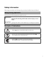
When using your machine, the following safety precautions should be always be followed
Safety During Operation
In this manual, the following important symbols are used:
WARNING:
Ignoring this warning could cause serious injury or even
death.
CAUTION:
Ignoring this caution could cause injury or damage to property.
Examples of Indications
Symbol
means a situation that requires you take care.
Do NOT carry out the operation represented by this symbol
This example means “Do not take apart”.
.
Symbols ● mean you MUST perform this operation.
This example means “You must remove the wall plug”.
i
Safety Information
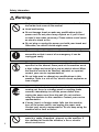
Warnings
• Only connect the machine to the power source described on
the inside front cover of this manual.
• Avoid multi-wiring.
• Do not damage, break or make any modifications to the
power cord. Do not place heavy objects on it, pull it hard
or bend it more than necessary. These actions could cause
an electric shock or fire.
• Do not plug or unplug the power cord with your hands wet.
Otherwise, an electric shock might occur.
• Make sure the wall outlet is near the machine and easily
accessible so that in event of an emergency it can be
unplugged easily.
• Do not remove any covers or screws other than those
specified in this manual. Some parts of the machine are at
a high voltage and could give you an electric shock. When
the machine needs to be checked, adjusted, or repaired,
contact your service representatives.
• Do not take apart or attempt any modifications to this
machine. There is a risk of fire, electric shock, explosion or
loss of sight.
• If the machine looks damaged or breaks down, smoke is
coming out, there is a strange smell or anything looks
unusual, immediately turn off the power switch then
unplug the power cord from the wall. Do not continue
using the machine in this condition. Contact your service
representative.
• If metal, liquid, or foreign matter falls into the machine,
turn off the power switch, and unplug the power cord.
Contact your service representative. Do not keep using the
machine with a fault or defect.
ii
• Do not put any metal objects or containers holding
water(e.g. vases, flowerpots, glasses) on the machine. If
the contents fall inside the machine, a fire or electric
shock could occur.
Safety Information
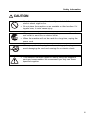
CAUTION
• Keep the machine away from humidity and dust. A fire or an
electric shock might occur.
• Do not place the machine on an unstable or tilted surface. If it
topples over, it could cause injury.
• When you move the machine, unplug the power cord from the
wall outlet to avoid fire or electric shock.
• When the machine will not be used for a long time, unplug the
power cord.
• When you pull out the plug from the socket, grip the plug to
avoid damaging the cord and causing fire or electric shock.
• This machine has been tested for safety using this supplier’s
parts and consumables. We recommend you only use these
specified supplies.
iii
Important Information
Important Information
1. Read all of these instructions and keep them for later reference.
2. Follow all warnings and instructions marked on the machine.
3. Unplug this machine from the wall outlet before cleaning. Do not use liquid cleaners or
aerosol cleaners.
4. Do not use this machine near water.
5. Do not place this machine on an unstable cart, stand, or table. The machine could fall and
suffer serious damage.
6. Slots and openings in the cabinet and the back or bottom are provided for ventilation; to
ensure reliable operation of the machine and protect it from overheating, these openings must
not be blocked or covered. The openings should never be blocked by placing the machine on
a bed, sofa, rug, or other similar surface. This machine should never be placed near or over
a radiator or heat register. This machine should not be placed in a built-in installation unless
proper ventilation is provided.
7. This machine should be operated from the type of power source indicated on the marking
label. If you are not sure of type of power available, contact your dealer or local power
company.
8. This machine is equipped with a 3-wire grounding-type plug, a plug having a third (grouding)
pin. This plug will only fit into a grounding -type outlet. This is a safety feature. If you are
unable to insert the plug into the outlet, contact your electrician to replace your outlet. Do not
defeat the purpose of the grounding-type plug by removing its grounding pin. (This does not
apply in countries in which a 2-wire, nongrounded type of plug is used.)
9. Do not place this machine where the cord will be walked on.
10. If an extension cord is used with this machine, make sure that the total of the ampere ratings
on the devices plugged into the extension cord does not exceed the extension cord ampere
rating. Also make sure that the total of all machines plugged into the wall outlet does not
exceed 15 amperes.
11. Never push objects of any kind into this device through cabinet slots as they may touch
dangerous voltage points or short out parts that could result in a risk of fire or electric shock.
Never spill liquid of any kind on the machine.
12. Except as specifically explained in the operator’s manual, do not attempt to service this device
yourself. Opening or removing those covers that are marked “Do Not Remove” may expose
you to dangerous, voltage points or to other risks. Refer all servicing in those compartment
to service personel.
iv
Important Information
13. Unplug this machine from the wall outlet and refer servicing to qualified service personal
under the following conditions;
A. When the power cord or plug is damaged or frayed.
B. If liquid has been spilled into the machine.
C. If the machine has been exposed to rain or water.
D. If the machine does not operate normally when the operating instructions are followed.
Adjust only those controls that are covered by the operating instructions since improper
adjustment of other controls may result in damage and will often required extensive
work by a qualified technician to restore the machine to normal operation.
E. If the machine has been dropped or the cabinet has been damaged.
F. If the machine exhibits a distinct change in performance, indicating a need for service.
14. Make sure that your wall outlet is close to the machine and is easily accessible.
When you plug the machine into the outlet, make sure the plug is inserted firmly.
15. The main plug on this machine must be used to disconnect main power.
Two kinds of size notation are employed in this manual.
v
How to Read This Manual
How to Read This Manual
In this manual, the following symbols are used:
Warning
This symbol indicates a potentially hazardous situation that might result in death or serious
injury when you misuse the machine without following the instructions under this symbol.
Be sure to read the instructions, all of which are described in the Safety Information section.
Caution
This symbol indicates a potentially hazardous situation that might result in minor or moderate
injury or property damage that does not involve personal injury when you misuse the machine
without following the instructions under this symbol. Be sure to read the instructions, all of
which are described in the Safety Information section.
* The statements above are notes for your safety.
Important
If this instruction is not followed, paper might be misfeed, originals might be damaged, or data might be lost. Be sure to read this.
Note
This symbol indicates precautions for operation, or actions to take after misoperation.
Limitation
This symbol indicates numerical limits, functions that cannot be used together, or
conditions in which a particular function cannot be used.
Reference
This symbol indicates a reference.
{ }
Keys built into the machine’s operation panel.
vi
Table of Contents
Table of Contents
Safety Information ---------------------------------------------------------------------- i
Safety During Operation ----------------------------------------------------------- i
Examples of Indications ------------------------------------------------------------ i
Important Information ---------------------------------------------------------------- iv
How to Read This Manual ----------------------------------------------------------- vi
1. Introduction
Features ----------------------------------------------------------------------------------- 1
Ultra-fast scanning ---------------------------------------------------------------- 1
Simultaneous scanning of both sides of a document --------------------------(Duplex Model only) ----------------------------------------------------------- 1
Direct operation using the buttons on the scanner -----------------------------(Manual Scanning function) ------------------------------------------------------ 1
Large 150-sheet paper capacity -------------------------------------------------- 1
Printing on scanned documents (optional) -------------------------------------- 1
Space-saving design --------------------------------------------------------------- 2
Supports both TWAIN and ISIS ------------------------------------------------ 2
Guide to the Scanner ------------------------------------------------------------------ 3
Understanding the Indicators --------------------------------------------------- 5
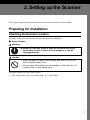
2. Setting up the Scanner
Preparing for Installation ----------------------------------------------------------- 7
Checking the Scanner Location ------------------------------------------------- 7
Connecting to the Host Computer ---------------------------------------------- 10
What is SCSI? ---------------------------------------------------------------------- 10
SCSI Connection Requirements for the Scanner ------------------------- 10
Setting the SCSI ID --------------------------------------------------------------- 11
Connecting the SCSI Cable (No Connection to Other Port) ----------- 11
Connecting the SCSI Cable (Connection to Other Port) ---------------- 12
Connecting the Power Cable ----------------------------------------------------- 13
Turning On/Off the Scanner Power --------------------------------------------- 15
Turning On the Scanner Power ------------------------------------------------ 15
Turning Off the Scanner Power ------------------------------------------------ 15
Initializing the Scanner ------------------------------------------------------------- 16
vii
Table of Contents
3. Setting Originals
Originals ---------------------------------------------------------------------------------- 17
Recommended Sizes and Weights of Originals -------------------------- 17
Difficult to Detect Sizes ----------------------------------------------------------- 18
Original Sizes and Scanning Area -------------------------------------------- 19
Setting Originals ----------------------------------------------------------------------- 20
Setting the Original on the Contact Glass ----------------------------------- 20
Setting the Original in the Auto Document Feeder (ADF) -------------- 21
4. Scanning Originals
General Scanning Method --------------------------------------------------------- 25
Manual Scanning ---------------------------------------------------------------------- 26
5. Troubleshooting
When Scanning Does Not Start --------------------------------------------------- 27
Error Indicators and Solutions ---------------------------------------------------- 28
Procedures to Correct Errors in the ADF ------------------------------------- 29
When an Original is Jammed in
the Auto Document Feeder (ADF) ----------------------------------------- 29
When an Original was Not Output Properly from
the Auto Document Feeder (ADF) ----------------------------------------- 29
When There is a Problem with the Operation of
the Document Table ------------------------------------------------------------ 29
When Characters Printed by the Endorser are Too Light or
the Original Gets Dirty ----------------------------------------------------------- 30
Replacing the Ink Ribbon -------------------------------------------------------- 30
Cleaning the Endorser ------------------------------------------------------------ 32
viii
Table of Contents
6. Appendices
Maintenance ---------------------------------------------------------------------------- 33
Cleaning the Scanner ------------------------------------------------------------ 33
Cleaning the Contact Glass, Slit Glass, White Sheet, and Platen ---------- 34
Cleaning the Feed Roller and Drum ------------------------------------------- 34
Cleaning the White Roller (Duplex Model Only) ---------------------------- 36
Moving the Scanner -------------------------------------------------------------- 38
Carrying the Scanner a Short Distance ---------------------------------------- 39
Shipping the Scanner ------------------------------------------------------------ 39
Disposing of the Scanner ------------------------------------------------------- 39
Options ----------------------------------------------------------------------------------- 40
Image Processing Unit Type A ------------------------------------------------- 40
Red Lamp Unit Type A ----------------------------------------------------------- 40
Endorser Unit Type A(Printing Function) ------------------------------------ 41
Specifications -------------------------------------------------------------------------- 42
Scanner Electrical and Hardware Specifications ------------------------- 42
DIP Switches ---------------------------------------------------------------------------- 43
Functions -------------------------------------------------------------------------------- 44
Preview ------------------------------------------------------------------------------- 44
Scan ----------------------------------------------------------------------------------- 45
Scanning Composition ----------------------------------------------------------- 45
Binary Scanning/Threshold ----------------------------------------------------- 46
Halftone Scanning ---------------------------------------------------------------- 47
Gray Scale Scanning ------------------------------------------------------------- 48
Area Extraction --------------------------------------------------------------------- 49
Section Area (Multi-area Settings) -------------------------------------------- 50
Auto Photo/Letter ------------------------------------------------------------------ 51
Resolution --------------------------------------------------------------------------- 52
Brightness --------------------------------------------------------------------------- 53
Contrast ------------------------------------------------------------------------------ 53
Gamma Correction ---------------------------------------------------------------- 54
Binary Filters ------------------------------------------------------------------------ 55
Parameter Download ------------------------------------------------------------- 55
Document Size Detection ------------------------------------------------------- 56
Erase Background ---------------------------------------------------------------- 57
Index --------------------------------------------------------------------------------------- 58
ix
x
1. Introduction
Features
This section describes the features of this scanner.
Ultra-fast scanning
When scanning A4K (8½” × 11”K), monochrome at 200dpi, this scanner can scan 55 (57)
images/minute. When scanning A4K (8½” × 11”K), monochrome at 400dpi, this scanner can
scan 31 (32) images/minute. During double-sided scanning, when scanning A4K (8½” ×
11”K), monochrome at 200dpi, this scanner can scan 86 (88) images/minute.
*
When using the Auto Document Feeder (ADF) in binary scanning, these speeds apply to
the second and subsequent sheets.
Simultaneous scanning of both sides of a document
Model only)
(Duplex
If a document consists of individual, separate sheets, both sides of each sheet can be scanned
simultaneously. This capability eliminates the bother of having to flip document sheets over.
Direct operation using the buttons on the scanner
(Manual Scanning function)
If using a driver that supports the Manual Scanning function, scanning can be initiated by
pressing the {Start} button on the scanner. This function is useful when scanning a document
that needs to be set in place for each scan.
Large 150-sheet paper capacity
Up to 150 sheets* can be placed in the scanner’s Auto Document Feeder (ADF).
* A4 (64g/m2) or 8½” × 11” (20lb)
Printing on scanned documents (optional)
The Endorser Unit Type A is provided as an optional mechanism that prints a symbol or the
number of documents that have been scanned by the Auto Document Feeder (ADF). This
capability is useful for referencing scanned data or confirming that a document has been scanned.
1
1. Introduction
Space-saving design
This scanner is designed in a “wingless” style, in which there are no protruding elements, such as
a document tray. This design allows the scanner to be set up next to a wall, and permits office
space to be used more effectively.
Supports both TWAIN and ISIS
The scanner supports both the standard TWAIN and the newer ISIS driver, allowing the scanner
to function with a wide range of software.
2
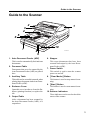
Guide to the Scanner
Guide to the Scanner
3
4
6
2
1
5
7
10
TH2H010E
8
9
1. Auto Document Feeder (ADF)
This is used to automatically feed and scan
documents.
2. Document Table
Documents that are to be scanned by the
Auto Document Feeder (ADF) are placed
here.
3. Auxiliary Table
This table can be extended outwards when
placing large documents in the Auto Document Feeder (ADF).
4. Endorser Cover
Open this cover in order to clean the Endorser (printing function) or replace the
ink.
5. Output Table
6. Stopper
This stops documents that have been
scanned and output by the Auto Document Feeder (ADF).
7. Power Switch
This switch is used to turn the scanner
power on and off.
8. {Clear Modes} Button
This button is used to stop manual scanning.
9. {Start} Button
This button is used to start manual scanning.
10. Scanner Indicators
These indicators can be used to check the
status of the scanner.
After a document has been scanned by
the Auto Document Feeder (ADF), it is
output here.
3
1. Introduction
TH2H020E
3
1
2
4
1. White Sheet
This presses the document down on the
contact glass.
2. Contact Glass
This is where the document is placed.
3. ADF Cover
Open this cover to clear paper jams, etc.
4. Power Connector
Connect the power cable here.
5. Rotary Switch
This switch is used to set the SCSI ID.
6. SCSI Connector
Connect the SCSI interface cable here.
4
5
6
78 9
7. Interface for Reverse Side Scanning
This is an extension interface for reverse
side scanning. (Duplex Model only)
8. DIP Switches
These switches are used to set the operating mode.
9. Reset Switch
This switch resets the scanner as if the
power had been turned off and then back
on again. This switch is used to make
new DIP switch and rotary switch settings valid.
Guide to the Scanner
Understanding the Indicators
The scanner has the following indicators:
TH2H030E
1:
2:
3:
4:
Power On
Machine Busy
Document in Place
Error
1
3
2
4
When the scanner is in a normal operating state, the indicators will light in one of the combinations shown below. If the indicators light in any other pattern, an error has occurred. Refer to p.
28, “Error Indicators and Solutions.”
Description
❍
❍
❍
❍
❍
●
●
●
❍
●
❍
●
❍
❍
●
●
❍
❍
❍
●
❍
✕
●
●
✕
●
●
●
When the power has just been turned on, or the
Reset switch has been pressed (This combination
is displayed only for a few seconds.)
When there is no document in the Auto Document Feeder, and no document is being scanned
When there is a document in the Auto Document
Feeder, but the document is not being scanned
When scanned data is being transferred (and there
is no document in the ADF)
When scanned data is being transferred (and there
is a document in the ADF)
When the scanner is ready for manual scanning
When the scanner is ready by Low Power Mode
❍ : On
✕ : Flashing
● : Off
5
1. Introduction
6
2. Setting up the Scanner
This chapter explains the preparations that are necessary in order to use the scanner.
Preparing for Installation
Checking the Scanner Location
Set up the scanner in a location that satisfies the following conditions:
❖ Setup location
Warning:
• Make sure the wall outlet is near the machine and easily
accessible so that in event of an emergency it can be
unplugged easily.
Caution:
• Keep the machine away from humidity and dust. A fire or an
electric shock might occur.
• Do not place the machine on an unstable or tilted surface. If it
topples over, it could cause injury.
Set up the scanner on a flat, stable surface.
•
The surface must be level to within 5mm ( 0.2”) on all sides.
7
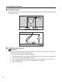
2. Setting up the Scanner
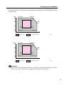
❖ Installation space
Set up the scanner in a location where there is enough space to provide the clearance shown
in the figure below.
❖ Installation environment
Important
❒ Do not set up the scanner in any of the types of locations listed below. Doing so
could cause the scanner to malfunction.
• In a location exposed to direct sunlight
• In a location where the scanner will be subjected to blowing air or radiant heat,
such as near an air conditioner or heater
• In a location near other electronic devices, such as a radio or television set
• In a location subject to extreme temperatures or humidity
• Near a humidifier
8
Preparing for Installation
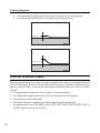
Set up the scanner in a location where the temperature and humidity will fall within the ranges
shown below.
%RH
80
27°C 80%
10°C 80%
25°C
70%
15°C
70%
60
32°C
54%
40
15°C
30%
25°C
30%
32°C 15%
10°C 15%
20
Usable range
%RH
80
°C
30
20
10
Recommended range
TH2H061E
80.6°F 80%
50°F 80%
77°F
70%
59°F
70%
60
89.6°F
54%
40
77°F
30%
59°F
30%
89.6°F 15%
50°F 15%
20
50
60
Usable range
70
80
90
°F
Recommended range
TH2H070E
Important
❒ Save the box and cushioning material in which the scanner was packed so that they
can be used if it is necessary to transport the scanner in the future.
9
2. Setting up the Scanner
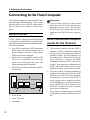
Connecting to the Host Computer
This scanner connects to a host personal computer through a SCSI interface. This section
provides an overview of SCSI, and explains
how to connect the scanner to a host computer.
What is SCSI?
“SCSI” (Small Computer System Interface)
is an interface standard that is used for highspeed data transfer between a peripheral device
and a host computer.
SCSI Connection Requirements for the Scanner
•
In a SCSI connection, ANSI-compliant
SCSI cables are used to connect one or
more peripheral devices in daisy chain
fashion to the host computer.
•
•
Each device is assigned a unique SCSI
ID (0 to 7), which must be set for the
device before turning on the power and
before turning on the computer.
•
The last device in the daisy chain requires
a terminator.
This scanner complies with the SCSI-2
standard. SCSI-1-compliant peripheral
devices can also be connected and used
with this scanner. The SCSI interface on
the scanner has a 50-pin half-pitch (pin
type) connector. Connect an ANSIcompliant shielded SCSI-2 cable to the
scanner. Note that some combinations of
cables and SCSI boards will not work
together properly, so check this carefully.
•
If you are using a SCSI board and driver
software that supports SCAM, the SCSI
ID of this scanner will be set automatically, so there is no need to set the ID. If
you are using a driver that does not have
a SCAM function, it will be necessary to
set the SCSI ID for the scanner if the
SCSI ID is identical to that of another
device that is connected.
•
The scanner’s terminator can be enabled
or disabled by turning a DIP switch on or
off.
1: SCSI cables
2: Up to 7 devices
3: Terminator
10
Important
❒ If two or more devices in a daisy chain
share the same SCSI ID, misoperation
and data loss may result. Set a unique
SCSI ID for this scanner that does not
duplicate the SCSI ID of any other device.
Connecting to the Host Computer
Important
❒ The total length of the SCSI cables, including the length of the cable inside
the personal computer, should be no
more than 3m (9.8 ft.) when using Fast
SCSI, and no more than 6m (19.7 ft.)
when using non-Fast SCSI.
❒ Some combinations of SCSI boards and
peripheral devices that are connected
simultaneously may not work together
properly.
Connecting the SCSI Cable
(No Connection to Other Port)
A
Turn off the host computer and all
peripheral devices that will be connected through the SCSI interface.
B
Use SCSI cables to connect the personal computer and the peripheral devices in daisy chain fashion, with this
scanner at the end of the daisy chain.
(Use either of the two SCSI connectors on the scanner.)
C
Set DIP switch 3 to off.
This enables the scanner’s internal terminator. For details on the functions of the
DIP switches, refer to P.43, “DIP
Switches.”
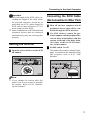
Setting the SCSI ID
A
Turn the rotary switch to set the SCSI
ID number.
Note
❒ If you change the setting while the
power is on, it is necessary to initialize
the scanner. Refer to P.16, “Initializing the Scanner.”
11
2. Setting up the Scanner
Connecting the SCSI Cable
(Connection to Other Port)
12
A
Turn off the host computer and all peripheral devices that will be connected
through the SCSI interface.
B
Use SCSI cables to connect the personal computer and the peripheral devices in daisy chain fashion, with this
scanner in the middle of the daisy
chain.
C
Set DIP switch 3 to on.
This disables the scanner’s internal terminator. For details on the functions of the
DIP switches, refer to P.43, “DIP
Switches.”
Connecting the Power Cable
Connecting the Power Cable
This section explains how to connect the power cable to the scanner.
Warning
• Only connect the machine to the power source described
on the inside front cover of this manual.
• Avoid multi-wiring.
• Do not damage, break or make any modifications to the
power cord. Do not place heavy objects on it, pull it hard
or bend it more than necessary. These actions could cause
an electric shock or fire.
• Do not plug or unplug the power cord with your hands wet.
Otherwise, an electric shock might occur.
Warning
• Be sure to ground the scanner. Failure to ground the
scanner could result in fire or electric shock. If there is no
ground connection available, consult your dealer.
Caution
• When you pull out the plug from the socket, grip the plug to
avoid damaging the cord and causing fire or electric shock.
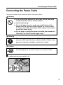
A
Confirm that the power switch is off.
13
2. Setting up the Scanner
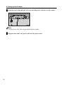
B
Push the power cable plug all of the way into the power connector on the scanner.
Note
❒ Use the power cable that was provided with this scanner.
C
14
Plug the other end of the power cable into the power outlet.
Turning On/Off the Scanner Power
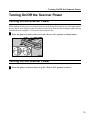
Turning On/Off the Scanner Power
Turning On the Scanner Power
When turning on the power, turn on each device in the daisy chain one by one, starting from the
device that is at the opposite end of the daisy chain away from the host computer and working
towards the host computer. Turn on the host computer last.
A
Press the power switch so that it is in the “Power On” position as shown below.
Turning Off the Scanner Power
A
Press the power switch so that it is in the “Power Off” position as above.
15
2. Setting up the Scanner
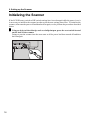
Initializing the Scanner
If the SCSI ID rotary switch or DIP switch settings have been changed while the power is on, it
is necessary to initialize the scanner in order to put the new settings into effect. To initialize the
scanner, either turn the power off and then back on again, or else perform the procedure described
below:
A
16
Using an object with a thin tip, such as a ballpoint pen, press the reset switch located
on the back of the scanner.
Doing so puts the scanner into the same state as if the power had been turned off and then
back on again.
3. Setting Originals
This section explains how to set originals that are to be scanned in the scanner.
Originals can be set either on the contact glass or in the Auto Document Feeder (ADF). The Auto
Document Feeder (ADF) is useful when you want to scan multiple originals consecutively.
Originals
Recommended Sizes and Weights of Originals
Where original is set
Original size
Original weight
Contact glass
Up to A3
---
Up to 11" x 17"
Auto Document Feeder (ADF) Maximum:A3K
Minimum:69 x 120mm
Maximum:11” x 17”K
Minimum:2.75” x 4.75”
41 ~ 128g/m 2
11 ~ 34lb
❖ Originals that cannot be set in the Auto Document Feeder (ADF)
Setting an original that falls in one of the following categories in the Auto Document Feeder
(ADF) could result in a paper jam or in damage to the original. Such originals should be
placed on the contact glass.
• An original that does not fall within the “Recommended Sizes and Weights of Originals”
• An original that includes staples, paper clips, glue, or other adhesives
• An original that has holes or is torn
• An original that is warped, creased, or wrinkled
• An original that is pasted together
• An original that has some sort of surface treatment, including thermal paper, art board,
silver paper, carbon paper, or conductive paper.
• An original that has index tabs, stick-on notes, or other protrusions
• An original on paper that does not slide easily, such as tracing paper
• An original on thin, fragile paper
• An original that is not of a suitable thickness, such as a postcard
⇒ “Recommended Sizes and Weights of Originals”
• An original that is bound, such as a book
17
3. Setting Originals
•
•
An original that is highly transparent, such as transparencies or tracing paper
An original that has markedly curled edges, such as shown below
5mm(0.2") or more
10mm(0.4") or more
Difficult to Detect Sizes
When the optional Image Processing Unit Type A is installed, the scanner can automatically detect
the size of an original. However, the sizes of the following types of originals are difficult to detect
properly, even if using a scanner driver that supports automatic detection of the size of the
original:
18
•
An original that has index tabs, stick-on notes, or other protrusions
•
An original that is highly transparent, such as transparencies or tracing paper
•
Documents on a dark background
•
Documents with text, illustrations, or filled in portions on the leading edge
•
An original that is not A3K, B4K, A4K, B5K, A5K, B6K, A6K, DLTK, LTK, or
HLTK (when set on the contact glass)
Originals
Original sizes that can be detected automatically
Original size
Where original
Paper sizes used in Japan
Paper sizes used overseas
A3 B 4 A4 A4 B 5 B 5 A5 A5 B 6 B 6 A6
K K K L K L K L K L K
Irregular sizes
11”x17” 8½”x14” 8½”x11” 8½”x5½” 8½”x5½” 8½”x5½”
(DTL)K (LG) K (LT) K (LT) L (HLT) K (HLT) K
is placed
Contact glass
✔ ✔ ✔
✔
✔
Auto Document
Feeder (ADF)
✔
✔
✔
✔ ✔ ✔ ✔ ✔ ✔ ✔ ✔ ✔ ✔ ✔
✔
✔
✔
✔
✔
✔
✔
✔
✔
Original Sizes and Scanning Area
❖ Contact glass
❖ Auto Document Feeder (ADF)
19
3. Setting Originals
Setting Originals
Setting the Original on the Contact Glass
Caution:
• Be careful not to pinch your fingers when closing the Auto
Document Feeder (ADF).
A
Open the Auto Document Feeder (ADF).
B
With the side to be scanned facing down, place the original on the contact glass, and
align it with the home position and scale.
1: Home position
2: Scale
Important
❒ Do not press down on the contact glass. Strong localized pressure on the contact glass
could cause it to break.
C
20
Gently close the Auto Document Feeder (ADF).
Setting Originals
Setting the Original in the Auto Document Feeder (ADF)
Note
❒ Do not set originals in the Auto Document Feeder (ADF) in excess of the upper limit mark.
(Stacked height: Not more than 15mm (0.6"))
❒ The number of sheets that can be set in the Auto Document Feeder (ADF) at one time
depends on the size and weight (thickness) of the originals. Use the following table as a
guide:
Stacked height
15mm
(0.6")
Weight
105g/m2
(24lb)
64g/m2
(20lb)
Size
Number of
sheets that can
be set
A4, A5,
(LT, HLT)
110
A3
(DLT)
80
A4, A5, A3
(LT, HLT, DLT)
150
Limitation
❒ If there is a darkly colored image within about 40mm of the leading edge at the center of the
original, the scanner may not be able to detect the presence of the original. In this case,
either add a blank white sheet as the first page of the original, or place the original on the
contact glass.
A Align the originals on the ADF.
•
•
When scanning large originals, pull out the auxiliary table.
Adjust the stopper on the output table according to the size of the originals.
1: Auxiliary table
2: Stopper
21
3. Setting Originals
Note
❒ When scanning an original that is A5K(HLTK) size or smaller, pull the stopper out of the
output table, turn it around, slide it back into the table, and adjust the position. (Refer to the
diagram below.)
Important
❒ When the stopper is extended, do not grasp the stopper when opening or closing the Auto
Document Feeder (ADF).
B
Put the originals in order. If they are to be scanned in page sequence, put them in
order as illustrated below.
Simplex scanning
Duplex scanning
22
Setting Originals
C
Fan the sheets, and then line up their edges.
D
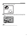
With the first page facing up on top, place the originals in the Auto Document Feeder
(ADF), and adjust the positions of the guides so that they touch the edges of the
original.
1: Guides
Note
❒ Make sure the Auto Document Feeder (ADF) is closed.
23
3. Setting Originals
24
4. Scanning Originals
General Scanning Method
Scanning of an original is initiated by software that is TWAIN or ISIS compatible. The method
of operation depends on the software. For details, refer to the manual that was supplied with your
software.
Limitation
❒ When using double-sided scanning, if the leading edge of the reverse side of the document is
dark, the scanned image may appear whitish.
25
4. Scanning Originals
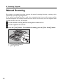
Manual Scanning
By setting up a scanner driver that supports the manual scanning function, scanning can be
initiated by pressing the {Start} button.
If the manual scanning function is used, then communications between the scanner and the
personal computer are no longer needed in cases where it is necessary to set the original in the
scanner one sheet at a time, for example.
A
B
C
Set the manual scanning function through the scanner driver.
Set the original in the scanner.
Press the {Start} button. To end manual scanning, press the {Clear Modes} button.
TH2H220E
1: {Clear Modes} Button
2: {Start} Button
26
5. Troubleshooting
When Scanning Does not Start
If scanning does not start, check the following:
Item to check
Action
Is the power on?
Turn on the power.
Is the SCSI ID set properly?
If there are any other SCSI devices
connected, the host computer may not be
able to recognize the scanner if it has the
same SCSI ID as another device. Refer to
P.11, “Setting the SCSI ID,” and set a
unique SCSI ID for the scanner.
Are the DIP switches set properly?
The correct DIP switch settings depend on
whether this scanner is the last device in the
SCSI daisy chain. Refer to P.11,
“Connecting the SCSI Cable,” and set the
DIP switches properly.
Are the SCSI cables connected securey? If any cables are disconnected, connect
them.
Are the indicators on or flashing?
The nature of an error can be determined
according to the pattern in which the four
indicators are on or flashing. Refer to P.28,
“Error Indicators and Solutions.”
Is the scanner driver selected properly?
For details on scanner driver setup, refer to
the manual or help information for your
scanner driver.
Are the software settings correct?
For details on software settings, refer to the
manual or help information for your
software.
27
5. Troubleshooting
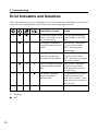
Error Indicators and Solutions
When the indicators are on or flashing in any of the following combinations, an error has
occurred. After confirming the nature of the error, take the appropriate action.
Description of error
❍
●
●
❍
The Auto Document Feeder Close the Auto Document
(ADF) or the ADF cover is Feeder (ADF) or the ADF
not closed properly.
cover.
❍
●
✕
❍
❍
●
❍
❍
❍
●
✕
✕
✕
✕
❍
●
✕
✕
✕
✕
An original is jammed in
Refer to P.29, “Procedures
the Auto Document Feeder to Correct Errors in the
(ADF).
ADF,” and remove the
jammed paper.
An original was not output Refer to P.29, “Procedures
properly from the Auto
to Correct Errors in the
Document Feeder (ADF). ADF,” and remove the paper
that was not output.
There is a problem with the Refer to P.29, “Procedures
operation of the document to Correct Errors in the
table.
ADF” and open and close
the ADF cover.
The Endorser (printing
Try opening and closing the
function) may have
Auto Document Feeder
malfunctioned.
(ADF) several times. If the
same error occurs, contact a
service center.
System error
Contact a service center.
❍ : On
✕ : Flashing
● : Off
28
Action
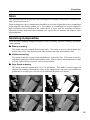
Procedures to Correct Errors in the ADF
Procedures to Correct Errors in the ADF
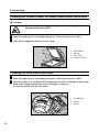
When an Original is Jammed
When an Original was Not Out-
in the Auto Document Feeder
(ADF)
put Properly from the Auto Document Feeder (ADF)
A
B
A
B
Open the ADF cover.
Turn the drum knob in the direction
indicated by the arrow.
1: Knob
2: Feed roller
C
Remove the original from the output
table.
Note
❒ If the leading edge of a original is
jammed in the feed rollers, grasp the
leading edge of the original and gently
pull it out in the direction of the ADF
cover.
Open the ADF cover.
Pull out the original.
WhenThere is a Problem with
the Operation of the Document Table
A
Remove the original from the Auto
Document Feeder (ADF).
B
Open the ADF cover.
C
Close the ADF cover.
29
5. Troubleshooting
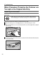
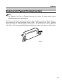
When Characters Printed by the Endorser are
Too Light or the Original Gets Dirty
Replacing the Ink Ribbon
Caution:
• When you pull out the plug from the socket, grip the plug to
avoid damaging the cord and causing fire or electric shock.
Replace the ink ribbon if the Endorser’s printing becomes too light.
A
B
C
30
Turn off scanner power, and unplug the power cable from the power outlet.
Flip open the Endorser cover (located towards the rear of the output table), and pull
the cover out.
Grasp the green portion of the Endorser, and turn it in the direction indicated by the
arrow until it clicks.
When Characters Printed by the Endorser are Too Light
or the Original Gets Dirty
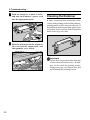
D
Raise the rear portion of the Endorser,
and then pull the Endorser out.
Important
❒ Do not pull on the Endorser’s cord.
E
F
Gently press the old ink ribbon cartridge down ➀ , and then pull it out ➁ .
G
Push a new ink ribbon cartridge into
the Endorser.
Place the Endorser down with the
printing section facing up.
H
Align the endorser with the hooks on
the scanner as shown in the diagram.
Important
❒ Do not touch the printing section of the
Endorser. Doing so may get your fingers dirty, and could damage the printing
section.
31
5. Troubleshooting
I
Push the Endorser in until it clicks,
and tuck the Endorser’s power cord
into the appropriate hook.
Cleaning the Endorser
If paper scraps and dust accumulate in the
vicinity of the printing section of the Endorser,
printing quality will be adversely affected. If
the printing section becomes dirty, gently wipe
the portion shown in white in the illustration
below with a dry, soft cloth.
J
Slide the protrusion on the bottom of
the cover into the output table, and
then push the cover closed.
Important
❒ Do not wipe any portion other than that
which is shown in white above. In addition, do not touch the printing section.
Doing so may get your fingers dirty, and
could damage the printing section.
32
6. Appendices
Maintenance
Cleaning the Scanner
Warning:
• Do not remove any covers or screws other than those
specified in this manual. Some parts of the machine are at a
high voltage and could give you an electric shock. When the
machine needs to be checked, adjusted, or repaired,
contact your service representatives.
• Do not take apart or attempt any modifications to this
machine. There is a risk of fire, electric shock, explosion or
loss of sight.
Caution:
• When you pull out the plug from the socket, grip the plug to
avoid damaging the cord and causing fire or electric shock.
Periodic cleaning is required in order to maintain this scanner in good condition.
First, wipe away any dirt with a dry, soft cloth. If the dirt cannot be removed with a dry cloth,
moisten a soft cloth with water, wring it out thoroughly, and then wipe away the dirt. If water is
not sufficient to remove the dirt, wipe off the dirt with a mild detergent solution, then wipe the
detergent away with water, and then wipe the area with a dry cloth until all moisture has been
removed.
Important
❒ Do not use volatile chemicals such as benzene or paint thinner to clean the scanner, and do
not spray insect sprays, etc., on the scanner. Such chemicals could deform, discolor, or
crack scanner components.
❒ If there is any dust or dirt inside the scanner, wipe it away with a dry, clean cloth.
33
6. Appendices
Cleaning the Contact Glass, Slit Glass, White Sheet, and Platen
Caution:
• Be careful not to pinch your fingers when closing the Auto
Document Feeder (ADF).
A
B
Turn off scanner power, and unplug the power cable from the power outlet.
Wipe these components with a soft, dry cloth.
1:
2:
3:
4:
White Sheet
Platen
Slit Glass
Contact Glass
Cleaning the Feed Roller and Drum
A
B
Turn off scanner power, and unplug the power cable from the power outlet.
Open the ADF cover, and then while turning the feed roller and drum by hand, wipe
them with a damp cloth that has been thoroughly wrung out.
To turn the drum, turn the blue knob.
1: Feed Roller
2: Drum
3: Knob
34
Maintenance
Note
❒ Always clean the feed roller after scanning an original that was written in pencil or with
some other material that is not solidly fixed on the paper.
If you do not clean the feed roller, it may dirty the next original that is scanned.
35
6. Appendices
Cleaning the White Roller (Duplex Model Only)
If white stripes (in the normal paper direction) appear in the image from the reverse side of the
original when a double-sided document is scanned, clean the white roller according to the procedure
described below.
A
B
C
Turn off scanner power, and unplug the power cable from the power outlet.
Open the Auto Document Feeder (ADF), and pull off the white sheet (which is held in
place by cellophane tape).
While turning the blue knob on the drum in the direction indicated by the arrow, wipe
the white roller with a damp cloth that has been thoroughly wrung out.
1: White roller
2: Drum
D
36
Place the white sheet on the contact glass with the reverse side facing up.
Maintenance
E
Align the arrow on the reverse side of the white sheet with the document home
position.
Note
❒ Make sure that the white sheet does not lie on the scales.
1: Home position
2: Scales
F
Gently close the Auto Document Feeder (ADF), and press it down on it firmly.
G
Open the Auto Document Feeder (ADF) again, and rub a cloth against the entire
surface of the white sheet.
37
6. Appendices
Moving the Scanner
Caution:
• The scanner weighs a maximum 29kg. When moving the
scanner, always hold it with the Auto Document Feeder
(ADF) against yourself, and lift it up slowly so as not to
strain yourself. Trying to lift the scanner even though it is
too heavy for you, or handling the scanner carelessly and
dropping it can result in injury.
• When it is necessary to move the scanner a long distance,
contact a service center.
Caution:
• When you move the machine, unplug the power cord from the
wall outlet to avoid fire or electric shock.
• When the machine will not be used for a long time, unplug the
power cord.
Caution:
• When you pull out the plug from the socket, grip the plug to
avoid damaging the cord and causing fire or electric shock.
38
•
The minimum time for which will be kept inventories of replacement parts needed for
maintenance services is seven years from the date that a model goes out of production.
Accordingly, after this period has elapsed, it may not be possible to accept a unit for repairs.
•
If you contact a service center, they will prepare the scanner for safe shipment for you.
However, you will be responsible for the actual packing and shipping of the scanner.
Maintenance
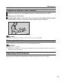
Carrying the Scanner a Short Distance
A
B
C
Turn off scanner power, and unplug the power cable from the power outlet.
Disconnect the SCSI cables.
Grasping the scanner on the sides, above the bottom, and with the Auto Document
Feeder (ADF) closest to yourself, carry the scanner to its new location.
Important
❒ When carrying the scanner, try to keep it as level as possible.
Shipping the Scanner
When shipping the scanner, pack it in its original shipping carton.
Important
❒ Disconnect all cables.
❒ Because the scanner is a precision instrument, pack it carefully so that it will not be
damaged while in transit.
Disposing of the Scanner
When you wish to dispose of your scanner, contact your dealer or a service center.
39
6. Appendices
Options
This section describes options that are sold separately.
Image Processing Unit Type A
Note
❒ The Image Processing Unit Type A is an option.
If this option is used, the following image processing features become possible:
Dynamic Threshold
This function automatically determines a suitable threshold value on the basis of the brightness
of the original, and converts the scanned image to binary data.
Limitation
❒ During double-sided scanning, this function is valid only for the front side of the original.
Auto Photo/Letter
This function automatically identifies the text portions of an original and the photographic
portions, and scans each in a suitable scan mode.
Limitation
❒ During double-sided scanning, this function is valid only for the front side of the original.
Document Size Detection
This function automatically detects the width of an original, and sends the information to the
host computer.
Section Area
This function selects an area within an original and sets scanning conditions for that area.
Limitation
❒ During double-sided scanning, this function is valid only for the front side of the original.
For details on installing the Image Processing Unit Type A, refer to the supplement, “Setting up
the Image Processing Unit Type A.”
Red Lamp Unit Type A
Note
❒ The Red Lamp Unit Type A is an option. The Red Lamp Unit Type A can be used to
eliminate red elements, such as marker or red pen. To install or replace the Red Lamp Unit
Type A, contact your dealer or a service center.
40
Options
Endorser Unit Type A (Printing Function)
Note
❒ The Endorser Unit Type A (Printing Function) is an option for some models, and is
standard equipment on other models.
The Endorser Unit Type A (printing function) can print a symbol or number on originals that have
been scanned by the Auto Document Feeder (ADF). The Endorser Unit Type A (printing
function) settings are made through the scanner driver. For details on how to set the Endorser
Unit Type A, refer to the manual and help provided for the scanner driver that you will be using.
41
6. Appendices
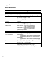
Specifications
Scanner Electrical and Hardware Specifications
42
Type
Desktop flatbed scanner
Scanning methods
Fixed original scanning and moving original scanning
Scanning area
Main-direction: 298mm (11.7”) max.
Sub-direction: 432mm (17”) max.
Resolution
Main-scanning: 400dpi
Sub-scanning: 400dpi
Gray scale
8 bits/pixel
Scanning time
0.65 seconds (A4K/200dpi/binary)
0.62 seconds (LTK/200dpi/binary)
Scanning speed
Simplex Model: 55ppm (A4K/200dpi/binary)
57ppm (LTK/200dpi/binary)
Duplex Model: 86ipm (A4K/200dpi/binary)
88ipm (LTK/200dpi/binary)
*ipm: images per minute
Warm-up time
Max. 15 seconds
Interface
SCSI-2 50-pin half-pitch (pin type) x 2
Power consumption
Simplex Model:
50W maximum when in standby (options installed)
90W maximum when operating (options installed)
Duplex Model:
80W maximum when in standby (options installed)
120W maximum when operating (options installed)
Size
470mm (W) x 677mm (D) x 278mm (H)
18.5” (W) x 26.7” (D) x 10.9” (H)
Weight
Simplex Model: Approximately 25kg (55.1lb)
Duplex Model: Approximately 26kg (63.9lb)
(Add 1kg (4.4lb) when the Endorser Unit Type A is installed.)
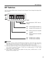
DIP Switches
DIP Switches
Only the settings of DIP switches 1 through 3 can be changed. Do not change the settings of the
other switches.
Leave these set to “OFF;” do not
change.
OFF: Internal SCSI terminator on
ON: Internal SCSI terminator off
OFF: SCSI synchronous transfer
ON:
enabled
SCSI synchronous transfer
disabled
OFF: SCAM function enabled
ON: SCAM function disabled
Important
❒ If multiple scanners with the SCAM function enabled are connected on the same daisy
chain, the host will not be able to recognize the IDs. In this case, set DIP switch 1 to
“ON”(SCAM function disabled), and set the SCSI ID with the rotary switch.
❒ If the daisy chain is too long, or if a nonstandard SCSI cable is used, misoperation may
occur during synchronous transfer. In this case, set DIP switch 2 to “ON” (SCSI
synchronous transfer disabled).
❒ If this scanner is connected in the middle of a daisy chain, set DIP switch 3 to “ON”
(internal SCSI terminator off).
43
6. Appendices
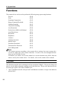
Functions
The scanner driver can be used to perform the following image processing functions:
Preview
(P.44)
Scan
(P.45)
Scanning Composition
(P.45)
Binary Scanning/Threshold
(P.46)
Halftone Scanning
(P.47)
Gray Scale Scanning
(P.48)
Area Extraction
(P.49)
Section Area (Multi-area Settings)
(P.50)
Auto Photo/Letter
(P.51)
Resolution
(P.52)
Brightness
(P.53)
Contrast
(P.53)
Gamma Correction
(P.54)
Binary Filters
(P.55)
Parameter Download
(P.55)
Document Size Detection
(P.56)
Erase Background
(P.57)
Note
❒ The scanner operates according to the scanner driver settings, but some scanner drivers do not support all of the scanner functions. In such a case, the unsupported functions are not available for use.
In addition, the names used in this manual for certain functions may differ from the
names used by the scanner driver. For details, refer to the scanner driver manual.
Preview
This function scans the entire scanning area at low resolution (100dpi*). The preview image can
then be viewed while setting the scanning area for the final scan. The preview function can also
be used to get a quick view of the scannable area.
*
44
“dpi” is an abbreviation for “dots per inch,” and indicates resolution. A larger value indicates
greater detail.
Functions
Scan
This function scans an original once the scanning area, scanning composition, resolution, and
other values have been set.
When setting these values, consideration should be given to the original that is to be scanned and
to the output device (display, printer, etc.). For example, it is meaningless to scan an original at
high resolution if the resolution of the output device is lower than the scanning resolution,
especially because high-resolution scanning uses a great deal of memory and requires more
processing time.
Scanning Composition
There are three scanning composition modes: binary scanning, halftone scanning, and multivalue scanning.
❖ Binary scanning
This mode scans the original in black and white. This mode is used to scan originals that
consist only of text, line drawings, and other elements that lack intermediate colors.
❖ Halftone scanning
This mode scans the original in pseudo-halftones created by dots. This mode is used to
output an original that contains intermediate colors, such as a photo, on an output device that
can only express binary per pixel, such as a laser printer.
❖ Gray Scale scanning
This mode scans the original with 16 or 256 gradations. This mode is used to output an
original that contains intermediate colors on an output device that can express different
gradations for a single pixel, such as a Dye Sublimation printer or a display.
Original
Binary
Halftone
Gray Scale
45
6. Appendices
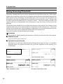
Binary Scanning/Threshold
The binary scanning function converts the original into black and white image data. If the original
contains any intermediate colors, they are compared with the threshold value and determined to be
either black or white accordingly. The threshold value can be set to any of 255 gradations; any
intermediate colors that are brighter than the threshold value are scanned as “white,” and those that
are darker than the threshold value are scanned as “black.” This mode should be used to scan
originals that have no intermediate colors and consist of only two colors, such as text or line
drawings.
The threshold value should be set according to the intensity of the original. For example, setting
a high threshold value when scanning faint text will produce text that is much clearer. Conversely,
setting a low threshold value when scanning an original that is on a colored background (such as
text on colored paper) will eliminate the background color from the scan.
There are two modes for the threshold value setting:
Limitation
❒ During double-sided scanning, this function is valid only for the front side of the original.
❖ Standard mode
Any one of 255 values can be set.
❖ Dynamic threshold mode
This function is valid only when the optional Image Processing Unit Type A is installed.
With this mode, the optimal threshold value (given the brightness of the original) is set
automatically.
46
Original
Low threshold value
High threshold value
Dynamic threshold mode
Functions
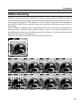
Halftone Scanning
Halftone scanning converts the original into an image consisting of pseudo-halftones produced
by dot shading (in which shading is achieved through combinations of black and white dots, as
in newspaper photographs). This function is used to output an original that has intermediate
tones, such as a photo, on an output device that can only produce monochrome output, such as a
laser printer.
Because halftone scanning expresses pseudo-halftones, it does not require as much memory,
making it effective for filing a large volume of images. There are eleven types of halftones (ten
dot shading patterns and one error diffusion pattern) for selection. It is also possible to scan and
download your own dot shading patterns.
The names in parentheses indicate the names under the ISIS driver.
Original
8x4
45°
16 x 16
90°
6x6
90°
8x8
90°
4x4
Spiral
8 x 8 Bayer
16 x 8
45°
Error diffuson
47
6. Appendices
70 LPI
95 LPI
180 LPI
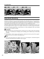
Gray Scale Scanning
Glay Scale scanning converts an original into image data consisting of 4-bit or 8-bit gradations.
Four bits can express 16 gradations, and eight bits can express 256 gradations. This function is
used to output an original that contains intermediate tones on an output device that can express
intermediate tones for a single pixel, such as a display or a Dye Sublimation printer.
Although a higher number of bits produces higher image quality, it is important to remember that
the processing time will be longer. For example, when an area is scanned using the 8-bit multiscan mode, it requires eight times as much memory as when scanning the same area through
binary scanning or halftone scanning.
Limitation
❒ When this function is used during duplex scanning, there are limits on the front and image
data size: 3.6 million bytes with gray scale scanning, and 4 million bytes with binary
scanning
❒ During double-sided scanning, this function is valid only for the front side of the original.
data size for the reverse side is 360 million bytes.
Note
❒ When using this function, the image on the reverse side might be scanned through the
document, depending on the condition of the original.
Original
48
4-bit image
8-bit image
Functions
Area Extraction
This function extracts and scans a specified rectangular area within a scanning area.
For example, to scan just the photograph portion of the original shown below, specify the area
where the photograph is located. The rectangular area is specified by specifying the coordinates
of the upper left corner of the rectangle, and the vertical and horizontal lengths.
Specified area
Original
k
Scanned result
Scanned image
49
6. Appendices
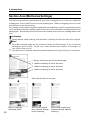
Section Area (Multi-area Settings)
This function permits the specification of up to four rectangular areas of any size within the
scanning area, each of which can be set as the scanning area. When overlapping areas are set, the
area that was set last takes priority.
For example, when a single original contains both text and photos, specify rectangular areas for
each, and then set binary scanning mode for the text areas and halftone scanning mode for the
photographs. This function allows each area to be scanned in its respective scanning mode in one
scan.
Limitation
❒ During double-sided scanning, this function is valid only for the front side of the original.
Note
❒ Note that scanning might not be performed in the specified manner if any of the four
rectangular areas overlap. In this case, either decrease the number of rectangles, or
else reduce them in size.
❒ This function is valid only when the optional Image Processing Unit Type A is installed.
1. Binary scanning is set for the whole page
2. Halftone scanning is set for this area
3. Halftone scanning is set for this area
4. Halftone scanning is set for this area
When this function is not used
Original
k
Result of settings
described above
50
When entire original
was scanned through
binary scanning
When entire original was
scanned through halftone
scanning
Functions
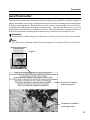
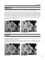
Auto Photo/Letter
This function automatically determines whether the image being scanned is text (binary image) or
photo (intermediate tone image), and scans the text areas in binary scanning mode and the photos
in halftone scanning mode. This function is used in order to automatically scan text in binary
scanning mode and photos in halftone scanning mode. This function allows you to scan an
original that contains both text and photos just once while automatically scanning each type of
area in the appropriate scanning mode without having to make special settings for each.
Limitation
❒ During double-sided scanning, this function is valid only for the front side of the original.
Note
❒ This function is valid only when the optional Image Processing Unit Type A is installed.
Original
Scanned in binary
scanning mode
Scanned in halftone
scanning mode
51
6. Appendices
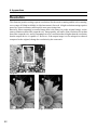
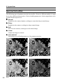
Resolution
This function permits setting separate resolutions for the main-scanning and the sub-scanning,
over a range of 100dpi to 800dpi (in 1dpi increments) for each. A high resolution setting requires
more free space in memory and requires more processing time.
Basically, when outputting a scanned image that is the same size as the original image, set the
same resolution as that of the output device. Image quality will suffer if the resolution is less than
that of the output device, and it is meaningless to set a resolution that is higher than the resolution
that the output device is capable of. However, if the output image is to be enlarged or reduced
compared to the original, change the resolution by the same ratio.
Original
Low resolution
52
High resolution
Functions
Brightness
The brightness can be adjusted to 255 levels. If a high value is set for the brightness, the image
will become brighter overall. If a low value is set, the image will become darker overall.
When scanning a dark original, set a high value for the brightness; when scanning a bright
original, set a low value for the brightness. For example, if a dark original is scanned normally,
any gradations in the darker portions will be lost and will appear to be solid black in the scanned
image. By increasing the brightness value in this case, the gradations in the darker portion will
also appear in the scanned image. Conversely, if the bright portions of an original become solid
white in the scanned image, lowering the brightness value will bring out the gradations in the
bright portion in the scanned image.
Low brightness
High brightness
Contrast
The contrast can be adjusted to 255 levels. If a high contrast value is set, the resulting image will
have high contrast and will be sharply defined. If a low contrast value is set, the resulting lowcontrast image will have a softer feel.
To produce a sharp image, increase the contrast value, to produce a soft image, decrease the
contrast value. For example, when scanning a photo of metal, glass, etc., set a high contrast value
in order to achieve a sharp feel.
Low contrast
High contrast
53
6. Appendices
Gamma Correction
The following types of gamma correction are possible. However, different models of output
devices have different characteristics. Select a suitable gamma curve for the original that is to be
scanned and the output device.
❖ Normal
Emphasizes the contrast slightly, resulting in a somewhat sharp scanned image.
❖ Sharp
Emphasizes the contrast, resulting in a sharp scanned image.
❖ Soft
Decreases the contrast, resulting in a soft scanned image.
❖ Linear
Outputs the image as scanned.
❖ User-defined
Downloads a user-defined gamma curve for gamma correction.
54
Normal
Sharp
Soft
Linear
Functions
Binary Filters
The following two filters can be used for binary scanning.
❖ Noise removal
This filter used to eliminate the unnecessary small dots that appear when scanning an original
that is the result of several generations of photocopying.
When filter is not used
When filter is used
❖ Smoothing
This filter is used to smooth out small bumps within an image.
When filter is not used
When filter is used
Note
❒ This function is valid only when the optional Image Processing Unit Type A is installed.
Parameter Download
This function allows a user to download user-created gamma curves and halftone patterns to the
scanner.
The details of how to download the data depends on the software being used.
55
6. Appendices
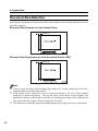
Document Size Detection
This function automatically detects the width of the original, and sends the information to the
personal computer.
Document Size Detection on the Contact Glass
5mm (0.2")
Document Size Detection in the Auto Document Feeder (ADF)
5mm (0.2")
Note
❒ If there is any coloring on the leading edge (5mm, 0.2”) of the original, the size of the
original might not be detected properly.
❒ If the sheets of the original are not set in position properly, the size of the original
might not be detected properly. Line up the edges of the sheets of the original, and
position the guides on both sides so that they are touching the edges of the original and
will ensure that the original feeds straight into the ADF.
❒ This function is valid only when the optional Image Processing Unit Type A is installed.
56
Functions
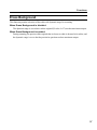
Erase Background
This function permits selection of the white side dynamic range for scanning.
When Erase Background is disabled
The dynamic range is set so that a white original (D value: 0.07) reaches maximum output.
When Erase Background is enabled
During scanning, the portion of the original that is closest to white is deemed to be white, and
the dynamic range is set so that the portion in question reaches maximum output.
57
6. Appendices
Index
A
F
ADF Cover ----------------------- 4, 29, 34
Area Extraction --------------------------- 49
Feed roller ----------------------------- 29, 35
Auto Document Feeder (ADF) --- 1, 3, 5,
17, 19, 21, 22, 23, 28, 29, 36, 37, 39
Auto Photo/Letter ------------------ 40, 51
Auxiliary Table ----------------------- 3, 21
B
Binary Filters ------------------------------ 55
Binary Scanning ---------------------- 45, 46
Gamma Correction ------------------------ 54
Gray Scale Scanning ---------------- 45, 48
H
Halftone Scanning ------------------- 45, 47
Home Position ------------------------ 20, 37
Brightness ---------------------------------- 53
I
C
Image Processing ------------------------- 40
Indicators --------------------------- 5, 27, 28
{Clear Modes} Button ---------------- 3, 26
Contact Glass ------------ 4, 17, 19, 20, 34
Initializing the Scanner ------------------ 16
ink ribbon ----------------------------------- 30
Contrast ------------------------------------- 53
Interface for Reverse Side Scanning ------- 4
ISIS -------------------------------------- 2, 25
D
Daisy Chain --------------------------- 10, 43
DIP Switch --------------------- 4, 10, 27, 43
Document in Place -------------------------- 5
Document Size Detection ----------- 40, 56
Document Table ----------------------- 3, 29
Drum ---------------------------------------- 34
Duplex Model -------------------------- 1, 42
Dynamic Threshold ------------------------ 40
E
Endorser ------- 1, 28, 30, 31, 32, 41, 42
Endorser Cover ------------------------- 3, 30
Erase Background ------------------------- 57
Error ------------------------------------------- 5
58
G
K
Knob ------------------------------ 29, 34, 36
M
Machine Busy ------------------------------- 5
Manual Scanning ------------------- 1, 5, 26
O
Output Table ------------------------ 3, 29, 30
Index
P
T
Parameter Download --------------------- 55
Platen --------------------------------------- 34
Terminator ------------------------ 10, 11, 43
Threshold ----------------------------------- 46
Power Cable -------------------------------- 13
Power Connector ----------------------- 4, 14
TWAIN --------------------------------- 2, 25
Power On ------------------------------------- 5
Power Switch ---------------------- 3, 13, 15
Preview ------------------------------------- 44
W
White Roller ------------------------------- 36
White Sheet ------------------------ 4, 34, 36
R
Red Lamp Unit ---------------------------- 40
Reset Switch ---------------------------- 4, 16
Resolution ---------------------------------- 52
Rotary Switch --------------------------- 4, 11
S
Scale ----------------------------------------- 20
SCAM --------------------------------- 10, 43
Scanner Indicators --------------------------- 3
Scanning Composition -------------------- 45
SCSI ----------------------------------------- 10
SCSI Board --------------------------------- 10
SCSI Cables ---------------- 10, 11, 27, 39
SCSI Connector ------------------------------ 4
SCSI ID --------------------------- 10, 11, 27
Section Area (Multi-area Settings) ------- 50
Simplex Model ----------------------------- 42
Slit Glass ------------------------------------ 34
{Start} Button --------------------------- 3, 26
Stopper ------------------------------ 3, 21, 22
59
6. Appendices
60