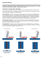
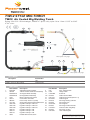
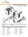
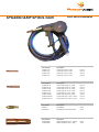
1
™
Razorweld
OPERATING MANUAL
™
KUMJRRW150
KUMJRRW195
3YEARS Warranty
(Power Source)
Please read and understand this instruction manual carefully
before the installation and operation of this equipment.
1
JASIC Technologies America Inc 2013
©
Thank you for your purchase of your RAZORWELD welding machine.
We are proud of our range of welding equipment that has a proven track record of innovation,
performance and reliability. Our product range represents the latest developments in Inverter
technology put together by our professional team of highly skilled engineers. The expertise gained
from our long involvement with inverter technology has proven to be invaluable towards the
evolution and future development of our equipment range. This experience gives us the inside
knowledge on what the arc characteristics, performance and interface between man and machine
should be. Within our team are specialist welders that have a proven history of welding knowledge
and expertise, giving vital input towards ensuring that our machines deliver control and
performance to the utmost professional level. We employ an expert team of professional sales,
marketing and technical personnel that provide us with market trends, market feedback and
customer comments and requirements. Secondly they provide a customer support service that is
second to none, thus ensuring our customers have confidence that they will be well satisfied both
now and in the future.
RAZORWELD welders are manufactured and compliant with - CAN/CSA E60974-1 &
ANSI/IEC 60974-1, guaranteeing you electrical safety and performance.
™
Razorweld
™
WARRANTY
• 3 Years from date of purchase.
•JASIC Technologies America Inc Ltd warranties all goods as specified by the manufacturer of those goods.
•This Warranty does not cover freight or goods that have been interfered with.
•All goods in question must be repaired by an authorised repair agent as appointed by this
company.
•Warranty does not cover abuse, mis-use, accident, theft, general wear and tear.
•New product will not be supplied unless JASIC Technologies America Inc has inspected
product returned for warranty and agree to replace product.
•Product will only be replaced if repair is not possible
™ • Please view full Warranty term and conditions supplied with machine or at www.razorweld.com
™
or at the back of this manual.
2
Razorweld
CONTENTSPAGE
Warranty2
Technical Data, Product Information
4-5
Safety - Cautions
6-8
Machine Layout Pictogram
9
Installation & Operation for MMA (stick) Welding
10
MMA (Stick) Welding Information
11-12
Installation & Operation for MIG Welding with Gas
13-14
Wire Feed Drive Roller Selection
15
Wire Installation Set up Guide
16
Installation & Operation for MIG Welding with No Gas
17-18
Installation Guide for Mig Torch Liner Installation
19
Mig Torch and Wire Feeder Set Up Guide for Aluminium Mig Wire
20-21
Installation & Operation for MIG Welding with Spool Gun
22-23
MIG (Metal Inert Gas) Welding
24-25
Basic MIG Welding Guide
26-29
TWC2 Torch Parts Breakdown
30-31
SP200II Spool Gun Torch Parts Breakdown
32-33
Mig Welding Shooting Guide
34-35
MMA Welding Trouble Shooting Guide
36
Spare Parts Identification
38-39
Warranty Terms and Conditions
40-42
MIG/MMA - 150 Amp DC Welding Machine
Lightweight & Portable
Welds: Steels, Stainless, Cast Iron, Bronze, Aluminium
3YEARS Warranty
(Power Source)
KUMJRRW150
• DUAL VOLTAGE (115~230V) - SINGLE PHASE
• LATEST IGBT + SMT TECHNOLOGY
• NEW ERGONOMIC PORTABLE DESIGN
• MIG/MAG WITH GAS & GASLESS FUNCTION
• OVER VOLTAGE PROTECTION
• THERMAL OVERLOAD PROTECTION
• SPOOL GUN READY
• STEPLESS VOLTAGE & WIRE SPEED CONTROL
• GEARED WIRE DRIVE MECHANISM
• INTERNAL WIRE FEEDER TAKES UP TO 8” Ø SPOOL
• MMA - HOT START – ANTI STICK
Technical Data
Power Supply / Phases (V-Ph)
Rated Input Power (KVA) ieff (Amps)
Imax (Amps)
Rated Output Welding Current Range No-Load Voltage (V) Duty Cycle @ 104ºF
Protection Class
Size (inches) Weight (pounds) Warranty
Compliant to
115V/230V - 1 ±15%
6 - 230V
17.5A 115V
15.5A 230V
30A 115V
25.5A 230V
150A/21.5V MIG
150A/26.0V MMA
30 ~150A
53V
35%@150Amps MIG-230V
35%@150Amps MMA-230V
IP21S
19.1” x 7.3” x 14.6”
28.4
3 years on power source
CAN/CSA E60974-1
ANSI/IEC 60974-1
OPTIONS
SPOOL GUN
Part No: SPG$"";;
The Razor 150 is a dual voltage inverter-based portable Multi-Function MIG welding machine. The MIG
function allows you to weld with both Gas Shielded and Gasless wires. The MMA welding capability
delivers easy electrode welding with high quality results, including cast Iron, stainless and low hydrogen.
The machine comes complete with a quality carry bag, Power Adaptor, MIG torch, ARC lead sets and Regulator.
A semi-industrial machine, it is lightweight and portable, Being both 115V and 230v single phase gives
great portability, Ideal for general engineers, maintenance workshop, rural workshop, panel beaters
and home workshops.
A superb looking machine whose good looks are backed up by ease of operation and standout
performance backed by a 3 year warranty*.
MACHINE PACKAGE:KUMJRRW150
4
RAZOR 150 MIG-MMA, Earth Lead & Arc Lead 0.62” x 13ft, TWC2 MIG Torch 13ft, Power adaptor
Argon Regulator, Carry Bag.
MIG/MMA - 195 Amp DC Welding Machine
Lightweight & Portable
Welds: Steels, Stainless, Cast Iron, Bronze, Aluminium
3YEARS Warranty
(Power Source)
KUMJRRW195
• DUAL VOLTAGE (115~230V) - SINGLE PHASE
• LATEST IGBT + SMT TECHNOLOGY
• NEW ERGONOMIC PORTABLE DESIGN
• MIG/MAG WITH GAS & GASLESS FUNCTION
• OVER VOLTAGE PROTECTION
• THERMAL OVERLOAD PROTECTION
• SPOOL GUN READY
• STEPLESS VOLTAGE & WIRE SPEED CONTROL
• GEARED WIRE DRIVE MECHANISM
• INTERNAL WIRE FEEDER TAKES UP TO 8” Ø SPOOL
• MMA - HOT START – ANTI STICK
Technical Data
Power Supply / Phases (V-Ph)
Rated Input Power (KVA) ieff (Amps)
Imax (Amps)
Rated Output Welding Current Range No-Load Voltage (V) Duty Cycle @ 104ºF
Protection Class
Size (inches) Weight (pounds) Warranty
Compliant to
115V/230V - 1 ±15%
6 - 230V
22.5A 115V
21.5A 230V
38A 115V
36A 230V
200A/24.0V MIG
200A/28.0V MMA
30 ~200A
53V
35%@200Amps MIG-230V
35%@200Amps MMA-230V
IP21S
19.1” x 7.3” x 14.6”
28.4
3 years on power source
CAN/CSA E60974-1
ANSI/IEC 60974-1
OPTIONS
SPOOL GUN
Part No: SPG$"";;
The Razor 195 is a compact dual voltage inverter-based portable Multi-Function MIG welding machine.
The MIG function allows you to weld with both Gas Shielded and Gasless wires. The MMA welding
capability delivers easy electrode welding with high quality results, including cast Iron, stainless and low
hydrogen. The machine comes complete with a quality carry bag, Power Adaptor, MIG torch, ARC lead sets
and Regulator. A semi-industrial machine, it is lightweight and portable, Being both 115V and 230v
single phase gives great portability, Ideal for general engineers, maintenance workshop, rural workshop,
panel beaters and home workshops.
A superb looking machine whose good looks are backed up by ease of operation and standout performance backed by a 3 year warranty*.
MACHINE PACKAGE:KUMJRRW195
RAZOR 150 MIG-MMA, Earth Lead & Arc Lead 0.62” x 13ft, TWC2 MIG Torch 13ft, Power adaptor
Argon Regulator, Carry Bag.
5
SAFETY
Welding and cutting equipment can be dangerous to both the operator and people in or near the
surrounding working area, if the equipment is not correctly operated. Equipment must only be
used under the strict and comprehensive observance of all relevant safety regulations.
Read and understand this instruction manual carefully before the installation and operation of this
equipment.
Machine Operating Safety
•Do not switch the function modes while the machine is operating. Switching of the function modes during
welding can damage the machine. Damage caused in this manner will not be covered under warranty.
•Disconnect the electrode-holder cable from the machine before switching on the machine, to avoid arcing
should the electrode be in contact with the work piece.
•Operators should be trained and or qualified.
Electric shock: It can kill. Touching live electrical parts can cause fatal shocks or severe
burns. The electrode and work circuit is electrically live whenever the output is on. The input
power circuit and internal machine circuits are also live when power is on. In Mig/Mag welding,
the wire, drive rollers, wire feed housing, and all metal parts touching the welding wire are
electrically live. Incorrectly installed or improperly grounded equipment is dangerous.
•Connect the primary input cable according to Australian and New Zealand standards and regulations.
•Avoid all contact with live electrical parts of the welding circuit, electrodes and wires with bare hands.
The operator must wear dry welding gloves while he/she performs the welding task.
•The operator should keep the work piece insulated from himself/herself.
• Keep cords dry, free of oil and grease, and protected from hot metal and sparks.
• Frequently inspect input power cable for wear and tear, replace the cable immediately if damaged,
bare wiring is dangerous and can kill.
•Do not use damaged, under sized, or badly joined cables.
•Do not drape cables over your body.
Fumes and gases are dangerous. Smoke and gas generated whilst welding or cutting can
be harmful to people’s health. Welding produces fumes and gases. Breathing these fumes and
gases can be hazardous to your health. •Do
not breathe the smoke and gas generated whilst welding or cutting, keep your head out of the fumes
•Keep the working area well ventilated, use fume extraction or ventilation to remove welding fumes and
gases.
•In confined or heavy fume environments always wear an approved air-supplied respirator.
Welding fumes and gases can displace air and lower the oxygen level causing injury or death. Be sure the
breathing air is safe.
•Do not weld in locations near de-greasing, cleaning, or spraying operations. The heat and rays of the arc
can react with vapours to form highly toxic and irritating gases.
•Materials such as galvanized, lead, or cadmium plated steel, containing elements that can give off toxic
fumes when welded. Do not weld these materials unless the area is very well ventilated, and or wearing
an air supplied respirator.
Arc rays: harmful to people’s eyes and skin. Arc rays from the welding process produce
intense visible and invisible ultraviolet and infrared rays that can burn eyes and skin.
•Always
wear a welding helmet with correct shade of filter lens and suitable protective clothing including
welding gloves whilst the welding operation is performed.
•Measures should be taken to protect people in or near the surrounding working area. Use protective
screens or barriers to protect others from flash,glare and sparks; warn others not to watch the arc.
6
Fire hazard. Welding on closed containers, such as tanks,drums, or pipes, can cause them
to explode. Flying sparks from the welding arc, hot work piece, and hot equipment can cause
fires and burns. Accidental contact of electrode to metal objects can cause sparks, explosion,
overheating, or fire. Check and be sure the area is safe before doing any welding.
•The
welding sparks may cause fire, therefore remove any flammable materials away from the working
area, at least 12 yards from the welding arc. Cover flammable materials and containers with approved
cover if unable to be moved from the welding area.
•Do not weld on closed containers such as tanks, drums, or pipes, unless they are properly prepared
according to the required Safety Standards to insure that flammable or toxic vapors and substances are
totally removed, these can cause an explosion even though the vessel has been “cleaned”.
Vent hollow castings or containers before heating, cutting or welding. They may explode.
•Do not weld where the atmosphere may contain flammable dust, gas, or liquid vapours (such as petrol)
•Have a fire extinguisher nearby and know how to use it. Be alert that welding sparks and hot materials
from welding can easily go through small cracks and openings to adjacent areas. Be aware that welding
on a ceiling, floor, bulkhead, or partition can cause fire on the hidden side.
Gas Cylinders. Shielding gas cylinders contain gas under high pressure. If damaged, a cylinder can explode. Because gas cylinders are normally part of the welding process, be sure to
treat them carefully. CYLINDERS can explode if damaged.
•Protect
gas cylinders from excessive heat, mechanical shocks, physical damage, slag, open flames,
sparks, and arcs.
•Insure cylinders are held secure and upright to prevent tipping or falling over.
•Never allow the welding electrode or earth clamp to touch the gas cylinder, do not drape welding cables
over the cylinder.
•Never weld on a pressurised gas cylinder, it will explode and kill you.
•Open the cylinder valve slowly and turn your face away from the cylinder outlet valve and gas regulator.
Gas
build up. The build up of gas can causes a toxic environment, deplete the oxygen content
in the air resulting in death or injury. Many gases use in welding are invisible and odourless.
•Shut off shielding gas supply when not in use.
•Always ventilate confined spaces or use approved air-supplied respirator.
Electronic magnetic fields. MAGNETIC FIELDS can affect Implanted Medical Devices.
•Wearers of Pacemakers and other Implanted Medical Devices should keep away.
•Implanted Medical Device wearers should consult their doctor and the device manufacturer before going
near any electric welding, cutting or heating operation.
Noise can damage hearing. Noise from some processes or equipment can damage hearing.
Wear approved ear protection if noise level is high.
Hot parts. Items being welded generate and hold high heat and can cause severe burns.
Do not touch hot parts with bare hands. Allow a cooling period before working on the welding
gun. Use insulated welding gloves and clothing to handle hot parts and prevent burns.
7
CAUTION
1. Working Environment.
1.1 The environment in which this welding equipment is installed must be free of grinding dust, corrosive
chemicals, flammable gas or materials etc, and at no more than maximum of 80% humidity.
1.2 When using the machine outdoors protect the machine from direct sun light, rain water and snow etc;
the temperature of working environment should be maintained within -10°C to +40°C..
1.3 1.4 Ensure the working environment is well ventilated.
2. Safety Tips.
2.1 Ventilation
This equipment is small-sized, compact in structure, and of excellent performance in amperage output.
The fan is used to dissipate heat generated by this equipment during the welding operation.
Important: Maintain good ventilation of the louvers of this equipment. The minimum distance between
this equipment and any other objects in or near the working area should be 1ft.Good ventilation is
of critical importance for the normal performance and service life of this equipment.
2.2
Thermal Overload protection.
2.3
Over-Voltage Supply
Should the machine be used to an excessive level, or in high temperature environment, poorly
ventilated area or if the fan malfunctions the Thermal Overload Switch will be activated and the
machine will cease to operate. Under this circumstance, leave the machine switched on to keep the
built-in fan working to bring down the temperature inside the equipment. The machine will be ready for
use again when the internal temperature reaches safe level.
Regarding the power supply voltage range of the machine, please refer to “Main parameter” table.
This equipment is of automatic voltage compensation, which enables the maintaining of the voltage
range within the given range. In case that the voltage of input power supply amperage exceeds the
stipulated value, it is possible to cause damage to the components of this equipment. Please ensure
your primary power supply is correct.
2.4 Do not come into contact with the output terminals while the machine is in operation. An electric shock
may possibly occur.
MAINTENANCE
Exposure to extremely dusty, damp, or corrosive air is damaging to the welding machine. In order to prevent any possible failure or fault of this welding equipment, clean the dust at regular intervals with clean and
dry compressed air of required pressure.
Please note that: lack of maintenance can result in the cancellation of the guarantee; the guarantee of
this welding equipment will be void if the machine has been modified, attempt to take apart the machine or
open the factory-made sealing of the machine without the consent of an authorized representative of the
manufacturer.
TROUBLE SHOOTING
Caution: Only qualified technicians are authorized to undertake the repair of this welding equipment.
For your safety and to avoid Electrical Shock, please observe all safety notes and precautions
detailed in this manual.
Note:
Minimum Motor Generator Power Suggested:- 6.5KVA for M:8 150 - 7KVA for MIG195
8
1
FRONT PANEL LAYOUT
1. Mains Power LED
2. Thermal Overload LED
3. Wire Feed Adjustment Knob (MIG/MAG)
4. Voltage Adjustment Knob (MIG/MAG)
5. MIG/MMA Selector Switch
6. Amperage Adjustment Knob (MMA)
7. “-” Output terminal
8. Euro Mig Torch Connector (MIG/MAG)
9. “+” Output terminal
10. SpoolGun Power Supply Connection
2
3
4
5
6
7
8
10
9
BACK PANEL LAYOUT
11. Power switch
12. Gas Inlet
13. Fan
14. Input power cable
15. Data Plate
11
14
12
15
13
16
17
18
INTERNAL PANEL LAYOUT
16. Burn back control
17. Spoolgun/Standard selector switch
18. Inch wire feed button
19. Spool holder assembly
20. Wire feed assembly
19
20
9
Installation set up for MMA (Stick) Welding with XA-MIG200 RAZORWELD
(1) Turn the power source on and select the MMA function with the MMA/M:8 selector switch.
(2) Connection of Output Cables
Two sockets are available on this welding machine. For MMA welding the electrode holder is shown
be connected to the negative socket, while the earth lead (work piece) is connected to the positive
socket, this is known as DC- polarity. However various electrodes require a different polarity for
optimum results and careful attention should be paid to the polarity, refer to the electrode
manufacturers information for the correct polarity.
DC+ Electrode connected to
output socket.
DC- Electrode connected to
output socket.
(3) Set the welding current relevant to the electrode type and size being used as recommended by the
electrode manufacturer.
(1) Set MMA/M:8 selector
switch to MMA
(2) Connect earth
lead to
(2) Connect the electrode
lead to
10
3) Set the welding current using
the amperage control dial
4) Place the electrode into the electrode
holder and clamp tight.
5) Strike the electrode against the work
piece to create and arc and hold the electrode steady to maintain the arc
6) Hold the electrode slightly above the
work maintaining the arc while travelling
at an even speed.
7) To finish the weld, break the arc by
quickly snapping the electrode away from
the work piece.
8) Wait for the weld to cool and carefully
chip away the slag to reveal the weld
metal below.
MMA (Manual Metal Arc) Welding
One of the most common types of arc welding is manual metal arc welding (MMA) or stick welding. An electric current is used to strike an arc between the base material and a consumable electrode rod or ‘stick’. The electrode rod
is made of a material that is compatible with the base material being welded and is covered with a flux that gives off
gaseous vapours that serve as a shielding gas and providing a layer of slag, both of which protect the weld area from
atmospheric contamination. The electrode core itself acts as filler material the residue from the flux that forms a slag
covering over the weld metal must be chipped away after welding.
Core wire
+
Flux coating
Gas shield from flux melt
Power Source
Arc with core wire melt
Flux residue forms slag cover
Weld metal
▬
• The arc is initiated by momentarily touching the electrode to the base metal.
Core wire
Flux coating
Base metal
• The heat of the arc melts the surface of the base metal to form a molten pool
at the end of the electrode.
• The melted electrode metal is transferred across the arc into the molten pool
and becomes the deposited weld metal.
• The deposit is covered and protected by a slag which comes from the
electrode coating.
• The arc and the immediate area are enveloped by an atmosphere of
protective gas
Protective gas
Arc
Manual metal arc ( stick) electrodes have a solid metal wire core and a flux
coating. These electrodes are identified by the wire diameter and by
a series of letters and numbers. The letters and numbers identify the metal
alloy and the intended use of the electrode.
The Metal Wire Core works as conductor of the current that maintains the arc.
The core wire melts and is deposited into the welding pool.
Slag
Weld pool
The covering on a shielded metal arc welding electrode is called Flux.
The flux on the electrode performs many different functions.
These include:
● producing a protective gas around the weld area
● providing fluxing elements and deoxidizers
● creating a protective slag coating over the weld as it cools
● establishing arc characteristics
● adding alloying elements.
Covered electrodes serve many purposes in addition to adding filler metal to
the molten pool. These additional functions are provided mainly by the covering on the electrode.
11
MMA (Stick) Welding Fundamentals
Electrode Selection
As a general rule, the selection of an electrode is straight forward,in that it is only a matter of selecting an
electrode of similar composition to the parent metal. However, for some metals there is a choice of several
electrodes, each of which has particular properties to suit specific classes of work. It is recommend to
consult your welding supplier for the correct selection of electrode.
Electrode Size
Average Thickness
of Material
Maximum Recommended
Electrode Diameter
0.03 - 0.07 inches
0.07 - 0.19 inches
0.19 - 0.31 inches
0.31 - > inches
0.09 inches
0.12 inches
0.15 inches
0.19 inches
The size of the electrode generally depends on the
thickness of the section being welded, and the thicker
the section the larger the electrode required. The table
gives the maximum size of electrodes that maybe used
for various thicknesses of section based on using a
general purpose type 6013 electrode.
Welding Current (Amperage)
Correct current selection for a particular job is an
important factor in arc welding. With the current set too
low, difficulty is experienced in striking and maintaining
a stable arc. The electrode tends to stick to the work,
0.09 inches
60 - 100
penetration is poor and beads with a distinct rounded
0.12 inches
100 - 130
profile will be deposited. Too high current is
0.15 inches
130 - 165
accompanied by overheating of the electrode resulting
0.19 inches
165 - 260
undercut and burning through of the base metal and
producing excessive spatter. Normal current for a particular job may be considered as the maximum, which
can be used without burning through the work, over-heating the electrode or producing a rough spattered
surface.The table shows current ranges generally recommended for a general purpose type 6013
electrode.
Electrode Size
ø mm
Current Range
(Amps)
Arc Length
To strike the arc, the electrode should be gently scraped on the work until the arc is established. There is a
simple rule for the proper arc length; it should be the shortest arc that gives a good surface to the weld. An
arc too long reduces penetration, produces spatter and gives a rough surface finish to the weld.
An excessively short arc will cause sticking of the electrode and result in poor quality welds. General rule of
thumb for down hand welding is to have an arc length no greater than the diameter of the core wire.
Electrode Angle
The angle that the electrode makes with the work is important to ensure a smooth, even transfer of metal.
When welding in down hand, fillet, horizontal or overhead the angle of the electrode is generally between 5
and 15 degrees towards the direction of travel. When vertical up welding the angle of the electrode should
be between 80 and 90 degrees to the work piece.
Travel Speed
The electrode should be moved along in the direction of the joint being welded at a speed that will give the
size of run required. At the same time, the electrode is fed downwards to keep the correct arc length at all
times. Excessive travel speeds lead to poor fusion, lack of penetration etc, while too slow a rate of travel
will frequently lead to arc instability,slag inclusions and poor mechanical properties.
Material and Joint Preparation
The material to be welded should be clean and free of any moisture, paint, oil, grease, mill scale, rust or
any other material that will hinder the arc and contaminate the weld material. Joint preparation will depend
on the method used include sawing, punching, shearing, machining, flame cutting and others. In all cases
edges should be clean and free of any contaminates. The type of joint will be determined by the chosen
application.
12
Installation set up for MIG with Gas for RAZOR 150/195 MIG
(1) Select the MIG function with the MMA/MIG selector switch.
(2) Select Standard using the Standard/Spool Gun selector switch.
(3) Plug the welding torch into the Euro Mig torch connection socket on the front panel, and tighten it.
IMPORTANT : When connecting the torch be sure to tighten the connection. A loose connection can
result in the connector arcing and damaging the machine and gun connector.
This damage is not covered under warranty.
(4) Insert the earth cable plug into the negative socket on the front of the machine and tighten it.
(5) Connect Gas Line to Gas Regulator and connect the gas regulator to the Gas Cylinder.
(6) Connect the weld power cable plug inside the wire feeder to the output socket GAS, and tighten it.
(7) Place the Wire Spool onto the Spool Holder - Note: the spool retaining nut is Left Hand thread.
Snip the wire from the spool being sure to hold the wire to prevent rapid uncoiling. Feed the wire into
thewire feeder inlet guide tube through to the drive roller.
(8) Carefully feed the wire over the drive roller into the outlet guide tube, feed through about 5.9" into
the torch receptacle. Check that the drive roller being used complies with the wire diameter, replace the
roller if necessary.
(5) Connect the gas line to the regulator and
connect to the gas cylinder
(1) Set MMA/MIG selector
switch to Mig
(2) Set Standard/Spoolgun
selector switch inside door
to Standard
(3) Connect MIG torch
(4) Connect earth lead to
IMPORTANT : When connecting the torch
be sure to tighten the connection.
(6) Connect weld power lead to
(7) Place wire onto spool holder - (spool retaining
nut is left hand thread ) Feed the wire through the
inlet guide tube on to the drive roller.
(8) Feed wire over the drive roller into
the outlet guide tube, Push the wire
through approx 5.9 Inches.
Caution:
Disconnect the Electrode Holder cable from the machine before using MIG function. If cable is not disconnected welding
voltage is present and can cause arcing or flash.
13
Continued set up for MIG with Gas for RAZOR 150/195 MIG
(9) Align the wire into the groove of the drive roller and close down the top roller making sure the wire is in
the groove of the bottom drive roller, lock the pressure arm into place.
(10) Apply a medium amount of pressure to the drive roller.
(11) Remove the gas nozzle and contact tip from the torch neck,
(12) Press and hold the inch button to feed the wire through to the torch neck, release the inch button when
the wire exits the torch neck.
(13) Fit the correct sized contact tip and feed the wire through it, screw the contact tip into the tip holder of
the torch head and nip it up tightly.
(14) Fit the gas nozzle to the torch head.
(15) Carefully open the gas cylinder valve and set the flow rate to between 15-25 CFH.
(16) Set the welding parameters using the wire feed and voltage control knobs.
(17) Using the Burn Back control set the amount of wire to ‘burn back’ after you release the torch
trigger. This prevents the wire becoming stuck in the weld pool when finishing the weld.
14
(9) Close down the top roller bracket and clip
the pressure arm into place.
(10) Apply a medium amount of
pressure to the drive roller
(11) Remove the gas nozzle and contact tip
from the front end of the mig torch.
(12) Press and hold the inch wire button to
feed the wire down the torch cable through
to the torch head.
(13) Fit the correct size contact tip over
the wire and fasten tightly into the tip
holder.
(14) Fit the gas nozzle to the torch head.
(15) Carefully open the valve of the gas
cylinder, set the flow to 25CFH
(16) Set welding parameters using the
voltage and wire feed controls.
(17) Adjust the burn back control to prevent
the wire sticking in the weld pool.
Wire Feed Roller Selection
The importance of smooth consistent wire feeding during MIG welding cannot be emphasized enough.
Simply put the smoother the wire feed then the better the welding will be.
Feed rollers or drive rollers are used to feed the wire mechanically along the length of the welding gun.
Feed rollers are designed to be used for certain types of welding wire and they have different types of
grooves machined in them to accommodate the different types of wire. The wire is held in the groove by
the top roller of the wire drive unit and is referred to as the pressure roller, pressure is applied by a tension
arm that can be adjusted to increase or decrease the pressure as required. The type of wire will determine
how much pressure can be applied and what type of drive roller is best suited to obtain optimum wire feed.
Solid Hard Wire - like Steel, Stainless Steel require a drive roller with a V shape groove for optimum grip
and drive capability. Solid wires can have more tension applied to the wire from the top pressure roller that
holds the wire in the groove and the V shape groove is more suited for this. Solid wires are more forgiving
to feed due to their higher cross sectional column strength, they are stiffer and don’t bend so easy.
Soft Wire - like Aluminium requires a U shape groove. Aluminium wire has a lot less column strength, can
bend easily and is therefore more difficult to feed. Soft wires can easily buckle at the wire feeder where the
wire is fed into inlet guide tube of the torch. The U-shaped roller offers more surface area grip and traction
to help feed the softer wire. Softer wires also require less tension from the top pressure roller to avoid
deforming the shape of the wire, too much tension will push the wire out of shape and cause it to catch in
the contact tip.
Flux Core / Gasless Wire - these wires are made up of a thin metal sheath that has fluxing and metal
compounds layered onto it and then rolled into a cylinder to form the finished wire. The wire cannot take
too much pressure from the top roller as it can be crushed and deformed if too much pressure is applied.
A knurled drive roller has been developed and it has small serrations in the groove, the serrations grip the
wire and assist to drive it without too much pressure from the top roller. The down side to the knurled wire
feed roller on flux cored wire is it will slowly over time bit by bit eat away at the surface of the welding wire,
and these small pieces will eventually go down into the liner. This will cause clogging in the liner and added
friction that will lead to welding wire feed problems. A U groove wire can also be used for flux core wire
without the wire particles coming of the wire surface. However it is considered that the knurled roller will
give a more positive feed of flux core wire without any deformation of the wire shape.
Top Pressure Roller
Top Pressure Roller
V Groove
U Groove
Wire
Top Pressure Roller
Knurled Groove
Wire
Wire
V Groove Drive Roller - Steel Wire
Drive Rollers
OSD
V
Part Number MIG150
MIG195
0.6-0.8V30/10
0.6-0.8V30/22
0.8-1.0V30/10
0.8-1.0V30/22
0.9-1.2V30/10
0.9-1.2V30/22
1.0-1.2V30/10
1.0-1.2V30/22
Description
Drive Roll V Groove 0.6-0.8mm / 0.023” - 0.030”
Drive Roll V Groove 0.8-1.0mm / 0.030” - 0.040”
Drive Roll V Groove 0.9-1.2mm / 0.035” - 0.045”
Drive Roll V Groove 1.0-1.2mm / 0.040” - 0.045”
U Groove Drive Roller - Soft Wire
Out Side Diameter
ISD
In Side Diameter
U
Part Number MIG150
MIG195
0.8-1.0U30/10
0.8-1.0U30/22
0.9-1.0U30/10
0.9-1.0U30/22
0.9-1.2U30/10
0.9-1.2U30/22
1.0-1.2U30/10
1.0-1.2U30/22
Description
Drive Roll U Groove 1.0-1.2mm / 0.040” - 0.045
Drive Roll U Groove 0.9-1.0mm / 0.035” - 0.040”
Drive Roll U Groove 0.9-1.2mm / 0.035” - 0.045”
Drive Roll U Groove 1.0-1.2mm / 0.040” - 0.045”
Knurled Drive Roller - Flux Core Wire
F
Part Number MIG150
MIG195
0.6-0.8F30/10
0.6-0.8F30/22
0.8-0.9F30/10
0.8-0.9F30/22
0.9-1.2F30/10
0.9-1.2F30/22
Description
Drive Roll Knurled 0.6-0.9mm / 0.023” - 0.035”
Drive Roll Knurled 0.8-0.9mm / 0.030” - 0.035”
Drive Roll Knurled 0.9-1.2mm / 0.035” - 0.045”
15
Wire Installation and Set Up Guide
Again the importance of smooth consistent wire feeding during MIG welding cannot be emphasized enough.
The correct installation of the wire spool and the wire into the wire feed unit is critical to achieving an even
and consistent wire feed. A high percentage of faults with mig welders emanate from poor set up of the
wire into the wire feeder. The guide below will assist in the correct setup of your wire feeder.
(1) Remove the spool retaining nut.
(4) Snip the wire carefully, be sure to hold the
wire to prevent the spool uncoiling. Carefully
feed the wire into the inlet guide tube of the
wire feed unit.
(7) Check that the wire passes through
the centre of the outlet guide tube without
touching the sides. Loosen the locking
screw and then loosen the outlet guide
tube retaining nut too make adjustment if
required. Carefully retighten the locking nut
and screw to hold the new position.
16
(2) Note the tension spring adjuster
and spool locating pin.
(5) Feed the wire through the drive roller and
into the outlet guide tube of the wire feeder.
(8) A simple check for the correct drive tension
is to bend the end of the wire over hold it about
100mm from your hand and let it run into your
hand, it should coil round in your hand without
stopping and slipping at the drive rollers,
increase the tension if it slips.
(3) Fit the wire spool onto the spool holder
fitting the locating pin into the location hole
on the spool. Replace the spool retaining
nut tightly
(6) Lock down the top pressure roller and
apply a medium amount of pressure using the tension adjustment knob
(8) The weight and speed of the wire spool
turning creates an inertia that can cause the
spool to run on and the wire loop over the
side of the spool and tangle. if this happens
increase the pressure on the tension spring
inside the spool holder assembly using the
tension adjustment screw.
Installation set up for MIG with Gasless wire for RAZOR 150/195 MIG
(1) Switch on the machine, select the MIG function with the MMA/MIG selector switch.
(2) Select Standard using the Standard/Spool Gun selector switch.
(3) Plug the welding torch into the Euro Mig torch connection socket on the front panel, and tighten it.
IMPORTANT : When connecting the torch be sure to tighten the connection. A loose connection can
result in the connector arcing and damaging the machine and gun connector.
This damage is not covered under warranty.
(4) Insert the earth cable plug into the Positive socket on the front of the machine and tighten it.
(5) Connect the weld power cable plug inside the wire feeder to the output socket NO GAS, and tighten it.
(6) Fit the correct size Knurled drive roller for Gas Less Flux Core wire.
(7) Place the Wire Spool onto the Spool Holder - Note: the spool retaining nut is Left Hand thread.
Snip the wire from the spool being sure to hold the wire to prevent rapid uncoiling. Feed the wire into
thewire feeder inlet guide tube through to the drive roller.
Set MMA/Mig selector
switch to Mig
Set Standard/Spoolgun
selector switch inside the
door to Standard
(3) Connect MIG torch
IMPORTANT : When connecting the torch
be sure to tighten the connection.
Connect earth lead to
(5) Connect weld power lead to
NO GAS
(6) Fit the correct sized Knurled Drive
roller for Gas Less Flux Cored wire
(7) Place wire onto spool holder - (spool
retaining nut is left hand thread ) Feed the wire
through the inlet guide tube on to the drive roller.
Caution:
Disconnect the Electrode Holder cable from the machine before using MIG function. If cable is not disconnected welding
voltage is present and can cause arcing or flash.
17
Continued set up for MIG with Gasless wire for RAZOR 150/195 MIG
(8) Carefully feed the wire over the drive roller into the outlet guide tube, feed through about 5.9" into
the torch receptacle. Check that the correct drive roller is being used.
(9) Align the wire into the groove of the drive roller and close down the top roller making sure the wire is in
the groove of the bottom drive roller, lock the pressure arm into place.
(10) Apply a light amount of pressure to the drive roller. Too much pressure will crush the cored wire.
(11) Remove the gas nozzle and contact tip from the torch neck,
(12) Press and hold the inch button to feed the wire through to the torch neck, release the inch button when
the wire exits the torch neck.
(13) Fit the correct sized contact tip and feed the wire through it, screw the contact tip into the tip holder of
the torch head and nip it up tightly.
(14) Fit the gas nozzle to the torch head.
(16) Set the welding parameters using the wire feed and voltage control knobs.
(17) Using the Burn Back control set the amount of wire to ‘burn back’ after you release the torch
trigger. This prevents the wire becoming stuck in the weld pool when finishing the weld.
18
(8) Feed wire over the drive roller into
the outlet guide tube, Push the wire
through approx 5.9". Use a Knurled
Drive Roller of the correct size
(9) Close down the top roller bracket and clip
the pressure arm into place.
(10) Apply a medium amount of
pressure to the drive roller
(11) Remove the gas nozzle and contact
tip from the front end of the mig torch.
(12) Press and hold the inch wire button
to feed the wire down the torch cable
through to the torch head.
(13) Fit the correct size contact tip over
the wire and fasten tightly into the tip
holder.
(14) Fit the gas nozzle to the torch head.
(16) Set welding parameters using the
voltage and wire feed controls.
(17) Adjust the burn back control to
prevent the wire sticking in the
weld pool.
Mig Torch Liner Installation
(1)
(2) (3) (4) (5) (6) (7) (8) (9) Lay the torch out straight on the ground and remove the front end parts
Remove the liner retaining nut.
Carefully pull the liner out of the torch cable assembly
Select the correct new liner and carefully unravel avoiding putting any kinks in the liner, if you kink the
liner it will make it no good and will require replacement.
Carefully and slowly feed the liner in short forward movements down the cable assembly all the way
through and out the torch neck end. Avoid kinking the liner, kinking liner it will make it no good and
require replacement.
Fit the liner retaining nut and screw down only 1/2 way
Leaving the torch straight snip the liner approximately 0.118" past the end of the torch neck
Place the tip holder over the end of the liner and screw into the torch neck nipping it up tight.
Screw down the liner nut the remaining 1/2 and nip it up tight. This method compresses the liner
inside the torch cable assembly preventing it moving during use and ensures good wire feed.
(1) Remove MIG torch front end parts
(2) Remove the liner retaining nut
(3) Carefully pull out and completely
remove the liner
(4) Carefully unravel the new liner
(5) Carefully feed in the new liner down
the torch lead all the way to exit the torch
neck.
(6) Fit the liner retaining nut and screw
only 1/2 way down
(7) Snip the liner off 3mm past the end of the
torch neck.
(8) Replace the front end parts
(9) Fully screw down the liner retaining
nut and nip it up tight.
19
Torch & Wire Feed Set Up for Aluminium Wire
(1)
(2) (3) (4) (5) (5) (8) (9) 20
Lay the torch out straight on the ground and remove the front end parts
Remove the liner retaining nut.
Carefully pull the liner out of the torch cable assembly
Select a PA or liner, carefully and slowly feed the liner in short forward movements down the cable
assembly all the way through and out the torch neck end. Avoid kinking the liner, kinking the liner will
ruin it and require replacement.
Leave the liner extending out the end of the torch neck end by 0.188".
Fit the liner retaining nuttogether with the liner o-ring.
Push the liner firmly into the torch lead and tighten the liner retaining nut.
Install a U groove drive roller of the correct size to match the wire diameter being used.
(1) Remove MIG torch front end parts
(2) Remove the liner retaining nut
(4) Carefully unravel the new liner
(5) Carefully feed in the new liner in short
forward movements down the torch lead
all the way to exit the torch neck.
Be careful not to kink the liner
(6) Replace the front end parts
(7) Fit the liner collet, liner O-ring and
liner retaining nut.
(8) Push the liner firmly into the torch lead
and tighten the liner retaining nut
(9) Cut the liner flush with the end of
liner retaining nut using a sharp box
cutter knife.
(3) Carefully pull out and completely
remove the liner
Continued Torch & Wire Feed Set Up for Aluminium Wire
(10) Loosen off the inlet guide tube retaining screw
(11) Remove the inlet guide tube from the front end machine euro connector using long nose pliers.
(12) Carefully feed the extended PA liner section into the inlet guide tube hole of the machine euro
connector
(13) Feed the extended PA liner all the way up and over the drive roller
(14) Tighten the torch euro connection to the machine euro connector
(15) Cut the extended liner with a sharp Stanley knife just in front of the drive roller
(16) Fit an Aluminium contact tip of the correct size to match the diameter of the wire being used
(17) Fit the remaining front end parts to the torch neck ready for welding
(10)Connect the torch to the machine
tighten and secure the torch euro
connector to the machine
euro connection.
(12) Press and hold the inch wire
button to feed the wire down the torch
cable through to the torch head.
(11) Install a U groove drive roller of the
correct size for the diameter wire being
used.
(16) Fit an Aluminium contact tip of the
correct size to match the wire diameter
being used
(7) Place aluminium wire onto spool holder.
Feed the wire through the inlet guide tube
on to the drive roller.
(17) Fit the remaining front end parts to
the torch neck ready for welding.
21
Installation set up of the Spool Gun for RAZOR 150/195 MIG
(1) Switch on the machine, select the MIG function with the MMA/Mig selector switch.
(2) Select Spool Gun using the Standard/Spool Gun selector switch.
(3) Connect the Spool Gun to the Euro Mig torch connection socket on the front panel, and tighten it.
Connect the Spool Gun control cable to the receptacle and tighten it.
IMPORTANT : When connecting the torch be sure to tighten the connection. A loose connection can
result in the connector arcing and damaging the machine and gun connector.
This damage is not covered under warranty.
(4) Insert the earth cable plug into the Negative socket on the front of the machine and tighten it.
(5) Connect Gas Line to Gas Regulator and connect the gas regulator to the Gas Cylinder.
(6) Take the Spool Gun and remove the spool cover.
(7) Place the Wire Spool onto the Spool Holder - Hold and snip the wire from the spool being sure to
hold the wire to prevent rapid uncoiling.
(8) Connect the gas line to the regulator and connect to the gas cylinder
(3) Set MMA/Mig/Spool Gun
selector
switch to Spool Gun
(5) If required select downslope time
for crater fill
(4) Set Torch operation
2T/4T
(6) Select Post gas flow time.
(7) Select Inductance control.
( 2) Connect earth lead to
(1) Connect Spool Gun control
cable and gun cable connector
IMPORTANT : When connecting the
torch
be sure to tighten the connection.
(5) Connect weld power lead to
output terminal
Caution:
(6) Remove the spool cover by unscrewing the retaining nut and lifting off the
cover
(7) Place a spool of wire onto the Spool
holder.
Disconnect the Electrode Holder cable from the machine before using MIG function. If cable is not disconnected welding
voltage is present and can cause arcing or flash.
22
Continued set up of the Spool Gun with RAZOR MIG150/195
(9) Connect weld power lead to GAS
(10) Take the Spool Gun and push the Cover Release Button to unlock the wire feed / spool cover.
(11) Place the Wire Spool onto the Spool Holder - Note: the spool retaining nut is Left Hand thread.
Hold and snip the wire from the spool being sure to hold the wire to prevent rapid uncoiling.
(12) Carefully feed the wire over the drive roller into the outlet guide tube, feed through into the torch neck. Check that the drive roller being used complies with the wire diameter, replace the roller if necessary.
(13) Align the wire into the groove of the drive roller and release the tension arm making sure the wire is
inthe groove of the drive roller.
(14) Apply a adepuate amount of pressure to the drive roller by winding in the tension adjusting knob,
(15) Adjust spool hoder tension
(16) Remove the gas nozzle and contact tip from the torch neck, Pull the trigger to drive the wire through
the neck until it exits the contact tip holder
(17) Fit the correct sized contact tip and feed the wire through it, screw the contact tip into the tip holder of
the torch neck and nip it up tightly.
(18) Fit the gas nozzle to the torch head and close the wire spool cover.
(19) Carefully open the gas cylinder valve and set the flow rate to between 15 - 25 CFH.
(20) Set the welding parameters using the wire feed and voltage control knobs.
(12) Carefully feed the wire through the inlet
guide tube onto the drive roller through into
the outlet guide tube. Squeezing the tension
arm adjustment knob to release the pressure
of the tension arm will allow the wire to be
guided through the drive roller easily
(15) Adjust spool hoder tension
(18) Fit the gas nozzle and close the wire feed
spool cover
Note: Pictures may vary from your model machine
(13) Check to make sure that the wire
passes cleanly through the drive roller into
the outlet guide tube.
(16) Remove the gas nozzle and contact tip.
Pull the trigger to drive the wire through the
neck until it exits the contact tip holder
(19) Carefully open the valve of the gas
cylinder, set the flow to 15 - 25 CFH
(14) Apply a medium amount of pressure
using the tension arm adjustment knob.
(17) Fit the contact tip over the wire and
screw it into the tip holder, nip it up tight.
(20) Set welding parameters using the
voltage and wire feed controls.
23
MIG (Metal Inert Gas) Welding
Definition of MIG Welding - MIG (metal inert gas) welding also known as GMAW (gas metal arc
welding) or MAG (metal active gas welding), is a semi-automatic or automatic arc welding process
in which a continuous and consumable wire electrode and a shielding gas are fed through a welding gun. A constant voltage, direct current power source is most commonly used with MIG welding.
There are four primary methods of metal transfer in MIG welding, called short circuit (also known as
dip transfer) globular transfer, spray transfer and pulsed-spray, each of which has distinct properties
and corresponding advantages and limitations. To perform MIG welding, the basic necessary equipment is a welding gun, a wire feed unit, a welding power supply, an electrode wire, and a shielding
gas supply. Short circuit transfer is the most common used method whereby the wire electrode is
fed continuously down the welding torch through to and exiting the contact tip. The wire touches the
work piece and causes a short circuit the wire heats up and begins to form a molten bead, the bead
separates from the end of the wire and forms a droplet that is transferred into the weld pool. This
process is repeated about 100 times per second, making the arc appear constant to the human eye.
MIG Circuit Diagram
5
6
4
1
2
3
1. Mig Torch - 2. Work Piece - 3. Power Source - 4. Wire Feeder - 5. Wire Spool - 6. Gas
24
MIG (Metal Inert Gas) Welding
Short Circuit Transfer - Short circuit transfer is the most common used method whereby the wire
electrode is fed continuously down the welding torch through to and exiting the contact tip. The
wire touches the work piece and causes a short circuit the wire heats up and begins to form a
molten bead, the bead separates from the end of the wire and forms a droplet that is transferred
into the weld pool. This process is repeated about 100 times per second, making the arc appear
constant to the human eye.
short circuit
The wire approaches the work
piece and touches the work creating a short circuit between the
wire and the base metal, because
there is no space between the wire
and the base metal there is no arc
and current flows through the wire.
droplet
separates
The pinch causes the forming
droplet to separate and fall towards the now creating weld pool.
wire heating
The wire cannot support all the
current flow, resistance builds
up and the wire becomes hot
and weak and begins to melt
arc flattens
the droplet
An arc is created at the separation
of the droplet and the heat and force
of the arc flattens out the droplet
into the weld pool. The heat of the
arc melts the end of the wire slightly
as it feeds towards the base metal
magnetic
field pinches
wire
The current flow creates a magnetic field that begins to pinch the
melting wire forming it into droplet
cycle
repeats
The wire feed speed overcomes
the heat of the arc and the wire
again approaches the work to
short circuit and repeat the cycle.
25
Basic MIG Welding .
Good weld quality and weld profile depends on gun angle, direction of travel, electrode extension
(stick out), travel speed, thickness of base metal, wire feed speed (amperage) and arc voltage.
To follow are some basic guides to assist with your setup.
Gun Position - Travel Direction, Work Angle
Gun position or technique usually refers to how the wire is directed at the base metal, the angle
and travel direction chosen. Travel speed and work angle will determine the characteristic of the
weld bead profile and degree of weld penetration.
Push Technique - The wire is located at the leading edge of the weld pool and pushed towards
the un-melted work surface. This technique offers a better view of the weld joint and direction of
the wire into the weld joint. Push technique directs the heat away from the weld puddle allowing
faster travel speeds providing a flatter weld profile with light penetration - useful for welding thin
materials. The welds are wider and flatter allowing for minimal clean up / grinding time.
Perpendicular Technique - The wire is fed directly into the weld, this technique is used primarly for automated situations or when conditions make it necessary. The weld profile is generally
higher and a deeper penetration is achieved.
Drag Technique - The gun and wire is dragged away from the weld bead. The arc and heat is
concentrated on the weld pool, the base metal receives more heat, deeper melting, more penetration and the weld profile is higher with more build up.
(A) Push Technique
(B) Gun Perpendicular
(C) Drag Technique
10°
10°
travel direction
travel direction
wire pointed ahead of bead
flat even weld profile
light penetration
26
travel direction
wire pointed back into bead
narrower weld profile
even penetration
narrow higher weld profile
more penetration
Travel Angle - Travel angle is the right to left angle relative to the direction of welding. A travel
angle of 5°- 15° is ideal and produces a good level of control over the weld pool. A travel angle
greater that 20° will give an unstable arc condition with poor weld metal transfer, less penetration,
high levels of spatter, poor gas shield and poor quality finished weld.
Not enough angle
Angle 5°- 15°
good level of control over the
weld pool, even flat weld
Angle more than 20°
less control over the weld pool
more spatter
poor control, unstable arc, less
penetration, lots of spatter
Angle to Work - The work angle is the forward back angle of the gun relative to the work piece.
The correct work angle provides good bead shape, prevents undercut, uneven penetration, poor
gas shield and poor quality finished weld.
Not enough angle
Correct angle
good level of control over the
weld pool, even flat weld
less control over the weld pool
more spatter
Too much angle
poor control, unstable arc, less
penetration, lots of spatter
Stick Out- Stick out is the length of the unmelted wire protruding from the end of the contact tip.
A constant even stick out of 0.196"-0.393" will produce a stable arc, and an even current flow providing
good penetration and even fusion. Too short stick out will cause an unstable weld pool, produce
spatter and over heat the contact tip. Too long stick out will cause an unstable arc, lack of
penetration, lack of fusion and increase spatter.
Normal stick out
Too short
Too long
5-10mm
Even arc, good penetration
even fusion, good finish
Unstable arc, spatter, over
heat contact tip
Unstable arc, spatter, poor
penetration and fusion
27
Travel Speed - Travel speed is the rate that the gun is moved along the weld joint and is usually
measured in mm per minute. Travel speeds can vary depending on conditions and the welders
skill and is limited to the welders ability to control the weld pool. Push technique allows faster
travel speeds than Drag technique. Gas flow must also correspond with the travel speed, increasing with faster travel speed and decreasing with slower speed. Travel speed needs to match the
amperage and will decrease as the material thickness and amperage increase.
Too Fast Travel Speed - A too fast travel speed produces too little heat per mm of travel resulting
in less penetration and reduced weld fusion, the weld bead solidifies very quickly trapping gases
inside the weld metal causing porosity. Undercutting of the base metal can also occur and an
unfilled groove in the base metal is created when the travel speed is too fast to allow molten metal
to flow into the weld crater created by the arc heat.
high narrow bead
Too Fast Travel Speed
porosity
undercut
spatter
lack of fusion
lack of joint penetration
Too Slow Travel Speed - A too slow travel speed produces a large weld with lack of penetration
and fusion. The energy from the arc dwells on top of the weld pool rather than penetrating the
base metal. This produces a wider weld bead with more deposited weld metal per inches than is
required resulting in a weld deposit of poor quality.
Too Slow Travel Speed
large wide bead
porosity
lack of fusion
cold lap
lack of joint penetration
Correct Travel Speed - The correct travel speed keeps the arc at the leading edge of the weld
pool allowing the base metal to melt sufficiently to create good penetration, fusion and wetting out
of the weld pool producing a weld deposit of good quality.
Correct Travel Speed
even shaped bead
good side wall fusion
28
good toe fusion
good penetration
Wire types and sizes - Use the correct wire type for the base metal being welded. Use stainless
steel wire for stainless steel, aluminium wires for aluminium and steel wires for steel.
Use a smaller diameter wire for thin base metals. For thicker materials use a larger wire diameter
and larger machine, check the recommended welding capability of you machine.
As a guide refer to the “Welding Wire Thickness Chart” below.
WELDING WIRE DIAMETER CHART
RECOMMENDED WIRE DIAMETERS
MATERIAL
THICKNESS
MIG SOLID WIRE
0.025”
0.030”
0.035”
GASLESS FLUX CORED WIRE
0.040”
0.030”
0.035”
0.045”
24 Gauge (.60mm)
22 Gauge (.75mm)
20 Gauge (.90mm)
18 Gauge (1.0mm)
16 Gauge (1.2mm)
14 Gauge (1.9mm)
0.118” / 3.0mm
0.196” / 5.0mm
0.236” / 6.0mm
0.314” / 8.0mm
0.393” / 10.mm
0.472” / 12.0mm
For material thickness of 0.196” / 5.0mm and greater, multi-pass runs or a beveled
joint design may be required depending on the amperage capability of your machine.
Gas selection - The purpose of the gas in the MIG process is to protect / shield the wire, the arc
and the molten weld metal from the atmosphere. Most metals when heated to a molten state will
react with the air in the atmosphere, without the protection of the shielding gas the weld produced
would contain defects like porosity, lack of fusion and slag inclusions. Additionally some of the gas
becomes ionised (electrically charged) and helps the current flow smoothly.
The correct gas flow is also very important in protecting the welding zone from the atmosphere.
Too low flow will give inadequate coverage and result in weld defects and unstable arc conditions.
Too high flow can cause air to be drawn into the gas column and contaminate the weld zone.
Use the correct shielding gas. Co2 is good for steel and offers good penetration characteristics,
the weld profile is narrower and slightly more raised than the weld profile obtained from Argon Co2
mixed gas. Argon Co2 mix gas offers better weld ability for thin metals and has a wider range of
setting tolerance on the machine. Argon 80% Co2 20% is a good all round mix suitable for most
applications.
Argon Co2
Co2
Penetration Pattern for Steel
29
TWC2 STYLE MIG TORCH
TWC2 Air
Air Cooled
Cooled Mig
Mig Welding
Welding Torch
Torch
TWC2
Rating: 200A
200A CO2
CO2 150A
150A mixed
mixed gas,
gas, EN60974-7
EN60974-7 @
@ 60%
60% duty
duty cycle.
cycle. 0.6
0.6 to
to 1.2mm
1.2mm // 0.023”
0.025” to
to 0.047”
0.045 wires
Rating:
47/34” wires
6
5
3
2
1
4
8
7
11
9
10
*
Wear parts next page
12
15
14
16
17
19
21
13
20
18
Torch Model
TorchModel
Description
Description
Welding
Torch c/w Euro Fitting
WeldingTorchc/wEuroFitting
Spare Parts
SpareParts
*
Wear parts next page
Part Number
PartNumber
15ft
15ft
TWC2-15FTE
TWC2-15FTE
Part Number Description
PartNumberDescription
1
PWGA32
Adjustable Nozzle Insulator
1
PWGA32
AdjustableNozzleInsulator
2
U62J60
TW No.2 Metal Jacket Neck Assembly
2
U62J60
TWNo.2MetalJacketNeckAssembly
WGA62A-45
45 Degreet Neck Assembly
WGA62A-45
45DegreetNeckAssembly
WGA62A-60
60
DegreetNeck Assembly
WGA62A-60
60DegreetNeckAssembly
3
U102
Block
C/W Spacer & Screws
3
U102
BlockC/WSpacer&Screws
4
U244T
Control
Wire Terminals
4
U244T
ControlWireTerminals
5
UB5044
Hose
Clamp
18.5mm / (47/64)
5
UB5044
HoseClamp18.5mm/0.728”
6
U141-6S
Spring
Cable
Support Small & Ball Joint
6
U141-6S
SpringCableSupportSmall&BallJoint
7
U200-10E
Hyperflex
C/Assy
X 10ft Euro
7
U200-10E
HyperflexC/AssyX10ftEuro
U200-12E
Hyperflex
C/Assy
X 12ft Euro
U200-12E
HyperflexC/AssyX12ftEuro
U200-15E
Hyperflex
C/Assy
X 15ft Euro
U200-15E
HyperflexC/AssyX15ftEuro
U200-10
Hyperflex
C/Assy
X 10ft
U200-10
HyperflexC/AssyX10ft
U200-12
Hyperflex
C/Assy
X 12ft
U200-12
HyperflexC/AssyX12ft
U200-15
Hyperflex
C/Assy
X 15ft
U200-15
HyperflexC/AssyX15ft
8
UP83
Handle
With
Hook
& Screw
8
UP83
HandleWithHook&Screw
Part Number Description PartNumberDescription
9
U92
Grey Trigger Switch
9
U92
GreyTriggerSwitch
10
U152
Hanger Hook
10 U152
HangerHook
11
U122FMS
Screw Kit
11 U122FMS
ScrewKit
112
UB1522
Cable Terminal Male
112 UB1522
CableTerminalMale
13
UXL1542
Cable End Lock Nut (M12 X 1.0)
13 UXL1542
CableEndLockNut(M12X1.0)
14
UPA2041
Cable
Support
14 UPA2041
CableSupport
15
UB1518
Gun
Plug
Housing C/W Nut
15 UB1518
GunPlugHousingC/WNut
16
UB1526
Gun
Plug
Screw
16 UB1526
GunPlugScrew
17
UB1519/S
Gun
Plug
Nut
17 UB1519/S
GunPlugNut
18
UB1523
Gun
Plug
Terminal Female
18 UB1523
GunPlugTerminalFemale
19
U174EX-1
TWC
Euro
Gun Plug Body
19 U174EX-1
TWCEuroGunPlugBody
20
UB1524
Gun
Plug
‘O’
Ring
20 UB1524
GunPlug‘O’Ring
21
UXL1826
Liner
Retaining
Nut
21 UXL1826
LinerRetainingNut
These parts are manufactured in China and are offered as
These parts are manufactured in China and are offered as
replacement parts suitable for “TWECO” style torches.
replacement parts suitable for “TWECO” style torches.
TWC2 STYLE MIG TORCH
Front end consumables
TWC2 Contact Tips
Part Number PWGA14-30
PWGA14-35
PWGA14-40
PWGA14-45
TWC2 Contact Tips H/D
Part Number PWGA14H-30
PWGA14H-35
PWGA14H-40
PWGA14H-45
PWGA14H-52
PWGA14H-564
PWGA14AH-364
PWGA14AH-116
Description
Contact tip 0.8mm
Contact tip 0.9mm
Contact tip 1.0mm
Contact tip 1.2mm
Description
Contact H/D tip
Contact H/D tip
Contact H/D tip
Contact H/D tip
Contact H/D tip
Contact H/D tip
/
/
/
/
0.030”
0.035”
0.040”
0.045” 0.8mm
0.9mm
1.0mm
1.2mm
1.4mm
/
/
/
/
/
0.030”
0.035”
0.040”
0.045”
0.052:
QTY10
QTY10
QTY10
QTY10
QTY10
QTY10
QTY10
QTY10
QTY10
2.0mm / (5/64)
Contact H/D Ali tip 1.2mm / 0.045”
Contact H/D Ali tip 1.6mm / (1/16)
QTY10
QTY10
QTY10
Description
Gas Diffuser
Gas Diffuser to suit fixed nozzle
QTY2
QTY2
Description
Nozzle Adjustable 13mm / (33/67)
Nozzle Adjustable 16mm / (5/8)
QTY2
QTY2
TWC2 Gas Diffuser
Part Number PWGA52
PWGA52FN
Liners
TWC2 Torch Nozzle
Part Number PWGA22A50
PWGA22A62
TWC2 Torch Nozzle Fixed
Part Number PWGA34CT
PWGA23-50
PWGA23-62
PWGS24CT50S
PWGA24CT62S
replacement parts suitable for “TWECO” style torches.
/
/
/
/
(33/67)
(5/8)
(33/67)
(5/8)
QTY2
QTY2
QTY2
QTY2
QTY2
TWC2 Liners
These parts are manufactured in China and are offered as
Description
Nozzle Insulator
Nozzle fixed 13mm
Nozzle fixed 16mm
Nozzle fixed 13mm
Nozzle fixed 16mm
Part Number WGA42-3035-15
WGA42-4045-15
WGA42N-4045-15
Description
Liner 15 ft 0.8 - 0.9mm / 0.030” - 0.035”
Liner 15ft 1.0 - 1.2mm / 0.040” - 0.0457”
Liner 15ft 1.0 - 1.2mm / 0.040” - 0.045” Alloy
SPG200II AMP SPOOL GUN
Duty Cycle 35% @ 200Amp
Torch Model
Description
Spool Gun x 19ft
Spare Parts
1
2
3
4
5
6
7
8
9
10
11
12
13
14
Part Number
LMZ2017
LMH2114
LMH2111
LMH2115
LMS2101
LMZ2001
LMZ2011
LMZ2012
LMZ2013
LMZ2016
LMT2101
LMH2112
LMH2113 LMJ2101
Part Number
SPG200II Description
Speed Adjusting Knob
Open/Close Button
Left-Gun Case
Hang Hook
Spring Support
Motor
Motor Plate
Suspension Screw
Drive Roll Assembly
Wire Nipple
Spool Shaft
Right-Gun Case
Upper-Gun Case
Switch
15
16
17
18
19
20
21
22
23
24
25
26
27
Part Number
LMZ2014
LMZ2015
LMK2001
EF1101
NEXT PAGE
NEXT PAGE
NEXT PAGE
LML2140
ES1201
EH2201
LMV2007
EP2001
LMV0004
Description
Potentiometer
Push Roll
Conducting Board
Conducting Tube
Tip Holder
Contact Tip
Gas Nozzle
Welding Cable
Spring Support (Back)
Adaptor Support
Adaptor Support Nut
Adaptor
4 Pin Plug
SPG200II AMP SPOOL GUN
Front end consumables
SPG200II Contact Tips
Part Number PWGA14-30
PWGA14-35
PWGA14-40
PWGA14-45
SPG200II Contact Tips H/D
Part Number PWGA14H-30
PWGA14H-35
PWGA14H-40
PWGA14H-45
PWGA14H-52
PWGA14H-564
PWGA14AH-364
PWGA14AH-116
Description
Contact tip 0.8mm
Contact tip 0.9mm
Contact tip 1.0mm
Contact tip 1.2mm
/
/
/
/
0.030”
0.035”
0.040”
0.045” Description
Contact H/D tip 0.8mm / 0.030”
Contact H/D tip 0.9mm / 0.035”
Contact H/D tip 1.0mm / 0.040”
Contact H/D tip 1.2mm / 0.045”
Contact H/D tip 1.4mm / 0.052”
Contact H/D tip 2.0mm / (5/64)
Contact H/D Ali tip 1.2mm / 0.045”
Contact H/D Ali tip 1.6mm / (1/16)
QTY10
QTY10
QTY10
QTY10
QTY10
QTY10
QTY10
QTY10
QTY10
QTY10
QTY10
QTY10
SPG200II Gas Diffuser
Part Number PWGA52
PWGA52FN
Description
Gas Diffuser
Gas Diffuser to suit fixed nozzle
SPG200II Torch Nozzle
Part Number PWGA22A50
PWGA22A62
Description
Nozzle Adjustable 13mm / (33/64)
Nozzle Adjustable 16mm / (5/8)
QTY2
QTY2
QTY2
QTY2
MIG WELDING TROUBLE SHOOTING
The following chart addresses some of the common problems of MIG welding. In all cases of equipment malfunction, the manufacturer’s recommendations should be strictly adhered to and followed.
1: Excessive Spatter
Possible Reason
Suggested Remedy
Wire feed speed set too high
Select lower wire feed speed
Voltage too high
Select a lower voltage setting
Wrong polarity set
select the correct polarity for the wire being used - see machine setup guide
Stick out too long
Bring the torch closer to the work
Contaminated base metal
Remove materials like paint, grease, oil, and dirt, including mill scale from base metal
Contaminated mig wire
Use clean dry rust free wire. Do not lubricate the wire with oil, grease etc
Inadequate gas flow or too much gas Check the gas is connected, check hoses, gas valve and torch are not restricted. Set
flow
the gas flow between 15 - 25 CFH flow rate. Check hoses and fittings for holes, leaks etc
Protect the welding zone from wind and drafts
2: Porosity - small cavities or holes resulting from gas pockets in weld metal.
Possible Reason
Suggested Remedy
Wrong gas
Check that the correct gas is being used
Inadequate gas flow or too much gas Check the gas is connected, check hoses, gas valve and torch are not restricted. Set the
flow
gas flow between 15 - 25 CFH flow rate. Check hoses and fittings for holes, leaks etc.
Protect the welding zone from wind and drafts
Moisture on the base metal
Remove all moisture from base metal before welding
Contaminated base metal
Remove materials like paint, grease, oil, and dirt, including mill scale from base metal
Contaminated mig wire
Use clean dry rust free wire. Do not lubricate the wire with oil, grease etc
Gas nozzle clogged with spatter,
worn or out of shape
Clean or replace the gas nozzle
Missing or damaged gas diffuser
Replace the gas diffuser
Mig torch euro connect o-ring missing or damaged
check and replace the o-ring
4: Wire stubbing during welding
Possible Reason
Suggested Remedy
Holding the torch too far away
Bring the torch closer to the work and maintain stick out of 0.196" to 0.393":
Welding voltage set too low
Increase the voltage
Wire Speed set too high
Decrease the wire feed speed
Possible Reason
Suggested Remedy
Contaminated base metal
Remove materials like paint, grease, oil, and dirt, including mill scale from base metal
Not enough heat input
Select a higher voltage range and /or adjust the wire speed to suit
Improper welding technique
Keep the arc at the leading edge of the weld pool.
Gun angle to work should be between 5 & 15°
Direct the arc at the weld joint
Adjust work angle or widen groove to access bottom during welding
Momentarily hold arc on side walls if using weaving technique
5: Lack of Fusion − failure of weld metal to fuse completely with base metal or a proceeding weld bead.
5: Excessive Penetration − weld metal melting through base metal
Possible Reason
Suggested Remedy
Too much heat
Select a lower voltage range and /or adjust the wire speed to suit
Increase travel speed
6: Lack of Penetration − shallow fusion between weld metal and base metal
34
Poor in incorrect joint preparation
Material too thick. Joint preparation and design needs to allow access to bottom of
groove while maintaining proper welding wire extension and arc characteristics
Keep the arc at the leading edge of the weld pool and maintain the gun angle at
5 & 15° keeping the stick out between 0.196" to 0.393":
Not enough heat input
Select a higher voltage range and /or adjust the wire speed to suit
Reduce travel speed
Contaminated base metal
Remove materials like paint, grease, oil, and dirt, including mill scale from base metal.
MIG WIRE FEED TROUBLE SHOOTING
The following chart addresses some of the common WIRE FEED problems during MIG welding. In all cases of equipment
malfunction, the manufacturer’s recommendations should be strictly adhered to and followed.
1: No wire feed
Possible Reason
Suggested Remedy
Wrong mode selected
Check that the TIG/MMA/MIG selector switch set to MIG position
Wrong torch selector switch
Check that the STANDARD/SPOOLGUN selector switch is set to STANDARD position
for MIG welding and SPOOLGUN when using the Spoolgun
2: Inconsistent / interrupted wire feed
Possible Reason
Suggested Remedy
Adjusting wrong dial
Be sure to adjust the WIRE FEED and VOLTAGE dials for MIG welding.
The AMPERAGE dial is for STICK and TIG welding mode
Wrong polarity selected
Select the correct polarity for the wire being used - see machine setup guide
Incorrect wire speed setting
Adjust the wire feed speed
Voltage setting incorrect
Adjust the voltage setting
Mig torch lead too long
Small diameter wires and soft wires like aluminium don’t feed well through long torch
leads - replace the torch with a lesser length torch
Mig torch lead kinked or too sharp
angle being held
Remove the kink, reduce the angle or bend
Contact tip worn, wrong size, wrong
type
Replace the tip with correct size and type
Liner worn or clogged (the most
common causes of bad feeding)
Try to clear the liner by blowing out with compressed air as a temporary cure,
it is recommended to replace the liner
Wrong size liner
Install the correct size liner
Blocked or worn inlet guide tube
Clear or replace the inlet guide tube
Wire misaligned in drive roller groove Locate the wire into the groove of the drive roller
Incorrect drive roller size
Fit the correct size drive roller eg; 0.030" wire requires 0.030" drive roller
Wrong type of drive roller selected
Fit the correct type roller (e.g. knurled rollers needed for flux cored wires)
Worn drive rollers
Replace the drive rollers
Drive roller pressure too high
Can flatten the wire electrode causing it to lodge in the contact tip - reduce the drive
roller pressure
Too much tension on wire spool hub
Reduce the spool hub brake tension
Wire crossed over on the spool or
tangled
Remove the spool untangle the wire or replace the wire
Contaminated mig wire
Use clean dry rust free wire. Do not lubricate the wire with oil, grease etc
35
MMA (Stick) WELDING TROUBLE SHOOTING
The following chart addresses some of the common problems of MMA welding. In all cases of equipment malfunction,
the manufacturer’s recommendations should be strictly adhered to and followed.
1: No arc
Possible Reason
Suggested Remedy
Incomplete welding circuit
Check earth lead is connected. Check all cable connections.
Wrong mode selected
Check the MMA selector switch is selected
No power supply
Check that the machine is switched on and has a power supply
2: Porosity − small cavities or holes resulting from gas pockets in weld metal.
Possible Reason
Suggested Remedy
Arc length too long
Shorten the arc length
Work piece dirty, contaminated or
moisture
Remove moisture and materials like paint, grease, oil, and dirt, including mill scale from
base metal
Damp electrodes
Use only dry electrodes
Possible Reason
Suggested Remedy
Amperage too high
Decrease the amperage or choose a larger electrode
Arc length too long
Shorten the arc length
Possible Reason
Suggested Remedy
Insufficient heat input
Increase the amperage or choose a larger electrode
Work piece dirty, contaminated or
moisture
Remove moisture and materials like paint, grease, oil, and dirt, including mill scale from
base metal
Poor welding technique
Use the correct welding technique or seek assistance for the correct technique
Possible Reason
Suggested Remedy
Insufficient heat input
Increase the amperage or choose a larger electrode
Poor welding technique
Use the correct welding technique or seek assistance for the correct technique
Poor joint preparation
Check the joint design and fit up, make sure the material is not too thick. Seek assistance for the correct joint design and fit up
3: Excessive Spatter
3: Weld sits on top, lack of fusion
4: Lack of penetration
5: Excessive penetration - burn through
Possible Reason
Suggested Remedy
Excessive heat input
Reduce the amperage or use a smaller electrode
Incorrect travel speed
Try increasing the weld travl speed
6: Uneven weld appearance
Possible Reason
Suggested Remedy
Unsteady hand, wavering hand
Use two hands where possible to steady up, practise your technique
Possible Reason
Suggested Remedy
Excessive heat input
Reduce the amperage or use a smaller electrode
Poor welding technique
Use the correct welding technique or seek assistance for the correct technique
Poor joint preparation and or joint
design
Check the joint design and fit up, make sure the material is not too thick. Seek assistance for the correct joint design and fit up
Possible Reason
Suggested Remedy
Incorrect polarity
Change the polarity, check the electrode manufacturer for correct polarity
7: Distortion − movement of base metal during welding
7: Electrode welds with different or unusual arc characteristic
36
ATTENTION! - CHECK FOR GAS LEAKS
At initial set up and at regular intervals we recommend to check for gas leakage.
Recommended procedure is as follows:
1. Connect the regulator and gas hose assembly and tighten all connectors and clamps.
2. Slowly open the cylinder valve.
3. Set the flow rate on the regulator to approximately 15-25 CFH.
4. Close the cylinder valve and pay attention to the needle indicator of the contents pressure
gauge on the regulator, if the needle drops away towards zero there is a gas leak.
Sometimes a gas leak can be slow and to identify it will require leaving the gas pressure in the
regulator and line for an extended time period. In this situation it is recommended to open the cylinder valve, set the flow rate to 15-21 CFH, close the cylinder valve and check after a
minimum of 15 minutes.
5.If there is a gas loss then check all connectors and clamps for leakage by brushing orspraying
with soapy water, bubbles will appear at the leakage point.
6. Tighten clamps or fittings to eliminate gas leakage.
37
Spare Parts Identification - KUMJRRW150MIG
1
2
17
18
19
3
6
4
5
7
8
10
9
20
11
15
22
21
23
24
12
13
16
14
25
38
Description
Part Number
1
2
3
4
5
6
7
8
9
10
11
12
13
14
15
Carry handle
Front cover Wire feed potentiometer
MMA/MIG toggle switch
MIG voltage potentiometer
MMA amperage potentiometer
Power lead connector
Euro Connector
Female Dinse Panel Socket 35-50 Spoolgun Socket
Metal Side Cover
On/Off Switch
Gas Connector
Fan(internal located)
Rear Cover
10043478
10043403
10037793
10004968
10037793
10037793
10041426
10041419
10037151
10041416
10043377
10004957
10041723
10041446
10043404
16
17
18
19
20
21
22
23
24
25
Description
Power Input Cable
Gas hose
Gas Solenoid
Rectifier bridge
Wire Feeder Motor
Main PCB
Spool holder assembly
Spoolgun switch
Inch wire push switch
Wire drive assembly
26
Part Number
10043418
10040667
10039915
10042965
10043414
10041449
10041284
10041420
10041418
Spare Parts Identification - KUMJRRW195MIG
1
17
2
18
19
3
6
4
5
7
8
10
9
20
11
21
15
22
23
24
12
13
16
14
25
Description
Part Number
1
2
3
4
5
6
7
8
9
10
11
12
13
14
15
Carry handle
Front cover Wire feed potentiometer
MMA/MIG toggle switch
MIG voltage potentiometer
MMA amperage potentiometer
Power lead connector
Euro Connector
Female Dinse Panel Socket 35-50 Spoolgun Socket
Metal Side Cover
On/Off Switch
Gas Connector
Fan(internal located)
Rear Cover
10043478
10043403
10037793
10004968
10037793
10037793
10041426
10041419
10037151
10041416
10043377
10004957
10041723
10041446
10043404
16
17
18
19
20
21
22
23
24
25
Description
Power Input Cable
Gas hose
Gas Solenoid
Rectifier bridge
Wire Feeder Motor
Main PCB
Spool holder assembly
Spoolgun switch
Inch wire push switch
Wire drive assembly
26
Part Number
10043418
10040667
10039915
10042965
10043414
10041449
10041284
10041420
10041418
39
25503 74th Ave S Kent WA 98032 USA
Phone: +1 253-859-6277
+1 253-859-6278
FAX:
+1 253-859-6286
EMAIL: [email protected]
™
Razorweld
™
JASIC Technologies America Inc
WARRANTY
Jasic Technologies America Inc (‘us’, ‘we’) warrants that the following products under Razorweld supplied by us and
purchased by you from an authorized Razorweld dealer throughout the U.S.A & Canada are free of material and faulty
workmanship defects except for those products listed under ‘warranty exclusions’.
These terms and conditions supersede and exclude all former and other representations and arrangements relating to
any warranties on these products.
Warranty Period
We offer the following ‘warranty periods’ from ‘date of purchase’: an extended warranty period of 6 months total shall
apply only to machinery where offered and warranty is registered online.
Razorweld Welding Machines
Razorweld DIY series (power source only) 3 years (clause 3)
Razorweld Jasic inverter mig (power source only) 3 years (clause 3)
Razorweld Jasic inverter mig swf (power source / separate wire feeder only) 3 years (clause 3)
Razorweld Jasic inverter tig (power source only) 3 years (clause 3)
Razorweld water cooler 1 year (clause 3)
Razorweld Jasic series (power source only) 2 years (clause 3)
Razorflow regulators argon / acetylene / oxygen / lpg / bobbin flowmeter 1 year Razorweld automatic welding helmets 2 years torches -gmaw, gtaw, mmaw, plasma, earth leads, interconnecting cables, gas hose 3 months (clause 3)
(clause 1) 3 year warranty on transformers, inductor and rectifier. 1 year warranty on pcb, and all other components.
(clause 2) gas hose, flashbacks are subject to and covered by the manufacturer’s individual warranty, contact the
manufacturer for details
(clause 3) this only covers manufactures defaults on all accessories for the first three months after date of purchase.
•Seller makes no warranties expressed or implied, including but not by way of limitation, any implied warranty of
merchantability and any implied warranty of fitness for a particular purpose, on any order except that seller warrants
title to all goods furnished by seller and except that seller warrants for a period of one year from the date of sale as
noted on seller original bill of sale, that all goods described on seller’s bill of sale, will be manufactured in accordance
with the specifications, if any, set forth in said bill of sale and expressly accepted in seller’s acknowledgment subject
to seller’s standard manufacturing variations and practices. In the case of components or accessories furnished by
suppliers to seller, purchaser’s warranty from seller shall be limited to the warranty of the component or accessory
supplier. The foregoing warranties are the sole and exclusive warranties applicable to the goods delivered, and all
other warranties, express or implied, including without limitation any warranty of merchantability, are hereby expressly
disclaimed and negated without limiting the generality of the foregoing, purchaser acknowledges that seller’s products
are not packaged or protected for long periods of storage and thus may corrode or rust over time.
Warranty/ Returns/ Exchanges
We understand that sometimes a product may need to be returned. If you have purchased from an authorized
RAZORWELD Dealer, the following is the correct procedure and returns policy. Our Returns Policy includes the rights
you have under the American consumer Law and other relevant laws.You are entitled to a replacement or refund for a
major failure and for compensation for any other reasonably foreseeable loss or damage. You are also entitled to have
the goods repaired or replaced if the goods fail to be of acceptable quality and the failure does not amount to a major
failure.
40
WARRANTY / RETURNS / EXCHANGES
We understand that sometimes a product may need to be returned. If you have purchased from an authorized
RAZORWELD Dealer, the following is the correct procedure and returns policy.
Our Returns Policy includes the rights you have under the American consumer Law and other relevant laws. You are
entitled to a replacement or refund for a major failure and for compensation for any other reasonably foreseeable loss
or damage. You are also entitled to have the goods repaired or replaced if the goods fail to be of acceptable quality
and the failure does not amount to a major failure.
•
You shall inspect the Goods on delivery and shall within seven (7) days of delivery (time being of the essence) notify JASIC Technologies America Inc of any alleged defect, shortage in quantity, damage or failure to comply with the description or quote.
•
You shall also afford JASIC Technologies America Inc the opportunity to inspect the Goods within a reasonable time following delivery if you believe the Goods are defective in any way.
Returns will only be accepted provided that:
(a) You have complied with the provisions outlined above, and
(b) where the Goods are unable to be repaired, the Goods are returned at your cost within thirty (30) days of the delivery date, and
(c) JASIC Technologies America inc will not be liable for Goods which have not been stored or used in a proper manner, and
(d) the Goods are returned in the condition in which they were delivered and with all packaging material, brochures and instruction material in as new condition as is reasonably possible in the circumstances.
•
JASIC Technologies America Inc Accepts no responsibility for products lost or damaged while in transit
•
JASIC Technologies America Inc may (at their sole discretion) accept the return of Goods for credit but this may incur a handling fee of up to fifteen percent (15%) of the value of the returned Goods plus any freight costs.
•
Where a failure does not amount to a major failure, JASIC Technologies America Inc is entitled to choose
between providing you with a repair, replacement or other suitable remedy.
Purchaser’s Remedies:
With respect to any claim arising out of any order, any goods delivered pursuant to any order and expressly accepted
in seller’s acknowledgment, or seller’s performance in connection with any order, including, without limitation, any
claim arising out of any recall, defect or alleged defect in any goods or services furnished by seller, shall be limited
exclusively to the right of repair or replacement of such goods or services, at seller’s option. without in any way limiting
the generality of the foregoing, in no event shall seller be liable for any consequential or incidental damages, including,
without limitation, any loss of anticipated profits incurred by purchaser with respect to any goods or services furnished
by seller, or any damages arising from injuries to persons as a result of purchaser’s or a third party’s negligence.
seller’s warranty does not cover failures resulting from the improper installation, mounting design or application or
from corrosion. The provisions of this paragraph are a material term of this transaction.
Making a Claim
If you wish to make a claim under this Warranty, you should:
•
Return the product to the point of purchase either in person or on a prepaid courier; or
•
Contact Us by Telephone at (+1) 253-859-6277, 253-859-6278 or e-mail [email protected].
•
When returned, the product must be accompanied with the original invoice including the purchase price and disclosing the purchase date.
•
All costs of installation, cartage, freight, travelling expenses, hiring tools and insurance are paid by the
Customer.
•
To the extent permitted by law, our total liability for loss or damage of every kind related to the product in any way whatsoever is limited to the amount paid to the retailer by you for the product or the value of the product.
No responsibility will be taken for products lost, damaged while in transit.
41
WARRANTY EXCLUSIONS
This Warranty covers Material and Faulty Workmanship defects only.
This Warranty does not cover damage caused by:
•
Normal wear and tear due to usage
•
Misuse or abusive use of the RAZORWELD as outlined in the instructions supplied with the product.
•
Failure to clean or improper cleaning of the product
•
Failure to maintain the equipment such as regular services etc
•
Incorrect voltage or non-authorised electrical connections
•
Improper installation
•
Use of non-authorised/non-standard parts
•
Abnormal product performance caused by any ancillary equipment interference or other external factors
•
Failure or any breakage caused by overload, dropping or abusive treatment or use by the customer
•
Repair, modifications or other work carried out on the product other than by an Authorized RAZORWELD
Dealers
Unless it is a manufacturing fault, this Warranty does not cover the following parts:
MIG Welding Torches and consumables to suit, such as:
Gas Nozzles, Gas Diffusers, Contact Tip holder, Contact tip, Swan Necks, Trigger, Handle, Liners,
Wire Guide, Drive Roller, Gas Nozzle Spring. Neck Spring, Connector Block, Insulator, Gas Nipple, Cap, Euro Block,
Head Assembly, Gas Block, Trigger Spring, Spring Cable Support, Neck Insulator, Shroud Spring, Gun Plug Cover,
Lock Nut, Snap On Head, Spring Cap, Ball, Motor 42 Volt, Pot 10K standard, Knob, Drive Roll Seat, Washer, Bow,
Ball Bearing, Wire Conduit Nipple, Central Plug, Printed Circuit Board, Gun Plug House, Cable Support,
Gas Connector, Handle To Suit PP36 with Knobs, & Electrodes, Arc Leads, Welding Cable, Electrode Holder,
Earth Clamps.
Tig Welding Torches and consumables to suit, such as:
Tungsten Electrodes, Collet, Collet Body, Alumina Nozzle, Torch Head, Torch Head water Cooled, Torch Head
Flexible,Back Caps, Gas Lens, Torch Handle, Cup Gasket, Torch Body Gas Valve, O-ring, Arc Leads, Welding Cable,
Electrode Holder, Earth Clamps.
Plasma cutting Torches and consumables to suit, such as:
All Cutting Tips, All Diffuser/Swirl Ring, All Electrode, Retaining Caps, Nozzle Springs, All Spacers, All Shield Caps,
All Air and Power Cables, All Switches, All O-rings, All Springs, All Circle Guides and Cutting Kits, Torch Bodies, Air
Filter Regulator, Arc Leads, Welding Cable, Electrode Holder, Eatch Clamps
Straight line cutting machines and consumables to suit, such as:
Hoses, Fittings, Track, Cutting Nozzles.
This Warranty does not cover products purchased:
•
From a non-authorised Dealer (such as purchases from unauthorised retailers and purchases over the Internet from unauthorised local/international sellers or sites such as EBay)
•
At an auction;
•
From a private seller Unless it is a manufacturing fault, this Warranty does not apply to any products sold to Hire Companies.
These conditions may only be varied with the written approval of the Directors of JASIC Technologies America Inc
REMEMBER TO RETAIN YOUR ORIGINAL INVOICE FOR PROOF OF PURCHASE.
ST
E
ED
GN
LY
OUD DESI
PR
USTRA
LI
IN A
U
42
MI
1985
RS
EST.
NI
85
A
19
Razorweld
rweld •
zo & TRU
D
Ra
5
G W ELD
E
JASIC Technologies America Inc
25503 74th Ave S Kent WA 98032 USA
Phone: +1 253-859-6277
+1 253-859-6278
FAX:
+1 253-859-6286
EMAIL: [email protected]
Part of the JASIC group of companies
rweld •
o
z
& TRU
ST
E
ED
GN
U
NI
MI
RS
EST.
1985
85
A
19
USTRA
LI
IN A
LY
OUD DESI
PR
D
Ra
© JASIC Technologies America Inc 2013
G W ELD
E
Razorweld
JASIC Technologies America Inc
25503 74th Ave S Kent WA 98032 USA
Phone: +1 253-859-6277
+1 253-859-6278
FAX:
+1 253-859-6286
EMAIL: [email protected]
Part of the JASIC group of companies
MADE IN CHINA
43