1
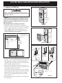
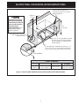
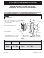
ELECTRIC WALL OVEN INSTALLATION INSTRUCTIONS
INSTALLATION AND SERVICE MUST BE PERFORMED BY A QUALIFIED INSTALLER.
IMPORTANT: SAVE FOR LOCAL ELECTRICAL INSPECTOR'S USE.
READ AND SAVE THESE INSTRUCTIONS FOR FUTURE REFERENCE.
FOR YOUR SAFETY: Do not store or use gasoline or other flammable vapors and liquids in
the vicinity of this or any other appliance.
The first step of your installation should be to measure your current cutout dimensions and compare them
to the cutout dimensions chart below. You may find little or no cabinet work will be necessary.
Do not remove spacers on the side walls and/or on the back of the built-in oven. These spacers
center the oven in the space provided. The oven must be centered to prevent excess heat buildup that may result
in heat damage or fire.
NOTE:
1. Base must be capable of supporting 200 pounds (90.7 kg).
2. Make sure base is level and front of cabinet is square. If the cabinet
base is not level, the oven glides will tend to slide out
when opening the door.
C
** NOTE: Allow at least 23¼" (59.1 cm)
clearance for door depth when it is open.
NOTE: Dimension G is critical to the
proper installation of the built-in oven. If
the oven decorative moulding does not
butt against the cabinet, or if noise is
heard on convection models, verify
dimension G to assure it is according to
the required dimension.
I
11/2"
(3.8 cm)
Min.
4" X 4" (10.2 cm x
10.2 cm) opening to
route armoured
cable.
283/32"
(71.4 cm)
B
G
H
Spacer
F
3" (7.6 cm)
Max.
** Door Open
(see note)
D
31"*
(78.7 cm)
2" (5.1 cm)
Min.
A
* Suggested distance from floor is 31" (78.7 cm).
Minimum required distance is 4½" (11.4 cm).
Electrical
Junction Box
NOTE: For combination of this Built-in Oven with Warm &
Serve Drawer model no E30WD75DSS see cutout dimensions
specified in the Warm & Serve Drawer Installation Instructions.
Figure 1
PRODUCT DIMENSIONS
MODEL
A
B
C (Rear wrapper)
D
30" (76.2 cm) Wall Oven
30 (76.2)
29½ (74.9)
28 (71.1)
241/8 (61.3)
CUTOUT DIMENSIONS AND CABINET WIDTH
MODEL
Min.
30" (76.2 cm) Wall Oven
28½ (72.4)
F Max.
29 (73.7)
G (Min.)
24 (61)
Min.
H Max.
I
281/4 (71.8) 287/8 (73.3)
30 (76.2) Min
All dimensions are in inches (cm).
Printed in the USA
P/N 318201519 (0411) Rev. A
1
English – pages 1-6
Español – páginas 7-13
Français – pages 14-20
ELECTRIC WALL OVEN INSTALLATION INSTRUCTIONS
1. A 3-wire or 4-wire single phase 120/240 or 120/208
Volt, 60 Hz AC only electrical supply is required on
a separate circuit fused on both sides of the line
(time-delay fuse or circuit breaker is recommended).
DO NOT fuse neutral. The fuse size must not exceed
the circuit rating of the appliance specified on the
nameplate. Consideration must be given for a
combination built-in oven and cooktop refer to unit
serial plate of each.
Important Notes to the Installer
1. Read all instructions contained in these installation
instructions before installing the wall oven.
2. Remove all packing material from the oven
compartments before connecting the electrical supply
to the wall oven.
3. Observe all governing codes and ordinances.
4. Be sure to leave these instructions with the consumer.
5. THIS OVEN IS NOT APPROVED FOR STACKABLE OR
SIDE-BY-SIDE INSTALLATION.
NOTE: Wire sizes and connections must conform with
the fuse size and rating of the appliance in accordance
with the American National Electrical Code ANSI/NFPA
No. 70-latest edition, or with Canadian CSA Standard
C22.1, Canadian Electrical Code, Part 1, and local codes
and ordinances.
Important Note to the Consumer
Keep these instructions with your Owner's Guide for future
reference.
IMPORTANT SAFETY
INSTRUCTIONS
An extension cord should not be used
with this appliance. Such use may result in a fire,
electrical shock, or other personal injury.
• Be sure your wall oven is installed and grounded
properly by a qualified installer or service
technician.
• This wall oven must be electrically grounded in
accordance with local codes or, in their absence,
with the National Electrical Code ANSI/NFPA
No.70- latest edition in United Sates, or with CSA
Standard C22.1, Canadian Electrical Code, Part 1, in
Canada.
2. These appliances should be connected to the fused
disconnect (or circuit breaker) box through flexible
armored or nonmetallic sheathed cable. The flexible
armored cable extending from the appliance should
be connected directly to the junction box. The
junction box should be located as shown in figure 1
and with as much slack as possible remaining in the
cable between the box and the appliance, so it can
be moved if servicing is ever necessary.
3. A suitable strain relief must be provided to attach
the flexible armored cable to the junction box.
Stepping, leaning or sitting on the
door of this wall oven can result in serious injuries
and can also cause damage to the wall oven.
• Never use your wall oven for warming or heating
the room. Prolonged use of the wall oven without
adequate ventilation can be dangerous.
Electrical Shock Hazard
• Electrical ground is required on this appliance.
• Do not connect to the electrical supply until
appliance is permanently grounded.
• Disconnect power to the junction box before
making the electrical connection.
• This appliance must be connected to a
grounded, metallic, permanent wiring system,
or a grounding connector should be connected
to the grounding terminal or wire lead on the
appliance.
• Do not use a gas supply line for grounding the
appliance.
The electrical power to the oven must
be shut off while line connections are being made.
Failure to do so could result in serious injury or
death.
1. Carpentry
Refer to figure 1 for the dimensions applicable to your
appliance, and the space necessary to receive the oven.
The oven support surface may be solid plywood or
similar material, however the surface must be level from
side to side and from front to rear.
Failure to do any of the above could result in a
fire, personal injury or electrical shock.
2. Electrical Requirements
This appliance must be supplied with the proper voltage
and frequency, and connected to an individual, properly
grounded branch circuit, protected by a circuit breaker or
fuse, having amperage as noted on the rating plate (the
rating plate is located on the oven frame).
During cold temperature weather to
prevent damage to the oven control, wait at least three
(3) hours after receiving this built-in oven before
switching the power. This will prevent possible damage
to the built-in oven control at power on.
Observe all governing codes and local ordinances
2
ELECTRIC WALL OVEN INSTALLATION INSTRUCTIONS
2. If used in mobile homes or if local codes DO
NOT permit connection of the frame grounding
conductor to the neutral (white) wire, separate
the white and bare copper ground wires that extend
out of the end of the supply cable of the appliance.
Connect the white wire from supply cable to the
neutral white wire in the junction box. Connect the
black and red wires from the supply cable to the
matching color wires in the junction box. The bare
wire must now be used to ground the appliance in
accordance with local electrical codes. Connect the
bare copper ground wire to the grounded lead in the
service panel. DO NOT ground to a gas supply pipe.
DO NOT connect to electrical power supply until
appliance is permanently grounded. Connect the
ground wire before turning on the power (figure 3).
3. Electrical connection
It is the responsibility and obligation of the consumer to
contact a qualified installer to assure that the electrical
installation is adequate and is in conformance with the
National Electrical Code ANSI/NFPA No. 70-latest
edition, or with CSA Standard C22.1, Canadian
Electrical Code, Part 1, and local codes and ordinances.
Electrical ground is required on this appliance.
These appliances are equipped with a copper conductor
flexible cable. If connection is made to aluminum house
wiring, use only special connectors which are approved
for joining copper and aluminum wires in accordance
with National Electrical Code and local codes and
ordinances.
These appliances are manufactured with a white neutral
power supply wire and a frame connected green or bare
copper grounding wire.
Cable from Power Supply
Ground Wire
Red
Wires
1. If local codes permit connection of the frame
grounding conductor to the neutral (white)
wire.
Connect the green (or bare copper) wire and the
white wire from the appliance cable to the supply
cable ground wire (white or bare) inside the junction
box. Connect the remaining wires inside the junction
box from the power supply cable to the matching
colors of the appliance cable wires (figure 2).
Ground Wire
(Bare or Green Wire)
Junction Box
White Wire
Black
Wires
White Wire
U.L.-Listed Conduit
Connector (or CSA listed)
Cable from appliance
Figure 3
4-WIRE GROUNDED JUNCTION BOX
Cable from Power Supply
If connecting to a 4-wire electrical
system, the appliance frame MUST NOT be
connected to the neutral wire of the 4-wire
electrical system.
Black
Wires
Ground Wire
Red
Wires
Junction Box
NOTE TO ELECTRICIAN: The armored cable leads
supplied with the appliance are CSA-recognized for
connection to larger gauge household wiring. The
insulation of the leads is rated at temperatures much
higher than temperature rating of household wiring. The
current carrying capacity of the conductor is governed by
the temperature rating of the insulation around the wire,
rather than the wire gauge alone.
White Wire
Ground Wire
(Bare or Green Wire)
U.L.-Listed Conduit
Connector (or CSA listed)
Cable from appliance
Figure 2
3-WIRE GROUNDED JUNCTION BOX
Improper connection of aluminum
house wiring to copper leads can result in a short
circuit or fire. Use only connectors designed for
joining copper to aluminum, and follow the
manufacturer's recommended procedure closely.
Do not lift the oven by the door handle.
Frame grounded through the neutral.
If used in a mobile home, new branch circuit (1996
NEC) recreational vehicles or where local codes do
not permit grounding through neutral see figure 3.
3
ELECTRIC WALL OVEN INSTALLATION INSTRUCTIONS
4. Cabinet Installation
Heavy Weight Hazard
• Use 2 or more people to move and install wall oven.
• Failure to follow this instructions can result in injury or
damage to the unit.
The wall oven can tip when the door
is open. The mounting brackets supplied with the
wall oven must be attached to the cabinet and the
appliance to prevent tipping of the wall oven and
injury to persons.
1 1/2" (3.8 cm)
clearance
between unit
Mounting Brackets Installation Instructions
1.Unpack the wall oven and find the 2 mounting
brackets and screws included in the literature package.
2.Install the mounting bracket in the cabinet as shown on
figure 4. Note: To prevent damage to cabinet, it is
recommended to drill 1/16" (0.16 cm) dia. pilot holes
before installing the mounting brackets.
Cutout Dimensions
28 1/2" (72.4 cm) Min.*
29" (73.7 cm) Max.*
Mounting
Brackets
23 1/4"
(59.1 cm)
Figure 5
* Recommended
Cutout Width is 28½"
(72.4 cm)
28 1/4"
(71.8 cm) Min.
28 7/8"
(73.3 cm) Max.
Figure 6
1
Oven
Bracket
Mounting
bracket installed
in cabinet
Cabinet
Oven
Figure 4
Right Side
Tool
supplied
3.Insert the unit into the cabinet opening. Slide unit inward
leaving 1 1/2" (3.8 cm) clearance between the oven and
front of cabinet (see Figure 5). Pull the armored cable
through the hole in the floor and toward the junction box
while moving the appliance inward.
2
3
Mounting
bracket released
Oven removed
from the cabinet
4.Push the unit in and against the cabinet, then the oven
side bracket will clip in the one you just install on the side
of the cabinet opening (see figure 6).
To pull out the oven for servicing insert the tool supplied
with the appliance both side at the same time in the hole
located on the side frame and visible when the door is
opened. After inserting the tool pull the oven towards
you (see figure 7).
Hole where to insert
the tool
Figure 7
5.For typical under counter installation of an electric built-in
oven see Figure 8.
4
ELECTRIC WALL OVEN INSTALLATION INSTRUCTIONS
Cabinet side filler panels are
necessary to isolate the unit from
adjoining cabinets.
Approx. 3”
(7.5 cm)
To reduce the risk of personal injury and tipping
of the wall oven, the wall
oven must be secured to
the cabinet (s) by
mounting brackets. Refer
to page 4 for mounting
brackets installation.
36” Min.
(91.4 cm) Min.
G
H
F
208/240 Volt junction box
for built-in oven.
Use 3/4” (1.9 cm) plywood, installed
on two runners, flush with toe plate.
Must be capable of supporting 200
pounds (90 kg).
Cut an opening in wood base minimum 4” x 4”
(10.2 X 10.2 cm), 2” (5 cm) from left side filler
panel, to route armoured cable to junction box.
5” (12.7 cm) Max.
CUTOUT DIMENSIONS
30" (76.2 cm)
Wall Oven
F. WIDTH
G. DEPTH
H. HEIGHT
28 1/2" (72.4 cm) Min.
29" (73.7 cm) Max.
24" (61 cm) Min.
28 1/4" (71.8 cm) Min.
28 7/8" (73.3 cm) Max.
Figure 8- TYPICAL UNDER COUNTER INSTALLATION OF AN ELECTRIC BUILT-IN OVEN
5
ELECTRIC WALL OVEN INSTALLATION INSTRUCTIONS
5. Checking Operation
Model and Serial Number Location
If your model is equipped with an Electronic Oven
Control. Each of the functions has been factory checked
before shipping. However, it is suggested that you verify
the operation of the electronic oven controls once more.
Refer to the Use & Care Guide . Follow the instructions
for the Clock, Timer, Preheat, Bake, Broil Convection
and Clean functions.
The serial plate is located inside the oven on the side
trim.
Bake–After setting the oven to 350°F/177°C for baking,
the lower element in the oven should become red.
Before You Call for Service
When ordering parts for or making inquires about your
oven, always be sure to include the model and serial
numbers and a lot number or letter from the serial plate
on your oven.
Read the Avoid Service Checklist and operating
instructions in your Use & Care Guide. It may save you
time and expense. The list includes common occurrences
that are not the result of defective workmanship or
materials in this appliance.
Broil–When the oven is set to BROIL, the upper element
in the oven should become red.
Clean–When the oven is set for a self-cleaning cycle, the
lower element will become red.
Refer to the warranty in your Use & Care Guide for our
toll-free service number and address. Please call or write
if you have inquiries about your product and/or need to
order parts.
Convection–When the oven is set for a convection,
Convection element located at rear of the oven will turn
on.
IMPORTANT NOTE: A fan inside the oven will turn on as
soon as the oven is operate.
6
Gas Cooktop Installation Over
30" Single Electric Wall Oven
120V/60Hz
grounded
outlet, for
gas cooktop
For all approved gas cooktop models, a minimum
height opening of 6-1/2" (from top of counter) required
in right cabinet side panel and/or filler panel, to route
gas and electric hookups. (Refer to Gas Cooktop
Utility Hookup Diagram)
Cooktop
Manifold
pipe
Flare union
61/2"
min.
5"
Flexible connector
Side filler panels necessary to isolate oven from
adjoining cabinets. Panel height may need to
be modified to accommodate the depth of approved
gas cooktop models
Countertop
18" max.
Manual shutoff valve
(Must be accessible)
Cooktop
cutout**
Side View
Oven cutout
Approx. 3"
36"
min.
Cooktop
28 1/4" min.
28 7/8" max.
24" min.*
240 /208V
Junction box
for wall oven
Gas
Cooktop
Utility
Hookup
Flare
union 120V/60Hz
grounded outlet
Pressure regulator
Cabinet sides
and/or filler panel
4"
Wall Oven
28 1/2" min.
29" max.
24" min.
cutout depth
Install 3/4" full plywood base on 2 runners, flush
with toe plate, capable of supporting 200 lbs.
Unit will overlap cutout (minimum) edges by 1"
4-1/2" maximum height allowed
from oven base to floor if cooktop
is installed directly over wall oven.
(5" maximum height allowed
with no cooktop.)
To route armoured cable to junction box through left cabinet side panel
and/or filler panel, cut minimum 4" x 4" opening in wood base and runner
*Critical dimension – MUST be applied
**For cooktop cutout dimensions refer to model-specific
product installation instructions on the web
Gas Cooktop Installation Over
30" Single Electric Wall Oven Specifications
30" Single Electric Wall Oven Under-Counter
Installation Specifications
Single Wall Ovens are approved to be used beneath Electrolux
ICON™ gas cooktop models E46GC66ESS, E36GC65ESS,
E36GC70FSS and E30GC70FSS (gas cooktop models NOT
approved for use in this installation are E36GC75ESS,
E46GC67ESS, E36GC76EPS, E48GC76EPS and E30GC64ESS.)
• Product
For detailed Gas Cooktop installation specifications, refer to
product-specific section, pages 18-35.
• Side filler panels necessary to isolate oven from adjoining
cabinets. Panel height may need to be modified to
accommodate the depth of approved gas cooktop models.
• Minimum height opening of 6-1/2" (from top of counter)
required in right cabinet side panel or filler panel, to route gas
and electric hookups.
• Allow 4-1/2" maximum height from oven base to floor, if
cooktop is installed directly over wall oven.
Weights –
(E30EW75EPS) 177 Lbs. / (E30EW75ESS) 168 Lbs.
• Single phase 3- or 4-wire cable, 120 / 240 or 120 / 208 Volt,
60 Hertz AC only electrical supply with ground required on
separate circuit fused on both sides of line.
• Connected Load (kW Rating) – 240 / 208 Volts = 4.0 / 3.0 kW
• Amps @ 240 / 208 Volts = 16.6 / 14.4 Amps
• Always consult local and /or national electric codes.
• Minimum 23-1/4" clearance for oven door depth when open.
• Minimum 24" deep, cutout dimension is critical for proper installation. If oven’s face profile does not fit flush against cabinet, or if
noise is heard from oven’s convection system, verify dimension.
• Full oven base of solid plywood or similar material required,
capable of supporting 200 Lbs. Install over two runners and
flush with toe plate.
• Base must be level and cabinet front must be square.
• Side filler panels necessary to isolate oven from adjoining cabinets.
• Allow 5" maximum height from oven base to floor, if NO cooktop
is installed directly over wall oven.
Note: Refer to Product Installation Guides for detailed instructions
on the web at electroluxusa.com.
Electric Cooktop Installation Over
30" Single Electric Wall Oven
For all approved electric cooktop models, cut minimum
4" x 4" opening in right cabinet side panel and/or filler
panel, to route armoured cable to junction box
Side filler panels necessary to isolate oven from
adjoining cabinets. Panel height may need to
be modified to accommodate the depth of approved
electric cooktop models
240 /208V
Junction box
for electric
cooktop
Cooktop
cutout**
Approx. 3"
Oven cutout
Approx. 3"
28 1/4" min.
28 7/8" max.
24" min.*
240 /208V
Junction box
for wall oven
36"
min.
28 1/2" min.
29" max.
24" min.
cutout depth
Install 3/4" full plywood base on 2 runners, flush
with toe plate, capable of supporting 200 lbs.
Unit will overlap cutout (minimum) edges by 1"
4-1/2" maximum height allowed
from oven base to floor if cooktop
is installed directly over wall oven.
(5" maximum height allowed
with no cooktop.)
To route armoured cable to junction box through left cabinet side panel
and/or filler panel, cut minimum 4" x 4" opening in wood base and runner
*Critical dimension – MUST be applied
**For cooktop cutout dimensions refer to model-specific
product installation instructions on the web
Electric Cooktop Installation Over
30" Single Electric Wall Oven Specifications
30" Single Electric Wall Oven Under-Counter
Installation Specifications
Single Wall Ovens are approved to be used beneath Electrolux
ICON™ electric cooktop models E36IC75FSS, E30IC75FSS,
E36EC70FSS and E30EC70FSS (electric cooktop models NOT
approved for use in this installation are E36EC75ESS,
E30EC65ESS and E36EC65ESS.
• Product
For detailed Electric Cooktop installation specifications, refer
to product-specific section, pages 18-35.
• Side filler panels necessary to isolate oven from adjoining
cabinets. Panel height may need to be modified to
accommodate the depth of approved electric cooktop models.
• To route armoured cable to junction box, cut minimum
4" x 4" opening in right cabinet side panel.
• Allow 4-1/2" maximum height from oven base to floor,
if cooktop is installed directly over wall oven.
Weights –
(E30EW75EPS) 177 Lbs. / (E30EW75ESS) 168 Lbs.
• Single phase 3- or 4-wire cable, 120 / 240 or 120 / 208 Volt,
60 Hertz AC only electrical supply with ground required on
separate circuit fused on both sides of line.
• Connected Load (kW Rating) – 240 / 208 Volts = 4.0 / 3.0 kW
• Amps @ 240 / 208 Volts = 16.6 / 14.4 Amps
• Always consult local and /or national electric codes.
• Minimum 23-1/4" clearance for oven door depth when open.
• Minimum 24" deep, cutout dimension is critical for proper installation. If oven’s face profile does not fit flush against cabinet, or if
noise is heard from oven’s convection system, verify dimension.
• Full oven base of solid plywood or similar material required,
capable of supporting 200 Lbs. Install over two runners and
flush with toe plate.
• Base must be level and cabinet front must be square.
• Side filler panels necessary to isolate oven from adjoining cabinets.
• Allow 5" maximum height from oven base to floor, if NO cooktop
is installed directly over wall oven.
Note: Refer to Product Installation Guides for detailed instructions
on the web at electroluxusa.com.