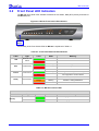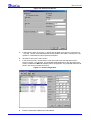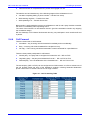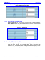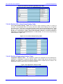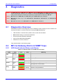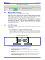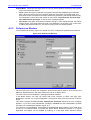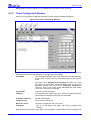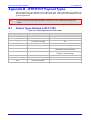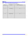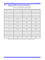
1
MediaPack™ User’s Manual
for MP-124, MP-108, MP-104 and MP-102
VoIP H.323 Gateways
Version 4.2 Beta
Document #: LTRT-00651
US: AudioCodes Inc, 2890 Zanker Road, Suite # 200, San Jose, CA 95134.
Tel: 408-577-0488 - Fax: 408-577-0492
International: AudioCodes Ltd, 4 HaHoresh Street, PO Box 14, Yehud 56470, Israel.
Tel: +972-3-539 4000 - Fax: +972-3-539 4040
China: AudioCodes Ltd, Room 209 Tower A, Grand Pacific Building,
8A Guanghua Road, Chaoyang District, Beijing 100026, P.R.China
Tel: +86-10-6581-6622 - Fax: +86-10-6581-5599
Japan: S Building B1F, 2-30-2, Chuou, Nakano-ku,
Tokyo 164-0011, Japan
Tel: Fax: +81-3-5348-1405 - Fax: +81-3-5348-1405
MP-1xx/H.323 User’s Manual
General
Section
Page
FCC Compliance, Notices, Conformity and Warranty
3
Contents, Figures and Tables
7
1. Overview and Features
13
2. MP-10x Hardware Installation
17
3. MP-124 Hardware Installation
22
4. Software Installation & Upgrade
29
5. Profiling & Operation
39
6. Provisioning
53
7. Network Management
81
8. Diagnostics
99
9. Specifications
105
Appendix A - BootP/TFTP Configuration Utility
111
Appendix B - RTP/RTCP Payload Types
119
Appendix C - DTMF, FAX and Modem Modes
123
Appendix D - DHCP Server Configuration
127
Trademarks
AC, AudioCoded, AudioCodes, AudioCodes logo, IPmedia, Mediant, MediaPack, NetCoder,
Stretto, TrunkPack and VoicePacketizer, are trademarks or registered trademarks of AudioCodes
Limited. All other products or trademarks are property of their respective owners.
Customer Support
Customer technical support and service are provided by AudioCodes’ Distributors, Partners, and
Resellers from whom the product was purchased. For Customer support for products purchased
directly from AudioCodes, contact [email protected].
Abbreviations and Terminology
Each abbreviation, unless widely used, is spelled out in full when first used, and only Industry
standard terms are used throughout this manual. The $ symbol indicates hexadecimal notation.
Documentation
The following AudioCodes manuals should be used for additional information:
“MP-Series H.323 Release Notes”, Document #: LTRT-00652
“VoPLib Reference Library User's Manual”, Document #: LTRT-00744.
Version 4.2 Beta
3
June 2003
MP-1xx/H.323
Notice
This MP-1xx/H.323 User’s Manual describes the AudioCodes MediaPack Series MP-124 24 port, MP108 8-port, MP-104 4-port and MP-102 2-port, referred to collectively as the MP-1xx, supported by
software version 4.2 Beta.
Information contained in this document is believed to be accurate and reliable at the time of printing.
However, due to ongoing product improvements and revisions, AudioCodes cannot guarantee
accuracy of printed material after the Date Published nor can it accept responsibility for errors or
omissions.
© Copyright 2003 AudioCodes Ltd. All rights reserved.
This document is subject to change without notice.
Date Published: Jun-22-2003
Date Printed: Jun-26-2003
FCC Notice to Users
This equipment has been tested and found to comply with the limits for a Class B digital device, pursuant
to part 15 of the FCC Rules. These limits are designed to provide reasonable protection against harmful
interference in a residential installation. This equipment generates, uses and can radiate radio frequency
energy and, if not installed and used in accordance with the instructions, may cause harmful interference
to radio communications. However there is no guarantee that interference will not occur in a particular
installation. If this equipment does cause harmful interference to radio or television reception, which can
be determined by turning the equipment off and on, the user is encouraged to try to correct the
interference by one or more of the following measures:
- Reorient or relocate the receiving antenna.
- Increase the separation between the equipment and receiver.
- Connect the equipment into an outlet on a circuit different from that to which the receiver is connected.
- Consult the dealer or an experienced radio/TV technician for help.
Safety Notice
Installation and service of this Gateway must only be performed by authorized, qualified service
personnel.
MP-1xx/H.323 User’s Manual
4
Document #: LTRT-00651
MP-1xx/H.323 User Manual
General
Telecommunication Safety
The safety status of each port on the Gateway is declared and detailed in the table below:
Ports
Safety Status
Ethernet (100 Base-T)
SELV
FXS
TNV-3
TNV-3: Circuit whose normal operating voltages exceeds the limits for an SELV circuit under normal
operating conditions and on which over voltages from Telecommunication Networks are
possible
SELV:
Safety extra low voltage circuit.
Declaration of Conformity
We AudioCodes Ltd
Declare under our sole responsibility that the products:
MP-1xx/FXS
To which this declaration relates, is in conformity with the following standards: EN 55022 1998,
EN 50024 1998, EN 60950 1992 + Amendments 1, 2, 3 & 4
As described in the European Directives:
89/336 (EMC),
73/23 (Safety),
93/68 (Safety).
Yehud, Israel, 28 Jun 2001
I. Zusmanovich
Compliance Eng.
Este producto està en conformidad con la directiva Europea 89/336, 73/23, 93/68
Dette produkt er i overensstemmelse med Europæiske Direktiver 89/336, 73/23, 93/68
Dieses Produkt ist konform mit der europäischen Richtlinie 89/336, 73/23, 93/68
Ce produit est conforme aux exigences de la Directive européenne 89/336, 73/23, 93/68
Questo prodotto è conforme con la normativa europea 89/336, 73/23, 93/68
Este producto està em conformidade com as Diretrizes Européia 89/336, 73/23, 93/68
Tuote on eurooppalaisen säännöstön mukainen 89/336, 73/23, 93/68
Denna product följer europeiska direktiv 89/336, 73/23, 93/68
Το προιόν, είναι σύµφωνο µε τους κανονισµούς της Ευρωπαικής Κοινώτητας 89/336, 73/23, 93/68
Tæki þetta er í samræmi við tilskipun Evrópusambandsins 89/336, 73/23, 93/68
Dette produktet er i samhørighet med det Europeiske Direktiv 89/336, 73/23, 93/68
Version 4.2 Beta
5
June 2003
MP-1xx/H.323
Note 1: The MP-124 24-port, MP-108 8-port, MP-104 4-port and MP-102 2-port Media Gateways have
similar functionality except for the number of channels (the MP-124 and MP-102 support only
FXS), and all versions are referred to collectively in these release notes as the MP-1xx.
Note 2: MP-10x refers to MP-108 8-port, MP-104 4-port and MP-102 2-port Gateways.
Note 3: MP-1xx/FXS refers only to the MP-124/FXS, MP-108/FXS, MP-104/FXS and MP-102/FXS
Gateways.
Note 4: MP-10x/FXO refers only to MP-108/FXO and MP-104/FXO Gateways.
MP-1xx/H.323 User’s Manual
6
Document #: LTRT-00651
MP-1xx/H.323 User’s Manual
Contents
Table of Contents
1
MP-1xx/H.323 Overview ............................................................................................13
1.1
1.2
1.3
2
Introduction .....................................................................................................................................13
Gateway Description.......................................................................................................................13
MP-1xx Key Features .....................................................................................................................16
MP-10x Hardware Installation...................................................................................17
2.1
Hardware Installation Procedure ....................................................................................................17
2.1.1 Unpacking.............................................................................................................................. 17
2.1.2 MP-10x Rack Mounting Installation ....................................................................................... 18
2.1.3 MP-10x Desktop Mounting Installation.................................................................................. 18
2.1.4 Cable Connections ................................................................................................................ 19
2.1.5 Installation of the MP-10x/FXS Life Line ............................................................................... 19
2.2 Front Panel LED Indicators ............................................................................................................20
2.3 Rear Panel LED Indicators and Connectors...................................................................................21
3
MP-124 Hardware Installation...................................................................................23
3.1
Hardware Installation Procedure ....................................................................................................23
3.1.1 Unpacking.............................................................................................................................. 23
3.1.2 MDF Adaptor ......................................................................................................................... 23
3.1.3 Cable Connections ................................................................................................................ 24
3.1.4 19-inch Rack Mounting for MP-124....................................................................................... 25
3.2 Front Panel LED Indicators ............................................................................................................26
3.3 Rear Panel LED Indicators/Connectors..........................................................................................27
4
Software Installation .................................................................................................29
4.1
4.2
4.3
4.4
Installation Package........................................................................................................................29
MP-1xx Initialization........................................................................................................................29
Quick Setup Procedure...................................................................................................................30
BootP and TFTP Procedures .........................................................................................................32
4.4.1 Configuring the TFTP Server................................................................................................. 33
4.4.2 Using AudioCodes BootP/TFTP Configuration Utility............................................................ 33
4.4.2.1 Configuration Utility Main Features ............................................................................. 33
4.4.3 Configuring the Windows™ NT DHCP Server ...................................................................... 34
4.4.4 Other TFTP & BootP Servers ................................................................................................ 34
4.5 MP-1xx Software Upgrade .............................................................................................................34
4.5.1 General Upgrade Procedure ................................................................................................. 34
4.5.2 Upgrade Procedure Using AudioCodes Configuration Utility................................................ 35
5
Profiling & Operation ................................................................................................39
5.1
H.323 Profile ...................................................................................................................................39
5.1.1 Supported H.323 Features .................................................................................................... 39
5.2 Using H.323 Gateway Features .....................................................................................................41
5.3 Alternate (Redundant) GK Implementation ....................................................................................45
5.4 Working with H.450 Supplementary Services ................................................................................46
5.4.1 Call Hold and Retrieve Features ........................................................................................... 46
5.4.2 Consultation\Alternate Feature.............................................................................................. 46
5.4.3 Call Transfer .......................................................................................................................... 46
5.4.4 Call Forward .......................................................................................................................... 47
5.5 Configuration Examples..................................................................................................................48
5.5.1 Establishing a Call between Two Gateways ......................................................................... 48
5.5.2 Using Two Gateways with Gatekeeper ................................................................................. 48
5.5.3 Using Gateway with NetMeeting™........................................................................................ 48
5.5.4 Remote Extension with FXO & FXS Gateways Example...................................................... 49
5.5.4.1 Dialing from Remote Extension ................................................................................... 50
5.5.4.2 Dialing from other PBX line, or from PSTN ................................................................. 50
5.5.4.3 MP-108/FXS Configuration (using the FXS ini file) ..................................................... 50
5.5.4.4 MP-108/FXO configuration (using the FXO ini file) ..................................................... 51
Version 4.2 Beta
7
June 2003
MP-1xx/H.323
Table of Contents (continued)
6
Provisioning...............................................................................................................53
6.1
Provisioning for H.323 Operation ...................................................................................................53
6.1.1 Basic, Logging and Web Parameters.................................................................................... 54
6.1.2 Channel Parameters.............................................................................................................. 56
6.1.3 H.323 Parameters ................................................................................................................. 59
6.1.4 Loading Configuration Files................................................................................................... 68
6.2 The ini File Structure.......................................................................................................................69
6.2.1 The ini File Structure Rules ................................................................................................... 69
6.2.2 The ini File Example .............................................................................................................. 70
6.3 Excel Utility for ini File Generation..................................................................................................71
6.3.1 General Data Sheet............................................................................................................... 71
6.3.2 End Points Page.................................................................................................................... 72
6.3.3 Phones to IP Routing Table................................................................................................... 72
6.4 Using Call Progress Tones and Ringing.........................................................................................73
6.4.1 Format of the Call Progress ini File ....................................................................................... 73
6.4.2 Default Template for Call Progress Tones ............................................................................ 74
6.4.3 Format of the Ringing Definition ............................................................................................ 77
6.4.3.1 Examples of Various Ringing Signals.......................................................................... 78
6.4.4 Call Progress Tone and Ringing Generation and Download Procedure............................... 79
6.5 The coeff.dat Configuration File .....................................................................................................80
7
Device Management ..................................................................................................81
7.1
SNMP Management .......................................................................................................................81
7.1.1 SNMP Overview .................................................................................................................... 81
7.1.2 SNMP Message Standard ..................................................................................................... 81
7.1.3 SNMP MIB Objects................................................................................................................ 82
7.1.4 SNMP Extensibility Feature................................................................................................... 82
7.1.5 MP-1xx Gateway Supported MIBs ........................................................................................ 83
7.2 Web Management ..........................................................................................................................84
7.2.1 Overview................................................................................................................................ 84
7.2.2 Password Control .................................................................................................................. 84
7.2.2.1 The Embedded Web Server Username-Password ..................................................... 84
7.2.3 Web Configuration................................................................................................................. 84
7.2.3.1 Read-only Mode .......................................................................................................... 84
7.2.3.2 Disable/Enable Embedded Web Server ...................................................................... 84
7.2.4 Using the Embedded Web Server ......................................................................................... 85
7.2.4.1 Set Up Gateway Configuration Parameters ................................................................ 86
7.2.4.2 Set up Gateway Network Parameters ......................................................................... 87
7.2.4.3 Channel Settings ......................................................................................................... 87
7.2.4.4 Configuration File......................................................................................................... 87
7.2.4.5 Regional Settings......................................................................................................... 88
7.2.4.6 Change Password ....................................................................................................... 89
7.2.4.7 Set Up Gateway H.323 Parameters ............................................................................ 89
7.2.4.8 Set Up H.323 Protocol Definition Parameters ............................................................. 90
7.2.4.9 Configuration of Number Manipulation Tables ............................................................ 92
7.2.4.10 Set Up Gateway Endpoints' Phone Numbers.............................................................. 93
7.2.4.11 Set Up Automatic Dialing Table................................................................................... 93
7.2.4.12 Set Up of Caller ID Display Table................................................................................ 94
7.2.4.13 Set Up of Tel to IP Routing Table................................................................................ 94
7.2.4.14 Set Up of IP to Hunt Group Routing Table .................................................................. 95
7.2.4.15 Set Up of Registration Prefixes Table ......................................................................... 95
7.2.4.16 Set Up of Call Forwarding Table ................................................................................. 96
7.2.4.17 Channel Status Menu .................................................................................................. 96
8
Diagnostics ................................................................................................................99
8.1
8.2
Diagnostics Overview .....................................................................................................................99
MP-1xx Gateway Alarms & SNMP Traps .......................................................................................99
8.2.1 LED Visual Indicator Status and Alarms ............................................................................... 99
8.3 MP-1xx Self-Testing .....................................................................................................................100
MP-1xx/H.323 User’s Manual
8
Document #: LTRT-00651
MP-1xx/H.323 User’s Manual
Contents
Table of Contents (continued)
8.4
8.5
RS-232 Terminal...........................................................................................................................100
SysLog Support ............................................................................................................................102
8.5.1 Overview.............................................................................................................................. 102
8.5.2 SysLog Operation................................................................................................................ 102
8.5.2.1 Sending the SysLog Messages ................................................................................. 102
8.5.2.2 Setting the SysLog Server IP Address ...................................................................... 102
8.5.2.3 Controlling the Activation of the SysLog Client ......................................................... 102
8.5.2.4 The ini File Example for SysLog................................................................................ 102
8.6 Solutions to Possible Problems ....................................................................................................103
8.6.1 General ................................................................................................................................ 103
8.6.2 Possible Common Problems ............................................................................................... 103
8.6.3 Possible H.323 Problems .................................................................................................... 104
9
Specifications ..........................................................................................................105
9.1
MP-1xx Specifications ..................................................................................................................105
10 Appendices ..............................................................................................................109
Appendix A
- BootP/TFTP Configuration Utility......................................................111
A.1 Introduction ...................................................................................................................................111
A.1.1 Key Features ....................................................................................................................... 111
A.1.2 Specifications....................................................................................................................... 111
A.1.3 BootP/TFTP Configuration Utility Installation ...................................................................... 112
A.1.4 Logging Screen.................................................................................................................... 112
A.1.5 Preferences Window ........................................................................................................... 112
A.1.6 Client Configuration Window ............................................................................................... 112
A.1.7 Template Window ................................................................................................................ 113
A.2 Window Details .............................................................................................................................114
A.2.1 Main Window ....................................................................................................................... 114
A.2.2 Preferences Window ........................................................................................................... 115
A.2.3 Client Configuration Window ............................................................................................... 116
A.2.4 Templates Window .............................................................................................................. 118
Appendix B
B.1
B.2
B.3
- RTP/RTCP Payload Types..................................................................119
Packet Types Defined in RFC 1890 .............................................................................................119
AudioCodes Defined Payload Types............................................................................................120
Default RTP/RTCP/T.38 Port Allocation.......................................................................................121
Appendix C
- DTMF, Fax & Modem Modes ..............................................................123
C.1 DTMF Relay Settings....................................................................................................................123
C.2 Fax/Modem Settings.....................................................................................................................123
C.3 Configuring Fax Relay Mode ........................................................................................................123
C.4 Configuring Fax/Modem ByPass Mode ........................................................................................124
C.5 Supporting V.34 Faxes .................................................................................................................124
C.5.1 Using Bypass Mechanism for V.34 Fax Transmission ........................................................ 124
C.5.2 Using Relay mode for both T.30 and V.34 faxes................................................................. 125
Appendix D
- DHCP Server Configuration...............................................................127
Windows™ NT DHCP Server Configuration in BootP Compatible (Reserve) Mode..............................127
Version 4.2 Beta
9
June 2003
MP-1xx/H.323
List of Figures
Figure 1-1: MP-124 VoIP Gateway.................................................................................................................. 14
Figure 1-2: MP-108 Front View ....................................................................................................................... 14
Figure 1-3: MP-104 Front View ....................................................................................................................... 14
Figure 1-4: MP-102 Front View ....................................................................................................................... 14
Figure 1-5: Typical MP-1xx VoIP Application .................................................................................................. 15
Figure 2-1: MP-10x Rack Mounting................................................................................................................. 18
Figure 2-2: MP-10x Desktop or Shelf .............................................................................................................. 18
Figure 2-3: RJ-45 LAN and RJ-11 Port Connectors and Pinouts.................................................................... 19
Figure 2-4: RJ-11 Connector and Life Line Pinout for MP-10x/FXS ............................................................... 19
Figure 2-5: MP-10x Front Panel LED Indicators ............................................................................................. 20
Figure 2-6: Rear Panel LED Indicators and Connectors ................................................................................. 21
Figure 3-1: MP-124 in a 19-inch Rack with MDF Adaptor............................................................................... 23
Figure 3-2: 50-pin Telco Connector................................................................................................................. 24
Figure 3-3: RJ-45 and RJ-11 Connectors and Pinouts ................................................................................... 25
Figure 3-4: Front Panel LED Indicators ........................................................................................................... 26
Figure 3-5: Rear Panel LED Indicators and Connectors ................................................................................. 27
Figure 4-1: Web Browser Screen .................................................................................................................... 30
Figure 4-2: H.323 Quick Setup ........................................................................................................................ 31
Figure 4-3: Endpoints' Phone Numbers .......................................................................................................... 31
Figure 4-4: Tel to IP routing table .................................................................................................................... 32
Figure 4-5: AudioCodes Configuration Utility Main Screen ............................................................................. 35
Figure 4-6: Preferences Screen ...................................................................................................................... 36
Figure 5-1: MP-108/FXS & MP-108/FXO Layout ............................................................................................ 49
Figure 6-1: ini File Structure ............................................................................................................................ 69
Figure 6-2: H.323 ini File Example .................................................................................................................. 70
Figure 6-3: General Data Sheet ...................................................................................................................... 71
Figure 6-4: End Points Page ........................................................................................................................... 72
Figure 6-5: Phones to IP Routing Table .......................................................................................................... 72
Figure 6-6: Download Selection Screen .......................................................................................................... 79
Figure 6-7: File Selection Screen .................................................................................................................... 79
Figure 7-1: Embedded Web Server – Home Page.......................................................................................... 85
Figure 7-2: Embedded Web-Server - Gateway Parameters ........................................................................... 86
Figure 7-3: Web Server – Network Settings .................................................................................................... 87
Figure 7-4: Configuration Files ........................................................................................................................ 88
Figure 7-5: Regional Settings ......................................................................................................................... 88
Figure 7-6: Web Server – Change Password.................................................................................................. 89
Figure 7-7: Web Server – Protocol Management Parameters ........................................................................ 89
Figure 7-8: General and Gatekeeper Parameters........................................................................................... 90
Figure 7-9: FXO Gateway Parameters ............................................................................................................ 91
Figure 7-10: Coders......................................................................................................................................... 91
Figure 7-11: DTMF and Dialing Parameters ................................................................................................... 91
Figure 7-12: Fast Start Parameters ................................................................................................................. 91
Figure 7-13: Number of Manipulation and Routing Modes.............................................................................. 92
Figure 7-14: H.450 Supplementary Services .................................................................................................. 92
Figure 7-15: Miscellaneous Parameters.......................................................................................................... 92
Figure 7-16: Phone Number Manipulation Table for IP ! Tel calls ................................................................ 93
Figure 7-17: Endpoint’s Phone Number Table ................................................................................................ 93
Figure 7-18: Automatic Dialing Table .............................................................................................................. 94
Figure 7-19: Caller ID Table ............................................................................................................................ 94
Figure 7-20: Phone to IP Routing & IP Security Table .................................................................................... 95
Figure 7-21: IP to Hunt Group Routing Table.................................................................................................. 95
Figure 7-22: Registration Prefixes Table ......................................................................................................... 95
Figure 7-23: Call Forwarding Table ................................................................................................................. 96
Figure 7-24: Channel Status............................................................................................................................ 96
Figure 7-25: Channel Status Detail ................................................................................................................. 97
Figure 8-1: RS-232 Cable Wiring .................................................................................................................. 100
Figure 8-2: Status and Error Messages......................................................................................................... 101
Figure 8-3: The ini File Example for SysLog ................................................................................................. 102
Version 4.2 Beta
10
June 2003
MP-108 User Manual & Installation Guide
Chapter 1. Overview
Figure 10-1: Main Window............................................................................................................................. 114
Figure 10-2: Preferences Window ................................................................................................................. 115
Figure 10-3: Client Configuration Window..................................................................................................... 116
Figure 10-4: Templates Window.................................................................................................................... 118
Figure 10-5: Scope Menu .............................................................................................................................. 127
Figure 10-6: Add Reserved Clients ............................................................................................................... 128
Figure 10-7: Active Leases Select Screen .................................................................................................... 128
Figure 10-8: Active Leases Selection Box..................................................................................................... 129
Figure 10-9: Client Properties Screen ........................................................................................................... 129
Figure 10-10: DHCP Options: Reservation Screen....................................................................................... 130
Figure 10-11: Active Options ......................................................................................................................... 130
Version 4.2 Beta
11
June 2003
MP-1xx/H.323
List of Tables
Table 2-1: Front Panel Network LED Indicators.............................................................................................. 20
Table 2-2: MP-10x Channel LEDs................................................................................................................... 20
Table 2-3: Meaning of Rear Panel LED Indicators.......................................................................................... 21
Table 2-4: Explanation of Rear Panel Connectors/Switches........................................................................... 21
Table 3-1: Pin Allocation in 50-pin Telco Connector ....................................................................................... 24
Table 3-2: Function of Front Panel LED Indicators ......................................................................................... 26
Table 3-3: Function of Rear Panel LED Indicators.......................................................................................... 27
Table 3-4: Function of Rear Panel Connectors/Switches................................................................................ 28
Table 5-1: Using H.323 Gateway Features (continues on pages 41 to 44) .................................................... 41
Table 6-1: Basic and Logging Parameters (continues on pages 54 to 55) ..................................................... 54
Table 6-2: Channel Parameters (continues on pages 56 to 58) ..................................................................... 56
Table 6-3: H.323 Parameters (continues on pages 59 to 67) ......................................................................... 59
Table 6-4: Call Progress Tones Template (continues on pages 74 to 77)...................................................... 74
Table 8-1: Indicator LEDs on the MP-1xx Front Panel.................................................................................... 99
Table 8-2: MP-1xx Channel LEDs ................................................................................................................. 100
Table 8-3: Possible Common Problems (continues on pages 103 to 103) ................................................... 103
Table 8-4: Possible H.323 Problems ............................................................................................................. 104
Table 9-1: MP-1xx Functional Specifications (continues on pages 105 to 107) ........................................... 105
Table 10-1: Packet Types Defined in RFC 1890........................................................................................... 119
Table 10-2: AudioCodes Defined Payload Types ......................................................................................... 120
Table 10-3: Default RTP/RTCP/T.38 Port Allocation .................................................................................... 121
Note 1: The MP-124 24-port, MP-108 8-port, MP-104 4-port and MP-102 2-port Media Gateways have
similar functionality except for the number of channels (the MP-124 and MP-102 support only
FXS), and all versions are referred to collectively in these release notes as the MP-1xx.
Note 2: MP-10x refers to MP-108 8-port, MP-104 4-port and MP-102 2-port Gateways.
Note 3: MP-1xx/FXS refers only to the MP-124/FXS, MP-108/FXS, MP-104/FXS and MP-102/FXS
Gateways.
Note 4: MP-10x/FXO refers only to MP-108/FXO and MP-104/FXO Gateways.
MP-1xx/H.323 User’s Manual
12
Document #: LTRT-00651
MP-1xx/H.323 User’s Manual
1. Overview
User’s Manual for
MP-102, MP-104, MP-108 and MP-124
H.323 Media Gateways
1
MP-1xx/H.323 Overview
1.1
Introduction
This document provides the User with the information about installation, configuration and
operation of the MP-124 24-port, MP-108 8-port, MP-104 4-port and MP-102 2-port VoIP Media
Gateways. As these units have similar functionality, except for the number of channels and some
minor features, they are referred to collectively as the MP-1xx. It is expected that the readers are
familiar with regular telephony and data networking concepts.
1.2
Gateway Description
The MP-1xx telephony Media Gateway provides excellent voice quality and optimized packet
voice streaming over IP networks. The product enables voice, fax and data traffic to be sent over
the same IP network. It is based on AudioCodes award-winning, field-proven TrunkPack design
using the AudioCodes well-established DSP voice compression technology.
The MP-1xx incorporates up to 24 analog ports for connection, either directly to an enterprise
PBX (MP-10x/FXO), to phones, or to fax (MP-1xx/FXS), supporting up to 24 simultaneous VoIP
calls.
Additionally, the MP-1xx units are equipped with a 10/100 Base-T Ethernet port for connection to
the LAN.
The MP-1xx Gateways are best suited for small to medium size enterprises, branch offices or for
residential Media Gateway solutions.
The MP-1xx Gateways enable Users to make free local or international telephone/fax calls
between the distributed company offices, using their existing telephones/fax. These calls are
routed over the existing IP Internet or Intranet corporate data networks ensuring that voice traffic
takes the minimum of space on the data network.
The MP-1xx Gateways are very compact devices, designed to be installed either as a desk-top
unit (refer to
Figure 1-2) or installed in a 19-inch rack (refer to Figure 2-1).
The MP-1xx supports H.323 ITU, SIP, MEGACO (H.248) and MGCP protocols, enabling the
deployment of "voice over packet" solutions in environments where each enterprise or residential
location is provided with a simple Media Gateway.
This provides the enterprise with a telephone connection (e.g., RJ-11), and the ability to transmit
the voice and telephony signals over a packet network.
Additionally, for emergency use, the MP-10x/FXS Gateway provides a Life Line, connected to the
unused pins on port #4 (or port #2 for MP-102), with a relay to an analog line, even if the
Gateway is powered off.
The layout diagram, Figure 1-5 on page 15, illustrates a typical MP-108 and MP-104 or MP-102
VoIP application.
Version 4.2 Beta
13
June 2003
MP-1xx/H.323
Figure 1-1: MP-124 VoIP Gateway
Figure 1-2: MP-108 Front View
Figure 1-3: MP-104 Front View
Figure 1-4: MP-102 Front View
MP-1xx/H.323 User’s Manual
14
Document #: LTRT-00651
MP-1xx/H.323 User’s Manual
1. Overview
Figure 1-5: Typical MP-1xx VoIP Application
Version 4.2 Beta
15
June 2003
MP-1xx/H.323
1.3
MP-1xx Key Features
"
High quality Voice, Data and Fax over IP networks.
"
MP-124 supports up to 24 analog telephone loop start FXS ports as shown in Figure 1-1 on
page 14.
"
MP-108 supports up to 8 analog telephone loop start FXS or FXO ports as shown in
"
"
Figure 1-2 on page 14.
"
MP-104 supports up to 4 analog telephone loop start FXS or FXO ports as shown in
"
"
Figure 1-3 on page 14.
"
MP-102 supports up to 2 analog telephone loop start FXS ports as shown in
"
"
Figure 1-4 on page 14.
"
Connected to the IP network via a 10/100 Base-T Ethernet interface.
"
Coders include: G.711, G.723.1, G.726, G.727, G.729A and NetCoder at 6.4 to 8.8 kbps,
selectable per channel.
"
T.38 Fax with superior performance (round trip delay up to 9 sec).
"
Compliant with H.323 (Version 4), SIP, MEGACO (H.248) and MGCP.
"
Life Line, connected to the unused pins on port #4 (or port #2 for MP-102), with a relay to an
analog line, even if the MP-10x/FXS is powered off.
"
LEDs on the front and rear panels provide information on the operating Media Gateway
status and of the network interface.
"
Restart button on the Front panel restarts the MP-1xx Gateway
"
MP-10x compact, rugged enclosure providing up to 8 analog RJ-11 ports within a compact
housing of only one-half of a 19-inch rack unit, 1 U high (1.75" or 44.5 mm).
"
MP-124 19-inch, 1 U rugged enclosure provides up to 24 analog FXS ports, using a single
50 pin Telco connector.
"
Mounting option of installing two MP-10x Gateways in a single 19-inch rack shelf, one U high
(1.75" or 44.5 mm).
MP-1xx/H.323 User’s Manual
16
Document #: LTRT-00651
MP-1xx/H.323 User’s Manual
2
2. MP-10x Hardware Installation
MP-10x Hardware Installation
Note 1: The MP-124 24-port, MP-108 8-port, MP-104 4-port and MP-102 2-port Media Gateways have
similar functionality except for the number of channels (the MP-124 and MP-102 support only
FXS), and all versions are referred to collectively in these release notes as the MP-1xx.
Note 2: MP-10x refers to MP-108 8-port, MP-104 4-port and MP-102 2-port Gateways.
Note 3: MP-1xx/FXS refers only to the MP-124/FXS, MP-108/FXS, MP-104/FXS and MP-102/FXS
Gateways.
Note 4: MP-10x/FXO refers only to MP-108/FXO and MP-104/FXO Gateways.
2.1
Hardware Installation Procedure
2.1.1
Unpacking
"
Open the carton and remove packing materials
"
Remove the MP-10x Gateway from the carton
"
Check that there is no equipment damage
"
Check, retain and process any documents
"
Notify AudioCodes of any damage or discrepancies
"
Retain any diskettes or CDs
Safety Notice
Installation and service of this device must only be performed by authorized, qualified service personnel.
Version 4.2 Beta
17
June 2003
MP-1xx/H.323
2.1.2
MP-10x Rack Mounting Installation
Figure 2-1: MP-10x Rack Mounting
The MP-10x is installed into a standard 19-inch rack by the addition of the 2 brackets supplied,
and shown above.
$ To install the MP-10x, take the following steps:
Step 1
Fasten the short bracket to the right-hand side of the MP-10x using the 2 screws
provided, as shown in Figure 2-1, and carefully positioning the peg into a convenient
ventilation hole in the side of the MP-10x box.
Step 2
Fasten the long bracket to the left-hand side of the MP-10x using the 2 screws
provided as shown in Figure 2-1, and carefully positioning the peg into a convenient
ventilation hole in the side of the MP-10x box.
Step 3
Insert the MP-10x into the 19-inch rack and fasten the left-hand and right-hand
brackets to the vertical tracks of the 19-inch rack, using standard 19-inch rack bolts
(not provided).
$ To connect the cables go to Step 4 (Section 2.1.4 on page 19)
2.1.3
MP-10x Desktop Mounting Installation
Figure 2-2: MP-10x Desktop or Shelf
The MP-10x is installed on a desk or shelf without additional brackets as shown above.
$ To connect the cables go to Step 4 (Section 2.1.4 on page 19)
MP-1xx/H.323 User’s Manual
18
Document #: LTRT-00651
MP-1xx/H.323 User’s Manual
2.1.4
2. MP-10x Hardware Installation
Cable Connections
The RJ-45 (Ethernet) and RJ-11 (Ports) pinouts and connectors are shown in Figure 2-3, and
pins are numbered from the left with the latching finger position at the bottom.
Figure 2-3: RJ-45 LAN and RJ-11 Port Connectors and Pinouts
RJ-45 Connector and Pinout
12345678
1 - Tx+
2 - Tx3 - Rx+
6 - Rx-
RJ-11 Connector and Pinout
1234
4, 5, 7, 8
not
connected
1234-
Not connected
Tip
Ring
Not connected
$ To connect the cables for Desk-top or Rack-mount go to Step 4 below:
2.1.5
Note:
Step 4
When using MP-10x/FXS Gateway, insert each of the RJ-11 connectors on the 2-wire
line cords of the POTS phones into the RJ-11 sockets on the rear of the Gateway.
When using MP-10x/FXO Gateway, insert each of the RJ-11 connectors on the 2-wire
line cords coming from PSTN/PBX into the RJ-11 sockets on the rear of the Gateway
Telephone lines and extensions of up to 7,300 m (24,000 ft) can be achieved using
regular 24 AWG line cord.
Step 5
Insert the RJ-45 connector on the 10/100 Base-T cable from your LAN to the ETH RJ45 socket (on the rear of the MP-10x) to provide the link to your LAN.
Step 6
Connect the MP-10x Gateway to the correct AC power supply, and the installation is
now complete.
Installation of the MP-10x/FXS Life Line
The MP-124 and MP-10x/FXO Media Gateways do NOT support the Life Line.
The MP-108/FXS and MP-104/FXS Gateways provide a Life Line connection on port #4.
The MP-102/FXS Gateway provides a Life Line connection on port #2.
This feature provides a wired phone connection to any PSTN or PBX FXS port, upon power-down
conditions. When the power outage occurs, the phone that is connected to the Life Line port (see
above), on pins #2 and #3, is wired to the PSTN or PBX FXS wires on pins #1 and #4 on the
same connector. Therefore, the User of the MP-10x/FXS, can use the phone even when the MP10x/FXS is not powered-on. To use this function, the User must utilize a splitter that connects
pins #1 and #4 to another source of an FXS port, and pins #2 and #3 to the POTS phone.
The pinout of the Life Line RJ-11 phone connector is as follows:
1 = Life Line TIP
2 = TIP
3 = RING
4 = Life Line RING
Refer to Figure 2-4 below for the RJ-11 connector pinout.
Figure 2-4: RJ-11 Connector and Life Line Pinout for MP-10x/FXS
RJ-11 Connector and Life Line Pinout
1234
Version 4.2 Beta
1234-
19
Life Line Tip
Tip
Ring
Life Line Ring
June 2003
MP-1xx/H.323
2.2
Front Panel LED Indicators
The MP-10x front panel LEDs indicate the Ethernet LAN status, Data (RTP) activity and state of
the MP-10x ports.
Figure 2-5: MP-10x Front Panel LED Indicators
Restart
Button
Functionality of the Front Panel LEDs for MP-10x is explained in Table 2-1.
Table 2-1: Front Panel Network LED Indicators
Label
Type
Color
State
Meaning
LAN
Ethernet Link
Status
Green
ON
Valid Connection to 10/100 Base-T hub/switch
Red
ON
Malfunction
Green
Blinking
Transmitting RTP Packets
Red
Blinking
Receiving RTP Packets
Blank
-
No traffic
Green
Blinking
Sending and receiving H.323 messages.
Data
Control
Packet Status
Control Link
Red
Ready
Device Status
Not supported in current release
Green
ON
Device Powered, Self test OK
Orange
Blinking
Software Loading/Initialization
Red
ON
Malfunction
Table 2-2: MP-10x Channel LEDs
MP-10x with 1 to 8 Channels
Label
Activity
Type
Color
State
FXS Tel Port
Green
ON
Off-Hook/Ringing for Phone Port
FXO Line Port
Green
ON
Line-Seize/Ringing State for Line Port
MP-1xx/H.323 User’s Manual
20
Meaning
Document #: LTRT-00651
MP-1xx/H.323 User’s Manual
2.3
2. MP-10x Hardware Installation
Rear Panel LED Indicators and Connectors
Figure 2-6: Rear Panel LED Indicators and Connectors
Chassis
Ground Screw
10/100 Base-T
RJ-45 Port
9-pin RS-232
Status Port
RS-232
1
2
3
4
5
6
7
8
100-250 V ~1A
1 to 8 FXS or FXS Ports
ETH-1
Power Supply
Inlet
8 RJ-11 Ports
FXS or FXS
Table 2-3: Meaning of Rear Panel LED Indicators
Label
ETH-1
Type
Color
State
Meaning
Yellow
ON
Ethernet Port Receiving Data
Red
ON
Collision
Ethernet Status
Table 2-4: Explanation of Rear Panel Connectors/Switches
Label
Type
Function
100-240V ~ 1A
3-pin power inlet
AC input
1 to 8
RJ-11
8 FXS or FXO Ports
MP-108 2-wire Loop Start interface
1 to 4
RJ-11
4 FXS or FXO Ports
MP-104 2-wire Loop Start interface
1 to 2
RJ-11
2 FXS Ports
MP-102 2-wire Loop Start interface
ETH 1
RJ-45
10/100 Base-T Port
RS-232
DB-9, DCE
Status Messages
Gateway connects to PC’s RS-232 port with a
straight cable (refer to Figure 8-1 on page 100).
Grounding screw
Chassis Ground
MUST be securely connected.
Version 4.2 Beta
21
Comment
Connection to external power supply
Shielded
June 2003
MP-1xx/H.323
Reader's Notes
MP-1xx/H.323 User’s Manual
22
Document #: LTRT-00651
MP-124 H.323 User’s Manual
3
3. MP-124 Hardware Installation
MP-124 Hardware Installation
Safety Notice
Installation and service of this device must only be performed by authorized, qualified service personnel.
3.1
Hardware Installation Procedure
3.1.1
Unpacking
$ To unpack the MP-124:
3.1.2
"
Open the carton and remove packing materials
"
Remove the MP-124 from the carton
"
Check that there is no equipment damage
"
Check, retain and process any documents
"
Notify AudioCodes of any damage or discrepancies
"
Retain any diskettes or CDs
MDF Adaptor
To connect 24 2-wire lines into the MP-124, a Main Distribution Frame (MDF) Adaptor Block can
be used as shown in Figure 3-1. This converts the standard RJ-11 connectorized phone line into
a plain pair of wires that are terminated within a 50-pin Telco connector.
Figure 3-1: MP-124 in a 19-inch Rack with MDF Adaptor
19-inch Rack
Rear View
FRONT INPUT
24 line cords
2-wire with RJ-11
connectors
M D F Adaptor Block - rear
REAR OUTPUT
24 wire pairs in
Octopus cable
with 50-pin m ale
Telco connector
Prim ary
LAN Cable
to Eth 1
AC Power Cord
Back-up
LAN Cable
to Eth 2
Connect to
here
ANALO G LINES 1-20
C ntrl
Grounding Strap
Version 4.2 Beta
50-pin fem ale
Telco connector
23
R e ady
ON
RS-232
D ata
100 - 250V~
50 - 60Hz 2A
12345
C O NFIG
Eth 1
Eth 2
MP-124
Rear View
RS-232 Cable
June 2003
MP-1xx/H.323
Note:
The only equipment shown in Figure 3-1 and supplied by AudioCodes is the MP-124 H.323
Gateway and as an option, the MDF Adaptor.
As input (on the front of the 19-inch rack), the Adaptor Block takes in 24 2-wire lines with
standard RJ-11 connectors.
As output (on the rear of the 19-inch rack), the Adaptor Block provides 24 wire pairs, which need
to be terminated into a single 50-pin male Telco connector.
The 50-pin connector must be wired according to the pinout in Table 3-1 and Figure 3-2, shown
below.
3.1.3
Cable Connections
The 50-pin Telco connector mounted on the rear of the MP-124 is wired according to the pinout in
Table 3-1 and Figure 3-2, shown below. The User’s cable-mounted 50-pin Telco connector,
supporting the 24 2-wire phone lines, must be wired identically.
Table 3-1: Pin Allocation in 50-pin Telco Connector
Phone Channel
Connector Pins
Phone Channel
Connector Pins
1
1/26
13
13/38
2
2/27
14
14/39
3
3/28
15
15/40
4
4/29
16
16/41
5
5/30
17
17/42
6
6/31
18
18/43
7
7/32
19
19/44
8
8/33
20
20/45
9
9/34
21
21/46
10
10/35
22
22/47
11
11/36
23
23/48
12
12/37
24
24/49
Figure 3-2: 50-pin Telco Connector
25
Pin N um bers
1
26
50
The RJ-45 (Ethernet) and RJ-11 (POTS) pinouts and connectors are shown in Figure 3-3. Pins
are numbered from the left with the latching finger position at the bottom.
MP-1xx/H.323 User’s Manual
24
Document #: LTRT-00651
MP-124 H.323 User’s Manual
3. MP-124 Hardware Installation
Figure 3-3: RJ-45 and RJ-11 Connectors and Pinouts
RJ-45 Connector and Pinout
12345678
3.1.4
1 - Tx+
2 - Tx3 - Rx+
6 - Rx-
RJ-11 Connector and Pinout
1234
4, 5, 7, 8
not
connected
1234-
Not connected
Tip
Ring
Not connected
19-inch Rack Mounting for MP-124
MP-124 Gateway is supplied with brackets (‘ears’) fitted to each side of the enclosure so that the
MP-124 can be immediately installed in the 19-inch rack.
$ To install the rack mount MP-124, take the next 9 steps:
Step 1
Insert the MP-124 into the 19-inch rack, adjust it to the correct position and use two
standard rack-screws (not supplied) to secure each of the two brackets to the rack
frame.
Step 2
Insert each of the RJ-11 connectors on the 2-wire line cords of the POTS phones into
the RJ-11 sockets on the front of the MDF Adaptor Block
Up to 3,000 m (10,000 feet) of 24 AWG line cord can be used to connect telephones.
Step 3
Attach to the each of the sockets on the rear of the MDF Adaptor Block one pair of
wires from a 25-pair Octopus cable.
Step 4
Connect the wire-pairs at the other end of the Octopus cable to a male 50-pin Telco
connector. The pinout must be that shown in Table 3-1 and Figure 3-2 on page 24.
Step 5
Insert and fasten this 50-pin connector into the female 50-pin Telco connector
mounted at the rear of the MP-124 and labeled Analog Lines 1-24.
Step 6
Insert the RJ-45 connector of the 10/100 Base-T cable into the RJ-45 connector
mounted at the rear of the MP-124 and labeled Eth 1 for connection to your LAN.
Step 7
Connect an electrically grounded strap to the chassis ground screw on the rear of the
MP-124 and fasten it securely according to the current standards.
Step 8
Connect an electric power cord of the correct rating, from a grounded supply of the
correct voltage, into the power socket mounted at the rear of the MP-124 and labeled
100 - 250 V ~ 50 – 60 Hz 2A.
Version 4.2 Beta
25
June 2003
MP-1xx/H.323
Step 9
Observe the front panel LEDs to determine the functioning of the MP-124.
The Channel LEDs indicate that the telephones connected to the rear 50-pin connector are each
in one of the following states:
a. ringing or in the Off Hook position Green
b. normal operation
Blank
c. not functioning
Red
The functions of all the LEDs of the MP-124 are shown in Table 3-2 on page 26.
3.2
Front Panel LED Indicators
Figure 3-4: Front Panel LED Indicators
Reset
Channels
# 1-24
Data
Control
LAN
Ready
Table 3-2: Function of Front Panel LED Indicators
Label
Data
Control
Type
Packet Status
Control Link
Color
State
Green
Blinking
Transmitting RTP Packets
Red
Blinking
Receiving RTP Packets
Blank
-
Green
Blinking
Currently not implemented
Red
ON
Currently not implemented
Orange
LAN
Ready
Channels
# 1- 24
Ethernet Status
Device Status
Tel Port
Tel Status
MP-1xx/H.323 User’s Manual
Function
No traffic
Currently not implemented
Green
ON
Valid link to 10/100 Base-T hub/switch
Red
ON
Malfunction
Green
ON
Device Powered and Self-test OK
Orange
Blinking
Red
ON
Malfunction
Green
ON
Off-Hook/Ringing for FXS Phone Port
Red
ON
Malfunction
Blank
-
26
Software Loading/Initialization
Normal
Document #: LTRT-00651
MP-124 H.323 User’s Manual
3.3
3. MP-124 Hardware Installation
Rear Panel LED Indicators/Connectors
Figure 3-5: Rear Panel LED Indicators and Connectors
Data
LED
Ready
LED
ANALOG LINES 1-20
Ready
50-pin Telco
Connector
ON
Cntrl
100 - 250V~
50 - 60Hz 2A
AC Power
Inlet
LAN
LED
s
RS-232
Data
Grounding
Screw
Monitor
Port
12345
CONFIG
Eth 1
Eth 2
Eth 1 &
Eth 2
Cntrl
LED
Table 3-3: Function of Rear Panel LED Indicators
Label
Data
Cntrl
Ready
Eth 1
Eth 2
Type
Packet Status
Control Link
Device Status
Ethernet Status
Ethernet Status
Version 4.2 Beta
Color
State
Green
ON
Transmitting RTP Packets
Red
ON
Receiving RTP Packets
Blank
-
Green
ON
Currently not implemented
Red
ON
Currently not implemented
Orange
ON
Currently not implemented
Green
ON
Device Powered and Self-test OK
Orange
ON
Software Loading/Initialization
Red
ON
Malfunction
Green
ON
Valid link to 10/100 Base-T hub/switch
Red
ON
Malfunction
Green
ON
Valid link to 10/100 Base-T hub/switch
Red
ON
Malfunction
27
Function
No traffic
June 2003
MP-1xx/H.323
Table 3-4: Function of Rear Panel Connectors/Switches
Label
Type
Function
100-250 V~
50 - 60 Hz 2A
3-pin AC
AC input
Grounding Screw
Chassis ground
50-pin Telco connector
FXS Ports
RJ-45
10/100 Base-T
Shielded port to Ethernet LAN. This is
the default port.
RJ-45
10/100 Base-T
Shielded port to Ethernet LAN.
The port is not in use for current SW
release.
DB-9, DCE
Status Messages
Analog Lines 1 to 24
Eth 1
Eth 2
RS-232
Note:
Comment
Connection to AC power cord
2-wire Loop Start interface
Gateway connects to PC’s RS-232
port with a straight cable (refer to
Figure 8-1 on page 100)..)
The DIP switch located on the MP-124 rear panel is not functional and should not be used.
MP-1xx/H.323 User’s Manual
28
Document #: LTRT-00651
MP-1xx/H.323 User’s Manual
4
4. Software Installation
Software Installation
Note 1: The MP-124 24-port, MP-108 8-port, MP-104 4-port and MP-102 2-port Media Gateways have
similar functionality except for the number of channels (the MP-124 and MP-102 support only
FXS), and all versions are referred to collectively in these release notes as the MP-1xx.
Note 2: MP-10x refers to MP-108 8-port, MP-104 4-port and MP-102 2-port Gateways.
Note 3: MP-1xx/FXS refers only to the MP-124/FXS, MP-108/FXS, MP-104/FXS and MP-102/FXS
Gateways.
Note 4: MP-10x/FXO refers only to MP-108/FXO and MP-104/FXO Gateways.
4.1
Installation Package
The Installation Package includes the following Software and Utilities:
Software:
MP108_ram.cmp
Gateways
- Image Software for download to MP-10x/FXS and MP-10x/FXO
MP124_ram.cmp
- Image Software for download to MP-124 Gateway
usa_tones.dat
- Call progress tones dat file for download
usa_tones.ini
- Call progress tones ini file (used to create dat file)
H323gw_FXS.ini
- ini example file for FXS MP-1xx Gateways
H323gw_FXO.ini
- ini example file for FXO MP-10x Gateways
MP1xx_Coeff_FXS.dat - Telephony interface configuration file for MP-1xx/FXS Gateway
MP10x_Coeff_FXO.dat - Telephony interface configuration file for MP-10x/FXO Gateway
MIB library
- Library of SNMP MIBs
Utilities:
ini file utility.xls - Excel™ utility for creation of ini file
TPDMUtil.exe - Call progress tones file generator utility
Bootp_install.exe
4.2
- AudioCodes BootP & TFTP configuration utility
MP-1xx Initialization
MP-1xx Gateway comes with pre-installed software. The basic installation can be done using
AudioCodes configuration utility, or from Web browser, such as from Microsoft Internet Explorer.
To change network parameters, use Web browser, AudioCodes BootP & TFTP configuration
utility or use third party BootP server.
For setting the H.323 parameters in the ini file, either edit the ini example file, or generate such a
file using the Excel utility provided.
The ini file and other configuration files can be downloaded directly from the Web browser using
either HTTP protocol, or AudioCodes-provided configuration utility or any standard TFTP server.
The Image software file: ram.cmp is only used for software upgrade.
The Call Progress tone file usa_tones.ini is used to define call progress tone levels and their
frequency. To change the tone’s parameters, first modify the file, and then using “TPDMUtil.exe”
Version 4.2 Beta
29
June 2003
MP-1xx/H.323
utility, convert the text ini file to binary dat file. This procedure is described in Section 6.4.
The Coeff_FXS.dat and Coeff_FXO.dat files can be used respectively to modify the MP-1xx/FXS
and MP-10x/FXO telephony interface characteristics, such as DC and AC impedance, feeding
current and ringing voltage. For more information, refer to Section 6.5
4.3
Quick Setup Procedure
The following procedure describes how to setup the MP-1xx Gateway with basic parameters
using standard Web browser (such as Microsoft Explorer). It is assumed that the IP address of
the Gateway is known. If the IP address is unknown, use AudioCodes Configuration utility (or any
standard BootP server) to set the Gateway IP address and subnet mask.
Usually the MP-1xx Gateways are shipped with the following network parameters:
•
MP-1xx FXS Gateway IP address: 10.1.10.10
•
MP-10x FXO Gateway IP address: 10.1.10.11
•
Subnet: 255.255.0.0
•
Default Gateway: 0.0.0.0
$ For quick MP-1xx setup, take the next 12 steps:
1.
Power-up the Gateway; after self-testing, in about 20 seconds the Ready LED on the
front panel turns to green. Any malfunction changes the Ready LED to red.
2.
Before using your Web browser to access the MP-1xx’s Embedded Web Server,
change your PC’s IP address and Subnet Mask to correspond with the MP-1xx’s factory
default IP address and Subnet Mask.
3.
Open any standard Web-browsing application such as Microsoft™ Internet Explorer™
(Ver. 5.0 and higher) or Netscape™ Navigator™ (Ver. 7.0 and higher) and specify the
IP address of the Media Gateway in the ‘Address’ field (e.g., http://10.1.10.10 for FXS);
the Embedded Web Server ‘Enter Network Password’ screen appears, Figure 4-1.
Figure 4-1: Web Browser Screen
4.
Enter the User Name and Password (default: Admin, Admin). Note that the User Name
and Password fields are case-sensitive. Click OK; the ‘Quick Setup’ screen is accessed.
MP-1xx/H.323 User’s Manual
30
Document #: LTRT-00651
MP-1xx/H.323 User’s Manual
4. Software Installation
5.
In the ‘Quick Setup’ screen set the Gateway’s new IP Address, NAT IP Address, Subnet
Mask and Default Gateway IP Address.
6.
Set the basic H.323 Gateway Parameters, as shown in Figure 4-2 below.
Figure 4-2: H.323 Quick Setup
7.
Open the "End Point Phone Number” table and fill in the Gateway phone numbers. For
example, for MP-108, enter “1-8” in ‘Channel(s)’ field and starting Phone number, such
as 101 in adjacent ‘Phone number’ field. The MP-108 physical ports are associated with
phone numbers 101 to 108. You don't need to fill the ‘Hunt Group ID’ column. Click
the Submit button and close the window.
Figure 4-3: Endpoints' Phone Numbers
8.
Version 4.2 Beta
When working without a Gatekeeper the "Tel to IP Routing" table needs to be defined:
Fill in the “Destination phone prefix” (prefix of called number) and the associated IP
address. In the following example, an outgoing (Tel->IP) call with called number starting
with 512 is sent to IP address 10.2.201.11; while all other numbers starting with 51 are
sent to IP address 10.2.201.12. Assuming that the Gateway IP address is 10.2.1.1, all
local calls starting with "10" (such as 101-108) are routed back to the Gateway. When
Gatekeeper is used, the routing table can be used optionally as fallback in case of
failure. Click the submit button and close the window.
31
June 2003
MP-1xx/H.323
Figure 4-4: Tel to IP routing table
9.
Click the ‘RESET’ button and click ‘OK’ in the prompt; wait approx. 60 seconds and
refresh the Web page
10. Restore your PC’s IP address and Subnet Mask to their original values.
11. Using “Advanced Configuration” and “Protocol Management” screens you can modify all
H.323 and other Gateway parameters. Refer to Section 7.2 for detailed directions of
operating under Web management control.
12. Finally you can establish phone calls between phones connected to the Gateway ports
(for FXS Gateway) by dialing 101-108 numbers.
4.4
BootP and TFTP Procedures
If the Gateway IP address is known, you can use Web browser control for Gateway configuration
and provisioning. Otherwise, you can use BootP (or DHCP) and TFTP protocols for initialization
and software download.
Each time the MP-1xx Gateway is powered-on, it performs the standard BootP procedure.
If "DHCPEnable = 1" line is included in Gateway's ini file and if the BootP server was not found,
the Gateway initiates standard DHCP procedure to configure the Gateway network parameters
(IP address, Subnet mask and Default router address). If DHCP procedure is used, you also need
to find the new Gateway IP address allocated by DHCP server. Usually this information can be
provided by System Administrator or you can connect the MP-1xx to PC hyper terminal using RS232 cable and view the Gateway network settings after the Gateway is reset (see chapter 8.4).
If the BootP/DHCP server has not been found, the MP-1xx Gateway starts working from its
internal flash memory.
Usually the application software already resides in the MP-1xx flash memory; therefore there is
no need to use the BootP or TFTP procedure. Their download need only be used for changing
the MP-1xx configuration or for a new software upgrade.
The BootP Protocol enables the network administrators to manage the configuration of the MP1xx Media Gateway from a central configuration server - BootP/DHCP server.
The following RFCs (IETF Requests for Comment) describe BootP in detail: RFC 951, RFC 1542
and RFC 2132.
Downloading of the image file by the MP-1xx is performed using Trivial File Transfer Protocol
(TFTP). TFTP protocol is described in RFC 906 and RFC 1350.
Although DHCP and BootP servers are very similar in operation, the DHCP server includes some
differences that might prevent its operation with BootP clients. However, many DHCP servers,
such as Windows™ NT DHCP server, are backward-compatible with BootP protocol and can be
used for MP-1xx configuration.
Note:
The BootP server is normally used to configure the MP-1xx initial parameters. Once
MP-1xx/H.323 User’s Manual
32
Document #: LTRT-00651
MP-1xx/H.323 User’s Manual
4. Software Installation
this information has been provided, the BootP server is no longer needed. All
parameters are stored in non-volatile memory and used when the BootP server is not
accessible. The BootP server is required again if, for example, the MP-1xx IP address
is to be changed.
Using BootP procedure, the following parameters are configured:
"
Boot & ini File Names
Optional, refer to Note 1 below.
"
Local IP Address
IP address of your MP-1xx Gateway.
"
Gateway IP Address
If Default Gateway/Router is required, otherwise enter 0.0.0.0
address.
"
Subnet Mask
Subnet Mask of your MP-1xx Gateway.
"
TFTP Server IP Address
Refer to Note 2 below.
Note 1:
Boot file name can contain one or two file names. ram.cmp file name to be used for download of
application image and mp1xx.ini file name to be used for MP-1xx provisioning. Either one, two
or no file names can appear in the Boot file name field. To use both file names use ";" separator
(without blank spaces) between the xxx.cmp and the yyy.ini files (e.g., ram.cmp;H323gw.ini).
Note 2:
Usually TFTP and BootP servers are installed on the same Host. However, when using
AudioCodes Configuration utility or Microsoft™ DHCP server, it is possible to set the IP address
of TFTP server (Boot Server Host Name field), and in this case BootP and TFTP servers can
run from different Hosts.
4.4.1
Configuring the TFTP Server
$ To configure the TFTP Server, take the next 4 steps:
4.4.2
1.
Set the default directory where the image file resides (C:\AudioCodes\…).
2.
Copy the Image file (such as ram.cmp to the TFTP default directory on your Host PC.
3.
Copy the ini file and other optional configuration files (Call Progress tones and Coeff.dat
files) to the TFTP default directory on your Host PC. Ensure correct coeff.dat file is
used. Two different coefficient files are provided, for MP-1xx/FXS and MP-10x/FXO.
4.
Set the TFTP timeout to 3 seconds and number of retransmissions to 20.
Using AudioCodes BootP/TFTP Configuration Utility
The AudioCodes Configuration utility provides an easy way to configure the MP-1xx Gateway.
Similar to other BootP and TFTP servers, the application can be installed on Windows™ 98 or
Windows™ NT/2000. With AudioCodes’ BootP/TFTP Server Configuration utility, it is possible to
use the integrated TFTP server (part of the Utility) or to install TFTP server on a different host.
The utility enables remote reset of the MP-1xx unit for triggering the initialization procedure
(BootP & TFTP). For details of the procedure, refer to Appendix A - BootP/TFTP Configuration
Utility.
4.4.2.1
Configuration Utility Main Features
"
BootP server supporting hundreds of entries.
"
Integrated TFTP server.
"
Common Log window displaying BootP and TFTP status.
"
Contains all data required for provisioning of AudioCodes products.
"
Provides the TFTP server address, enabling network separation of TFTP and BootP servers.
"
Tools for backup and for restoring the local database.
Version 4.2 Beta
33
June 2003
MP-1xx/H.323
4.4.3
"
Templates.
"
User-defined names for each entity.
"
Protection against entering fault information.
"
Unicast or Broadcast BootP response.
Configuring the Windows™ NT DHCP Server
If Microsoft™ Windows NT DHCP server is used in your organization, the server can be used in
reservation mode to provide an IP address and other necessary information to the MP-1xx Media
Gateway.
To configure the Microsoft™ Windows™ NT DHCP Server to assign IP address information to
BootP clients, add a reservation for each BootP client.
For information about how to add a reservation, view the "Managing Client Reservations Help"
topic in DHCP Manager.
The reservation builds an association between the media access control address (12 digits,
provided in MP-1xx documentation) and the IP address. Windows™ NT Server provides the IP
address based on the MP-1xx media access control (MAC) address in the BootP request frame.
To configure the Microsoft™ Windows™ NT DHCP server to provide boot file information to BootP
clients, edit the BootP Table in DHCP Manager. The BootP Table is located in the Server
Properties dialog box that can be accessed from the Server menu. For information about how to
edit the BootP Table, view the "BootP Table" Help topic in DHCP Manager.
The following parameters must be entered:
Note:
"
Local IP address
IP address of your MP-1xx Gateway.
"
Subnet mask
Refer to Section 4.4 Note 2, for the mask limits.
"
Gateway IP address
Default Gateway IP address
"
Boot File name
Optional, refer to following Note.
Boot file name normally should not be used. This field is only used for software upgrade (refer to
Section 4.5.
Refer to Utilities User Manual for detailed description of configuration of Windows NT DHCP
server.
4.4.4
Other TFTP & BootP Servers
Third party TFTP and BootP servers can be used; for example Weird Solutions™ (www.weirdsolutions.com).
4.5
MP-1xx Software Upgrade
4.5.1
General Upgrade Procedure
MP-1xx includes on-board flash memory already programmed with application software. The
following procedure replaces the old stored software with the new version. To run this procedure
BootP and TFTP servers are required. Web browser can be used instead of BootP server (refer
to Section 7.2).
Note1:
The file extensions cmp and ini should be written in lower case letters.
Note2:
When upgrading the internal software (either from a TFTP Server or from the Embedded Web
Server) it is mandatory to download the ram.cmp file and all other related files: ini, coefficient
and call progress tone.
MP-1xx/H.323 User’s Manual
34
Document #: LTRT-00651
MP-1xx/H.323 User’s Manual
4. Software Installation
$ To upgrade the integral Software take the next 5 steps:
Note:
4.5.2
1.
Start the TFTP and BootP servers, refer to Appendix A.
2.
Copy the new ramxxx.cmp file, mp108.ini file (e.g., H323gw.ini) and optional
configuration files to the default TFTP server directory.
3.
Set the Boot file and ini file names in the Web browser Network settings page or in the
BootP server: ramxxx.cmp -fb;mp108.ini. Other network parameters stay unchanged (IP
address, subnet mask,…). If so required, it is possible to update only the mp108.ini
parameters. For this option, set the boot file name to: mp108.ini (without preceding
ramxxx.cmp). After MP-1xx power reset, the ini parameters are downloaded using the
TFTP procedure and stored in the non-volatile memory.
4.
Reset the MP-1xx. Wait about 20 seconds until the Ready LED changes to Green.
5.
After accomplishing BootP and TFTP procedures, the new software is downloaded and
stored in the MP-1xx unit’s flash memory.
The parameter “-fb” added to Boot file name is used to specify the burning of flash
memory with new software image. To test new software version without replacing the
old version, skip the “-fb” parameter. In this case, the new software is downloaded
directly to RAM, and not permanently stored into flash.
Upgrade Procedure Using AudioCodes Configuration Utility
The following procedure describes how to upgrade the MP-1xx software using the AudioCodes
configuration utility.
$ To upgrade the Software using the AudioCodes Configuration Utility
take the next 13 steps:
1.
Install AudioCodes’ Configuration utility from the AudioCodes Software CD, Document #
LSTC00005 (MediaPack Series).
2.
Open the AudioCodes Configuration utility from Start>Programs>BootP; the
AudioCodes Configuration utility main screen opens:
Figure 4-5: AudioCodes Configuration Utility Main Screen
3.
Click on the Edit tab to open the Edit menu.
4.
Select Preferences to open Preferences window shown below 36.
Version 4.2 Beta
35
June 2003
MP-1xx/H.323
Figure 4-6: Preferences Screen
5.
In the Directory field, click on the >> button and navigate to the directory of the source
*.cmp and *.ini files. All downloaded files should reside in this folder, including ram.cmp,
mp108.ini, Coeff.dat and Call Progress tone.dat files.
6.
Click OK to return to the main screen.
7.
In the Services menu, choose Clients. This opens the Client Configuration screen
shown in Figure 4- on page 36. The parameter fields displayed on the right side of the
screen constitute the MP-1xx software profile configuration. The parameter fields are all
blank in the case of a Client Not Found.
Figure 4-7: Client Configuration
8.
Enter the Client MAC address and Client Name.
MP-1xx/H.323 User’s Manual
36
Document #: LTRT-00651
MP-1xx/H.323 User’s Manual
9.
4. Software Installation
Enter the IP address (such as 10.2.37.1).
10. Enter the Subnet (such as 255.255.0.0); set the Subnet to a valid value in accordance
with the IP address.
11. Enter the IP address of the default Gateway; it can be any address within the subnet.
12. Select the required Boot and ini Files
13. To permanently store the new image file in the MP-1xx flash memory, add –fb suffix to
Boot file name, such as “ram.cmp –fb”. After entering the file names, click “Apply &
Reset” button.
The following status messages is displayed in the AudioCodes BootP/TFTP Server main screen:
Figure 4-8: AudioCodes Configuration Utility – TFTP download
Version 4.2 Beta
37
June 2003
MP-1xx/H.323
Reader's Notes
MP-1xx/H.323 User’s Manual
38
Document #: LTRT-00651
MP-1xx/H.323 User’s Manual
5
5. Profiling & Operation
Profiling & Operation
Note 1: The MP-124 24-port, MP-108 8-port, MP-104 4-port and MP-102 2-port Media Gateways have
similar functionality except for the number of channels (the MP-124 and MP-102 support only
FXS), and all versions are referred to collectively in these release notes as the MP-1xx.
Note 2: MP-10x refers to MP-108 8-port, MP-104 4-port and MP-102 2-port Gateways.
Note 3: MP-1xx/FXS refers only to the MP-124/FXS, MP-108/FXS, MP-104/FXS and MP-102/FXS
Gateways.
Note 4: MP-10x/FXO refers only to MP-108/FXO and MP-104/FXO Gateways.
5.1
H.323 Profile
5.1.1
Supported H.323 Features
The MP-1xx Gateway implements RadVision™ H.323 version 4.0 protocol stack. In this version,
the Gateway features the following:
Gatekeeper:
"
Can work without Gatekeeper (use internal phone table).
"
Can register to known Gatekeeper.
"
MP-1xx can function as an H.323 Gateway or it can imitate an H.323 terminal with multiple
aliases (e.g., up to eight for MP-108).
"
Supports GK registration with prefixes
"
Can use routed-mode calls.
"
Can use direct-mode calls.
"
Redundant Gatekeepers can be defined in ini file
"
Fallback to internal routing table if no communication with GK
"
"TimeToLive" parameter is supported. The MP-1xx Gateway sends Registration requests up
to "TimeToLive" expiration.
"
IRR messages for KeepAlive are supported.
"
Supporting mapping of destination (Alias) number in ACF message by Gatekeeper.
"
Supporting RAI (Resource Available Indication) messages, informing gatekeeper that the
Gateway resources are below a threshold.
Call setup:
"
Can use Normal Connect procedure.
"
Can use Fast Connect procedure with or without opening immediately H.245 channel.
"
Can use Tunneling.
"
Can negotiate codec from a list of given codecs for Normal or Fast Connect procedures.
"
Optional opening of H.245 channel when using Fast Connect.
Version 4.2 Beta
39
June 2003
MP-1xx/H.323
Other:
"
Country Code (0xB5) and Manufacturers Code (0x28) are used in H.323 messages
"
Support H.323 Annex D, T.38 real time FAX.
"
Supports H.450 Call Hold, Call Transfer and Call Forwarding supplementary services
(H.450.1, H.450.2, H.450.3 and H.450.4).
"
Supported codecs: G.711 A-law (5, 10 and 20 msec), G.711 µ-law (5, 10 and 20 msec),
G.723 (5.3 and 6.3 kbps), G.729 (8 kbps, 10 and 20 msec), G.726 (16, 32 kbps, 20 msec),
NetCoder (6.4, 7.2, 8.0 and 8.8 kbps, 20 msec).
"
Supports DTMF and HookFlash signal out of band using H.245 channel (using
"Alphanumeric" field).
"
Supports DTMF and HookFlash signal out of band using H.225/Q.931 keypad facility
messages
"
Support of one or two stage dialing for network to PBX/PSTN calls, using MP-10x/FXO
Gateway.
"
Support of collecting Digits from PBX by MP-10x/FXO Gateway.
"
Gateway registration with prefixes (applicable to FXO Gateway)
"
Reopening of logical channel and implementation of empty terminal capability set.
"
Configurable H.323 Port Range.
"
H.225/Q.931 Progress Indicator parameter is supported for Fast Connect, enabling playing
of local ringback tone or to cut through the voice channel to listen to remote call progress
tones/messages.
"
Supports detection of Caller ID signal (Bellcore and ETSI standards) from PBX line by MP10x/FXO Gateway, and interworking it to H.323 network.
For detailed information, refer to the latest MP-1xx/H.323 Release Notes, Document #: LTRT00652.
MP-1xx/H.323 User’s Manual
40
Document #: LTRT-00651
MP-1xx/H.323 User’s Manual
5.2
5. Profiling & Operation
Using H.323 Gateway Features
Details of how to use and configure the H.323 Gateway Parameters (from ini file) are shown
below in Table 5-1.
Table 5-1: Using H.323 Gateway Features (continues on pages 41 to 44)
Feature
Parameter
Sheet of Excel
Utility
H323gw
Value
Use given
Gatekeeper
IsGatekeeperUsed
1
GatekeeperIp
H323gw
Single IP address or several IP address if redundant
gatekeeper option is enabled.
IP
Redundant
Gatekeepers
IsRedundantGKUsed
H323gw
Specify list of gatekeeper IP addresses using
GatekeeperIp parameter. Gateway starts working
with first GK from the list. In case of a failure with first
GK, the Gateway tries to find other GKs from the list.
Once GK is found, the Gateway continues working
with it, until the next failure. If none of the GKs
respond, Gateway goes over the list again.
1
No
Gatekeeper,use
routing table
IsGatekeeperUsed
H323gw
0
Define routing table using:
a. PREFIX = prefix, <IP address> list
b. Prefix = *, <IP address>
Routing or/&
Prefix Tables
Phone
numbers,
Prefixes and
IPs
When Gatekeeper isn’t used, it is necessary to define IP routing table, to enable MP1xx Gateway to find destination IP address, according to received dial number. The
routing table is defined in ini file, using PREFIX or per phone number definitions.
The Gateway first searches for Phone table to find a destination IP address, than it
looks for Prefix parameter, and later for ”Prefix = *,<IP address>" definition.
“Prefix = *, <IP address>“ defines destination IP address for any other phone number.
Fall Back to
internal routing
table
IsGKFallbackUsed
H323gw
Gateway starts using internal routing table (phone to
IP, or prefix to IP) if communication with Gatekeeper
is lost. Gateway returns to Gatekeeper when
communication is restored.
1
Set numbers to
end points
Channel2Phone= <channel>,<phone>
or ChannelList = port, number, phone
Phone
numbers
EndPoints
The easiest way to define endpoint phone number is to use ChannelList parameter. For
example, to define 101 to 107 numbers for an MP-108, use a single line: ChannelList =
0,8,101.
The first parameter (0) indicates the first endpoint number.
The second parameter (8) indicates the number of endpoints.
The third parameter (101) indicates the first endpoint phone number.
Up to ten such ChannelList definitions can appear in the same ini file.
One or more phone numbers in the ChannelList can be modified by using
Channel2Phone definition, following the ChannelList parameter in the ini file.
Dial plan
Use “Fast
Connect”
Version 4.2 Beta
MaxDigits
Maximal number of digits in dialed number.
General
Max digits
TimeBetweenDigits
Timeout between dialed digits, used to terminate
dialing. Usually it is set to 4 seconds.
General
Time in
seconds
IsFastConnectUsed
H323gw
1
41
June 2003
MP-1xx/H.323
Table 5-1: Using H.323 Gateway Features (continues on pages 41 to 44)
Feature
Parameter
Sheet of Excel
Utility
Value
procedure
Fast start and Tunneling can be used together
Use “Tunneling”
procedure
IsTunnelingEnabled
H323gw
1
Default number
DefaultNumber
General
Default number
This is used to get call setups from end-points that do not send called phone number.
Automatic dialing IsDialNeeded
TargetOfChannel
General
0
Automatic
Dialing
Phone
numbers to dial
This is used to perform automatic dialing once OFF HOOK is detected in FXS Gateway
or ringing is detected in FXO port. There is no need to dial in this mode.
For each channel, define destination phone number, using
“TargetOfChannel<channel> = phone number” definition.
Choose Coder
CoderName
General
Preferred coder
name
Several Coders
CoderName
General
List of coders
In this mode, several codecs are sent in capabilities message. After negotiation with
the remote side a single coder will be selected for transmit and receive.
Annex D Fax
One Stage
Dialing,
IP ! FXO calls
IsFaxUsed
Channel
1
To use Annex D Fax, configure:
UseT38orFRF11 = 1 (T.38)
FaxTransportMode =1 (relay)
Fax
To improve Fax transmission over congested IP
network, use optional redundancy parameters:
FaxRelayEnhancedRedundancyDepth = N
FaxRelayRedundancyDepth =M
N = 0 to 4
M = 0 to 2
Channel
IsTwoStageDial
H323gw
0
IsUseFreeChannel
General
1
ports
MP-10x/FXO seizes the next available FXO line, and General
dials the destination phone number received in Setup
message. Use the ‘IsWaitForDialTone’ parameter to
specify whether the dialing comes after detection of
dial tone, or immediately after seizing the line.
MP-10x/FXO supports registration of prefixes to
Gatekeeper. If your gatekeeper doesn’t support the
Gateway’s prefix registration, you can probably
configure the Gatekeeper to enable routing of Call
with destination phone number to correct MP10x/FXO IP address. Usually this is done by
allocating telephone numbers range or prefix to MP10x FXO IP address.
The FXO Gateway releases the call if busy or fast
busy (reorder) tone is detected on the FXO port.
MP-1xx/H.323 User’s Manual
42
Document #: LTRT-00651
MP-1xx/H.323 User’s Manual
5. Profiling & Operation
Table 5-1: Using H.323 Gateway Features (continues on pages 41 to 44)
Feature
Two Stage
Dialing,
IP ! FXO calls
Parameter
IsTwoStageDial
IsUseFreeChannel
Sheet of Excel
Utility
Value
H323gw
General
1
1
H323gw
Channel
Channel
H323gw
H323gw
H323gw
1
0
0
0
1
1
For ‘Two Stage Dialing’ the MP-10x/FXO seizes the
next available PSTN/PBX line, without performing
any dial, the remote user is connected over IP to
PSTN/PBX, and all further signaling (dialing and call
progress tones) is done directly with the PBX without
Gateway intervention.
Usually the phone number received in Setup
message is not used, however
if ‘IsUseFreeChannel = 0’, the phone number
received in Setup, is used for seizing specific FXO
line that has same number.
Refer to the remote extension application note.
The FXO Gateway releases the call if busy or fast
busy (reorder) tone is detected on the FXO port.
Using out of band
DTMF signaling
over H.245 and
HookFlash
signaling
IsDTMFUsed
DTMFTransportType
DTMFDetectionPoint
Is931MsgUsed
IsHookFlashUsed
OpenH245onFS
When using H.245 out of band signaling, disable
inband signaling (mute and don’t relay the digits). In
addition, disable the Q.931 sending.
Using “DTMFVolume = “ set the level of played
DTMF digits.
The HookFlash signal is detected at FXS endpoints
and generated at FXO endpoints, according to
“FlashHookPeriod = “ parameter.
Note: When using Fast Start the H.245 channel
remains close, and out of band signaling can’t be
used, unless “OpenH245onFS” is set to 1 or remote
Gateway/terminal opens the H.245 channel.
Channel
H323gw
Open media only
on connect
IsFSOpenMediaONConnect
H323gw
Using Hunt
Groups
TrunkGroup_x = a-b, <starting number>
IsUseFreeChannel
PSTNPrefix = <prefix>, <Hunt Group ID>
AddTrunkGroupAsPrefix
0
This feature is useful when Tunneling or Fast Connect are used. Voice channel in
egress Gateway is opened immediately after sending an ALERT message. If this is not
the appropriate procedure, the User can set this parameter to “1”. to open voice
channel only after CONNECT is sent.
TG
General
TGRoute
range
1
0
This feature can be used to define group of Gateway
ports, called hunt groups. For example:
TrunkGroup_1 = 1-4,100
TrunkGroup_1 = 8,200
TrunkGroup_2 = 5-7,300
Version 4.2 Beta
43
June 2003
MP-1xx/H.323
Table 5-1: Using H.323 Gateway Features (continues on pages 41 to 44)
Feature
Parameter
Sheet of Excel
Utility
Value
To use the hunt groups it is required to define also
"IsUseFreeChannel=1" , and to define routing rules,
using "PSTNPrefix" parameter.
The routing IP!TEL rules define per each called
number prefix, the Hunt Group ID where the call will
be send to. For example:
PSTNPrefix = 101,1
Incoming IP!TEL call, with called number starting
with 101 will select free channel from 1st Hunt group.
Usually this feature will be used for FXO Gateways,
but there are some hunt groups applications also
with FXS Gateways.
"AddTrunkGroupAsPrefix = 1" can be used when
incoming Tel!IP call should be treated differently
according to received hunt group. If this feature is
enabled the Hunt group ID is added to called number
as a prefix. The number manipulation and routing
(Prefix=) rules will apply to the new destination
number.
Note: When using Trunk groups don't use
"ChannelList" or "Channel2Phone" parameters .
MP-1xx/H.323 User’s Manual
44
Document #: LTRT-00651
MP-1xx/H.323 User’s Manual
5.3
5. Profiling & Operation
Alternate (Redundant) GK Implementation
1.
The MP-1xx Gateway doesn’t support Automate Gatekeeper discovery. Gatekeeper address
is provided through initialization file (or via Web management). In AudioCodes, this
procedure is referred to as “Redundant Gatekeeper” procedure. In general, it is identical to
Alternate procedure described in H.323 standard, with the exception that the list of primary
and alternate Gatekeepers is provided via initialization file.
2.
In addition to primary Gatekeeper address, it is possible to provide list of two additional,
“Alternate” Gatekeeper addresses, using the same initialization file.
3.
Working with primary and alternate gatekeepers is according to procedure described in the
H.323 standard (para. 7.2.6 Alternate gatekeeper procedures), with the exception that all
Alternate Gatekeeper fields in RAS messages are ignored.
4.
According to H.323, para 7.2.6 procedure, the MP-1xx Gateway supports the following:
"
"
Endpoint attempts to register with the Gatekeeper using the list of Alternate Gatekeepers.
If the endpoint is registered with the Gatekeeper and the Gatekeeper becomes
unresponsive, the endpoint shall attempt to communicate with an Alternate Gatekeeper.
If the endpoint determines that a temporary Alternate Gatekeeper is unresponsive, it
attempts to retransmit the RAS request to another Alternate Gatekeeper. If all Alternate
Gatekeepers are unresponsive to a RAS request, the endpoint assumes that the RAS
request is rejected.
"
5.
If an MP-1xx Gateway finds an alternative Gatekeeper from the list of alternate
Gatekeepers, it registers with this Gatekeeper and continues working with it until next failure
(current GK is not responding).
6.
If all Gatekeepers are unresponsive, the MP-1xx Gateway tries again to establish
communication, and to register to the first gatekeeper according to the provisioned
Gatekeeper list.
7.
The MP-1xx Gateway has an option to use internal phone to IP routing table (Fallback
mode), when all Alternative Gatekeepers are unresponsive. If this option is enabled, MP-1xx
starts using its internal routing table, and works without Gatekeeper. The MP-1xx leaves this
Fallback mode as soon as it finds again a responsive Gatekeeper from its list of the
Gatekeepers.
8.
Alternate Gatekeeper, using RAS IRQ message, can retrieve the state of existing calls. The
MP-1xx Gateway responds via IRR message.
Version 4.2 Beta
45
June 2003
MP-1xx/H.323
5.4
Working with H.450 Supplementary Services
H.323 MP-1xx FXS and FXO Gateways support the following supplementary services:
"
Hold\Retrieve ( H.450.4).
"
Consultation\Alternate.
"
Transfer (H.450.2).
"
Call forward (H.450.3).
To activate supplementary services on MP-1xx Gateway you should Enable Hold, Transfer and
Forward services either from Web browser or in ini file. To use these features all participated, in a
call, H.323 endpoints should comply to the H.450.1-4 standards.
5.4.1
5.4.2
5.4.3
Call Hold and Retrieve Features
"
The active call can be put into Hold state by pressing phone's hook-flash button.
"
The party that initiates the hold is called the holding party, the other party is called the held
party.
"
After a successful hold, the held party should hear HELD_TONE and the holding party
should hear DIAL_TONE.
"
Retrieve can be performed only by the holding party while the call is held and active.
"
The holding party performs the retrieve by pressing the hook flash.
"
After a successful retrieve the voice should be connected again.
Consultation\Alternate Feature
"
The consolation feature is relevant only for the holding party (applicable only for MP-1xx FXS
Gateway).
"
After holding a call (by pressing hook flash) the holding party hears dial tone and may now
initiate a new call which is called a consultation call.
"
At the stage of hearing dial tone or dialing to the new destination (before completing the
dialing) the user may retrieve the held call by pressing the hook flash.
"
The held call can’t be retrieved while hearing ring back tone.
"
After the consultation call is connected, the user may switch between the held and active call
by pressing the hook flash.
Call Transfer
There are two types of call transfers:
"
Consultation Transfer
"
Blind Transfer
The common way to perform a consultation transfer is as follows:
In the transfer scenario there are three parties:
A - transferring, B – transferred, C – transferred to.
1.
A Calls B.
2.
B answers.
3.
A presses the hook flash and puts B on hold (party B will hear a hold tone)
4.
A dials C.
5.
After A completed dialing C , he can perform the transfer by on-hook the A phone.
MP-1xx/H.323 User’s Manual
46
Document #: LTRT-00651
MP-1xx/H.323 User’s Manual
6.
5. Profiling & Operation
After the transfer is completed B and C parties are engaged in a call.
The transfer can be initiated at any of the following stages of the call between A to C:
a. Just after completing dialing C phone number - Transfer from setup.
b. While hearing ring back – Transfer from alert.
c.
While speaking to C – Transfer from active.
Blind transfer is performed after we have a call between A and B, and A party decides to transfer
the call to C immediately without speaking with C.
The result of the transfer is a call between B and C (just like consultation transfer only skipping
the consultation stage).
MP-1xx Gateways can’t initiate a blind transfer but they can participate in such transfer as B and
C parties.
5.4.4
Call Forward
There are three kinds of call forwards:
1.
Immediate – Any incoming call will forwarded immediately and unconditionally.
2.
Busy – Incoming call will be forwarded if the endpoint is busy.
3.
No reply – The incoming call will be forwarded if it wasn't answered for a specified time.
There are three parties participated in call forward:
1.
Served party – the party that is configured to forward the call – MP-1xx FXS.
2.
Originating party – the party that initiated the first call – MP-1xx FXS or FXO.
3.
Diverted party – the new destination of the forwarded call – MP-1xx FXS or FXO.
The served party (MP-1xx FXS) can be configured from Web browser or ini file to activate one of
the call forward modes per each of the Gateway's endpoint, including forwarded destination
phone number and "no answer" timeout for "No reply" forward.
Figure 5-1: Call Forwarding Table
Version 4.2 Beta
47
June 2003
MP-1xx/H.323
5.5
Configuration Examples
Note 1: The MP-124 24-port, MP-108 8-port, MP-104 4-port and MP-102 2-port Media Gateways have
identical functionality (the MP-124 and MP-102 Gateways support FXS only), except for the
number of channels, and are referred to collectively in this manual as the MP-1xx.
Note 2: For simplicity, the MP-108 8-port Media Gateway is used in the following examples.
5.5.1
Establishing a Call between Two Gateways
In this demo, using MP-108 FXS Gateways as an example, a call can be made from an end-point
in one Gateway to an end-point in another Gateway.
$ To Configure the ini file parameters take next 9 steps:
5.5.2
1.
Do NOT use Gatekeeper.
2.
End point numbers of the first Gateway: 101…108.
3.
End point numbers of the second Gateway: 201...208.
4.
Internal routing prefix table should contain the IP address of the first MP-108 for
numbers starting with 10 and the IP address of the second Gateway for numbers
starting with 20
5.
Prefix = 10, IP address of first MP-108.
6.
Prefix = 20, IP address of second MP-108.
7.
Start MP-108 Gateways and download the configuration ini file
8.
Make a call from one end-point to the other.
Using Two Gateways with Gatekeeper
In this demo, a call can be made from an end-point in one Gateway to an end-point in another.
$ To Configure the ini file parameters take next 8 steps:
1. Use Gatekeeper.
2.
In “GatekeeperIp”, insert the IP of the PC that runs the Gatekeeper.
3.
End point numbers of the first MP-108 Gateway: 101...108
4.
End point numbers of the second MP-108 Gateway: 201...208
5.
Run Gatekeeper on the PC or laptop.
6.
Start MP-108 Gateways and download the configuration ini file
7.
Make a call from one end-point to the other.
8.
Display the Gatekeeper log messages to show the Gatekeeper activities.
9.
5.5.3
Using Gateway with NetMeeting™
In this demo, a call can be made from an end-point in one Gateway to NetMeeting™.
$ To Configure ini file parameters take next 7 steps:
1. Configure end point numbers of the MP-108/FXS Gateway: 101...108
2. Configure NetMeeting IP address using prefix definition:
Prefix = ’200Netmeeting IP address’.
MP-1xx/H.323 User’s Manual
48
Document #: LTRT-00651
MP-1xx/H.323 User’s Manual
5. Profiling & Operation
3. Start MP-108 Gateway and download the configuration ini file
4. Set default number for NetMeeting to MP-108 calls: DefaultNumber =101 (or any other
number 102 to 108).
5. Start MP-108 Gateway and download the configuration ini file
6. Make a call from any MP-108 end-point to NetMeeting™ by dialing 200
7. Make a call from NetMeeting™ to IP address of MP-108. The phone connected to port 1
of the MP-108 then rings
5.5.4
Remote Extension with FXO & FXS Gateways Example
This application explains how to demonstrate remote extension via IP, using MP-108/FXO and
MP-108/FXS Gateways. In this configuration, PBX incoming calls are routed to “Remote
Extension” via the MP-108/FXO and MP-108/FXS Gateways.
$ Requirements
"
One MP-108/FXO Gateway
"
One MP-108/FXS Gateway
"
Analog phones (POTS)
"
PBX – one or more PBX loop start lines
"
LAN.
Connect the MP-108/FXO ports directly to PBX lines as shown on the diagram below:
Figure 5-1: MP-108/FXS & MP-108/FXO Layout
Version 4.2 Beta
49
June 2003
MP-1xx/H.323
5.5.4.1
Dialing from Remote Extension
(Phone connected to MP-108/FXS)
$ To configure the call take the next 6 steps:
5.5.4.2
5.5.4.3
1.
Take the handset off, to hear the dial tone coming from PBX, as if the phone was connected
directly to PBX.
2.
MP-108/FXS and MP-108/FXO establish a voice path connection from the phone to the PBX
immediately after the phone handset was raised.
3.
Dial the destination number (the DTMF digits are sent, over IP, directly to PBX).
4.
All tones heard are generated from PBX (such as ringback, busy or fast busy tones).
5.
There is one-to-one mapping between MP-108/FXS ports and PBX lines.
6.
The call is disconnected when the phone connected to MP-108/FXS goes on-hook.
Dialing from other PBX line, or from PSTN
$ To configure the call take the next 5 steps:
1.
Dial the PBX subscriber number the same way as if the user’s phone was connected directly
to PBX.
2.
Immediately as PBX rings into MP-108/FXO, the ring signal is “send” to phone connected to
MP-108/FXS.
3.
Once the phone’s handset, connected to MP-108/FXS, is raised, the MP-108/FXO seizes the
PBX line and the voice path is established between the phone and the PBX line.
4.
There is a one to one mapping between PBX lines and MP-108/FXS ports. Each PBX line is
routed to the same phone (connected to MP-108/FXS).
5.
The call is disconnected when phone connected to MP-108/FXS goes on-hook.
MP-108/FXS Configuration (using the FXS ini file)
$ To Configure the MP-108/FXS ini file take these 4 steps:
1.
Configure in FXS ini file the endpoint numbers from 100 to 107.
2.
Configure TargetOfChannel table to include phone numbers of MP-108/FXO Gateway: such
as TargetOfChannel0 = 200. (When phone connected to port #0 goes off-hook, the FXS
Gateway automatically dials “200” number).
3.
Configure IP to phone table, to IP address and numbers of the FXO Gateway: such as
Prefix=20,10.1.10.2 (where 10.1.10.2 is an IP address of MP-108/FXO).
4.
Set ‘IsDialNeeded = 0’ to activate automatic dialing, when the handset goes off-hook.
IsDialNeeded = 0
;-----------------------------------; Phone of each end point
;-----------------------------------ChannelList = 0,8,100
;-----------------------------------; Automatic dialed numbers
;-----------------------------------TargetOfChannel0 = 200
TargetOfChannel1 = 201
MP-1xx/H.323 User’s Manual
50
Document #: LTRT-00651
MP-1xx/H.323 User’s Manual
5. Profiling & Operation
TargetOfChannel2 = 202
TargetOfChannel3 = 203
TargetOfChannel4 = 204
TargetOfChannel5 = 205
TargetOfChannel6 = 206
TargetOfChannel7 = 207
; Phones to IP routing table
;-----------------------------------Prefix = 20,10.1.10.2
5.5.4.4
MP-108/FXO configuration (using the FXO ini file)
$ To Configure the MP-108/FXO ini file take these 4 steps:
1.
Configure in FXO ini file the endpoint numbers from 200 to 207.
2.
Configure TargetOfChannel table to include phone numbers of the MP-108/FXS Gateway:
such as TargetOfChannel0= 100 (when ringing signal is detected at port #0 of FXO
Gateway, the FXO Gateway automatically dials “100” number).
3.
Configure IP to phone table, to IP address and numbers of the FXS Gateway: such as
Prefix=10,10.1.10.3 (where 10.1.10.3 is an IP address of MP-108/FXS).
4.
Set ‘IsDialNeeded = 0’ to activate automatic dialing when ringing is detected at FXO port.
IsDialNeeded = 0
;-----------------------------------; Phone of each end point
;-----------------------------------ChannelList = 0,8,200
;-----------------------------------; Automatic dialed numbers
;-----------------------------------TargetOfChannel0 = 100
TargetOfChannel1 = 101
TargetOfChannel2 = 102
TargetOfChannel3 = 103
TargetOfChannel4 = 104
TargetOfChannel5 = 105
TargetOfChannel6 = 106
TargetOfChannel7 = 107
;-----------------------------------; Phones to IP routing table
;-----------------------------------Prefix = 10,10.1.10.3
Version 4.2 Beta
51
June 2003
MP-1xx/H.323
Reader's Notes
MP-1xx/H.323 User’s Manual
52
Document #: LTRT-00651
MP-1xx/H.323 User’s Manual
6
6. Provisioning
Provisioning
Note 1: The MP-124 24-port, MP-108 8-port, MP-104 4-port and MP-102 2-port Media Gateways have
similar functionality except for the number of channels (the MP-124 and MP-102 support only
FXS), and all versions are referred to collectively in these release notes as the MP-1xx.
Note 2: MP-10x refers to MP-108 8-port, MP-104 4-port and MP-102 2-port Gateways.
Note 3: MP-1xx/FXS refers only to the MP-124/FXS, MP-108/FXS, MP-104/FXS and MP-102/FXS
Gateways.
Note 4: MP-10x/FXO refers only to MP-108/FXO and MP-104/FXO Gateways.
6.1
Provisioning for H.323 Operation
Initial configuration of the MP-1xx is provided through Web browser control or by loading of
mp108.ini configuration file. The configuration ini file can be downloaded from Web browser using
HTTP or TFTP protocols or by using AudioCodes configuration utility. The ini file name is
provided in the field ‘Boot File Name’ of the BootP server.
To create an ini file, it is recommended to use the Excel™ utility provided. To use the Excel™
utility, first install the Microsoft™ Office 2000™ Excel™ application.
The ini file contains the following information:
Note:
"
Basic and Logging Parameters shown in Table 6-1 on page 54
"
Channel Parameters shown in Table 6-2 on page 56.
"
H.323 parameters shown in Table 6-3 on page 59).
"
Names for optional Call Progress Tone file. For detailed information, refer to Section 6.4.
"
Name for optional Telephony Interface (Coeff.dat) Configuration file. For MP-1xx/FXS and
for MP-10x/FXO two different files should be used. Refer to Section 6.5 for more details.
The names of Call Progress and Coeff.dat files in ini file must be enclosed in quotation marks
(‘…’).
All ini file data is downloaded at startup and stored in non-volatile memory. The provisioning
procedure should be used again only to modify MP-1xx parameters; otherwise, BootP and TFTP
is not needed again.
The Default Channel Parameters are applied to all MP-1xx channels.
Users do not have to specify all parameters, as each unspecified parameter is set to its default
value. Using the ini file resets all unspecified parameters to their default values.
The Channel Parameters define the DTMF, Fax and Modem transfer modes. Refer to for a
detailed description of these modes.
Version 4.2 Beta
53
June 2003
MP-1xx/H.323
6.1.1
Basic, Logging and Web Parameters
Table 6-1: Basic and Logging Parameters (continues on pages 54 to 55)
ini File Field Name
GUI Parameter Name*
Valid Range and Description
MGControlProtocolType
4 = for H.323 Gateway
DSPVersionTemplateNumber
0 = Firmware DSP version supports PCM/ADPCM, G723 and G729
Coders (default)
1 = Firmware DSP version supports PCM/ADPCM, and NetCoder coders
2 = Same as "0" but with voice and energy detectors
3 = Same as "1" but with voice and energy detectors
DSP templates 2 or 3 should be selected for FXO Gateway Disconnect
supervision feature, enabled by: "EnableSilenceDisconnect = 1".
EthernetPhyConfiguration
0 = 10 Base-T half-duplex
1 = 10 Base-T full-duplex
2 = 100 Base-T half-duplex
3 = 100 Base-T full-duplex
4 = auto-negotiate (Default)
Auto-negotiate falls back to half-duplex mode (HD) when the opposite port
is not in auto-negotiate, but the speed (10 Base-T, 100 Base -T) in this
mode is always configured correctly.
DNSPriServerIP
(DNS Primary Server IP)
IP address of primary DNS server
DNSSecServerIP
(DNS Secondary Server IP)
IP address of secondary DNS server
DHCPEnable
(Enable DHCP)
0 – Disable (default)
1 – Enable
After the Gateway is powered up it will try first to communicate with BootP
server. If BootP server is not responding and " DHCPEnable =1" the
Gateway will send DHCP request to configure its IP address and other
network parameters from enterprise DHCP server.
The DHCPEnable is a special "Hidden" parameter. Once defined and
saved in the flash memory, it is used even if it doesn't appear in the ini
file.
BootPRetries
1 = Single BootP request.
2 = 2 BootP retries - (3 seconds).
3 = 3 BootP retries - (default, 6 seconds)
4 = 10 BootP retries - (30 seconds).
5 = 20 BootP retries - (60 seconds).
6 = 40 BootP retries - (120 seconds).
7 = 100 BootP retries - (300 seconds).
15 = BootP retries forever.
Number of BootP retries, and then DHCP retries (if DHCPEnable = 1) at
Gateway startup.
The DHCPEnable is a special "Hidden" parameter. Once defined and
saved in the flash memory, it is used even if it doesn't appear in the ini
file.
Note that BootPRetries parameter becomes active after the MP-1xx is reset and ini file is loaded. To change the
parameters, first modify the ini file, and then reset the Gateway.
EnableDiagnostics
0 = No diagnostics (default)
1 = Perform diagnostics
WatchDogStatus
0 = Disable Gateway’s watch dog
1 = Enable Gateway’s watch dog (default)
EnableLanWatchDog
0 – Disable LAN WatchDog (default)
1 – Enable LAN WatchDog
MP-1xx will be restarted if LAN failure is detected
SysLogServerIP
(SysLog Server IP Address)
IP address in dotted format notation, e.g., ‘192.10.1.255’
MP-1xx/H.323 User’s Manual
54
Document #: LTRT-00651
MP-1xx/H.323 User’s Manual
6. Provisioning
Table 6-1: Basic and Logging Parameters (continues on pages 54 to 55)
ini File Field Name
GUI Parameter Name*
Valid Range and Description
EnableSyslog
(Enable SysLog)
0 = Disable SysLog (default)
1 = Enable SysLog
If SysLog is disabled all Logs and error messages are sent to RS-232
serial port if “DisableRS232 = 0”
DisableRS232
0 – RS-232 serial port is enabled (default)
1 – RS-232 serial port is disabled
To enable sending of all log and error messages to the RS-232 serial port,
define:
“EnableSyslog = 0” and “DisableRS232 = 0”
LoggerFormat
0 – name + msg
1 – time + msg
2 – name + time + msg
3 – SysLog prefix + msg (default)
DisableWebTask
0 – Enable Web management (default)
1 – Disable Web management
ResetWebPassword
Allows resetting to default of Web password to:
Username: “Admin”
Password: “Admin”
Disable WebConfig
0 = Enable changing parameters from Web (default)
1 = Operate Web server in “read only” mode
SNMPManagerIP
(SNMP Manager IP)
IP address of SNMP Manager. The SNMP manager is used for receiving
SNMP Traps.
For example: SNMPManagerIP = 10.2.1.10
DisableSNMP
(Enable SNMP)
0 – SNMP is enabled (default)
1 – SNMP is disabled
HTTPport
HTTP port used for Web management (default = 80)
*
The parameter in the brackets refers to the Embedded Web Server. Some parameters don’t
appear in the Web.
Version 4.2 Beta
55
June 2003
MP-1xx/H.323
6.1.2
Channel Parameters
Table 6-2: Channel Parameters (continues on pages 56 to 58)
ini File Field Name
GUI Parameter Name*
Valid Range and Description
DJBufMinDelay
(Dynamic Jitter Buffer Minimum
Delay)
0 to 150 msec (default = 70)
Dynamic Jitter Buffer Minimum Delay. (Described in the AudioCodes "VoPLib
Reference Library User Manual", Document # LTRT-00744, Section 2.3.18)
DJBufOptFactor
(Dynamic Jitter Buffer
Optimization Factor)
0 to 12 (default = 7)
Dynamic jitter buffer frame error/delay optimization. This is described in the
AudioCodes "VoPLib Reference Library User Manual", Document # LTRT-00744
Section 2.3.18
BaseUDPPort
(RTP Base UDP Port)
Range 1000-64000 (default 4000)
Lower boundary of UDP ports to be used by the Gateway for RTP, RTCP and T.38
channels.
The upper boundary is the BaseUDPPort + 10*(number of Gateway’s channels). For
details refer to the Appendix A
ECHybridLoss
0 = 6 dB (default)
1 = 9 dB
2 = 0 dB
3 = 3 dB
Sets the four wire to two wire worst case Hybrid loss, the ratio between the signal
level sent to the hybrid and the echo level returning from the hybrid.
FaxModemBypassM
(Fax Modem Bypass Packing
Factor)
1, 2 (default = 1)
Number of 20 msec payloads to be used for generating one RTP fax/modem bypass
packet.
FaxModemRelayVolume
-18 to -3, corresponding to -18 dBm to -3 dBm in 1 dB steps. (Default = -12 dBm)
Fax gain control.
FaxRelayECMEnable
(Fax Relay ECM Enabled)
0 = Disable using ECM mode during Fax Relay
1 = Enable using ECM mode during Fax Relay. (default)
FaxRelayEnhanced
RedundancyDepth
(Fax Relay Enhanced
Redundancy Depth)
0 to 4 (default =2)
Number of repetitions applied to control packets when using T.38 standard.
FaxRelayRedundancyDepth
(Fax Relay Redundancy Depth)
0 to 2 (default =0)
Number of repetitions to be applied to each fax relay payload when transmitting to
network (applicable only when T38ProtectionMode = 0).
FaxRelayMaxRate
(Fax Relay Max Rate (bps))
Limits the maximum rate at which fax messages are transmitted.
0 = 2.4 kbps
1 = 4.8 kbps
2 = 7.2 kbps
3 = 9.6 kbps
4 = 12.0 kbps
5 = 14.4 kbps, (default).
FaxTransportMode
(Fax transport Mode)
Sets the Fax transport
0 = disable
1 = relay, (default)
2 = bypass.
UseT38orFRF11
0 = Use proprietary FRF.11 syntax to send/receive fax relay.
1 = Use T.38 protocol to send/receive fax relay, (default).
V21ModemTransportType
(V21 Transport Type)
0 = Transparent, (default)
2 = ModemBypass.
V22ModemTransportType
(V22 Transport Type)
0 = Transparent
2 = ModemBypass, (default).
V23ModemTransportType
(V23 Transport Type)
0 = Transparent
2 = ModemBypass, (default).
V32ModemTransportType
(For V.32 & V.32bis modems)
(V32 Transport Type)
0 = Transparent
2 = ModemBypass, (default).
MP-1xx/H.323 User’s Manual
56
Document #: LTRT-00651
MP-1xx/H.323 User’s Manual
6. Provisioning
Table 6-2: Channel Parameters (continues on pages 56 to 58)
ini File Field Name
GUI Parameter Name*
V34ModemTransportType
(For V.34 & V.90 modems)
(V34 Transport Type)
Valid Range and Description
0 = Transparent
2 = ModemBypass, (default).
FaxModemBypassCoderType
Coder to be used while performing fax/modem bypass. Refer to acTCoders
(Fax/Modem Bypass Coder Type) enumeration. Usually, high bit rate coders such as G.711 and G.726/G.727 should
be used.
0 = G711 A-law =0, (default)
1 = G711 µ-law=1,
4 = G726_32
11 = G727_32.
FaxBypassPayloadType
(Fax Bypass Payload Type)
Fax Bypass RTP dynamic payload type
Default = 102
T38ProtectionMode
0 = Use redundancy packets for protecting T.38 fax relay stream, (default)
1 = Use Forward Error Correction (FEC) algorithm to protect T.38 fax relay stream
(isn’t implemented)
DTMFVolume
(DTMF Volume)
-31 to 0, corresponding to -31 dBm to 0 dBm in 1 dB steps (default = -11 dBm)
DTMF gain control.
DTMFTransportType
(DTMF Transport Type)
0 = erase digit from voice stream, do not relayed to remote.
1 = erase digit from voice stream, relay to remote. (Default)
2 = digits remains in voice stream.
3 = erase digit from voice stream, relay to remote according to RFC 2833 standard
7 = digits will be send using RFC 2833 standard, but received RFC 2833 digits will
be muted from audio.
MFTransportType
(MF Transport Type)
0 = erase MFs from voice transport, not relayed to remote.
1 = erase MFs from voice transport, relay to remote. (Default)
2 = MFs are not erased from voice, not relayed to remote.
RFC2833PayloadType
(RFC 2833 Payload Type)
The RFC 2833 DTMF relay dynamic payload type.
Range: 96 to 99, 106 to 127; Default = 96
The 100, 102 to 105 range is allocated for AudioCodes proprietary usage.
Cisco™ are using payload type 101 for RFC 2833.
The same payload type should be used for receive and for transmit.
InputGain
(Input Gain)
-31 to 31 corresponding to -31 dB to +31 dB in 1 dB steps. (Default = 1 dB). PCM
input gain.
RTPRedundancyDepth
(RTP Redundancy Depth)
0 = Disable redundancy packets generation (default)
1 = Enable generation of RFC 2198 redundancy packets.
VoiceVolume
(Voice Volume)
-31 to 31, corresponding to -31 dB to +31 dB in 1 dB steps.
(Default = 1 dB). Voice gain control
M
(Packing Factor)
Number of codec payloads (5,10, 20 or 30 msec, depending on selected codec) to
be used for generating one RTP packet.
M = n payloads (n = 1, 2 or 3); M = 1 (default)
SCE
(Silence Suppression)
0 = silence compression disabled (default)
1 = silence compression enabled
ECE
(Echo Canceller)
0 = Echo Canceler disabled
1 = Echo Canceler Enabled (default)
IPDiffServ
(RTP IP Diff. Serv)
0 – 63 value for setting the Diff Services Code Point (DSCP).
If defined it will override the IP TOS and IP Precedence settings.
Applies only to RTP packets
IPPrecedence
(RTP IP Precedence)
0 to 7 (default 0)
Sets the value of the IP precedence field in the IP header for all RTP packets
IPTOS
(RTP IP TOS)
0 to 15 (default 0)
Sets the value of the IP Type Of Service field in the IP header for all RTP packets
FlashHookPeriod
300 to 1500 (default 700) Flash Hook time in msec. The parameter is used for Flash
Hook detection in MP-1xx/FXS and for Flash Hook generation in MP-1xx/FXO
Gateways.
Version 4.2 Beta
57
June 2003
MP-1xx/H.323
Table 6-2: Channel Parameters (continues on pages 56 to 58)
ini File Field Name
GUI Parameter Name*
Valid Range and Description
MinimumFlashHookTime
25-300, (default = 250)
Minimum threshold in msec + 50msec for detection of HookFlash.
Relevant only for MP-1xx FXS Gateways.
DTMFDetectionPoint
0 = DTMF event is reported when button is pressed
1 = DTMF event is reported on button release (default)
The parameter is used for out of band dialing (H.245 user input message or H.225
keypad facility)
DTMFDigitLength
Time in msec for generating DTMF to PSTN side.
Default = 100 msec
DTMFInterDigitInterval
Time in msec between generated DTMFs to PSTN side
Default = 100 msec
CallerIDType
0 = Bellcore GR-30-CORE Type 1(default)
1 = ETSI Type 1
Both Bellcore and ETSI Type 1 Caller ID signals are generated/detected between
first and second rings.
TestMode
0 = CoderLoopback, encoder-decoder loopback inside DSP.
1 = PCMLoopback, loopback the incoming PCM to the outgoing PCM.
2 = ToneInjection, generates a 1000 Hz tone to outgoing PCM.
3 = NoLoopback, (default).
*
The parameter in the brackets refers to the Embedded Web Server. Some parameters don’t
appear in the Web.
MP-1xx/H.323 User’s Manual
58
Document #: LTRT-00651
MP-1xx/H.323 User’s Manual
6.1.3
6. Provisioning
H.323 Parameters
Table 6-3: H.323 Parameters (continues on pages 59 to 67)
ini File Field Name
GUI Parameter Name*
Valid Range and Description
GatewayVersion
(Gateway ID)
Version of Gateway, for example “GatewayVersion = 4.2 Beta”.
StaticNatIP
(NAT IP Address)
Static NAT IP address.
Global Gateway IP address. Should be defined if static Network Address Translation
device (NAT) is used between the Gateway and Internet.
IsGatekeeperUsed
(Working with Gatekeeper)
0 = no Gatekeeper used (internal phones table used)
1 = Gatekeeper used (default)
GatekeeperIp
(Gatekeeper IP Address)
IP address of Gatekeeper
Used if IsGatekeeperUsed = 1
GatekeeperIP parameter can contain up to three IP addresses.
In next example there are 2 redundant gatekeepers in addition the first gatekeeper.
GatekeeperIP = 10.2.37.10
GatekeeperIP = 10.2.37.11
GatekeeperIP = 10.2.37.12
To enable the use of redundant gatekeeper option, select
“IsRedundantGKUsed = 1”.
GatekeeperID
(gatekeeper ID)
Gatekeeper Identification name. Used in Registration Request (RRQ messages).
(Default = not configured).
IsRedundantGKUsed
(Gatekeeper Redundancy)
0 = No redundancy
1 = Allow gatekeeper redundancy, according to GatekeeperIP addresses.
If redundancy is used, Gateway tries to communicate with redundant Gatekeepers, if no
response from the current Gatekeeper. If a new Gatekeeper is found the Gateway stays
working with it, until the next failure.
GWRegistrType
0 – E.164 (default)
(Gateway Registration Type) 1- H.323-ID
2- E.164 and H.323-ID
If H323IDString is configured, it is added to GW registration if GWRegistrType=1 or 2.
RegistrationPrefix
(Registration Prefixes table)
The registration prefix is used for MP-10x/FXO Gateway registration to gatekeeper. It
can appear up to 5 times.
For example: RegistrationPrefix = 10
H323IDString
(H.323 ID)
Definition of Gateway H.323-ID for registration to GK. In case that H323IDString exist in
configuration and IsGatekeeperUsed=1, GW will send registration to GK with this H323ID string. Up to 19 characters per string.
SourceEncodeMode
(Source Number Encoding
Type)
0 – E.164 (default)
1- H.323-ID
2- E.164 and H.323-ID
DestEncodeMode
(Destination Number
Encoding Type)
0 – E.164 (default)
1- H.323-ID
2- E.164 and H.323-ID
RegistrationTime
(registration Time [sec])
Time in seconds between registrations to gatekeeper (default 60)
ResponseTimeOut
(RAS Response Timeout
[sec])
Time in seconds, the Gateway waits for RAS response from GK, before message
retransmission (default 2).
MaxRetries
(Number of RAS
Retransmissions)
Number of retransmissions of RAS message to GK, before Gateway decides that the GK
is not responding (default 2).
If “IsRedundantGKUsed = 1”, the Gateway tries to use redundant gatekeeper from its list.
TimeBetweenGKsLoops
(Time between GK Retries)
Time in seconds before the Gateway tries again to go through the gatekeeper list (default
60).
IsGKFallbackUsed
(Fallback to Internal
Routing)
0 = Fallback is not used (default)
1 = If gatekeeper(s) doesn’t respond, use internal Phone to IP table for call routing.
The Gateway leaves the fallback mode as soon as it again finds the gatekeeper.
Version 4.2 Beta
59
June 2003
MP-1xx/H.323
Table 6-3: H.323 Parameters (continues on pages 59 to 67)
ini File Field Name
GUI Parameter Name*
Valid Range and Description
CanMapAliases
(Enable Mapping of Alias
Numbers)
If enabled, GK can change Gateway destination number, using Alias parameter in ACF
message.
IsAutoDiscovery
0 = no auto discovery of Gatekeeper (default)
Gatekeeper Auto Discovery requires multicast and is not supported
IsTerminal
0 = Standard Gateway behavior (default)
1 = Gateway imitates an H.323 terminal with multiple aliases (up to 24 for MP-124).
In all Gateway messages the “terminal type” value is set to
“terminal”
IsTunnelingUsed
0 = no tunneling (default)
1 = tunneling
EnableRAI
0 – Disable RAI messages
1 – RAI message with almost out of resources will be send to GK if GW resources are
below the threshold.
Usually RAI will be applicable if Gateway is configured to use Hunt groups.
RAIHighThreshold
0-100, "Out of resources" Gateway threshold, in percentage [default = 90%]
When number of GW busy endpoints [%} is above the High Threshold, GW will send RAI
message with "almostOutOfResources = TRUE "
GW Resources [%] is calculated as number of busy endpoints divided by total available
GW endpoinrs.
RAILowThreshold
0-100, "Out of resources" Gateway threshold, in percentage [default = 90%]
When number of GW busy endpoints [%] is below the LowThreshold, GW will send RAI
message with "almostOutOfResources = FALSE "
RAILoopTime
GW check for resource availability each RAILoopTime period [sec] (default 10sec)
IsFastConnectUsed
0 = normal connect (default)
1 – fast connect
CoderName
(Coders)
Coder name that is used.
g711Ulaw64k
g711Alaw64k
g711Ulaw64k,5
g711Alaw64k,5
g711Ulaw64k,10
g711Alaw64k,10
g7231
g7231r53
g726
g726r16
g726r32
g729
g729,10
NetCoder6_4
NetCoder7_2
NetCoder8
NetCoder8_8
– G.711 µ-law, 20 msec
– G.711 A-law, 20 msec
– G.711 µ-law, 5 msec
– G.711 A-law, 5 msec
– G.711 µ-law, 10 msec
– G.711 A-law, 10 msec
– G.723 6.3 kbps (default)
– G.723 5.3 kbps
– G.726 ADPCM 16 kbps (Payload Type = 35)
– G.726 ADPCM 16 kbps, Cisco mode (PT=23)
– G.726 ADPCM 32 kbps (PT=2)
– G.729A , 20msec
– G.729, 10msec
– NetCoder 6.4 kbps
– NetCoder 7.2 kbps
– NetCoder 8.0 kbps
– NetCoder 8.8 kbps
This parameter can appear up to 5 times.
ChannelList
List of phone numbers for MP-1xx channels
a, b, c
a = first channel
b = number of channels starting from “a”
c = the phone number of the first channel
example: ChannelList = 0,8,101
Defines phone numbers 101 to 108 for up to 8 MP-108 channels.
The ini file can include up to ten “ChannelList = “ entries
The “ChannelList = “ can be used instead or in addition to Channel2Phone parameter.
MP-1xx/H.323 User’s Manual
60
Document #: LTRT-00651
MP-1xx/H.323 User’s Manual
6. Provisioning
Table 6-3: H.323 Parameters (continues on pages 59 to 67)
ini File Field Name
GUI Parameter Name*
Valid Range and Description
Channel2Phone
Phone number of channel.
Its format: Channel2Phone = “<channel>, <number>”
<channel> is 0...23.
Example: “Channel2Phone = 0, 1002”
Appears once for each channel: 8 times for MP-108, or 4 times for MP-104 and twice for
MP-102.
For 8-port and 24-port Gateways it is suggested to use “ChannelList = “ parameter,
where in a single line, all Gateway’s phone numbers can be defined. The
“Channel2Phone” can be used instead or in addition to “ChannelList = “ parameter.
TrunkGroup_x
(Trunk Group Table)
a-b,c or just a,c
x – Hunt group ID, starting with 1
a – Starting port (from 1)
b – Ending port (up to 24 for MP-124)
c – phone number allocated for the first port
For example:
TrunkGroup_1 = 1-4,100
TrunkGroup_2 = 5-8,200
Trunk Group can be used instead of ChannelList and Channel2Phone parameters. It can
be used for both FXS and FXO Gateways.
EnableHold
(Enable Hold)
0 – Disable Hold
1 – Enable Hold service (H.450.4)
If enabled the Hold (or unhold) is activated at FXS Gateway by HookFlash. On receipt of
Hold request, the remote party is put on hold, and plays hold tone to tel port.
EnableTransfer
(Enable Transfer)
0 – Disable Call Transfer (default)
1 – Enable call transfer service (H.450.2)
Transfer is initiated at FXS Gateway by HookFlash signaling. If service is enabled the
remote party will perform the call transfer.
EnableForward
(Enable Forward)
0 – Disable call forward (default)
1 – Enable call forward service (H.450.3).
For MP-1xx FXS Gateways a "Call forward table" should be used to define call forward
modes (refer to the ForwardInfoX parameter).
ForwardInfoX
a,b,c
x – Gateway port number (1 to 24)
a – Call forward mode
0 – not in use
1 – On busy
2 – Immediate forward
3 - No reply for time "c"
b – Forwarded number
c – Timeout [sec] for no reply
Incoming IP!Tel call will be forwarded to "b" number on one of the conditions: busy,
immediate or no reply.
Applicable only for MP-1xx/FXS Gateways
IsFaxUsed
0 = No
1 = Fax is send/received using H.323 Annex D T.38 procedure.
DetFaxOnAnswerTone
0 = Receiving Gateway initiates T.38 on receiving HDLC preamble signal from Fax
(default)
1 = Receiving GW initiates T.38 on receiving of CED answer tone from Fax.
Version 4.2 Beta
61
June 2003
MP-1xx/H.323
Table 6-3: H.323 Parameters (continues on pages 59 to 67)
ini File Field Name
GUI Parameter Name*
Valid Range and Description
ChannelToFax#
Type of H.323 (annex D) FAX channel
0 = Voice only
1 = Fax only (can be used only with Fast Start or Tunneling)
2 = Voice + Fax (default)
Example: ChannelToFax7 = 1 (use port ‘7’ of MP-108 only for Fax)
‘IsFaxUsed’ parameter should be set to ‘1’ in order to use the H.323 Fax according to
Annex D T.38.
When channel is set to 2 (Voice + Fax), at beginning of a call, the logical channel is
opened as Voice channel, and after Fax detection, the channel is reopened as Fax T.38
channel.
This parameter can appear up to 8 times.
Prefix
Mapping phone number to IP address, using phone number prefix
Example: Prefix = 20,10.2.10.2
Any dialed number that starts with “20” is routed to IP address “10.2.10.2”.
Needed when Gatekeeper is not used.
Can appear up to 20 times. Maximal prefix size is 7 digits
PSTNPrefix
(IP to Trunk group routing
table)
a,b
a – destination number prefix (for IP!Tel calls)
b – Hunt group ID
Outgoing IP!Tel calls starting with "a" will be routed to Hunt group "b"
IsDialNeeded
(Enable Automatic Dialing)
0 = no dial needed (automatic dialing)
1 = dial needed (default)
If 0 = TargetOfChannel parameters define the automatic dialed number.
This parameter is applicable for both FXS and FXO Gateways.
If "DialisNeeded =1" the FXO Gateway will seize the line (after detecting the ringing
signal), play a dial tone, collect DTMF digits and send Setup to IP destination.
TargetOfChannel#
(Automatic Dialing Table)
Automatic dialed phone number.
The automatic dialed number, used if OFF HOOK detected in FXS channel, or ringing
signal is detected in FXO channel.
Applicable when IsDialNeeded = 0.
Its format: “TargetOfChannel<channel> = <number>”.
Example: “TargetOfChannel1 = 123”
The parameter, if used, should be defined per Gateway FXS or FXO port (channel)
IsUseFreeChannel
(Selects Next Available
Channel)
0 = Select the FXO channel according to destination phone number received in H.225
setup message, (default)
1 = Select the next available FXO channel
Used for IP! MP-1xx/FXO calls
The next available FXO channel is selected, out of the Gateway channels defined in
‘ChannelList’ and Channel2Phone’ parameters.
When using one stage dialing, (‘IsTwoStageDial =0’), ‘IsUseFreeChannel’ should be
equal to ‘1’.
For one stage dialing the MP-1xx/FXO selects the next free channel, and dials into the
FXO line the destination phone number received in Setup message.
IsTwoStageDial
0 = One stage dialing
1 = Two Stage Dialing (default)
Used for IP ! MP-10x/FXO calls
For ‘Two Stage Dialing the MP-10x/FXO seizes the PSTN/PBX line, without performing
any dial, the remote User is connected over IP to PSTN/PBX, and all further signaling
(dialing and call progress tones) is done directly with the PBX without Gateway
intervention.
For ‘One Stage Dialing’ MP-10x/FXO seizes the next available channel
(‘IsUseFreeChannel’ should be ‘1’), and dials the destination phone number received in
Setup message. Use the ‘IsWaitForDialTone’ parameter to specify whether the dialing
should come after detection of dial tone, or immediately after seizing of the line.
MP-1xx/H.323 User’s Manual
62
Document #: LTRT-00651
MP-1xx/H.323 User’s Manual
6. Provisioning
Table 6-3: H.323 Parameters (continues on pages 59 to 67)
ini File Field Name
GUI Parameter Name*
Valid Range and Description
IsWaitForDialTone
0 = don’t wait for dial tone
1 = Wait for dial tone (default)
Used for MP-1xx/FXO, for ‘One Stage Dialing’.
If IsWaitForDialTone = 0, MP-10x/FXO dials phone number immediately after seizing the
PSTN/PBX line, without ‘listening’ to dial tone.
If IsWaitForDialTone = 1, MP-10x/FXO dials phone number only after it detects a dial
tone (it can take 3-5 sec to detect a dial tone).
The correct dial tone parameters should be configured in call progress tone file.
FXOWaitForDialTime
FXO dialing timeout [in msec] , after seizing the line and before start dialing. (Default
=1000)
Applicable for MP-10x FXO for single stage dialing.
EnableSilenceDisconnect
If enabled, the FXO Gateway will disconnect call if silence is detected for 120 seconds
(default)
FarEndDisconnectPeriod
Duration of Silence period [in seconds] for call disconnection. (Default = 120)
Applicable for FXO Gateway, that are using DSP template = 3 or 4.
MaxDigits
(Max Digits in Phone
number)
2 to 19 (default 4). Maximum number of digits that can be dialed.
Dialing ends when maximum number of digits dialed or timeout between digits expired
(TimeBetweenDigits parameter), or ‘#’ is dialed.
TimeBetweenDigits
(Interdigit Timeout [sec])
0 to 5 (default 4) Inter-digit timeout in seconds, used to terminate dialed numbers.
IsSETUPIncludeNum
(Does Setup Include Phone
Number)
0 = Send empty SETUP (or GK ARQ) message, without called party number.
1 – Don’t send empty setup message (default)
DefaultNumber
(Default Destination
Number)
Phone number
Gateway Dial to this number if SETUP received with no phone number. Must be one of
the phone numbers of the end points.
EnableQ931Cause
0 – H.225 Release reason will be send in Release Complete H.323 message
1 – Q.931 cause will be send in Release Complete message (default)
IsSetupAckUsed
(Release Call on “Setup
ACK”)
0 = On receiving of Setup Ack message, Gateway releases the Call (default)
1 = On receiving of Setup Ack message the call is not released.
When working in non-overlap mode (‘IsOverlapUsed = 0’), use this parameter to enable
receiving of Setup Ack messages.
This parameter is used for specific, non-standard applications. Usually when working in
non-overlap mode Setup Ack messages are not sent.
OpenH245onFS
0 = Don’t open H.245 channel of Fast Start (default)
1 = H.245 channel is opened immediately after Fast Start connection is established.
Opening of H.245 channel may be needed for relaying DTMF digits over H.245 channel,
during a call.
IsDTMFUsed
(Enable DTMF over H.245)
0 = not used (default)
1 = DTMF digits are sent over H.245 channel using Facility message
Incoming facility messages of out-of-band DTMF is played into FXS or FXO channels.
For using out of band DTMF the User must disable inband DTMF by setting:
‘DTMFTransportType = 0’ (erase digit and don’t relay).
Note that this feature is not supported when using Fast Start, unless other party opens
H.245 channel.
IsHookFlashUsed
(Enable Hook-Flash)
0 = not used (default)
1 = Send H.245 User Input Indication message, when hookflash is detected
Received facility message with HookFlash signal generates HookFlash at FXO channel
Is931MsgUsed
(Send DTMF over
H.225/Q.931)
0 = not used (default)
1 = DTMF digits and HookFlash signal is sent in H.225/Q.931 info message (keypad
facility)
Note that incoming Q.931 DTMF digits and HookFlash are always ignored.
To use H.225/Q.931 messages, set the following params:
‘IsDTMFUsed = 0’ and ‘IsOverlapUsed = 0’
Version 4.2 Beta
63
June 2003
MP-1xx/H.323
Table 6-3: H.323 Parameters (continues on pages 59 to 67)
ini File Field Name
GUI Parameter Name*
Valid Range and Description
IsSpecialDigits
0 = not used (Default)
1 = Allows user to dial “*” and “#”, and allows endpoint telephone number to contain such
digits.
Notes:
a. When this feature is activated, “#” can’t be used to end the dialed number.
b. # and * can be used as first digit of dialed number, disregard the value of
"IsSpecialDigits" parameter.
IsFSOpenMediaOn
Connect
0 = Voice channel is open after sending an Alert message (default)
1 = Voice channel is opened after sending a Connect message
After receiving Setup message the Gateway can open voice channel immediately, or it
can wait until the call is answered and Connect message is sent.
Note that this is only relevant if Fast Start or Tunneling are used.
IsFSMediaInfoSendOn
Connect
0 = Fast Start Structure response is send in Alert message (default)
1 = Fast Start Structure response is send in Connect message
After receiving Fast Start Setup message, Gateway should reply with H.225 message
that includes media information structure. It can be send with Alert or Connect
messages. Sending this information in Alert message enables the remote side to open
the voice channel before receiving the Connect message.
Note that this is only relevant if Fast Start is used.
IsFSRemoteRBTone
0 = Originator of Fast Start call plays local ringback tone, until it receives Connect
message (default)
1 = If the received Alert message contains media information structure, the Gateway
opens voice channel, without playing any local tone to the channel. It is the remote
Gateway’s responsibility to play the ringback tone over IP.
If the Alert message doesn’t contain media information structure, the voice channel is not
opened and a local ringback tone is generated, until Connect message is received.
Note that this is only relevant if Fast Start is used.
PlayRBTone2Tel
0 – Don't play for fast start
1 – Play
2 – Play according to Progress Indicator (PI). The Gateway will not play local ringback
tone if PI=1 or PI=8 was received in H.225 Alert message. (default)
PlayRBTone2IP
0 – Don't play Ringback to to IP (default)
1- Play Ringback tone to IP, and set PI=8 in H,225 Alert message
ProgressIndicator2IP
0 – No PI will be send in H.225 messages
1- PI = 1 will be send to IP in H.225 Alert
8 - PI = 8 will be send to IP in H.225 Alert
If not configured at all (default) the PI send in H.225 messages will be set according to
"Play Ringback tone to IP" parameter.
CallerDisplayInfo#
(Caller ID table)
Caller DisplayInfo table is used to send Caller Identification information per FXS Gateway
port to remote IP terminal.
This parameter can appear up to eight times (for MP-10x), with up to 18 characters per
string. For MP-124 the parameter can appear up to 24 times, with up to 10 characters
per string.
For example:
CallerDisplayInfo0 = AudioCodes 1001
CallerDisplayInfo1 = AudioCodes 1002
;
;
CallerDisplayInfo8 = AudioCodes 1008
EnableCallerID
(Enable Caller ID)
0 = Don’t send CallerID signal to Gateway’s FXS port (default)
1 = Calling number and Display text is sent to Gateway FXS port, between first and
second rings, to be displayed on phone’s caller ID display for incoming call.
In FXO Gateway if "EnableCallerID=1", the Caller ID signal will be detected and send to
IP in H.323 Setup message (as "Display" element).
H225ListenPort
(H.225 Listen Port)
H.225 TCP listen port (default 1720)
Gateway expects to receive H.225/Setup message on this port
H225DialPort
(H.225 Dial Port)
H.225 TCP destination port (default 1720)
Gateway sends H.225/Setup message to this port
MP-1xx/H.323 User’s Manual
64
Document #: LTRT-00651
MP-1xx/H.323 User’s Manual
6. Provisioning
Table 6-3: H.323 Parameters (continues on pages 59 to 67)
ini File Field Name
GUI Parameter Name*
Valid Range and Description
H245InitTimeOut
Timeout in seconds for establishment of H.245 connection (Default 30 sec).
RTPMultiplierUsed
0 = The Coder Packetization period in Terminal Capability Set is set to basic coder
period, such as 30 msec for G.723.
1 = The Coder Packetization period in Terminal Capability Set takes into consideration
the Multiplication Factor [M]. For example if M=2, packetization period of G.729 coder is
set to 40 msec (default).
EnableReversalPolarity
(Polarity Reversal)
0 = The line polarity is not changed on answer (default)
1 = The FXS GW will change the line polarity on call answer and change it back on call
release.
The FXO GW will send H.225 CONNECT message on detection of Polarity reversal
signal.
EnableCurrentDisconnect 0 –No current disconnect (default)
(Enable Current Disconnect) 1 - FXS Gateway will generate a "Current disconnect pulse" of 900msec after a call is
released from IP.
Applicable only for MP-1xx FXO Gateways.
TimeForReorderTone
Duration of played reorder tone in seconds (default 5 sec).
Applicable for FXO port. The tone is played before releasing the FXO line.
TimeForDialTone
(Dial Tone Duration)
Duration of played dial tone (default 16 sec),
The dial tone is played at FXS Gateway port, after phone is picked up, or after the FXO
Gateway seizes the line in respond to ringing. During play of the dial tone, Gateway waits
for DTMF digits. Applicable for both FXS and FXO Gateways when “Automatic dialing”
feature is disabled, “IsDialNeeded = 0”
EnableQ931Multiplexing
(Q.931 Multiplexing)
0 = H.323 Q.931 multiplexing is disabled (default)
1 = H.323 Q.931 multiplexing is enabled
When multiplexing is enabled, the H.323 Gateway uses same socket for all H.225
messages send to same destination.
H323BasePort
(H.323 Base Port)
Starting TCP/UDP transport port for H.225/H.245 messages. H.323 Gateway will use
dynamic ports (except RTP ports) starting from H323Baseport to H.323BasePort+500.
For example if H323BasePort = 10000. H.323 Gateway will use dynamic ports within the
range 10000 to 12000. These ports are used for RAS, H.225 and H.245 protocols, not
including RTP ports.
If not specified, the default port range: 32000 to 65000
SecureCallsFromIP
(IP Security)
0 = Accept all H.323 Calls (default)
1 = Accept H.323 calls only from IP addresses defined in Prefix routing table.
When SecureCallsFromIP is enabled, Gateway will reject calls from unknown IP
addresses.
When using Gatekeeper in routed mode it is recommended to set this parameter to "0",
leaving to Gatekeeper the decision to accept or reject H.323 calls.
DestNumberType
0 = Unknown (default)
1 = International Number
2 = National Number
3 = Network Specific Number
4 = Subscriber Number (or local)
6 = Abbreviated Number
7 = Reserved for extension
The Number Type (TON) parameter is used in H.225 Setup messages.
Not all combinations of TON/NPI are allowed. Usually, you need to select one of the
following TON/NPI sets:
0/0 (Unknown/Unknown),
1/1 (International/ISDN)
2/1 (National/ISDN)
4/1 (Subscriber/ISDN)
Note: Numbering Plan/Type in the Number Manipulation table, if presented, will override
the value defined by the global parameter. Using the Number Manipulation tables
enables configuration of the Numbering Plan and Type on a per call basis, according to
destination (or source) number.
DestNumberPlan
Version 4.2 Beta
0 = Unknown (default)
1 = ISDN/Telephony Numbering Plan
65
June 2003
MP-1xx/H.323
Table 6-3: H.323 Parameters (continues on pages 59 to 67)
ini File Field Name
GUI Parameter Name*
Valid Range and Description
3 = Data Numbering Plan
4 = Telex Numbering Plan
8 = National Standard Numbering Plan
9 = Private Numbering Plan
15 = Reserved for extension
The Number Plan (NPI) parameter is used in H.225 Setup messages.
Not all the Combinations of TON/NPI are allowed. Usually, you need to select one of the
following TON/NPI sets:
0/0 (Unknown/Unknown),
1/1 (International/ISDN)
2/1 (National/ISDN)
4/1 (Subscriber/ISDN)
Note: Numbering Plan/Type in the Number Manipulation table, if presented, will override
the value defined by the global parameter, Using the Number Manipulation table enables
configuration of the Numbering plan and Type on a per call basis, according to
destination (or source) number.
SourceNumberType
Same as DestNumberType
SourceNumberPlan
Same as DestNumberPlan.
NumberMapTel2IP
(Manipulation Tables:
TEL ! IP Destination
Numbers)
a,b,c,d,e,f
a = Phone number prefix
b = Number of stripped digits
c = New prefix to be added, or "none"
d = Number of remained digits from right
e = H.225/Q.931 Number Plan
f = H.225/Q.931 Number Type
The parameter defines rule(s) for changing the destination phone number, received in
Tel! IP incoming call. Each rule is applied to a number that matches the "a" prefix.
The "b" and "c" actions apply to a number that starts with "a" prefix. The actions apply to
the number in the following order: "b", "d" and then "c".
Parameters can be skipped by "$$", such as NumberMapTel2IP=01,2,972,$$,0,0
NumberMapIP2Tel
(Manipulation Tables:
IP ! TEL Destination
Numbers)
a,b,c,d
a = Phone number prefix
b = Number of stripped digits
c = New prefix to be added, or "none"
d = Number of remained digits from right
The parameter defines rule(s) for changing the destination phone number, received in
IP!Tel call. Each rule is applied to a number that matches the "a" prefix.
The "b" and "c" actions apply to a number that starts with "a" prefix. The actions apply to
the number in the following order: "b", "d" and then "c".
SourceNumberMapTel2IP Same rules as for destination number
(Manipulation Tables:
TEL ! IP Source Numbers)
SourceNumberMapIP2Tel Same rules as for destination number
(Manipulation Tables:
IP ! TEL Source Numbers)
RouteModeIP2Tel
(IP to Tel Routing Mode)
0 – Route calls before number manipulation (default)
1 – Route calls after number manipulation
Defines order between routing calls to Hunt group and manipulation of destination
number.
RouteModeTel2IP
(Tel to IP Routing Mode)
0 – Route calls before number manipulation (default)
1 – Route calls after number manipulation
Defines order between routing incoming calls to IP, using routing table, and manipulation
of destination number.
Not applicable if GK is used.
EnableBusyOut
0 – Not used (default)
1 – If LAN or GK is not responding, the Gateway will play a reorder tone on phone
OffHook.
MP-1xx/H.323 User’s Manual
66
Document #: LTRT-00651
MP-1xx/H.323 User’s Manual
6. Provisioning
Table 6-3: H.323 Parameters (continues on pages 59 to 67)
ini File Field Name
GUI Parameter Name*
Valid Range and Description
AddTrunkGroupAs Prefix
0 – not used
1 - For Tel!IP incoming call, Hunt Group ID will be added as prefix to destination phone
number. Applicable only if Hunt group ID are configured.
Can be used to define various routing rules.
EnableCDR
0 – CDR is not used (default)
1- Call detail record will be send to Syslog server at each Call end.
MaxActiveCalls
The parameter can be used to limit number of calls on GW. When number of concurrent
calls reaches MaxActiveCalls, the GW reject calls from TEL and from IP.
*
The parameter in the brackets refers to the Embedded Web Server. Some parameters don’t
appear in the Web.
Version 4.2 Beta
67
June 2003
MP-1xx/H.323
6.1.4
Loading Configuration Files
Users can use the ini file in order to specify Call Progress Tone table files and Line
Characteristics control file to be downloaded to the MP-1xx during the configuration phase, either
directly from the Web browser or by using TFTP procedure. It is also possible to define whether
the downloaded files are stored in non-volatile memory so the TFTP process is not required every
time the Gateway boots up.
The following ini file fields are related to this operation:
“CallProgressTonesFilename”
– The name (and path) of the file containing the call progress
tones definition. Refer to Section 6.4.4 for additional
information on how to create and download this file.
“FXSCoefFileName”
– The name (and path) of the file providing the FXS line
characteristic parameters.
“FXOCoefFileName”
– The name (and path) of the file providing the FXO line
characteristic parameters.
“BurnCallProgressTonesFile”
– Stores the call progress tones configuration file in nonvolatile memory, if set to 1.
“BurnCoefFile”
– Stores the line characteristics file in non-volatile memory, if
set to 1.
MP-1xx/H.323 User’s Manual
68
Document #: LTRT-00651
MP-1xx/H.323 User’s Manual
6.2
6. Provisioning
The ini File Structure
The ini file can contain any number of parameters. The parameters are divided into groups by
their functionality. The general form of the ini file is shown below.
Figure 6-1: ini File Structure
[Sub Section Name]
Parameter_Name = Parameter_Value
Parameter_Name = Parameter_Value
.
..
; REMARK
[Sub Section Name]
.
6.2.1
The ini File Structure Rules
"
Lines beginning with a semi-colon ‘;’ (as the first character) are ignored.
"
Carriage Return must be the final character of each line.
"
Number of spaces before and after "=" is not relevant.
"
If there is a syntax error in the parameter name, the value is ignored.
"
Syntax errors in the parameter value field can cause unexpected errors (because
parameters may be set to the wrong values).
"
Sub-section names are optional.
"
The File name String parameters, should be placed between two inverted commas (‘…’). For
example CallProgressTonesFileName = ‘cpusa.dat’
"
The parameter field is NOT case sensitive.
"
Parameter values should be entered only in decimal format, except for the Call Agent IP
address.
"
The ini file should be ended with one or more carriage returns.
"
“[Files] “ line should precede the CallProgressTonesFileName, and these lines, if used,
should be placed at the end of ini file; (refer to the ini file example below in Figure 6-2).
Version 4.2 Beta
69
June 2003
MP-1xx/H.323
6.2.2
The ini File Example
An example of an ini file for an H.323 Gateway is shown in Figure 6-2.
Figure 6-2: H.323 ini File Example
MGControlProtocolType = 4
[Channel Params]
DJBufferMinDelay = 75
RTPRedundancyDepth = 1
IsGatekeeperUsed = 1
GatekeeperIp = 192.168.122.179
DefaultNumber = 101
MaxDigits = 3
CoderName = g7231
IsFastConnectUsed = 1
; Phone of each end
Channel2Phone = 0,
Channel2Phone = 1,
Channel2Phone = 2,
Channel2Phone = 3,
point
101
102
103
104
EnableSyslog = 0
LoggerFormat = 1
[Files]
CallProgressTonesFilename = 'CPUSA.dat'
BurnCallProgressTonesFile = 1
FXSCOEFFILENAME = 'coeff.dat'
BurnCoefFile = 1
Note 1: Using Windows Properties Display, verify that the MS-DOS name of the ini file is in fact
mp108.ini, and NOT by mistake mp108.ini.ini, or mp108~.ini.
Note 2: To restore MP-1xx default configuration parameters, use the mp1xx.ini file without any valid
parameters or with semicolon (;) character preceding all lines in the file.
MP-1xx/H.323 User’s Manual
70
Document #: LTRT-00651
MP-1xx/H.323 User’s Manual
6.3
6. Provisioning
Excel Utility for ini File Generation
The Excel™ Utility enables easy generation of MP-1xx and other MediaPack series Gateway ini
files. To use the Excel utility, first install the Microsoft™ Office 2000 Excel™ application.
Currently the utility can be used to generate ini files only for H.323 and SIP Gateways.
6.3.1
General Data Sheet
Figure 6-3: General Data Sheet
Version 4.2 Beta
71
June 2003
MP-1xx/H.323
6.3.2
End Points Page
Figure 6-4: End Points Page
6.3.3
Phones to IP Routing Table
Figure 6-5: Phones to IP Routing Table
MP-1xx/H.323 User’s Manual
72
Document #: LTRT-00651
MP-1xx/H.323 User’s Manual
6.4
6. Provisioning
Using Call Progress Tones and Ringing
The Call Progress Tones Configuration File contains the definitions of the call progress tones and
characteristics of Ringing signal to be detected/generated by the MP-1xx. Users can use either
MP-1xx, one of the configuration files supplied by AudioCodes, or construct their own file.
The Call Progress Tones Configuration File used by the MP-1xx is a binary file (with the
extension dat). Users can construct their own configuration file by starting from tone.ini file format,
then modifying the file, and finally converting it into binary format using the “Download conversion
utility” supplied with the MP-1xx package.
Please select “Convert dBm values” checkbox in the Conversion Utility.
To download the Call Progress Tones File to the MP-1xx, a correct definition should be used in
the mp108.ini file. Refer to Section 6.4.4 for the description of the procedure on how to generate
and download the Call Progress Tones file.
6.4.1
Format of the Call Progress ini File
The Call Progress Tones section of the ini file format starts from the following string:
[NUMBER OF CALL PROGRESS TONES] – containing only the following key: “Number of
Call Progress Tones” defining the number of call progress tones to be defined in the file.
[CALL PROGRESS TONE #X] – containing the Xth tone definition (starting from 1 and not
exceeding the number of call progress tones defined in the first section) using the following
keys:
"
Tone Type – Call Progress tone type
1 - Dial Tone
2 - Ringback Tone
3 - Busy Tone
4 - Congestion Tone
5 - Special Information Tone
6 - Warning Tone
7 - Reorder Tone
8 - Confirmation Tone
9 - Call Waiting Tone
16 - Off Hook Warning Tone
23 - Hold Tone
"
Low Freq [Hz] – Frequency in hertz of the lower tone component in case of dual frequency
tone, or the frequency of the tone in case of single tone.
"
High Freq [Hz] – Frequency in hertz of the higher tone component in case of dual frequency
tone, or zero (0) in case of single tone.
"
Low Freq Level [-dBm] – Generation level 0 dBm to –31 dBm in [dBm].
"
High Freq Level – Generation level. 0 to –31 dBm. The value should be set to ‘32’ in the
case of a single tone.
"
First Signal On Time [10 msec] – “Signal On” period (in 10 msec units) for the first
cadence on-off cycle.
"
First Signal Off Time [10 msec] – “Signal Off” period (in 10 msec units) for the first
cadence on-off cycle.
"
Second Signal On Time [10 msec] – “Signal On” period (in 10 msec units) for the second
cadence on-off cycle.
"
Second Signal Off Time [10 msec] – “Signal Off” period (in 10 msec units) for the second
cadence on-off cycle.
Version 4.2 Beta
73
June 2003
MP-1xx/H.323
Using this configuration file, the User can create up to 16 different call progress tones using up to
15 different frequencies (in the range of 300 Hz to 2000 Hz). Each one of the call progress tones
is specified by the following two parameters: the tone frequency (either single or dual frequencies
are supported) and the tone cadence. This is specified by 2 sets of ON/OFF periods, but Users
can discard the use of the first On/Off cycle by setting the relevant parameters to zero. When the
tone is made up of a single frequency, the second frequency field should be set to zero.
For a continuous tone (such as dial tone), only the “First Signal On time” should be specified. In
this case, the parameter specifies the detection period. For example if it equals 300, then the tone
is detected after 3 seconds (300 x 10 msec).
Note 1:
When defining several continuous tones, the “First Signal On Time” parameter should have the
same value for all tones.
Note 2:
The tones frequency should differ by at least 40 Hz from one tone to other defined tones.
6.4.2
Default Template for Call Progress Tones
The MP-1xx is initialized with the default Call Progress Tones configuration template shown in
Table 6-4. If you need to change one of the tones, edit the default call progress.txt file.
For example: to change the dial tone to 440 Hz only, replace the #Dial tone section in Table 6-4
with the following text:
#Dial tone
[CALL PROGRESS TONE #1]
Tone Type=1
Low Freq [Hz]=440
High Freq [Hz]=0
Low Freq Level [-dBm]=10 (-10 dBm)
High Freq Level [-dBm]=32 (use 32 only if a single tone is required)
First Signal On Time [10msec]=300; the dial tone is detected after 3 sec
First Signal Off Time [10msec]=0
Second Signal On Time [10msec]=0
Second Signal Off Time [10msec]=0
Users can specify several tones of the same type using Tone Type definition. These additional
tones are used only for tone detection. Generation of specific tone is according to the first
definition of the specific tone. For example, the User can define an additional dial tone by
appending the second dial tone definition lines to the tone ini file. The MP-1xx reports dial tone
detection if either one of the two tones has been detected.
Table 6-4: Call Progress Tones Template (continues on pages 74 to 77)
[NUMBER OF CALL PROGRESS TONES]
Number of Call Progress Tones=9
#Dial tone
[CALL PROGRESS TONE #0]
Tone Type=1
Low Freq [Hz]=350
High Freq [Hz]=440
Low Freq Level [-dBm]=13
High Freq Level [-dBm]=13
First Signal On Time [10msec]=300
MP-1xx/H.323 User’s Manual
74
Document #: LTRT-00651
MP-1xx/H.323 User’s Manual
6. Provisioning
Table 6-4: Call Progress Tones Template (continues on pages 74 to 77)
First Signal Off Time [10msec]=0
Second Signal On Time [10msec]=0
Second Signal Off Time [10msec]=0
#Dial tone
[CALL PROGRESS TONE #1]
Tone Type=1
Low Freq [Hz]=440
High Freq [Hz]=0
Low Freq Level [-dBm]=10
High Freq Level [-dBm]=32
First Signal On Time [10msec]=300
First Signal Off Time [10msec]=0
Second Signal On Time [10msec]=0
Second Signal Off Time [10msec]=0
#Ringback
[CALL PROGRESS TONE #2]
Tone Type=2
Low Freq [Hz]=440
High Freq [Hz]=480
Low Freq Level [-dBm]=19
High Freq Level [-dBm]=19
First Signal On Time [10msec]=0
First Signal Off Time [10msec]=0
Second Signal On Time [10msec]=200
Second Signal Off Time [10msec]=400
#Ringback
[CALL PROGRESS TONE #3]
Tone Type=2
Low Freq [Hz]=440
High Freq [Hz]=0
Low Freq Level [-dBm]=16
High Freq Level [-dBm]=32
First Signal On Time [10msec]=0
First Signal Off Time [10msec]=0
Second Signal On Time [10msec]=100
Second Signal Off Time [10msec]=300
#Busy
[CALL PROGRESS TONE #4]
Version 4.2 Beta
75
June 2003
MP-1xx/H.323
Table 6-4: Call Progress Tones Template (continues on pages 74 to 77)
Tone Type=3
Low Freq [Hz]=480
High Freq [Hz]=620
Low Freq Level [-dBm]=24
High Freq Level [-dBm]=24
First Signal On Time [10msec]=50
First Signal Off Time [10msec]=50
Second Signal On Time [10msec]=50
Second Signal Off Time [10msec]=50
#Busy
[CALL PROGRESS TONE #5]
Tone Type=3
Low Freq [Hz]=440
High Freq [Hz]=0
Low Freq Level [-dBm]=20
High Freq Level [-dBm]=32
First Signal On Time [10msec]=50
First Signal Off Time [10msec]=50
Second Signal On Time [10msec]=50
Second Signal Off Time [10msec]=50
#Reorder tone
[CALL PROGRESS TONE #6]
Tone Type=7
Low Freq [Hz]=480
High Freq [Hz]=620
Low Freq Level [-dBm]=24
High Freq Level [-dBm]=24
First Signal On Time [10msec]=25
First Signal Off Time [10msec]=25
Second Signal On Time [10msec]=25
Second Signal Off Time [10msec]=25
#Off Hook Warning Tone
[CALL PROGRESS TONE #7]
Tone Type=16
Low Freq [Hz]=1400
High Freq [Hz]=2600
Low Freq Level [-dBm]=0
High Freq Level [-dBm]=0
MP-1xx/H.323 User’s Manual
76
Document #: LTRT-00651
MP-1xx/H.323 User’s Manual
6. Provisioning
Table 6-4: Call Progress Tones Template (continues on pages 74 to 77)
First Signal On Time [10msec]=0
First Signal Off Time [10msec]=0
Second Signal On Time [10msec]=10
Second Signal Off Time [10msec]=10
#Hold Tone
[CALL PROGRESS TONE #8]
Tone Type=23
Low Freq [Hz]=1400
High Freq [Hz]=0
Low Freq Level [-dBm]=15
High Freq Level [-dBm]=32
First Signal On Time [10msec]=0
First Signal Off Time [10msec]=0
Second Signal On Time [10msec]=40
Second Signal Off Time [10msec]=500
6.4.3
Format of the Ringing Definition
The ringing pattern configures the ringing tone frequency and up to 4 ringing cadences. It is
applicable for the MP-1xx/FXS Gateways. Only single ringing pattern can be defined, if not a
default ringing pattern applies. The ringing frequency can be configured in the range from 10 Hz
up to 200 Hz with a 5 Hz resolution. Each ringing cadence period can be defined as single ringing
burst. Refer to the examples below.
The distinctive ringing section of the ini file format contains the following strings:
[NUMBER OF DISTINCTIVE RINGING PATTERNS]
"
Number of Ringing patterns = 1
"
[Ringing Pattern #0]
"
Ring Type =0
"
Freq [Hz] – Frequency in hertz of the ringing tone.
"
First Ring On Time [10 msec] – “Ring On” period (in 10 msec units) for the first cadence
on-off cycle.
"
First Ring Off Time [10 msec] – “Ring Off” period (in 10 msec units) for the first cadence
on-off cycle.
"
Second Ring On Time [10 msec] – “Ring On” period (in 10 msec units) for the second
cadence on-off cycle.
"
Second Ring Off Time [10 msec] – “Ring Off” period (in 10 msec units) for the second
cadence on-off cycle.
"
Third Ring On Time [10 msec] – “Ring On” period (in 10 msec units) for the third cadence
on-off cycle.
"
Third Ring Off Time [10 msec] – “Ring Off” period (in 10 msec units) for the third cadence
on-off cycle.
Version 4.2 Beta
77
June 2003
MP-1xx/H.323
6.4.3.1
"
Fourth Ring On Time [10 msec] – “Ring Off” period (in 10 msec units) for the forth
cadence on-off cycle.
"
Fourth Ring Off Time [10 msec] – “Ring Off” period (in 10 msec units) for the forth
cadence on-off cycle.
"
Burst – configures the ringing signal to be a single ringing burst comprised of all specified
above cadences. The “Burst” string is defined per each ringing cadence and it must appear
between “First/Second/Third/Forth” string and the “Ring On/Off Time”.
Examples of Various Ringing Signals
#Regular North American Ringing Pattern: 20 Hz, 2 sec On, 4 sec Off
[NUMBER OF DISTINCTIVE RINGING PATTERNS]
Number of Ringing Patterns=1
[Ringing Pattern #0]
Ring Type=0
Freq [Hz]=20
First Ring On Time [10msec]=200
First Ring Off Time [10msec]=400
#GR-506-CORE Ringing Pattern 3: 20 Hz ringing comprised of three cadences
[NUMBER OF DISTINCTIVE RINGING PATTERNS]
Number of Ringing Patterns=1
[Ringing Pattern #0]
Ring Type=0
Freq [Hz]=20
First Ring On Time [10msec]=40
First Ring Off Time [10msec]=20
Second Ring On Time [10msec]=40
Second Ring Off Time [10msec]=20
Third Ring On Time [10msec]=80
Third Ring Off Time [10msec]=400
#EN 300 001 Ring – Finland: informative ringing nr. 3: three ringing bursts followed by repeated ringing of 1
sec on and 3 sec off.
[NUMBER OF DISTINCTIVE RINGING PATTERNS]
Number of Ringing Patterns=1
[Ringing Pattern #0]
Ring Type=0
Freq [Hz]=25
First Burst Ring On Time [10msec]=30
First Burst Ring Off Time [10msec]=30
Second Burst Ring On Time [10msec]=30
Second Burst Ring Off Time [10msec]=30
Third Burst Ring On Time [10msec]=30
Third Burst Ring Off Time [10msec]=30
Fourth Ring On Time [10msec]=100
Fourth Ring Off Time [10msec]=400
MP-1xx/H.323 User’s Manual
78
Document #: LTRT-00651
MP-1xx/H.323 User’s Manual
6.4.4
6. Provisioning
Call Progress Tone and Ringing Generation and Download
Procedure
Follow the directions below for generation and download of the Call Progress Tone file.
$ To run the procedure take the following 10 steps:
1.
Prepare the tone.ini file including call progress tones and ringing parameters.
2.
Use the “Download conversion utility” to generate binary tone.dat file
Figure 6-6: Download Selection Screen
3.
Click “Process a new file.
4.
Select input file such as usa_tone.ini and fill the Vendor and Version fields.
Figure 6-7: File Selection Screen
5.
Select the ‘Convert Code into dBm’ checkbox
6.
Click “Make File” button and then close the application.
7.
Edit the mp-1xx.ini file and add the following two lines:
CallProgressTonesFilename = 'usa_tone.dat'
BurnCallProgressTonesFile = 1
Version 4.2 Beta
79
June 2003
MP-1xx/H.323
8.
Save the “usa_tone.dat” and “mp108.ini” files in TFTP folder
9.
Set the Boot file name in the BootP server: mp108.ini.
10. Activate the BootP and TFTP servers and reset the MP-1xx Gateway (refer to Section 6.1,
describing MP-1xx provisioning).
6.5
The coeff.dat Configuration File
The purpose of the coeff.dat configuration file is to provide best feed and transmission quality
adaptation for different phone line types. Two different coeff.dat files are needed for MP-1xx/FXS
and for MP-10x/FXO Gateways. The file consists of a set of parameters for the signal processor
of the loop interface devices. This parameter set provides control of the following AC and DC
interface parameters:
"
DC (battery) feed characteristics
"
AC impedance matching
"
Transmit gain
"
Receive gain
"
Hybrid balance
"
Frequency response in transmit and receive direction
"
Hook thresholds
"
Ringing generation and detection parameters
This means, for example, that changing impedance matching or hybrid balance requires no
hardware modifications, so that a single device is able to meet requirements for different markets.
The digital nature of the filters and gain stages also ensures high reliability, no drifts (over
temperature or time) and simple variations between different line types.
The coeff.dat configuration file is produced by AudioCodes for each market after comprehensive
performance analysis and testing, and can be modified on request. The current file supports US
line type of 600 ohm AC impedance and 40 V RMS ringing voltage for REN = 2.
In future software releases, it will be expanded to consist of different sets of line parameters,
which can be selected in the ini file, for each port.
To support different types of countries and markets, it is necessary to support loading of a new
Coefficients.ini file. This file consist of AC and DC line parameters for the peripheral devices. This
file is loaded into the MP-1xx using the TFTP, in the same way as for the tones.dat file.
MP-1xx/H.323 User’s Manual
80
Document #: LTRT-00651
MP-1xx/H.323 User’s Manual
7
7. Device Management
Device Management
Note 1: The MP-124 24-port, MP-108 8-port, MP-104 4-port and MP-102 2-port Media Gateways have
similar functionality except for the number of channels (the MP-124 and MP-102 support only
FXS), and all versions are referred to collectively in these release notes as the MP-1xx.
Note 2: MP-10x refers to MP-108 8-port, MP-104 4-port and MP-102 2-port Gateways.
Note 3: MP-1xx/FXS refers only to the MP-124/FXS, MP-108/FXS, MP-104/FXS and MP-102/FXS
Gateways.
Note 4: MP-10x/FXO refers only to MP-108/FXO and MP-104/FXO Gateways.
7.1
SNMP Management
7.1.1
SNMP Overview
SNMP (Simple Network Management Protocol) is a standard network-based client/server-based
control protocol to manage devices in the Network. The client program (called the Network
Manager) makes connections to a server program, called the SNMP Agent. The SNMP Agent,
embedded on a remote network device, serves information to the Network Manager regarding the
device's status. The database used by the Agent to retrieve information, is referred to as the
SNMP Management Information Base (MIB), and is a standard set of statistical and control
values. Apart from the standard MIBs documented in IETF’s RFCs, SNMP additionally allows the
usage of private MIBs, containing non-standard information set.
Directives, issued by the network manager client to an SNMP Agent, consist of the identifiers of
SNMP variables (referred to as MIB object identifiers or MIB variables) along with instructions to
either get the value for the identifier, or set the identifier to a new value.
The definitions of MIB variables supported by a particular agent are incorporated in descriptor
files, written in Abstract Syntax Notation (ASN.1) format, made available to network management
client programs so that they can become aware of MIB variables and their usage.
The MP-1xx contains an embedded SNMP Agent supporting both general network MIBs (such as
the IP MIB), VoP-specific MIBs (such as RTP, MGCP, etc.) and a proprietary MIB (known also as
AudioCodes MIB) enabling a deeper probe into the inter-working of the Gateway. All the
supported MIBs files are supplied as part of the release.
7.1.2
SNMP Message Standard
Four types of SNMP messages are defined:
"
"Get"
"
"Get-Next" Request that returns the next name (and value) of the "next" object supported
by a network device given a valid SNMP name.
"
"Set"
Request that sets a named object to a specific value.
"
"Trap"
Message generated asynchronously by network devices. It notifies the network
manager of a problem apart from polling of the device.
Request that returns the value of a named object.
Each of the following message types fulfills a particular requirement of network managers:
"
Get Request: Specific values can be fetched via the "get" request to determine the
performance and state of the device. Typically, many different values and parameters can be
Version 4.2 Beta
81
June 2003
MP-1xx/H.323
determined via SNMP without the overhead associated with logging into the device, or
establishing a TCP connection with the device.
7.1.3
"
Get Next Request: Enables the SNMP standard network managers to "walk" through all
SNMP values of a device (via the "get-next" request) to determine all names and values that
the device supports. This is accomplished by beginning with the first SNMP object to be
fetched, fetching the next name with a "get-next", and repeating this operation until an error
is encountered (indicating that all MIB object names have been "walked").
"
Set Request: The SNMP standard provides a method of effecting an action associated with
a device (via the "set" request) to accomplish activities such as disabling interfaces,
disconnecting Users, clearing registers, etc. This provides a way of configuring and
controlling network devices via SNMP.
"
Trap Message: The SNMP standard furnishes a mechanism by which devices can "reach
out" to a network manager on their own (via the “trap" message) to notify the manager of a
problem with the device. This typically requires each device on the network to be configured
to issue SNMP traps to one or more network devices that are awaiting these traps. The Trap
messages are send to SNMP Manager. The IP address of SNMP Manager is defined in the
ini file or via Web browser (in Network Settings)
SNMP MIB Objects
The SNMP MIB is arranged in a tree-structured fashion, similar in many ways to a disk directory
structure of files. The top level SNMP branch begins with the ISO "internet" directory, which
contains four main branches:
"
The "mgmt" SNMP branch contains the standard SNMP objects usually supported (at least
in part) by all network devices.
"
The “private" SNMP branch contains those "extended" SNMP objects defined by network
equipment vendors.
"
The "experimental" and "directory" SNMP branches, also defined within the "internet" root
directory, are usually devoid of any meaningful data or objects.
The "tree" structure described above is an integral part of the SNMP standard, however the most
pertinent parts of the tree are the "leaf" objects of the tree that provide actual management data
regarding the device. Generally, SNMP leaf objects can be partitioned into two similar but slightly
different types that reflect the organization of the tree structure:
"
Discrete MIB Objects: Contain one precise piece of management data. These objects are
often distinguished from "Table" items (below) by adding a ".0" (dot-zero) extension to their
names. The operator must merely know the name of the object and no other information.
"
Table MIB Objects: Contain multiple pieces of management data. These objects are
distinguished from "Discrete" items (above) by requiring a "." (dot) extension to their names
that uniquely distinguishes the particular value being referenced. The "." (dot) extension is
the "instance" number of an SNMP object. In the case of "Discrete" objects, this instance
number is zero. In the case of "Table" objects, this instance number is the index into the
SNMP table. SNMP tables are special types of SNMP objects, which allow parallel arrays of
information to be supported. Tables are distinguished from scalar objects, in that tables can
grow without bounds. For example, SNMP defines the "ifDescr" object (as a standard SNMP
object) that indicates the text description of each interface supported by a particular device.
Since network devices can be configured with more than one interface, this object could only
be represented as an array.
By convention, SNMP objects are always grouped in an "Entry" directory, within an object with a
"Table" suffix. (The "ifDescr" object described above resides in the "ifEntry" directory contained in
the "ifTable" directory).
7.1.4
SNMP Extensibility Feature
One of the principal components of any respectable SNMP manager is a “MIB Compiler" which
allows new MIB objects to be added to the management system. When a MIB is compiled into an
SNMP manager, the manager is made "aware" of new objects that are supported by agents on
MP-1xx/H.323 User’s Manual
82
Document #: LTRT-00651
MP-1xx/H.323 User’s Manual
7. Device Management
the network. The concept is similar to adding a new schema to a database.
Typically, when a MIB is compiled into the system, the manager creates new folders or directories
that correspond to the objects. These folders or directories can typically be viewed with a "MIB
Browser", which is a traditional SNMP management tool incorporated into virtually all network
management systems.
The act of compiling the MIB allows the manager to know about the special objects supported by
the agent and access these objects as part of the standard object set.
7.1.5
MP-1xx Gateway Supported MIBs
The MP-1xx Gateway contains an embedded SNMP Agent supporting the following MIBs:
"
The Standard MIB (MIB-II) - The various SNMP values in the standard MIB are defined in
RFC 1213. The standard MIB includes various objects to measure and monitor IP activity,
TCP activity, UDP activity, IP routes, TCP connections, interfaces, and general system
description.
"
RTP MIB - The RTP MIB is supported per the RFC 2959. It contains objects relevant to the
RTP streams generated and terminated by the Gateway and to the RTCP information related
to these streams.
"
AcBoard MIB - This AudioCodes proprietary MIB contains objects related both to the
configuration of the Gateway and channels as well as to run-time information. Through this
MIB, the User can set up the Gateway configuration parameters, reset the Gateway, and
monitor the Gateway’s operational robustness and quality of service during run-time.
Version 4.2 Beta
83
June 2003
MP-1xx/H.323
7.2
Web Management
7.2.1
Overview
The MP-1xx Gateway contains an Embedded Web Server to be used both for Gateway
configuration, including downloading of configuration files, and for run-time monitoring. The Web
Server can be accessed from any standard Web browser, such as Microsoft™ Internet Explorer,
Netscape™ Navigator, etc. Specifically, Users can employ this facility to set up the Gateway
configuration parameters needed to configure the Gateway. Users also have the option to reset
the Gateway to apply the new set of parameters.
Access to the Embedded Web Server is controlled by protection and security mechanisms
described below.
Note:
7.2.2
The MP-108 8-port, MP-104 4-port and MP-102 2-port Media Gateways have identical
functionality (the MP-102 supports FXS only), except for the number of channels, and are
referred to collectively in this manual as the MP-1xx.
Password Control
The Embedded Web Server is protected by a unique username-password combination. The first
time a browser request is made, the User is requested to provide its username-password so that
the User can obtain access. Subsequent requests are negotiated by the browser on behalf of the
User, so that the User doesn’t have to re-enter the username-password for each request, but the
request is still authenticated.
An additional level of protection is obtained by a restriction that no more than three IP addresses
can access the Embedded Web Server concurrently. With this approach, a fourth User is told that
the server is busy, even if the correct username-password was provided.
7.2.2.1
The Embedded Web Server Username-Password
The default username-password for all Gateways is shown below:
"
Username = “Admin”
"
Password = “Admin”
Change the Web password using the “Advanced Configuration Menu > Change Password”
selection and then follow the pop-up window directives. The password can be a maximum of 7
case-sensitive characters. The new password is active only after restarting the Gateway using the
reset button of the Embedded Web Server. Otherwise, the “old” password is still active.
The User can reset the Web username-password (to the default values) using an ini file
parameter called “ResetWebPassword”. The Web password is automatically the default
password.
7.2.3
Web Configuration
The Embedded Web Server can be configured using ini file parameters.
7.2.3.1
Read-only Mode
The Embedded Web Server can be initialized to “read-only mode” by setting the
“DisableWebConfig = 1” ini file parameter (the default state is read-write mode). In this mode, all
the Web pages are presented in read-only mode. By selecting this mode, the User disables the
capability to modify the configuration data. In addition, the User does NOT have access to the
“Change Password” page or to the “Reset” page. When the Gateway is controlled through PCI,
the Embedded Web Server is always in read-only mode.
7.2.3.2
Disable/Enable Embedded Web Server
To deny access to the Gateway through HTTP protocol, the User has the capability to disable the
Embedded Web Server task. To disable the Web task, use an ini file parameter called
“DisableWebTask = 1”. The default is to Web task enabled. When the Gateway is controlled
MP-1xx/H.323 User’s Manual
84
Document #: LTRT-00651
MP-1xx/H.323 User’s Manual
7. Device Management
through PCI, the Embedded Web Server is always activated.
7.2.4
Using the Embedded Web Server
This section explains how to use the Embedded Web Server. After the initial IP address is set to
the Gateway, you can connect with the integral Web-based configuration application. To access
this Web application, use any standard Web-browsing application such as Microsoft™ Internet
Explorer (Ver. 5.0 and higher), Netscape™ Navigator (Ver. 7.0 and higher), etc., and specify the
IP address of the Gateway in the address field; the Embedded Web Server ‘Enter Network
Password’ screen appears, as shown in Figure 7-1. Enter the User Name and Password (default:
Admin, Admin). Click OK; the ‘Quick Setup’ screen is accessed. To configure the Gateway
parameters you can either use this menu or go directly to "Protocol Management" and “Advance
Configuration” menus. ‘Quick setup’ provides a basic set of Gateway configuration settings. An
example of the ‘Quick Setup’ configuration is described in Section 4.3 on page 30.
Figure 7-1: Embedded Web Server – Home Page
Version 4.2 Beta
85
June 2003
MP-1xx/H.323
7.2.4.1
Set Up Gateway Configuration Parameters
Clicking the “Advanced Configuration” button leads to the following screen.
Figure 7-2: Embedded Web-Server - Gateway Parameters
Selecting each of the sub menus shows the active configuration of each section and the values of
the relevant parameters. From this menu you can select the following web pages:
"
Network Settings
"
Channel Settings
"
Configuration File
"
Regional Settings
"
Change Password
MP-1xx/H.323 User’s Manual
86
Document #: LTRT-00651
MP-1xx/H.323 User’s Manual
7.2.4.2
7. Device Management
Set up Gateway Network Parameters
To change the Gateway network settings, select the “Network Settings” tab shown below.
Figure 7-3: Web Server – Network Settings
From network settings page the User can define:
7.2.4.3
"
IP settings including the Gateway IP address and Subnet Mask.
"
Logging settings, such as IP address of SysLog Server. If the SysLog Server is disabled, the
logging data is sent to the Gateway’s serial RS-232 port.
"
SNMP settings.
"
RTP settings, including RTP Base UDP port, RTP IP Differentiated Services or RTP IP TOS
and RTP IP Precedence QOS parameters.
"
Ethernet status (read-only)
Channel Settings
From “Channel Settings” page the user can modify the following channel associated parameters:
7.2.4.4
"
Voice Setting
"
Fax/Modem/CID Settings
"
RTP Settings
"
IP Media Settings
Configuration File
Selecting the “Configuration Files” tab, enables the User to send new ini file to the Gateway or to
upload from Gateway to PC the current ini file the Gateway is using. The uploaded ini file will
include only parameters that were modified and contain other than default values.
Version 4.2 Beta
87
June 2003
MP-1xx/H.323
Figure 7-4: Configuration Files
7.2.4.5
Regional Settings
From the “Regional Settings” page it is possible to download to the Gateway the following files:
"
Call Progress Tone
"
Coefficient file (different file for MP-1xx FXS and MP-10x FXO Gateways)
"
Voice Prompt file – Currently not applicable for MP-1xx Gateways
In addition, you can set and view from this page the Gateway internal date and time.
Figure 7-5: Regional Settings
MP-1xx/H.323 User’s Manual
88
Document #: LTRT-00651
MP-1xx/H.323 User’s Manual
7.2.4.6
7. Device Management
Change Password
To change the User Name and Password select the “Change Password” tab as shown below.
Figure 7-6: Web Server – Change Password
7.2.4.7
Set Up Gateway H.323 Parameters
To set the Gateway’s H.323 parameters, select the “Protocol Management” tab shown below.
Figure 7-7: Web Server – Protocol Management Parameters
From this menu the User can select one of the following configuration pages:
Version 4.2 Beta
89
June 2003
MP-1xx/H.323
7.2.4.8
"
Protocol Definition page, enabling to configure H.323 Gateway various parameters
"
Number Manipulation tables
"
Endpoints' Phone Numbers table
"
Automatic Dialing table
"
Caller ID table
"
Tel to IP Routing table
"
IP to Hunt Group Routing table
"
Prefix Registration table (for MP-10x FXO Gateways)
"
Call Forward table (For MP-1xx FXS Gateways)
Set Up H.323 Protocol Definition Parameters
“Protocol Definition” page enables the User to define H.323 configuration parameters. The
H.323 protocol definition page includes several sections:
•
General and Gatekeeper Parameters shown in Figure 7-8.
Figure 7-8: General and Gatekeeper Parameters
•
FXO Gateway Parameters (Applicable only for MP-1xx/FXO Gateway) shown below in
Figure 7-9.
MP-1xx/H.323 User’s Manual
90
Document #: LTRT-00651
MP-1xx/H.323 User’s Manual
7. Device Management
Figure 7-9: FXO Gateway Parameters
•
VoIP Coders shown below in Figure 7-10.
Figure 7-10: Coders
•
DTMF and Dialing Parameters shown below in Figure 7-11.
Figure 7-11: DTMF and Dialing Parameters
•
Fast Start Parameters shown below in Figure 7-12
Figure 7-12: Fast Start Parameters
•
Version 4.2 Beta
Number Manipulation and Routing Modes Parameters. "Add Hunt Group ID as Prefix”
feature adds the Hunt Group ID to destination number for Tel ! IP calls. The routing and
number manipulation rules can then be applied to the new number, enabling users to
define routing rules based on the hunt group from where the call arrived. The two routing
91
June 2003
MP-1xx/H.323
mode parameters define the execution order of number manipulation as opposed to the
routing rules shown below in Figure 7-13.
Figure 7-13: Number of Manipulation and Routing Modes
•
H.450 Supplementary Services Parameters. These parameters enable Call Hold/Unhold,
Call Transfer and Call Forwarding services shown below in Figure 7-14.
Figure 7-14: H.450 Supplementary Services
"
Other Miscellaneous parameters shown below in Figure 7-15.
Figure 7-15: Miscellaneous Parameters
7.2.4.9
Configuration of Number Manipulation Tables
"Manipulation Tables" tab defines four manipulation tables used to modify destination and source
numbers in IP! Tel and Tel! IP directions. Manipulation table for IP ! Tel calls is shown below
in Figure 7-16.
MP-1xx/H.323 User’s Manual
92
Document #: LTRT-00651
MP-1xx/H.323 User’s Manual
7. Device Management
Figure 7-16: Phone Number Manipulation Table for IP ! Tel calls
In Figure 7-16 above, the 1st rule adds "972" prefix to all numbers starting with "03". The 2nd rule
first deletes 4 digits from all numbers starting with "1001" and then the digit "5" is added as prefix.
The 3rd rule deletes all digits except for the last four, from all numbers starting with 123451001
and adds the digit "8" as a prefix.
For example, number 035000 is changed to 972035000, number 1001876 is changed to 5876
and number 1234510012001 is changed to 82001.
7.2.4.10 Set Up Gateway Endpoints' Phone Numbers
“Endpoint’s Phone Numbers” table is used to allocate phone numbers to Gateway ports, and
to enable/disable Gateway ports. The table defines phone numbers for Gateway endpoints. The
endpoints that aren’t defined are disabled. In Channel(s) field a range of endpoints can be
entered, such as “1-8” for MP-108, or “1-24” for MP-124. For a single endpoint, a single number
can be entered in the channel(s) field. Hunt Group ID can optionally be configured to define a
group of channels, which will be used for routing IP ! Tel calls with common rules. Figure 7-17
on the next page, shows the Endpoint’s Phone Numbers table.
Figure 7-17: Endpoint’s Phone Number Table
7.2.4.11 Set Up Automatic Dialing Table
“Automatic Dialing Table” defines destination numbers for Tel % IP calls. It can be used if
“Automatic Dialing” feature is enabled (IsDialNeeded = 1). The table is applicable for FXS and
FXO analog Gateways, for outgoing, Tel % IP calls. The table contains pre configured phone
numbers per Gateway port. The number is automatically dialed if phone is picked up (for FXS
Version 4.2 Beta
93
June 2003
MP-1xx/H.323
Gateway) or ring signal is applied to FXO Gateway port, refer to Figure 7-18.
Figure 7-18: Automatic Dialing Table
7.2.4.12 Set Up of Caller ID Display Table
“Caller ID Display Info” table, shown in Figure 7-19 contains Caller ID display information per
MP-1xx FXS/FXO Gateway port. This information is sent in H.225 Setup message to remote
party, for Tel % IP calls. Remote party can use this display information for caller identification.
The caller ID string can contain up to 18 characters.
Figure 7-19: Caller ID Table
7.2.4.13 Set Up of Tel to IP Routing Table
“Tel to IP Routing & IP Security” table is needed if the Gateway operates without a Gatekeeper.
It contains up to 50 rows. Each row associates a called phone number prefix with destination IP
address. The routing table can also be used for fallback routing if communication with
Gatekeeper is lost. The IP addresses listed in the table can also be used for security. If security
feature is enabled (SecureCallFromIP = 1) the Gateway will accept calls coming only from these
addresses. The Phone to IP Routing Table is shown in Figure 7-20.
MP-1xx/H.323 User’s Manual
94
Document #: LTRT-00651
MP-1xx/H.323 User’s Manual
7. Device Management
Figure 7-20: Phone to IP Routing & IP Security Table
7.2.4.14 Set Up of IP to Hunt Group Routing Table
“IP to Hunt Group Routing” Table can be used to route incoming IP calls to a group of
channels. In the example below, IP incoming calls with called number starting with 10 or 20 will
be routed to the 1st Hunt Group, while called numbers starting with 302 will be sent to the 2nd Hunt
group. In each Hunt group next available Gateway port will be allocated. In order to use Hunt
Groups it is necessary to enable "Select Next Available Channel" in Protocol Definition
web page (or configure IsUseFreeChannel = 1 in the ini file). The IP to Hunt Group Routing
Table is shown in Figure 7-21.
Figure 7-21: IP to Hunt Group Routing Table
7.2.4.15 Set Up of Registration Prefixes Table
“Registration Prefixes Table” – The registration prefixes are applicable for FXO Gateways for
registration to Gatekeeper. Usually the prefixes define a range of PBX phone numbers that the
Gateway can handle. If not used, the Gateway registers with its endpoint phone numbers. The
Registration Prefixes Table is shown in Figure 7-22 below.
Figure 7-22: Registration Prefixes Table
Version 4.2 Beta
95
June 2003
MP-1xx/H.323
7.2.4.16 Set Up of Call Forwarding Table
“Call Forward” table can be used for MP-1xx FXS Gateways, to define Call Forward Type per
Gateway port. For example VoIP call, arriving to the Gateway’s first port will be forwarded to
destination number 201, if the endpoint is busy. Incoming IP! Tel calls to Gateway ports 3 and 4
will be immediately forwarded to destination numbers 203 and 204 accordingly. The Call
Forwarding table is shown in Figure 7-23.
Figure 7-23: Call Forwarding Table
7.2.4.17 Channel Status Menu
Selecting the “Status& Diagnostics” tab and then the “Channel Status” page provides real time
monitoring of the current channel status, as shown in the example below in Figure 7-24.
Figure 7-24: Channel Status
Active Channels are colored green.
To view the status of a specific channel, click on it; refer to Figure 7-25 on the following page.
MP-1xx/H.323 User’s Manual
96
Document #: LTRT-00651
MP-1xx/H.323 User’s Manual
7. Device Management
Figure 7-25: Channel Status Detail
Selecting each of the sub menus shows the active channel configuration of each section and the
values of its relevant parameters, as shown in the example above.
Version 4.2 Beta
97
June 2003
MP-1xx/H.323
Reader's Notes
MP-1xx/H.323 User’s Manual
98
Document #: LTRT-00651
MP-1xx/H.323 User’s Manual
8
8. Diagnostics
Diagnostics
Note 1: The MP-124 24-port, MP-108 8-port, MP-104 4-port and MP-102 2-port Media Gateways have
similar functionality except for the number of channels (the MP-124 and MP-102 support only
FXS), and all versions are referred to collectively in these release notes as the MP-1xx.
Note 2: MP-10x refers to MP-108 8-port, MP-104 4-port and MP-102 2-port Gateways.
Note 3: MP-1xx/FXS refers only to the MP-124/FXS, MP-108/FXS, MP-104/FXS and MP-102/FXS
Gateways.
Note 4: MP-10x/FXO refers only to MP-108/FXO and MP-104/FXO Gateways.
8.1
Diagnostics Overview
AudioCodes provides several diagnostic tools to enable the User to identify an error condition and
to provide a solution or work around when working with MP-1xx Gateway.
"
LED Indication of channel activity status, data, control and LAN status.
"
MP-1xx Self-Testing on hardware initialization.
"
RS-232 terminal Notification Messages
"
SysLog Event Notification Messages.
"
Solutions to Common Problems.
They are described in the following pages.
8.2
MP-1xx Gateway Alarms & SNMP Traps
8.2.1
LED Visual Indicator Status and Alarms
Table 8-1: Indicator LEDs on the MP-1xx Front Panel
Label
LAN
Data
Control
Ready
Type
Color
State
Ethernet
Link Status
Green
ON
Valid Connection to 10/100 Base-T hub/switch
Red
ON
Malfunction
Green
Blinking
Transmitting RTP Packets
Red
Blinking
Receiving RTP Packets
Blank
-
Green
Blinking
Packet
Status
Control
Link
Device
Status
Version 4.2 Beta
Red
Meaning
No traffic
Sending and receiving H.323 messages.
Not supported in current release
Green
ON
Device Powered, Self test OK
Orange
Blinking
Software Loading/Initialization
Red
ON
Malfunction
99
June 2003
MP-1xx/H.323
Table 8-2: MP-1xx Channel LEDs
MP-1xx with 1 to 8 Channels
Label
Activity
8.3
Type
Color
State
Meaning
FXS Tel Port
Green
ON
Off-Hook/Ringing for Phone Port
FXO Line Port
Green
ON
Line-Seize/Ringing State for Line Port
MP-1xx Self-Testing
The MP-1xx features two self-testing modes: rapid and detailed.
Rapid self-test mode is invoked each time the Media Gateway completes the initialization
process. This is a short test phase in which the only error detected and reported is failure in
initializing hardware components. All Status and Error reports in this self-test phase are reported
through Network Interface ports, as well as indicated by the LED Status Indicators.
Detailed self-test mode is invoked when initialization of the Media Gateway is completed and if
the configuration parameter EnableDiagnostics is set to 1 (this parameter can be configured
through the ini file mechanism). In this mode, the Media Gateway tests all the hardware
components (memory, DSP, etc.), outputs the status of the test results, and ends the test. To
continue operational running, reset the Media Gateway again but this time configure the
EnableDiagnostics parameter to 0.
8.4
RS-232 Terminal
The MP-1xx status and error messages can be viewed via a terminal connected to the RS-232
management port.
$ To connect MP-1xx to a HyperTerminal, take this step:
With a standard RS-232 straight cable (not a cross-over cable) with DB-9 connectors,
connect the MP-1xx RS-232 port (it is marked “RS232”) to either COM1 or COM2 RS-232
communication port on the PC. The connector pinout and gender are shown below in Figure
8-1.
Figure 8-1: RS-232 Cable Wiring
2
3
5
RD
TD
GND
DB-9 female for PC
2
3
5
DB-9 male for MP-1xx
$ To configure the HyperTerminal, take these 5 steps:
1.
On a PC running a Windows™ operating system, open
Start>Programs>Accessories>Communications>HyperTerminal; the Connection
Description dialog opens.
2.
Enter a name for the new connection in the Name field and click OK; the Connect To
dialog opens.
3.
In the Connect To dialog, enter COM1 or COM2, depending on the physical connection
you performed when connecting the MP-1xx to the PC with the RS-232 cable; the
COM1/2 Properties dialog opens.
MP-1xx/H.323 User’s Manual
100
Document #: LTRT-00651
MP-1xx/H.323 User’s Manual
4.
8. Diagnostics
In the COM1/2 Properties dialog, enter the following settings for the serial
communication port:
Baud Rate:
Data bits:
Parity:
Stop bits:
Flow control:
5.
115,200 bps
8
None
1
Hardware
Click OK; the HyperTerminal main screen opens.
After applying power or reset the following information is printed on the terminal screen shown in
Figure 8-2 on page 101. This information can be used to determine possible MP-1xx initialization
problems. Such as incorrectly defined Local IP address, Subnet mask, Default router IP address,
TFTP server IP address, BootFile name, ini file name and Full/Half duplex network state.
Figure 8-2: Status and Error Messages
MAC address = 00-90-8F-01-00-9E
Local IP address = 10.1.37.6
Subnet mask = 255.255.0.0
Default gateway IP address = 10.1.1.5
TFTP server IP address = 10.1.1.167
Boot file name = ram35136.cmp
INI file name = mp108.ini
Call agent IP address = 10.1.1.18
Log server IP address = 0.0.0.0
Full/Half Duplex state = HALF DUPLEX
Flash Software Burning state = OFF
Serial Debug Mode = OFF
Lan Debug Mode = OFF
BootLoad Version 1.75
Starting TFTP download ... Done.
MP108 Version 3.80.00
Version 4.2 Beta
101
June 2003
MP-1xx/H.323
8.5
SysLog Support
8.5.1
Overview
SysLog protocol is an event notification protocol that allows a machine to send event notification
messages across IP networks to event message collectors -also known as SysLog servers. The
SysLog protocol is defined in RFC 3164 IETF standard.
Since each process, application and operating system was written somewhat independently,
there is little uniformity to SysLog messages. For this reason, no assumption is made on the
contents of the messages other than the minimum requirements of its priority.
SysLog uses UDP as its underlying transport layer mechanism. The UDP port that has been
assigned to SysLog is 514.
The SysLog message is transmitted as an ASCII message. The message starts with a leading "<"
('less-than' character), followed by a number, which is followed by a ">" ('greater-than' character).
This is optionally followed by a single ASCII space.
The number described above is known as the Priority and represents both the Facility and
Severity as described below. The Priority number consists of one, two, or three decimal integers.
Example:
<37> Oct 11 16:00:15 mymachine su: 'su root' failed for lonvick on /dev/pts/8
8.5.2
SysLog Operation
8.5.2.1
Sending the SysLog Messages
AudioCodes’ SysLog client, embedded in the firmware of the MP-1xx, sends error reports/events
generated by the MP-1xx unit application to a SysLog server, using IP/UDP protocol.
AudioCodes does NOT provide a SysLog server as several are provided as shareware that can
be downloaded from the Internet.
Examples of SysLog Servers downloadable from the Internet:
1. Kiwi Enterprises: http://www.kiwi-enterprises.com/software_downloads.htm
2. The US CMS Server: http://uscms.fnal.gov/hanlon/uscms_server/
3. TriAction Software: http://www.triaction.nl/Products/SyslogDaemon.asp
4. Netal SL4NT 2.1 Syslog Daemon: http://www.netal.com
A typical SysLog server application enables filtering of the messages according to priority, IP
sender address, time, date, …
8.5.2.2
Setting the SysLog Server IP Address
A SysLogServerIP Address parameter is supplied via Web browser or from an ini file in order to
determine the address of the SysLog server.
8.5.2.3
Controlling the Activation of the SysLog Client
Activation of the SysLog client is controlled by an EnableSyslog ini file parameter. Setting it to 1
enables the SysLog protocol log.
8.5.2.4
The ini File Example for SysLog
Figure 8-3: The ini File Example for SysLog
[Syslog]
SyslogServerIP=10.2.0.136
EnableSyslog =1
LoggerFormat = 3
MP-1xx/H.323 User’s Manual
102
Document #: LTRT-00651
MP-1xx/H.323 User’s Manual
8. Diagnostics
8.6
Solutions to Possible Problems
8.6.1
General
If there is a problem, check the following resources:
8.6.2
"
Web browser status and channel parameter pages.
"
Log messages of MP-1xx in HyperTerminal screen.
"
BootP & TFTP log messages (for startup problems).
"
Log messages in SysLog server.
Possible Common Problems
Possible common problems are described in Table 8-3.
Table 8-3: Possible Common Problems (continues on pages 103 to 103)
Problem
No communication
Possible Cause
What to do
Software does not function in MP1xx
Try to “ping” to MP-1xx. If ping fails, check for network
problems/definitions and try to reset the MP-1xx
Network problem
Check cables.
Network definitions
Check if default Gateway can reach IP of box.
Check if box got the correct IP (it can be seen in the
HyperTerminal screen).
Check the validity of IP address, subnet and default
Gateway.
If default Gateway is not used, enter 0.0.0.0
Check if BootP server replied to MP-1xx at restart; it is
seen in the BootP server log.
BootP didn’t reply to box
Try to restart BootP server.
Check the MAC address of the box in BootP server.
ini file was not loaded TFTP server down
Wrong ini file loaded
BootP reply from
wrong BootP server
Version 4.2 Beta
Check if TFTP server working.
TFTP server didn’t get the request
Check this in its log.
MP-1xx didn’t request the file from
your TFTP
Look in HyperTerminal for the TFTP server IP address
that the MP-1xx is trying to use.
TFTP server bug
Try to restart TFTP server.
BootP sent to MP wrong TFTP
server address
Check in HyperTerminal screen the address of used
TFTP.
ini file does not exists in default
directory of TFTP
Check default directory of TFTP server and check that
ini file exists there.
Wrong ini file name
Verify in windows explorer that file extensions are
displayed and the ini file isn’t by mistake “XXX.ini.ini”.
Verify that extension ini is in lowercase letters.
TFTP have too short timeout
Verify that:
Timeout = 2 sec,
# of retransmission = 10
ini file is not in the correct position
Old ini file was probably loaded. Check which ini file was
loaded. This can be done using HyperTerminal screen.
The Gateway displays contents of ini file before it
began.
ini file corrupted
check ini file syntax
Other BootP servers contain MAC
address of Gateway
Check that only your BootP server contains MP-1xx
MAC address.
103
June 2003
MP-1xx/H.323
8.6.3
Possible H.323 Problems
Possible H.323 problems are described in Table 8-4.
Table 8-4: Possible H.323 Problems
Problem
Gateway didn’t register in
Gatekeeper
Possible Cause
What to do
The ini file was not updated to do so Update ini file.
No call was made
Gateway register only before first call.
Gatekeeper rejected
registration
Gatekeeper already has same
registered phone numbers
Change the Gateway phone numbers
G.711 voice quality is bad
(clicks)
Silence compression not compatible
(when working with a Gateway other
than an AudioCodes Gateway)
Disable it and check if quality is better.
Packet size not compatible (with
G.711)
Check that packet period in remote side is 20
msec.
SETUP is sent before all
digits were dialed
“MaxDigits” parameter has too small
a number
Update the parameter.
No voice
There is no match in codecs
Check log in HyperTerminal.
Change codec definition.
MP-1xx/H.323 User’s Manual
104
Document #: LTRT-00651
MP-1xx/H.323 User’s Manual
9
9. Specifications
Specifications
Note 1: The MP-124 24-port, MP-108 8-port, MP-104 4-port and MP-102 2-port Media Gateways have
similar functionality except for the number of channels (the MP-124 and MP-102 support only
FXS), and all versions are referred to collectively in these release notes as the MP-1xx.
Note 2: MP-10x refers to MP-108 8-port, MP-104 4-port and MP-102 2-port Gateways.
Note 3: MP-1xx/FXS refers only to the MP-124/FXS, MP-108/FXS, MP-104/FXS and MP-102/FXS
Gateways.
Note 4: MP-10x/FXO refers only to MP-108/FXO and MP-104/FXO Gateways.
9.1
MP-1xx Specifications
Table 9-1: MP-1xx Functional Specifications (continues on pages 105 to 107)
MP-1xx FXS Functionality
FXS Capabilities
Short or Long Haul up to 3,000 m (10,000 ft) using 24 AWG line cord.
Includes lightning and high voltage protection for outdoor operation.
Caller ID generation: Bellcore GR-30-CORE Type 1 using Bell 202 FSK modulation
or ETSI Type 1 (between first and second rings).
Programmable Line Characteristics: Battery feed, line current, hook thresholds, AC
impedance matching, hybrid balance, Tx & Rx frequency response, Tx & Rx Gains.
Programmable ringing signal. Up to three cadences and frequency 15 to 200 Hz.
Drive up to 4 phones per port (total 32 phones) simultaneously in Off-hook and Ring
states.
MP-124 REN = 2
MP-10x REN = 5
Over-temperature protection for abnormal situations as shorted lines.
Loop-backs for testing and maintenance.
MP-10x FXO Functionality
FXO Capabilities
(does not apply to MP-102)
Short or Long Haul up to 7,000 m (24,000 ft) using 24 AWG line cord.
Includes lightning and high voltage protection for outdoor operation.
Programmable Line Characteristics: AC impedance matching, hybrid balance, Tx &
Rx frequency response, Tx & Rx Gains, ring detection threshold, DC characteristics.
Caller ID detection: Bellcore GR-30-CORE Type 1 using Bell 202 FSK modulation or
ETSI Type 1 (between first and second rings).
Voice & Tone Characteristics
Voice Compression
G.711 PCM at 64 kbps µ-law/A-law
G.723.1 MP-MLQ at 5.3 or 6.3 kbps
G.726 at 16 to 40 kbps ADPCM and E-ADPCM
G.729A CS-ACELP at 8 kbps
NetCoder at 6.4 to 8.8 kbps, 800-bit increments (proprietary coder)
Silence Suppression
G.723.1 Annex A
G.729 Annex B
PCM and ADPCM - Proprietary Voice Activity Detection (VAD) and Comfort Noise
Generation (CNG)
NetCoder
Version 4.2 Beta
105
June 2003
MP-1xx/H.323
Table 9-1: MP-1xx Functional Specifications (continues on pages 105 to 107)
Echo Canceler
G.168, 25 msec
DTMF Transport
Mute, transfer in RTP payload or relay in compliance with RFC 2833
DTMF Detection and
Generation
Dynamic range 0 to -25 dBm, compliant with TIA 464B and Bellcore TR-NWT000506.
Call Progress Tone Detection
and Generation
15 tones: single tone or dual tones, programmable frequency & amplitude; 16
frequencies in the range 300 to 2000 Hz, 1 or 2 cadences per tone, up to 2 sets of
ON/OFF periods.
Output Gain Control
Programmable -31 dB to +31 dB in steps of 1 dB
Input Gain Control
Programmable -31 dB to +31 dB in steps of 1 dB
Fax/Modem Relay
Fax Relay
Group 3 fax relay up to 14.4 kbps with auto fallback.
T.38 compliant, real time fax relay
Tolerant network delay (up to 9 sec round trip)
Modem Transparency
Auto switch to PCM or ADPCM on V.34 or V.90 modem detection
Protocols
VoIP Signaling Protocol
H.323 ITU, Version 4
Communication Protocols
RTP/RTCP packetization.
IP stack (UDP, TCP, RTP).
Remote Software download (TFTP & BootP support).
Line Signaling Protocols
Loop start, FXS and FXO
Interfaces
FXS Telephony Interface
2, 4, 8 or 24 Analog FXS phone or fax ports, loop start
FXO Telephony Interface
4 or 8 Analog FXO PSTN/PBX loop start ports
Network Interface
RJ-45 shielded connector, 10/100 Base-T.
RS-232 Interface
RS-232 Terminal Interface for maintenance and diagnostic reports. DB-9 connector
on rear panel
Life Line (MP-10x/FXS)
Life Line, connected to the unused pins on port #4 (port #2 for MP-102/FXS), with a
relay to an analog line, even if the MP-10x/FXS is powered off (refer to Section 2.1.5
for details). Does NOT function with MP-124 and MP-10x/FXO Gateways.
Connectors & Switches
Rear Panel
24 Analog Lines (MP-124)
50-pin Telco shielded connector
8 Analog Lines (MP-108)
8 RJ-11 connectors
4 Analog Lines (MP-104)
4 RJ-11 connectors
2 Analog Lines (MP-102)
2 RJ-11 connectors
Ethernet
10/100 Base-T, RJ-45 shielded connector
RS-232
Console port - DB-9
Front Panel
Reset
Resets the MP-1xx
Physical
MP-10x Enclosure Dimensions Width:
Height:
Depth:
Weight:
221 mm
44.5 mm
240 mm
1.24 kg
8.7 in
1.75 in
9.5 in
2.5 lb
MP-124 Enclosure Dimensions 1U, 19-inch Rack
Width:
Height:
Depth:
Weight:
445 mm
44.5 mm
269 mm
2.24 kg
17.5 in
1.75 in
10.6 in
4.9 lb
Environmental
0° to 45° C
32° to 113° F
MP-1xx/H.323 User’s Manual
Operational:
106
Document #: LTRT-00651
MP-1xx/H.323 User’s Manual
9. Specifications
Table 9-1: MP-1xx Functional Specifications (continues on pages 105 to 107)
Storage:
Humidity:
-10° to 70° C 14° to 158° F
10 to 90% non-condensing
Installation
Desk-top, shelf, wall mount or 19-inch rack mount with side brackets.
Electrical
Universal 90-260 VAC, 1A, 47-63 Hz
Type Approvals
Telecommunication
FCC part 68 & CE CTR21
Safety and EMC
UL 1950, FCC part 15 Class B
CE Mark (EN 60950, EN 55022, EN 55024)
Management
Configuration
Gateway configuration using Web browser, ini files or local RS-232 console
Management and Maintenance SNMP
SysLog, per RFC 3164
Local RS-232 terminal
Web Management
Version 4.2 Beta
107
June 2003
MP-1xx/H.323
Reader's Notes
MP-1xx/H.323 User’s Manual
108
Document #: LTRT-00651
MP-1xx/H.323 User’s Manual
10
10. Appendices
Appendices
This section contains the following Appendices:
Appendix B - RTP/RTCP Payload Types
Appendix C - DTMF, Fax & Modem Modes
Error!
Bookm
ark not
define
d.
119
123
Appendix D - DHCP Server Configuration
127
Appendix A – BootP/TFTP Configuration Utility
Version 4.2 Beta
109
June 2003
MP-1xx/H.323
Note 1: The MP-124 24-port, MP-108 8-port, MP-104 4-port and MP-102 2-port Media Gateways have
similar functionality except for the number of channels (the MP-124 and MP-102 support only
FXS), and all versions are referred to collectively in these release notes as the MP-1xx.
Note 2: MP-10x refers to MP-108 8-port, MP-104 4-port and MP-102 2-port Gateways.
Note 3: MP-1xx/FXS refers only to the MP-124/FXS, MP-108/FXS, MP-104/FXS and MP-102/FXS
Gateways.
Note 4: MP-10x/FXO refers only to MP-108/FXO and MP-104/FXO Gateways.
MP-1xx/H.323 User’s Manual
110
Document #: LTRT-00651
MP-1xx/H.323 User’s Manual
10. Appendices
Appendix A - BootP/TFTP Configuration Utility
A.1
Introduction
The AudioCodes BootP/TFTP Configuration Utility enables easy configuration and provisioning
of AudioCodes products. It contains BootP and TFTP servers with specific adaptations to
AudioCodes’ requirements.
A.1.1
A.1.2
Key Features
"
Internal BootP server supporting hundreds of entities.
"
Internal TFTP server.
"
Contains all required data for AudioCodes products in predefined format.
"
Provides a TFTP server address, enabling network separation of TFTP and BootP servers.
"
Tools to backup and restore the local database.
"
Templates.
"
User-defined names for each entity.
"
Option for changing MAC address.
"
Protection against entering faulty information.
"
Remote reset (for this version and above).
"
Unicast BootP respond.
"
User-initiated BootP respond, for remote provisioning over WAN.
"
Filtered display of BootP requests.
"
Location of other BootP servers that contain the same MAC entity.
"
Common log window for both BootP and TFTP sessions.
"
Works with Windows™ 98, Windows™ NT, Windows™ 2000.
Specifications
BootP standards:
TFTP standards:
Operating System:
Max number of MAC entries:
RFC 951 and RFC 1542
RFC 1350 and RFC 906
Windows™ 98, Windows™ NT and Windows™ 2000
200
BootP Fields:
"
Hardware address (MAC): 12 hex digits.
"
IP address.
"
Subnet.
"
Default Gateway.
"
TFTP server IP; (Using the TFTP server IP field enables the download of a software image
from a different Host).
"
Boot File.
"
ini File.
"
Call Agent IP.
"
New MAC (optional).
Screens:
Version 4.2 Beta
111
June 2003
MP-1xx/H.323
A.1.3
"
Logging screen.
"
Preferences screen.
"
Client Configuration screen.
"
Template definition screen.
BootP/TFTP Configuration Utility Installation
The BootP/TFTP Configuration Utility can be installed on a PC from the AudioCodes Software &
Documentation CD:
TrunkPack Boards (TP)
Compact disk Catalog Number: LSTC-00001,
IPmedia Platforms (IPM)
Compact disk Catalog Number: LSTC-00002
TrunkPack Modules (TPM)
Compact disk Catalog Number: LSTC-00003
MediaPack Series (MP)
Compact disk Catalog Number: LSTC-00005
To install the BootP/TFTP Configuration Utility, unzip the TP3.810.exe file and navigate to the
BootP *.exe file. The installation procedure is facilitated by prompts. After completing the
procedure, open Start>Programs>BootP; the BootP/TFTP Server main screen is displayed.
A.1.4
Logging Screen
The AudioCodes BootP/TFTP Configuration Utility main screen (Figure 10-1 on page 114)
includes the Log line, printed per BootP request with the following parameters:
"
Hardware (MAC) address.
"
Status (found or not found in cache).
"
Date and Time.
"
Assigned IP address (if found).
"
Client name.
Clicking on Log line shows all BootP reply parameters or enables entry to a new entity.
A.1.5
Preferences Window
The Preferences Window (Figure 10-2 on page 115) is used to define BootP and TFTP
configuration parameters:
A.1.6
"
TFTP directory.
"
ini File Mask.
"
Boot File Mask.
"
TFTP timeout and number of retransmissions.
"
BootP replay type (broadcast or unicast).
"
BootP ARP mode (dynamic or static).
"
Number of initiated BootP replies (send after remote reset), optionally used when the Media
Gateway (MP-102, MP-104, MP-108 and MP-124, is installed behind the firewall that blocks
BootP broadcast requests.
Client Configuration Window
The Client Configuration Window (Figure 10-3 on page 116) shows:
"
All client entities
"
MAC
"
Name
"
IP per entity.
MP-1xx/H.323 User’s Manual
112
Document #: LTRT-00651
MP-1xx/H.323 User’s Manual
10. Appendices
Using this screen, the User can:
"
Add a new entry
"
Delete an existing entry
"
Modify an existing entry
"
Test a selected client for finding all BootP servers that respond to a BootP request with a
specific MAC address.
If a template is selected, any parameter can be entered manually or copied from the selected
template, by marking the checkbox on the right side of the parameter. Usually, only an IP address
is entered manually, while other parameters are copied from the template.
A.1.7
Template Window
The Template Window (Figure 10-4 on page 118) enables the User to add, modify, or delete
templates.
The template includes:
"
Subnet.
"
Gateway, TFTP server.
"
BootFile.
"
ini file.
"
Call Agent fields.
"
Server IP.
Version 4.2 Beta
113
June 2003
MP-1xx/H.323
A.2
Window Details
A.2.1
Main Window
Figure 10-1: Main Window
Figure 10-1 is the main window of the program. It features several controls, listed below:
Program State - With this button, the User can pause the program. When the program has
paused, no replies to BootP requests are sent.
View Clients Button - This button opens up the Clients Configuration window.
View Templates Button - This button opens up the Templates Configuration window.
Clear Log Button - This buttons clears the log.
Filter Unknown Clients Button - This button filters all BootP requests that are not in the
client configuration list.
Reset Button - This button opens up a dialog box, where the User can enter an IP of a client.
The program sends a reset command to that client.
Edit/Preferences - Selecting “Preferences” from the Edit menu opens the Preferences window
for defining BootP and TFTP parameters.
Log Window - All BootP requests and TFTP sessions are displayed, including the time and date
of the request. In addition, the response type is also displayed:
"
“Client Not Found”
"
“Client Found”
"
“Client’s Mac Changed”
"
“Client Disabled”
"
“Listed at” (when using the “test selected clients” button).
"
For TFTP session, File name and Download status are displayed.
MP-1xx/H.323 User’s Manual
114
Document #: LTRT-00651
MP-1xx/H.323 User’s Manual
10. Appendices
Pop-Up Menu - When the User right-clicks on a line in the log window, the pop-up menu opens.
In this menu there two options:
A.2.2
"
Reset: When this option is selected, the program searches the database for the selected
MAC. When the client is found, the program adds the client’s MAC to the ARP table, and
then sends a reset command to the client. Note that by performing the remote reset this way,
the User doesn’t have to know the current IP of the client. To perform this, the User must
have administrator privileges, or else an error message appears.
"
View Client: This option is the same as double-clicking on a line. When selected, the Clients
Window opens. If the Client’s MAC is found in the database, it is focused. If not, a new client
is added, with the MAC filled out. The User must only fill in the remaining fields.
Preferences Window
In the Preferences window, Figure 10-2, BootP and TFTP configuration parameters are defined.
Figure 10-2: Preferences Window
2
For the TFTP server, the User can configure a TFTP directory and a value for TFTP Timeout and
Maximum Retransmissions. Set these values to 2 and 10 as shown above.
The TFTP server can be disabled by clearing the Enable checkbox.
In the BootP section, the User can select ARP mode: Dynamic or Static, and reply type:
Broadcast or Unicast. For a typical application, use Dynamic ARP mode and Unicast, as shown
above.
This option requires the User to have administrator privileges otherwise an error message
appears. If you don’t have administrator privileges, uncheck the ARP Manipulation Enabled
checkbox in the Preferences Window, Figure 10-2.
The “Number of Timed Replies” (the number of initiated timed BootP replies) can be used when
an MP-1xx is installed behind a Firewall that blocks BootP broadcast requests. In a typical
application, this feature can be disabled by entering “0” in this field. When selected, several
Version 4.2 Beta
115
June 2003
MP-1xx/H.323
BootP replies are sent to the MP-1xx immediately after the remote reset command.
A.2.3
Client Configuration Window
Figure 10-3 is the Client Configuration Window in which clients are added and defined.
Figure 10-3: Client Configuration Window
In the left pane of the window is the client list. By clicking on a client in this list, the following
parameters for this client are displayed on the right side of the window:
Client MAC:
This is the MAC address of the client. When the User edits the MAC,
a new client is added, with the same parameters as the previous
client.
The client can be disabled by un-checking the check box on the
right side of the Client MAC, causing the BootP server not to reply to
the BootP request. The client can be enabled by checking the
check box. Click on the ‘Apply’ button each time the client enable
check box is checked or unchecked.
Client Name:
Free text for client description.
Template:
The template to be used for this client. When a template is selected,
its parameters override all of the previous parameters.
IP, Subnet, Gateway:
Normal IP parameters.
TFTP Server IP:
The IP of the TFTP Server.
Boot File, ini File:
The files to request from the TFTP server.
Call Agent:
The IP of the MGCP Call Agent that will be controlling the
Gateway.
Note the seven check boxes to the right of the parameters. These enable the User to assign only
MP-1xx/H.323 User’s Manual
116
Document #: LTRT-00651
MP-1xx/H.323 User’s Manual
10. Appendices
the selected fields from the template. The rest can be unique for each client. When the field is
assigned a value from the selected template, the field is grayed out.
After performing changes, press “Apply” to save them. By clicking on “Apply & Reset”, the
program saves the changes to the database, performs a remote reset to the client by adding the
client’s MAC to the ARP table, and then sends out a reset command. This option works only if
“ARP Manipulation Enabled” checkbox in the “Preferences” window is checked (in Figure 10-2
on page 115) otherwise an error message appears. It requires the User to have administrator
privileges. The remote reset is supported for software in this version and up.
When adding a new client, click on the “Add Client” button; a client with blank parameters is
displayed. After filling out the parameters, click on “Apply”; the client is added.
To find out if there is another BootP server on the net that contains a client with the same MAC
address, click on “Test Selected Clients”; in the log screen, view the IP addresses of all BootP
servers that contain the same MAC address in the status ‘Listed At’. In normal operation, BootP
client MAC address should be listed only on a single BootP server. If the MAC address is listed in
multiple BootP servers, it must be removed from other BootP servers.
Version 4.2 Beta
117
June 2003
MP-1xx/H.323
A.2.4
Templates Window
Figure 10-4 shows the Templates window, which provides a fast way to configure a number of
clients that have the same parameters (except for the IP address). To use the Templates window,
create a template, and then apply the template to the client by selecting it.
Figure 10-4: Templates Window
MP-1xx/H.323 User’s Manual
118
Document #: LTRT-00651
MP-1xx/H.323 User’s Manual
10. Appendices
Appendix B - RTP/RTCP Payload Types
RTP Payload Types are defined in RFC 1889 and RFC 1890. AudioCodes has added new
payload types to enable advanced use of other coder types. These types are reportedly not used
by other applications.
Note:
B.1
Refer to the IPmedia 2000 Release Notes, Document #: LTRT- 00690 for the supported
coders.
Packet Types Defined in RFC 1890
Table 10-1: Packet Types Defined in RFC 1890
Payload Type
Description
Basic Packet Rate [msec]
0
G.711 µ-Law
20
2
G.726-32
20
4
G.723 (6.3/5.3 kbps)
30
8
G.711 A-Law
20
18
G.729
20
200
RTCP Sender Report
201
RTCP Receiver Report
Randomly, approximately every 5 sec (when
packets are sent by channel)
Randomly, approximately every 5 sec (when
channel is only receiving)
202
RTCP SDES packet
203
RTCP BYE packet
204
RTCP APP packet
Version 4.2 Beta
119
June 2003
MP-1xx/H.323
B.2
AudioCodes Defined Payload Types
Table 10-2: AudioCodes Defined Payload Types
Payload Type
Description
Basic Packet Rate [msec]
35
36
38
39
40
41
42
43
44
45
46
47
51
52
53
54
56
100
101
102
103
104
G.726 16 kbps
G.726 24 kbps
G.726 40 kbps
G.727 16 kbps
G.727 24-16 kbps
G.727 24 kbps
G.727 32-16 kbps
G.727 32-24 kbps
G.727-32 kbps
G.727 40-16 kbps
G.727 40-24 kbps
G.727 40-32 kbps
NetCoder 6.4 kbps
NetCoder 7.2 kbps
NetCoder 8.0 kbps
NetCoder 8.8 kbps
Transparent PCM
DTMF relay
Fax Relay
Fax Bypass
Modem Bypass
RFC 2198 (Redundancy)
20
20
20
20
20
20
20
20
20
20
20
20
20
20
20
20
20
20
Different packet rates
20
20
Same as channel’s voice coder.
MP-1xx/H.323 User’s Manual
120
Document #: LTRT-00651
MP-1xx/H.323 User’s Manual
B.3
10. Appendices
Default RTP/RTCP/T.38 Port Allocation
The following table shows the Default RTP/RTCP/T.38 Port Allocation.
Table 10-3: Default RTP/RTCP/T.38 Port Allocation
Channel Number
RTP Port
RTCP Port
T.38 Port
1
4000
4001
4002
2
4010
4011
4012
3
4020
4021
4022
4
4030
4031
4032
5
4040
4041
4042
6
4050
4051
4052
7
4060
4061
4062
8
4070
4071
4072
9
4080
4081
4082
10
4090
4091
4092
11
4100
4101
4102
12
4110
4111
4112
13
4120
4121
4122
14
4130
4131
4132
15
4140
4141
4142
16
4150
4151
4152
17
4160
4161
4162
18
4170
4171
4172
19
4180
4181
4182
20
4190
4191
4192
21
4200
4201
4202
22
4210
4211
4212
23
4220
4221
4222
24
4230
4231
4232
Note the changed port allocation from earlier releases, for channel #5 and above.
Version 4.2 Beta
121
June 2003
MP-1xx/H.323
Reader’s Notes
MP-1xx/H.323 User’s Manual
122
Document #: LTRT-00651
MP-1xx/H.323 User’s Manual
10. Appendices
Appendix C - DTMF, Fax & Modem Modes
C.1
DTMF Relay Settings
Users can control the way DTMF digits are transported to the remote endpoint, using the
DTMFTransport configuration parameter. The following four modes are supported:
DTMFTransportType= 0 (MuteDTMF). In this mode DTMF digits are erased from the audio
stream and are not relayed to the remote side. Instead silence is sent in the RTP stream.
DTMFTransportType= 1 (Proprietry DTMF Relay). In this mode, DTMF digits are erased
from the audio stream and are relayed to the remote side using a proprietary RTP syntax.
DTMFTransportType= 2 (Transparent DTMF). In this mode DTMF digits are left in the
audio stream and the DTMF relay is disabled.
DTMFTransportType= 3 (RFC 2833 DTMF Relay). In this mode, DTMF digits are relayed
to the remote side using the RFC 2833 Relay syntax.
C.2
Fax/Modem Settings
Users may choose to use one of the following transport methods for Fax and for each modem
type (V.21/V.22/V.23/Bell/V.32/V.34):
•
Fax relay
demodulation / modulation
•
Bypass
using a high bit rate coder to pass the signal
•
Transparent
passing the signal in the current voice coder
When the fax relay mode is enabled, distinction between fax and modem is not immediately
possible at the beginning of a session. The channel is therefore in “Answer Tone” mode until a
distinction is determined. The packets being sent to the network at this stage are fax relay
packets. (The packets can be either T.38-complaint, or FRF.11-based proprietary syntax,
selected by setting the channel’s configuration parameter UseT38orFRF11.)
C.3
Configuring Fax Relay Mode
When FaxTransportType= 1 (relay mode), then on detection of fax the channel automatically
switches from the current voice coder to answer tone mode, and then to fax relay mode. The
UseT38orFRF11 configuration parameter defines either T.38-compliant network packets orr
proprietary FRF.11-based packets (the last mode should be used mostly for backwardcompatibility with previous software versions).
When Fax transmission has ended, the reverse switching from fax relay to voice is performed.
This mode switching automatically occurs at both the local and remote endpoints.
Users can limit the fax rate using the FaxRelayMaxRate parameter and can enable/disable ECM
fax mode using the FaxRelayECMEnable parameter.
When using T.38 mode, the User can select between two protection strategies – redundancy
packets or forward error correction (FEC). This selection is made using the
T38FaxRelayProtectionMode configuration parameter. The User can also control a special
(proprietary) redundancy mode that was specially designed to improve protection against packet
loss using the EnhancedFaxRelayRedundancyDepth parameter. Although this is a proprietary
redundancy scheme, it is compatible with other T.38 decoders. When using FRF.11 mode, only
redundancy packets are supported. The depth of the redundancy in both protocols (that is, the
number of repetitions) is defined by the FaxRelayRedundancyDepth configuration parameter.
Note:
T.38 mode currently supports only the T.38 UDP syntax.
Version 4.2 Beta
123
June 2003
MP-1xx/H.323
C.4
Configuring Fax/Modem ByPass Mode
When VxxTransportType= 2 (FaxModemBypass, Vxx can be one of the following:
V32/V22/V21/Bell/V34/Fax), then on detection of Fax/Modem, the channel automatically switches
from the current voice coder to a high bit-rate coder, as defined by the User, with the
FaxModemBypassCoderType configuration parameter.
If relay is enabled for one of the modes (Fax/Modem), then the Answer Tone mode packets are
relayed as fax relay packets.
During the bypass period, the coder uses the packing factor (by which a number of basic coder
frames are combined together in the outgoing WAN packet) set by the User in the
FaxModemBypassM configuration parameter. The network packets generated and received
during the bypass period are regular voice RTP packets (per the selected bypass coder) but with
a different RTP Payload type.
When Fax/Modem transmission ends, the reverse switching, from bypass coder to regular voice
coder, is carried out.
Note:
C.5
When Fax relay is enabled, V21TransportType must be set to disable (Transparent) mode.
Supporting V.34 Faxes
V.34 faxes don’t comply with the T.38 relay standard. AudioCodes therefore provides the optional
modes described under sections C.5.1 andC.5.2:
Note that the CNG detector is disabled (CNGDetectorMode=0) in all the following examples.
C.5.1
Using Bypass Mechanism for V.34 Fax Transmission
In this proprietary scenario, the Media Gateway uses a high bit-rate coder to transmit V.34 faxes,
enabling the full utilization of its speed.
Refer to the following configurations:
FaxTransportMode = 2 (Bypass)
V34ModemTransportType = 2 (Modem bypass)
V32ModemTransportType = 2
V23ModemTransportType = 2
V22ModemTransportType = 2
V21ModemTransportType = 2
In this configuration, both T.30 and V.34 faxes work in Bypass mode.
Or
FaxTransportMode = 1 (Relay)
V34ModemTransportType = 2 (Modem bypass)
V32ModemTransportType = 2
V23ModemTransportType = 2
V22ModemTransportType = 2
V21ModemTransportType = 2
In this configuration, T.30 fax uses T.38 Relay mode while V.34 fax uses Bypass mode.
MP-1xx/H.323 User’s Manual
124
Document #: LTRT-00651
MP-1xx/H.323 User’s Manual
C.5.2
10. Appendices
Using Relay mode for both T.30 and V.34 faxes
In this scenario, V.34 fax machines are compelled to use their backward compatibility with T.30
faxes; as a T.30 machine, the V.34 fax can use T.38 Relay mode.
Refer to the following configuration:
FaxTransportMode = 1 (Relay)
V34ModemTransportType = 0 (Transparent)
V32ModemTransportType = 0
V23ModemTransportType = 0
V22ModemTransportType = 0
V21ModemTransportType = 0
Both T.30 and V.34 faxes use T.38 Relay mode. This configuration forces the V.34 fax machine
to operate in the slower T.30 mode.
Version 4.2 Beta
125
June 2003
MP-1xx/H.323
Reader’s Notes
MP-1xx/H.323 User’s Manual
126
Document #: LTRT-00651
MP-1xx/H.323 User’s Manual
10. Appendices
Appendix D - DHCP Server Configuration
Windows™ NT DHCP Server Configuration in BootP
Compatible (Reserve) Mode
Note:
The User needs to install Windows™ NT4 services pack 4 (or higher) after enabling the DHCP
server service on the NT server. This is required for correct operation with BootP clients.
$ To configure the Windows™ NT DHCP server take the next 16 steps:
After starting the system, DHCP Manager displays the following screen:
Figure 10-5: Scope Menu
1.
Version 4.2 Beta
Select “Add Reservations” from the “Scope” menu; the ‘Add Reserved Clients’ screen
opens.
127
June 2003
MP-1xx/H.323
Figure 10-6: Add Reserved Clients
2.
Enter the IP address you want to provide to the AudioCodes Media Gateway.
3.
The IP address reservation should be inside your DHCP Scope.
4.
Enter the hardware MAC address, 12 digits, from your AudioCodes Gateway.
5.
Enter Client name; it can be any free text.
6.
Select “Add” and then “Close” button.
7.
From Scope menu in the main screen, select “Active Leases”.
Figure 10-7: Active Leases Select Screen
MP-1xx/H.323 User’s Manual
128
Document #: LTRT-00651
MP-1xx/H.323 User’s Manual
10. Appendices
The Active Leases screen displays the following selection box:
Figure 10-8: Active Leases Selection Box
8.
Press the Properties button.
Figure 10-9: Client Properties Screen
9.
Version 4.2 Beta
Press the “Options” button to display the ‘DHCP Options: Reservation’ screen.
129
June 2003
MP-1xx/H.323
Figure 10-10: DHCP Options: Reservation Screen.
10. Add the following extension fields from the list in the left pane of the ‘DHCP Options:
Reservation’ screen:
003 Router
012 Host Name
066 Boot Server Host Name
067 Bootfile Name
Note:
(Default router/Gateway)
(BootP client name such as MP-124 or other Customer-selected
name)
(Domain name or IP address of the TFTP server)
(Such as “ram.cmp”)
The file ram.hex is a loadable software image file. The file ram.cmp is a compressed version
of the ram.hex, enabling faster download and reduced file size. The ram.cmp is the only
version that can be burned to the flash memory.
The selected extension fields are then displayed in the right pane of the ‘DHCP Options:
Reservation’ screen under ‘Active Options’, as shown below:
Figure 10-11: Active Options
11. Select the “003 Router” field, as shown above, and click on the “Value” button.
12.
Edit the IP Address Array in the ‘IP Address Array Editor’ screen.
MP-1xx/H.323 User’s Manual
130
Document #: LTRT-00651
MP-124 H.323 User’s Manual
Appendices
Reader's Notes
Version 4.2 Beta
131
June 2003
MP-1xx/H.323
US: AudioCodes Inc, 2890 Zanker Road, Suite # 200, San Jose, CA 95134.
Tel: 408-577-0488 - Fax: 408-577-0492
International: AudioCodes Ltd, 4 HaHoresh Street, PO Box 14, Yehud 56470, Israel.
Tel: +972-3-539 4000 - Fax: +972-3-539 4040
China: AudioCodes Ltd, Room 209 Tower A, Grand Pacific Building,
8A Guanghua Road, Chaoyang District, Beijing 100026, P.R.China
Tel: +86-10-6581-6622 - Fax: +86-10-6581-5599
Japan: S Building B1F, 2-30-2, Chuou, Nakano-ku,
Tokyo 164-0011, Japan
Tel: Fax: +81-3-5348-1405 - Fax: +81-3-5348-1405
Original
printed on
recycled paper
and available on
CD or Web site
MP-1xx/H.323 User’s Manual
132
Document #: LTRT-00651