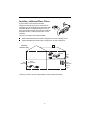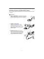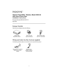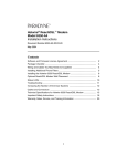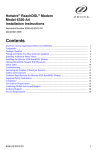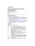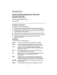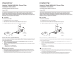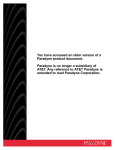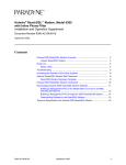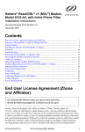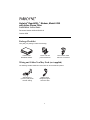
1
Hotwire® ReachDSL™ Modem, Model 6390
with Inline Phone Filter
Installation Instructions
Document Number 6390-A2-GN10-10
October 2002
Package Checklist
Verify that your package contains the following:
Rea
chD
SL
PWR
ALM
TST
LINE
TX/R
X
ETH
ERN
ET
Hotwire 6390
ReachDSL Modem
Power cord with
power transformer
DSL interface cable
with RJ11 connectors
Wiring and Cables You May Need (not supplied)
The following standard cables and connectors can be used with this product:
Standard RJ11
(or RJ14) wall jack for
the DSL cabling
Ethernet 8-pin
straight-through or
crossover cable
1
Installing Additional Phone Filters
E
SERV
P
geprufte
Sicherheit
IC
TUY
LR
92
99
7
L. AC
T.E
CE
. EQ
E1 SS
00 UIPMAR
29 Y
6 EN
T
R
PROD
M
ad
e
UCT
in
TM
/N
08
P
ho
ne
Ch
in 02
a
-3
Be / Fa 39
l Fu br
2se iquè 00
In Ch
c.
11 ina
98
Fi
lte
r
LI
N
E
A phone filter is recommended to minimize
background noise during a phone conversation on
telephones not connected directly to the Hotwire 6390
ReachDSL Modem. If additional telephones in your
home or business share the same phone line with the
ReachDSL modem, install one phone filter on each
telephone.
P
H
O
N
E
There are two Hotwire phone filters available:
Hotwire 6035 Universal Phone Filter is designed for use with a tabletop phone.
Hotwire 6040 Wall Jack Phone Filter is designed for use with a wall phone.
Customer
Premises (CP)
ReachDSL
Modem
RJ11
Wall
Jack
POWER
ETHER
NET
PHONE
RJ11
Wall Jack
LINE
6035
Phone Filter
6040
Wall Jack
Phone
Filter
01-16998
Contact your sales or service representative to order Hotwire phone filters.
2
Installing the Hotwire 6390 ReachDSL Modem
Place the Hotwire 6390 ReachDSL Modem on a flat surface with clearance for the rear
connectors.
Procedure
1. UNPLUG TELEPHONE. If a telephone is connected at
RJ11
Wall Jack
the RJ11 wall jack where the ReachDSL modem will be
installed, unplug the telephone line from the wall jack.
2. CONNECT A TELEPHONE.
(Optional – go to Step 3 if you are not
connecting a telephone to the modem.)
PHONE
POWE
R
ETHERN
Plug the existing telephone interface cable
that was unplugged in Step 1 into the jack
labeled PHONE.
PHON
3. CONNECT DSL LINE. Use the supplied
E LIN
E
LINE
RJ11 6-pin interface cable for the ReachDSL
line connection. Insert one end of the cable
into the jack labeled LINE. Insert the other
end of the cable into the RJ11 wall jack.
PHONE
LINE
RJ11
6-pin
Interface
Cable
3
ET
RJ11
Wall
Jack
4. CONNECT TO PC OR ETHERNET HUB. Use an 8-pin Ethernet cable
(straight-through or crossover) for the Ethernet connection. Insert one end of the
cable into the jack labeled ETHERNET.
Connect to one of the following:
—
PC. Use an Ethernet standard,
straight-through cable and connect
the other end to a PC with an
Ethernet Network Interface Card
(NIC) installed.
ETHERNET
POWER
ETHERN
ET
PC with Ethernet
Network Interface
Card
Ethernet
Straight-through
Cable
– or –
—
Ethernet Hub. Use an Ethernet
standard, straight-through cable and
connect the other end to an Ethernet
hub’s Uplink port. (To connect to a
hub’s standard port, use an Ethernet
crossover cable).
ETHERNET
POWER
ETHERN
ET
Ethernet
Hub
1
2
3
4
5
6
7
8
Ethernet
Straight-through
Cable
5. CONNECT TO POWER. Insert the supplied power cord’s
round end into the jack labeled POWER. Plug the
transformer into an AC outlet.
POWER
When the power cord is installed, the ReachDSL modem
goes through a power-on self-test.
The ReachDSL modem hardware installation is now complete.
POWER
Transformer
For More Information
For more information about the Hotwire 6390 ReachDSL Modem, including front panel
LED status, troubleshooting, cabling, command line interface, downloading, and
technical specifications, please refer to the Hotwire ReachDSL Modem, Model 6390 with
Inline Phone Filter, Installation and Operation Supplement, Document
Number 6390-A2-GK40. This document is available online at www.paradyne.com.
Select Library
Technical Manuals
Hotwire DSL Systems.
→
→
4
!
Important Safety Instructions
1. Read and follow all warning notices and instructions marked on the product or included in the manual.
2. Slots and openings in the cabinet are provided for ventilation. To ensure reliable operation of the product
and to protect it from overheating, these slots and openings must not be blocked or covered.
3. Do not allow anything to rest on the power cord and do not locate the product where persons will walk on
the power cord.
4. Do not attempt to service this product yourself, as opening or removing covers may expose you to
dangerous high voltage points or other risks. Refer all servicing to qualified service personnel.
5. General purpose cables are used with this product for connection to the network. Special cables, which may
be required by the regulatory inspection authority for the installation site, are the responsibility of the
customer. Use a UL Listed, CSA certified, minimum No. 24 AWG line cord for connection to the Digital
Subscriber Line (DSL) network.
6. When installed in the final configuration, the product must comply with the applicable Safety Standards and
regulatory requirements of the country in which it is installed. If necessary, consult with the appropriate
regulatory agencies and inspection authorities to ensure compliance.
7. A rare phenomenon can create a voltage potential between the earth grounds of two or more buildings. If
products installed in separate buildings are interconnected, the voltage potential may cause a hazardous
condition. Consult a qualified electrical consultant to determine whether or not this phenomenon exists and,
if necessary, implement corrective action prior to interconnecting the products.
8. Input power to this product must be provided by one of the following: (1) a UL Listed/CSA certified power
source with a Class 2 or Limited Power Source (LPS) output for use in North America, or (2) a certified
transformer, with a Safety Extra Low Voltage (SELV) output having a maximum of 240 VA available, for use
in the country of installation.
9. In addition, since the equipment is to be used with telecommunications circuits, take the following
precautions:
—
Never install telephone wiring during a lightning storm.
—
Never install telephone jacks in wet locations unless the jack is specifically designed for wet locations.
—
Never touch uninsulated telephone wires or terminals unless the telephone line has been
disconnected at the network interface.
—
Use caution when installing or modifying telephone lines.
—
Avoid using a telephone (other than a cordless type) during an electrical storm. There may be a
remote risk of electric shock from lightning.
—
Do not use the telephone to report a gas leak in the vicinity of the leak.
CE Marking
When the product is marked with the CE mark on the equipment label, a supporting Declaration of Conformity
may be downloaded from the Paradyne World Wide Web site at www.paradyne.com. Select Library Technical
CE Declarations of Conformity.
Manuals
→
→
! CANADA – EMI NOTICE:
This Class B digital apparatus meets all requirements of the Canadian interference-causing
equipment regulations.
Cet appareil numérique de la classe B respecte toutes les exigences du règlement sur le matérial
brouilleur du Canada.
5
Japan – Notices
This is a Class B product based on the standard of the Voluntary Control Council for
Interference from Information Technology Equipment (VCCI). If this is used near a radio or
television receiver in a domestic environment, it may cause radio interference. Install and use
the equipment according to the instruction manual.
Declaration of Conformity
This Declaration of Conformity is made by Paradyne Corporation pursuant to Parts 2 and 15 of the Federal
Communications Commission’s Rules. This compliance information statement pertains to the following products:
Trade Name:
Model Number:
Hotwire
6390-Ax-2xx
This device complies with Part 15 of the FCC Rules. Operation is subject to the following two conditions: (1) this
device may not cause harmful interference, and (2) this device must accept any interference received, including
interference that may cause undesired operation.
The name, address, and telephone number of the responsible party is given below:
Paradyne Corporation
8545 126th Avenue North
Largo, FL 33773-1502
Phone: (727) 530-2000
The authority to operate this equipment is conditioned by the requirement that no modifications will be made to
the equipment unless the changes or modifications are expressly approved by Paradyne Corporation.
This equipment has been tested and found to comply with the limits for a Class B digital device, pursuant to Part
15 of the FCC Rules. These limits are designed to provide reasonable protection against harmful interference in a
residential installation. This equipment generates, uses, and can radiate radio frequency energy and, if not
installed and used in accordance with the instructions, may cause harmful interference to radio communications.
However, there is no guarantee that interference will not occur in a particular installation. If this equipment does
cause harmful interference to radio or television reception, which can be determined by turning the equipment off
and on, the user is encouraged to try to correct the interference by one or more of the following measures:
Reorient or relocate the receiving antenna.
Increase the separation between the equipment and receiver.
Connect the equipment into an outlet on a circuit different from that to which the receiver is connected.
Consult the dealer or an experienced radio/TV technician for help.
6
Supplier’s Declaration of Conformity
Place of Issue:
Paradyne Corporation
8545 126th Avenue North
Largo, FL 33773-1502
USA
Date of Issue:
10/17/2002
Paradyne Corporation, located at the above address, hereby certifies that the Hotwire® ReachDSL™ Model
Number 6390-AX-210, bearing labeling identification number US:AW2DL03B6390-AX complies with: the Federal
Communications Commission’s (“FCC”) Rules and Regulations 47 CFR Part 68, the Administrative Council on
Terminal Attachments (“ACTA”)-adopted technical criteria TIA/EIA/IS-968, “Telecommunications – Telephone
Terminal Equipment –Technical Requirements for Connection of Terminal Equipment To the Telephone Network,
July 2001” and TIA/EIA/IS-883, “Telecommunications – Telephone Terminal Equipment – Supplemental Technical
Requirements for Connection of Stutter Dial Tone Detection Devices and ADSL Modems to the Telephone
Network, June 2001.”
Patrick Murphy
Senior Vice President, Chief Financial Officer
Notice to Users of the United States Telephone Network
The following notice applies to versions of the ReachDSL™ Modem, Model 6390 that have been FCC Part 68
approved.
This equipment complies with Part 68 of the FCC rules and the requirements adopted by the Administrative
Council for Terminal Attachment (ACTA). On the bottom side of this equipment is a label that contains, among
other information, a product identifier in the format US:AAAEQ##TXXXX. If requested, this number must be
provided to the Telephone Company.
This equipment is intended to connect to the Public Switched Telephone Network through a Universal Service
Order Code (USOC) type RJ11C or RJ14C jack. A plug and jack used to connect this equipment to the premises
wiring and telephone network must comply with the applicable FCC Part 68 rules and requirements adopted by
the ACTA. A compliant telephone cord and modular plug is provided with this product. It has been designed to be
connected to a compatible modular jack that is also compliant.
The Ringer Equivalence Number (or REN) is used to determine the number of devices that may be connected to
a telephone line. Excessive RENs on a telephone line may result in the devices not ringing in response to an
incoming call. In most but not all areas, the sum of RENs should not exceed five (5.0). To be certain of the
number of devices that may be connected to a line, as determined by the total RENs, contact the local Telephone
Company. The REN for this product is part of the product identifier that has the format US:AAAEQ##TXXXX.
The digits represented by ## are the REN without a decimal point. For example, 03 represents a REN of 0.3.
If the ReachDSL™ Modem causes harm to the telephone network, the Telephone Company will notify you in
advance that temporary discontinuance of service may be required. But if advance notice is not practical, the
Telephone Company will notify the customer as soon as possible. Also, you will be advised of your right to file a
complaint with the FCC if you believe it is necessary.
The Telephone Company may make changes in its facilities, equipment, operations or procedures that could
affect the operation of the equipment. If this happens, the Telephone Company will provide advance notice in
order for you to make necessary modifications to maintain uninterrupted service.
If trouble is experienced with the ReachDSL™ Modem, refer to the repair and warranty information in this
document.
If the equipment is causing harm to the telephone network, the Telephone Company may request that you
disconnect the equipment until the problem is resolved.
The user may make no repairs to the equipment.
Connection to party line service is subject to state tariffs. Contact the state public utility commission, public
service commission or corporation commission for information.
7
If the site has specially wired alarm equipment connected to the telephone line, ensure the installation of the
ReachDSL™ Modem does not disable the alarm equipment. If you have questions about what will disable alarm
equipment, consult your Telephone Company or a qualified installer.
Notice to Users of the Canadian Telephone Network
NOTICE: This equipment meets the applicable Industry Canada Terminal Equipment Technical Specifications.
This is confirmed by the registration number. The abbreviation IC before the registration number signifies that
registration was performed based on a Declaration of Conformity indicating that Industry Canada technical
specifications were met. It does not imply that Industry Canada approved the equipment.
NOTICE: The Ringer Equivalence Number (REN) for this terminal equipment is labeled on the equipment. The
REN assigned to each terminal equipment provides an indication of the maximum number of terminals allowed to
be connected to a telephone interface. The termination on an interface may consist of any combination of devices
subject only to the requirement that the sum of the Ringer Equivalence Numbers of all the devices does not
exceed five.
If your equipment is in need of repair, refer to Warranty, Sales, Service, and Training Information.
Warranty, Sales, Service, and Training Information
Contact your local sales representative, service representative, or distributor directly for any help needed. For
additional information concerning warranty, sales, service, repair, installation, documentation, training, distributor
locations, or Paradyne worldwide office locations, use one of the following methods:
Internet: Visit the Paradyne World Wide Web site at www.paradyne.com. (Be sure to register your
warranty at www.paradyne.com/warranty.)
Telephone: Call our automated system to receive current information by fax or to speak with a company
representative.
—
Within the U.S.A., call 1-800-870-2221
—
Outside the U.S.A., call 1-727-530-2340
Trademarks
Hotwire is a registered trademark of Paradyne Corporation. ReachDSL is a trademark of Paradyne Corporation.
All other products and services mentioned herein are the trademarks, service marks, registered trademarks, or
registered service marks of their respective owners.
*6390-A2-GN10-10*
*6390-A2-GN10-10*
Copyright © 2002 Paradyne Corporation. Printed in U.S.A.
8