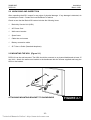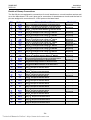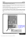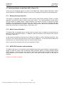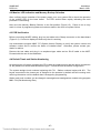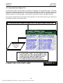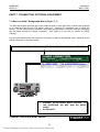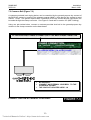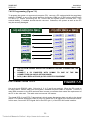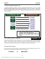
1
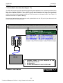
SAMSUNG
DCS-816
INSTALLATION
MANUAL
Technical Manuals Online! - http://www.tech-man.com
SAMSUNG ELECTRONICS CO. LTD.
Publication Information
Samsung Electronics reserves the right without prior notice to revise information in this publication for any
reason.
Samsung Electronics also reserves the right without prior notice to make changes in design or components
of equipment as engineering and manufacturing may warrant.
Copyright 1999
Samsung Electronics Co. Ltd
All rights reserved. No part of this manual may be reproduced in any form or by any means - graphic,
electronic or mechanical, including recording, taping, photocopying or information retrieval systems without express written permission of the publisher of this material.
March/99
Technical Manuals Online! - http://www.tech-man.com
SAMSUNG
DCS-816
Installation
March 1999
Table of Contents
PART 1. SITE REQUIREMENTS..................................................................................... 1-1
PART 2. INSTALLING THE BASIC KSU …
…
…
…
…
…
…
…
…
…
…
…
…
…
…
…
…
…
…
…2-1
2.1
2.2
2.3
2.4
2.5
2.6
2.7
System Configuration and Capacity ..................................................................................................... 2-1
Unpacking and Inspection .................................................................................................................... 2-2
Mounting the KSU (Figure 2-1) ............................................................................................................ 2-2
Grounding the KSU (Figure 2-2) .......................................................................................................... 2-3
MDF Cabling (Figure 2-3)..................................................................................................................... 2-3
External Battery Connection (Figure 2-4)............................................................................................. 2-6
Selecting Options on the Basic KSU (Figure 2-5) ................................................................................ 2-7
PART 3. INSTALLING OPTION CARDS AND TRUNK CARDS (FIGURE 3-1) .............. 3-1
3.1
3.2
3.3
3.4
3.5
SIO1 Option Card (Figure 3-2) ............................................................................................................. 3-2
AA Option Card (Figure 3-2) ................................................................................................................ 3-2
8TRK Card (Figure 3-3)........................................................................................................................ 3-3
2/4BRI Card (Figure 3-3)...................................................................................................................... 3-3
4TRK Card (Figure 3-4)........................................................................................................................ 3-4
PART 4. POWER-UP PROCEDURE …
…
…
…
…
…
…
…
…
…
…
…
…
…
…
…
…
…
…
…
…
..4-1
4.1
4.2
4.3
4.4
Connect Power to the System (Figure 4-1, 4-2)................................................................................... 4-1
Monitor LED Indication and Memory Backup Selection ....................................................................... 4-3
PCB Verification ................................................................................................................................... 4-3
Default Trunk and Station Numbering.................................................................................................. 4-3
PART 5. CONNECTING PSTN CIRCUITS .…
…
…
…
…
…
…
…
…
…
…
…
…
…
…
…
…
…
…
.5-1
5.1
5.2
5.3
5.4
Safety Precautions ............................................................................................................................... 5-1
Loop-Start Lines (Figure 5-1) ............................................................................................................... 5-2
Off Premise Extension (OPX) (Figure 5-2) .......................................................................................... 5-3
ISDN BRI Lines (Figure 5-3) ................................................................................................................ 5-4
PART 6. CONNECTING STATION EQUIPMENT
6.1
6.2
6.3
6.4
6.5
6.6
…
…
…
…
…
…
…
…
…
…
…
…
…
…
…
...6-1
Safety Precautions ............................................................................................................................... 6-1
Digital Keysets (Figure 6-1) .................................................................................................................. 6-2
Single Line Telephones (Figure 6-2) .................................................................................................... 6-3
Door Phone and Door Lock Release (Figure 6-3)................................................................................ 6-4
CTM - CTI Module (TAPI) (Figure 6-4) ................................................................................................ 6-5
ISDN TE (ISDN Phone, G4 FAX, etc) (Figure 6-5) .............................................................................. 6-6
PART 7. CONNECTING OPTIONAL EQUIPMENT …
…
…
…
…
…
…
…
…
…
…
…
…
…
…
.7-1
7.1 Music-on-Hold/ Background Music (Figure 7-1)................................................................................... 7-1
7.2 External Paging (Figure 7-2) ................................................................................................................ 7-2
7.3 Common Bell (Figure 7-3).................................................................................................................... 7-3
7.4 Ring Over Page.................................................................................................................................... 7-4
7.5 Station Message Detail Recording (SMDR) (Figure 7-4) ..................................................................... 7-4
7.6 PC Programming (Figure 7-5).............................................................................................................. 7-5
7.7 Remote Programming (Figure 7-6) ...................................................................................................... 7-6
7.8 Power Failure Transfer......................................................................................................................... 7-6
7.9 Voice Mail/ Auto Attendant (Figure 7-7) ............................................................................................... 7-7
7.10 Information on DCS-816 Serial Interface (Figure 7-8) ....................................................................... 7-8
i
Technical Manuals Online! - http://www.tech-man.com
SAMSUNG
DCS-816
Installation
March 1999
PART 8. CHANGING SOFTWARE (FIGURE 8-1)…
…
…
…
…
…
…
…
…
…
…
…
…
…
…
…
8-1
FIGURES
FIGURE 2-1
FIGURE 2-2
FIGURE 2-3
FIGURE 2-4
FIGURE 2-5
ATTACHING MOUNTING BRACKET TO BACKBOARD
GROUNDING THE KSU
MDF CABLING
CONNECTING A SYSTEM BACKUP BATTERY
SELECTING OPTIONS ON THE BASIC KSU
FIGURE 3-1
FIGURE 3-2
FIGURE 3-3
FIGURE 3-4
INSTALLING OPTION CARDS AND A TRUNK CARD
SIO OPTION CARD AND AA OPTION CARD
8TRK CARD AND 2/4BRI CARD
4TRK CARD
FIGURE 4-1
FIGURE 4-2
CONNECTING POWER TO THE SYSTEM
REPLACING FUSES (POWER SUPPLY UNIT)
FIGURE 5-1
FIGURE 5-2
FIGURE 5-3
CONNECTING LOOP-START LINES
CONNECTING OPX LINES
CONNECTING BRI LINES
FIGURE 6-1
FIGURE 6-2
FIGURE 6-3
FIGURE 6-4
FIGURE 6-5
CONNECTING DIGITAL KEYSETS
CONNECTING SINGLE LINE TELEPHONES
CONNECTING A DOOR PHONE AND LOCK RELEASE
CONNECTING A CTM (TAPI)
CONNECTING ISDN TE
FIGURE 7-1
FIGURE 7-2
FIGURE 7-3
FIGURE 7-4
FIGURE 7-5
FIGURE 7-6
FIGURE 7-7
FIGURE 7-8
CONNECTING EXTERNAL MUSIC
CONNECTING EXTERNAL PAGING EQUIPMENT
CONNECTING AN EXTERNAL LOUD BELL
PIN CONNECTIONS TO PRINTER
PIN CONNECTIONS TO PC
PIN CONNECTIONS TO MODEM
CONNECTING VM/AA
INFORMATION ON SERIAL INTERFACE
FIGURE 8-1
CHANGING SOFTWARE
ii
Technical Manuals Online! - http://www.tech-man.com
SAMSUNG
DCS-816
Installation
March 1999
PART 1. SITE REQUIREMENTS
To install the DCS-816 system, choose a site that meets the following requirements.
ü
Select a location for the Key Service Unit (KSU) that has enough space for easy installation
and adequate lighting. (KSU dimensions [mm]: 465 (H) x 315 (W) x 120 (D))
ü
Select a location that minimises cable lengths. See the Cable Requirements table below.
ü
The equipment should not be exposed to direct sunlight, corrosive fumes, dust, constant
vibration or strong magnetic fields such as those generated by motors and copy machines.
ü
A direct commercial AC power outlet is required. Do not use extension cords. Preferably, a
dedicated circuit should be used to minimise the risk of other electrical equipment being
connected that could adversely affect system operation.
ü
Ensure that all wires and cables going to and coming from the KSU are properly routed. Do
not cross fluorescent lights or run parallel with AC wires.
ü
The equipment must be located in an environment that will maintain a temperature range of
32°F ~ 104°F (0°C ~ 40°C) and a humidity range of 10% ~ 90% non-condensing.
ü
Allow at least 150 mm clearance on both sides and 150 mm clearance on top of the KSU to
ensure proper ventilation.
ü
Do not install within a 2-mile radius of broadcasting antenna or in close proximity to a fire
sprinkler head or other sources of water.
Meeting these requirements will help to ensure proper performance and greater life expectancy of
the system.
CABLE REQUIREMENTS
EQUIPMENT
DIGITAL KEYSETS
SINGLE-LINE STATION
DOOR PHONE
CTI INTERFACE MODULE
CABLE
1 PR. TWISTED
1 PR. TWISTED
2 PR. TWISTED
1 PR. TWISTED
Gauge
0.5mm
0.5mm
0.5mm
0.5mm
MAX FEET
1300
3000
330*
1300
* This is the maximum distance a door phone can be from the DPIM.
maximum of 250 cable metres from the KSU
1-1
Technical Manuals Online! - http://www.tech-man.com
MAX METRES
400
1 KM
100
400
The DPIM can be a
SAMSUNG
DCS-816
Installation
March 1999
NOTICE
Only qualified engineers or technicians can have access to the inside of the
system. In most countries, it is prohibited by law that non-qualified people
install or maintain systems.
1-2
Technical Manuals Online! - http://www.tech-man.com
SAMSUNG
DCS-816
Installation
March 1999
PART 2. INSTALLING THE BASIC KSU
2.1 SYSTEM CONFIGURATION AND CAPACITY
The DCS-816 system consists of the Basic Key Service Unit (KSU), option cards, trunk interface
cards, interface modules and digital keysets. The KSU is a single metal cabinet, and in its basic
form has 16 station ports: twelve (12) keyset ports and four (4) SLT (single line telephone) ports.
Additionally, the KSU contains one (1) trunk expansion slot, two (2) option connectors and
miscellaneous circuits: one (1) external page interface, one (1) general-purpose dry contact and
one (1) music interface selectable to internal built-in music (a melody chip) or external music.
Two types of telephones can be connected to the system: proprietary digital stations called
"keysets" that connect to Digital Line Interface (DLI) ports and standard telephone sets, generally
called "single line telephones", that connect to Single Line Interface (SLI) ports.
The Trunk Expansion slot provides an option to select an analogue trunk card or a basic rate
interface (BRI) card.
The DCS-816 system also has some option cards to provide serial I/O ports or AA facilities.
The KSU starts with two (2) analogue trunk ports and 16 stations, and the trunk expansion slot
provides a maximum capacity of 10 trunk ports (analogue or digital) and 16 stations.
The system maximum capacity is as follows:
Stations
ISDN channels
Analogue C.O. lines
16 (12 keysets, 4 SLTs)
8 (4 BRI ports)
10
Music channel
External page
General-purpose Dry Contact
1 (Internal or External)
1
1
Serial I/O ports
Auto Attendant channels
2 (DB9 connectors)
4
CONFIGURATION NOTES
1.
2.
3.
4.
No KDbs (keyset daughter-boards for additional DLI or SLI expansion) can be installed.
Only one (1) trunk expansion card can be installed.
Only one SIO option card and one AA option card can be installed.
The system cannot accommodate any cards from other Samsung Digital Systems except
for DCS Compact BRI cards.
5. Every analogue trunk interface contains an interface for MPD or PRS which is optional.
The MPD or PRS hybrid chips of the DCS system can be used.
2-1
Technical Manuals Online! - http://www.tech-man.com
SAMSUNG
DCS-816
Installation
March 1999
2.2 UNPACKING AND INSPECTION
After unpacking the KSU, inspect for any signs of physical damage. If any damage is detected, do
not attempt to install. Contact the local distributor for advice.
Check to see that the Basic KSU carton includes the following items.
ü
Basic Key Service Unit (KSU)
ü
AC Power Cord
ü
Wall-mount bracket
ü
Spare fuses
ü
Cable ties and screws
ü
Battery connection cable
ü
SLT User’s Guide (Standard telephone)
2.3 MOUNTING THE KSU (Figure 2-1)
DCS-816 can be wall-mounted. The KSU should be mounted on a plywood backboard at least 15
mm thick. Attach the wall-mount bracket to the backboard with the screws supplied and hang the
KSU on the bracket.
ATTACHING MOUNTING BRACKET TO BACKBOARD
2-2
Technical Manuals Online! - http://www.tech-man.com
FIGURE 2-1
SAMSUNG
DCS-816
Installation
March 1999
2.4 GROUNDING THE KSU (Figure 2-2)
DCS-816 comes equipped ready to use with the third wire AC ground provided through the power
cord. This ground will be adequate for most applications. However, if it is suspected that there is
a problem with the ground provided at the AC outlet, or local codes require a solid earth ground to
be connected to the KSU, the existing third wire ground must be disconnected before power is
applied. The grounding lug on the KSU must be connected to a ground rod or metal cold water
pipe using #10 AWG (approximately 2.6 mm in diameter) solid copper wire. (See Figure 2-2.)
Failure to provide an adequate ground may cause unpredictable operation or even circuit failure.
Warning
Unplug the power cord from the AC outlet before attempting to connect the ground.
Hazardous voltage may cause death or injury. Observe extreme caution when working
with AC power.
GROUNDING THE KSU
FIGURE 2-2
2.5 MDF CABLING (Figure 2-3)
All connections to the DCS-816 system are made via a customer–provided main distribution frame
(MDF) and the cables can be routed into the KSU cabinet from below.
A 25-pair male champ connector and a 4-pair modular jack (RJ-45) on the base board are
prepared for external connections. The connections for SLTs are made through the RJ-45
modular jack and other connections are made through the champ connector. The detailed pin
assignments are as follows. (Note that the colour of wires may be differently specified in some
countries.)
2-3
Technical Manuals Online! - http://www.tech-man.com
SAMSUNG
DCS-816
Installation
March 1999
Details of Champ Connections
The first 20 pins are assigned to connections for trunk interfaces on a trunk interface card as well
as on the base board. The next 6 pins are for connection of miscellaneous circuits and the last 24
pins are assigned to connections for 12 DLI ports on the base board.
Pin
26
1
27
2
28
3
29
4
30
5
31
6
32
7
33
8
34
9
35
10
36
11
37
12
38
13
39
14
40
15
41
16
42
17
43
18
44
19
45
20
46
21
47
22
48
23
49
24
50
25
Colour
W-BL
BL-W
W-O
O-W
W-GR
GR-W
W-BR
BR-W
W-S
S-W
R-BL
BL-R
R-O
O-R
R-GR
GR-R
R-BR
BR-R
R-S
S-R
BK-BL
BL-BK
BK-O
O-BK
BK-GR
GR-BK
BK-BR
BR-BK
BK-S
S-BK
Y-BL
BL-Y
Y-O
O-Y
Y-GR
GR-Y
Y-BR
BR-Y
Y-S
S-Y
VL-BL
BL-VL
VL-O
O-VL
VL-GR
GR-VL
VL-BR
BR-VL
VL-S
S-VL
Circuits/ Functions
st
Tip, 1 Loop-start Trunk Interface on the base board
st
Ring, 1 Loop-start Trunk Interface on the base board
nd
Tip, 2 Loop-start Trunk Interface on the base board
nd
Ring, 2 Loop-start Trunk Interface on the base board
rd
st
Tip of 3 Analogue Trunk or Tip of 1 BRI TX
rd
st
Ring of 3 Analogue Trunk or Ring of 1 BRI TX
th
st
Tip of 4 Analogue Trunk or Tip of 1 BRI RX
th
st
Ring of 4 Analogue Trunk or Ring of 1 BRI RX
th
nd
Tip of 5 Analogue Trunk or Tip of 2 BRI TX
th
nd
Ring of 5 Analogue Trunk or Ring of 2 BRI TX
th
nd
Tip of 6 Analogue Trunk or Tip of 2 BRI RX
th
nd
Ring of 6 Analogue Trunk or Ring of 2 BRI RX
th
rd
Tip of 7 Analogue Trunk or Tip of 3 BRI TX
th
rd
Ring of 7 Analogue Trunk or Ring of 3 BRI TX
th
rd
Tip of 8 Analogue Trunk or Tip of 3 BRI RX
th
rd
Ring of 8 Analogue Trunk or Ring of 3 BRI RX
th
th
Tip of 9 Analogue Trunk or Tip of 4 BRI TX
th
th
Ring of 9 Analogue Trunk or Ring of 4 BRI TX
th
th
Tip of 10 Analogue Trunk or Tip of 4 BRI RX
th
th
Ring of 10 Analogue Trunk or Ring of 4 BRI RX
Tip, General-purpose Dry Contact on the base board
Ring, General-purpose Dry Contact on the base board
Tip, External Page Interface on the base board
Ring, External Page Interface on the base board
Tip, External Music Interface on the base board
Ring, External Music Interface on the base board
st
Tip, 1 DLI port on the base board
st
Ring, 1 DLI port on the base board
nd
Tip, 2 DLI port on the base board
nd
Ring, 2 DLI port on the base board
rd
Tip, 3 DLI port on the base board
rd
Ring, 3 DLI port on the base board
th
Tip, 4 DLI port on the base board
th
Ring, 4 DLI port on the base board
th
Tip, 5 DLI port on the base board
th
Ring, 5 DLI port on the base board
th
Tip, 6 DLI port on the base board
th
Ring, 6 DLI port on the base board
th
Tip, 7 DLI port on the base board
th
Ring, 7 DLI port on the base board
th
Tip, 8 DLI port on the base board
th
Ring, 8 DLI port on the base board
th
Tip, 9 DLI port on the base board
th
Ring, 9 DLI port on the base board
th
Tip, 10 DLI port on the base board
th
Ring, 10 DLI port on the base board
th
Tip, 11 DLI port on the base board
th
Ring, 11 DLI port on the base board
th
Tip, 12 DLI port on the base board
th
Ring, 12 DLI port on the base board
2-4
Technical Manuals Online! - http://www.tech-man.com
Remark
No polarity
No polarity
Expansion card
No polarity
Expansion card
No polarity
Expansion card
No polarity
Expansion card
No polarity
Expansion card
No polarity
Expansion card
No polarity
Expansion card
No polarity
Expansion card
No polarity
No polarity
No polarity
No polarity
No polarity
No polarity
No polarity
No polarity
No polarity
No polarity
No polarity
No polarity
No polarity
No polarity
No polarity
No polarity
SAMSUNG
DCS-816
Installation
March 1999
Details of RJ-45 Connections
Eight pins of the RJ-45 connector are assigned to connections of SLT interface ports on the base
board.
Pin No.
1
8
2
7
3
6
4
5
Circuits/ Functions
st
Tip, 1 SLT port (STN 13) on the base board
Ring, 1st SLT port (STN 13) on the base board
Tip, 2nd SLT port (STN 14) on the base board
Ring, 2nd SLT port (STN 14) on the base board
Tip, 3rd SLT port (STN 15) on the base board
Ring, 3rd SLT port (STN 15) on the base board
Tip, 4th SLT port (STN 16) on the base board
Ring, 4th SLT port (STN 16) on the base board
Remarks
OPX Circuit
No polarity
OPX Circuit
No polarity
No polarity
No polarity
BOTTOM
VIEW
FRONT VIEW
AFTER REMOVING
THE FRONT COVER
FROM
50-PIN CHAMP
CONNECTOR
FROM
8-PIN RJ-45
MDF CABLING
FIGURE 2-3
2-5
Technical Manuals Online! - http://www.tech-man.com
SAMSUNG
DCS-816
Installation
March 1999
2.6 External Battery Connection (Figure 2-4)
It is recommended that an external battery should be installed to backup the system in case of AC
power failure. The DCS-816 system is equipped with battery charging and discharging circuits to
interface with an external battery.
To decide the capacity of the battery, keep in mind that it may damage the system if too large
while it cannot backup the system long enough if too small. The capacity should be not less than
6AH nor more than 26AH. The battery voltage should be 48 volts.
To connect an external battery, first pick out the battery connection cable through the MDF cable
path. Connect the RED lead of the cable to the positive (+) terminal of the battery and the BLACK
lead to the negative (-) terminal. Then insert the housing connector into the header in the power
supply.
NOTE: The actual connection should be done as the final step in the installation of the KSU.
ü
CONNECTING A SYSTEM BACKUP BATTERY
2-6
Technical Manuals Online! - http://www.tech-man.com
USE EXTREME CAUTION
ON THE POLARITY AND
THE INRUSH CURRENT
AT
THE
POINT
OF
CONNECTION
FIGURE 2-4
SAMSUNG
DCS-816
Installation
March 1999
2.7 Selecting Options on the Basic KSU (Figure 2-5)
There are some hardware options to select in the Basic KSU: Memory Backup Selection, Music
Source Selection and MPD/PRS selection for the two (2) analogue trunk lines on the base board.
2.7.1 Memory Backup Selection
The system is equipped with 256Kbyte of data memory and memory backup circuitry (a super
capacitor) to protect the data in case of any power failure. The memory backup circuitry has a
shunt-pin switch to enable backup. Before shipment, the switch is set OFF to prevent the super
capacitor from discharging during shipment and storage, and it should be switched ON after
installing and programming the system. Otherwise, the customer data and the programmed data
will be lost in the event of a power failure. (See Figure 2-5.)
2.7.2 Music Source Selection
The Basic KSU is equipped with a melody chip to provide music to stations and trunk lines as
Music-on-Hold or Background Music. In addition, it has an interface for an external music source,
(CD player, radio etc).
As the system provides only a single music channel for Music-on-Hold or Background Music, refer
to Figure 2-5 to select the music source at the end of installation. A shunt-pin switch selects the
music source: the internal melody chip or an external music source.
How to connect the external music source is explained in Part 7.
2.7.3 MPD/ PRS Selection and Installation
The Basic KSU has two (2) analogue trunk interfaces and each trunk interface is equipped with a
socket to install an option chip for Metering Pulse Detection (MPD) or Polarity Reverse Signal
(PRS) detection. (See Figure 2-5 for position of option chip sockets and ensure that the chips are
firmly inserted into the sockets.) One chip per line. DCS option chips for MPD or PRS can be
installed.
Contact your dealer for details.
2-7
Technical Manuals Online! - http://www.tech-man.com
SAMSUNG
DCS-816
Installation
March 1999
MPD/PRS
SOCKET
FOR TRK1
MPD/PRS
SOCKET
FOR TRK2
MUSIC
SOURCE
EXT
INT
MEMORY
BACKUP
ON
OFF
SELECTING OPTIONS ON THE BASIC KSU
2-8
Technical Manuals Online! - http://www.tech-man.com
FIGURE 2-5
SAMSUNG
DCS-816
Installation
March 1999
PART 3. INSTALLING OPTION CARDS AND TRUNK CARDS (Figure 3-1)
Unpack and inspect each card before installing. Check for signs of physical damage. If any
damage is detected, do not attempt to install. Contact the local distributor for advice immediately.
The DCS-816 system has one (1) trunk expansion slot for a trunk card and two (2) option
connections for SIO and AA. See Figure 3-1.
INSTALLING OPTION CARDS AND A TRUNK CARD
3-1
Technical Manuals Online! - http://www.tech-man.com
FIGURE 3-1
SAMSUNG
DCS-816
Installation
March 1999
3.1 SIO1 Option Card (Figure 3-2)
Two (2) serial interfaces with DB9 connectors
There are no hardware options to select on this card. Only one card can be installed at the
dedicated location. Ensure that it is fully inserted into two (2) card connectors.
3.2 AA Option Card (Figure 3-2)
Four (4) channel built-in Auto Attendant
There is a memory backup selection switch (a shunt pin) which should be set ON after installation.
Only one card can be installed at the dedicated location. Ensure that it is fully inserted into two (2)
card connectors.
AA
SIO1
TWO
DB9
CONNECTORS
CARD
CONNECTORS
AA MEMORY
BACKUP
CARD
CONNECTORS
ON - UPPER
SIO1 OPTION CARD AND AA OPTION CARD
3-2
Technical Manuals Online! - http://www.tech-man.com
FIGURE 3-2
SAMSUNG
DCS-816
Installation
March 1999
3.3 8TRK Card (Figure 3-3)
Eight (8) analogue trunk interfaces with MPD or PRS option
The card has eight (8) interfaces for MPD or PRS optional chips. Install any MPD or PRS chip
before installing the card. Only one card can be installed in the expansion slot. Ensure that it is
fully inserted into the slot.
3.4 2/4BRI Card (Figure 3-3)
Two (2) or four (4) ISDN BRI ports
There are no hardware options to select on this card. This card supports both S and T reference
points defined by ITU-T. You can select the S/T mode of each port respectively by programming
(MMC). Note that the card does not provide power to ISDN terminal equipment even though you
select So mode.
Insert the card and ensure that it is pushed firmly into the slot.
2 CAPACITORS
PER LINE
MPD/PRS SOCKETS FOR
TRK1 TO TRK8 FROM THE TOP
FIGURE 3-3
8TRK CARD AND 2/4BRI CARD
3-3
Technical Manuals Online! - http://www.tech-man.com
SAMSUNG
DCS-816
Installation
March 1999
3.5 4TRK Card (Figure 3-4)
Four (4) analogue trunk interfaces with MPD or PRS options
The card has four (4) interfaces for MPD or PRS option chips. Install any MPD or PRS chip before
installing the card. For PRS and 50Hz MPD facilities, the capacitors marked on Figure 3-4 should
be replaced with wire-jumpers. Install the card and ensure that it is fully inserted into the slot.
Some components are not mounted. Only one card per system.
2 CAPACITORS
PER PORT
MPD/PRS SOCKETS
FOR TRK1 TO TRK4
FROM THE TOP
FIGURE 3-4
4TRK CARD
3-4
Technical Manuals Online! - http://www.tech-man.com
SAMSUNG
DCS-816
Installation
March 1999
PART 4. POWER-UP PROCEDURE
4.1 Connect Power to the System (Figures 4-1 and 4-2)
It is recommended that you verify system operation and then make the external connections. The
procedures are as follows:
Ø
Remove any cables for external connections from the system if you have already plugged any
cables in.
Ø
Verify the AC voltage at the dedicated AC outlet. The voltage should always be between
176 ACVrms and 264 ACVrms, at a frequency between 48 Hz and 63Hz.
Ø
Make sure that the AC power switch is in the OFF position (Figure 4-1) and that the Memory
Backup switch is OFF (Figure 2-5).
Ø
Ensure that any option cards and the trunk expansion card (if installed) are firmly inserted.
Ø
Plug the system power cord into the dedicated AC outlet.
Ø
Turn the AC power switch ON.
Ø
Check that the AC LED and the DC LED next to the AC power switch (Figure 4-1) light steady.
Otherwise, check the fuses in the power supply unit as follows:
²
Turn the AC power switch OFF
²
Remove the front cover and the power supply unit cover
²
Check the AC fuses (Figure 4-2). Replace them with spare fuses if they are blown out.
Otherwise, contact your distributor or dealer for advice.
²
Remove the option cards and the trunk expansion card (if installed).
²
Turn the AC power switch ON and check the LED operation again. If the problem is
corrected, you have to replace the option cards or the trunk expansion card with new
cards because at least one of them must be defective. Otherwise, contact your distributor
or dealer for advice.
4-1
Technical Manuals Online! - http://www.tech-man.com
SAMSUNG
DCS-816
Installation
March 1999
LEDs
CONNECTING POWER TO THE SYSTEM
AC Power
Switch
FIGURE 4-1
EXTERNAL
BATTERY
FUSES
AC FUSES
REPLACING FUSES (POWER SUPPLY UNIT)
4-2
Technical Manuals Online! - http://www.tech-man.com
FIGURE 4-2
SAMSUNG
DCS-816
Installation
March 1999
4.2 Monitor LED Indication and Memory Backup Selection
After verifying proper operation of the power supply, turn your system ON to check the operation
of the monitor LED on the base board. The LED should flicker rapidly indicating the main
processor is functioning.
Now move the Memory Backup Selector to the ON position (Figure 2-5). Failure to do so may
result in a loss of programming data and customer data in the event of a power failure.
4.3 PCB Verification
Before connecting all MDF cabling, plug in a test cable to the Champ connector on the base board
(Figure 2-3). Connect a display set and verify that it is working.
Use maintenance program MMC 727 (System Version Display) to verify the system version and
software version and to confirm the status of installed cards. Otherwise, please contact your
dealer for advice.
Remove the test cable and plug in an amphenol-type cable and an RJ-45 cable to the MDF.
Proceed with the rest of the installation.
4.4 Default Trunk and Station Numbering
At the beginning of system operation the CPU reads the expansion slot and the option connections
for the presence of a card and identifies the type. It stores this as the default configuration.
The system assigns trunk numbers beginning with 701. Station numbers begins with 201. The
keyset connected to the lowest port is assigned to the operator by default and all incoming trunk
calls ring the station until the default data is changed by programming.
Station and trunk numbers can be changed, rearranged and reassigned as needed using program
MMC 724 (Dial Numbering Plan).
4-3
Technical Manuals Online! - http://www.tech-man.com
SAMSUNG
DCS-816
Installation
March 1999
This page is intentionally left blank.
4-4
Technical Manuals Online! - http://www.tech-man.com
SAMSUNG
DCS-816
Installation
March 1999
PART 5. CONNECTING PSTN CIRCUITS
5.1 Safety Precautions
To prevent risk of personal injury, follow these precautions at all times when connecting PSTN
circuits.
ü
The Protective Earth (PE) should be firmly connected to the system at all times.
ü
Never install telephone wiring during periods when lightning may occur.
ü
Never install telephone jacks in a wet location unless the jack is specially designed for wet
locations. Use extreme caution.
ü
Never touch non-insulated telephone wires or terminals unless the telephone line has been
disconnected at the network interface.
ü
Use extreme caution when installing or modifying telephone lines.
5-1
Technical Manuals Online! - http://www.tech-man.com
SAMSUNG
DCS-816
Installation
March 1999
5.2 Loop-start Lines (Figure 5-1)
The DCS-816 system requires MDF connection for analogue trunk (loop-start) lines. The Basic
KSU itself is equipped with two analogue trunk lines. Additionally, a 4TRK or an 8TRK card can be
installed in the trunk expansion slot. All connections for loop-start lines can be done through the
champ connector on the base board. See Figure 2-3 and refer to section 2.5 (MDF Cabling).
Use one pair twisted wires and connect each loop-start C.O. line to the trunk port you choose via
the champ connector on the base board.
25 PAIR CABLE WITH FEMALE CONNECTOR TO THE BASE CHAMP CONNECTOR
CHAMP CONNECTION
PSTN (C.O.)
Loop-Start
Lines
²
²
²
PIN COLOUR
CIRCUITS / FUNCTIONS
26/ 1 W-BL/ BL-W
27/ 2 W-O/ O-W
T/R, 1st Trunk on base board
T/R, 2nd Trunk on base board
28/ 3 W-GR/ GR-W
29/ 4 W-BR/ BR-W
30/ 5 W-S/ S-W
31/ 6 R-BL/ BL-R
32/ 7 R-O/ O-R
33/ 8 R-GR/ GR-R
34/ 9 R-BR/ BR-R
35/10 R-S/ S-R
T/R, 1st Trunk on 4/8TRK
T/R, 2nd Trunk on 4/8TRK
T/R, 3rd Trunk on 4/8TRK
T/R, 4th Trunk on 4/8TRK
T/R, 5th Trunk on 8TRK
T/R, 6th Trunk on 8TRK
T/R, 7th Trunk on 8TRK
T/R, 8th Trunk on 8TRK
NO POLARITY
2 LOOP-START LINES TO THE BASIC KSU.
THESE LINES WILL BE TRANSFERRED TO STN
15 AND STN 16 IN CASE OF POWER FAILURE
4 OR 8 ADDITIONAL LOOP-START LINES
IF A 4TRK OR AN 8TRK CARD IS INSTALLED
CONNECTING LOOP-START LINES
5-2
Technical Manuals Online! - http://www.tech-man.com
FIGURE 5-1
SAMSUNG
DCS-816
Installation
March 1999
5.3 Off Premise Extension (OPX) (Figure 5-2)
The Basic KSU is equipped with four (4) SLI interfaces and only the first two (2) SLI interfaces are
specially designed for Long Line or Off Premise Extension (OPX) connections. The interfaces
have the same over-voltage and over-current protection circuits as an analogue trunk interface.
All connections for OPX lines can be done through the RJ-45 connector on the base board. See
Figure 2-3 and refer to the section 2.5 (MDF Cabling).
Use one pair twisted wires and connect each OPX line to the SLI port of your choice via the RJ-45
connector on the base board.
4 PAIR CABLE WITH MALE CONNECTOR TO THE BASE RJ-45 CONNECTOR
RJ-45 CONNECTION
PIN COLOUR
CIRCUITS / FUNCTIONS
1/ 8 W-BL/ BL-W
2/ 7 W-O/ O-W
T/R, 1st SLI on base board
T/R, 2nd SLI on base board
Long Line
Extension
²
²
²
NO POLARITY
A LOOP-DISCONNECT FACILITY PER LINE
CONNECT TO ONE OF THE 1ST OR THE 2ND SLI
CIRCUITS ON THE BASE BOARD VIA THE RJ-45
CONNECTOR.
CONNECTING OPX LINES
FIGURE 5-2
5-3
Technical Manuals Online! - http://www.tech-man.com
SAMSUNG
DCS-816
Installation
March 1999
5.4 ISDN BRI Lines (Figure 5-3)
The DCS-816 system requires MDF connection for ISDN BRI (Basic Rate Interface) lines. The
system has a trunk expansion slot where a 4BRI card or a 2BRI card can be installed. All
connections for ISDN BRI lines can be done through the champ connector on the base board.
See Figure 2-3 and refer to section 2.5 (MDF Cabling).
Use two pair twisted wires and connect each BRI line to the trunk port of your choice via the
champ connector on the base board.
25 PAIR CABLE WITH FEMALE CONNECTOR TO THE BASE CHAMP CONNECTOR
IN A NOISY ENVIRONMENT
USE INSULATED CABLE
ISDN
BRI
Lines
²
²
CHAMP CONNECTION
PIN COLOUR
CIRCUITS / FUNCTIONS
28/ 3 W-GR/ GR-W
29/ 4 W-BR/ BR-W
30/ 5 W-S/ S-W
31/ 6 R-BL/ BL-R
32/ 7 R-O/ O-R
33/ 8 R-GR/ GR-R
34/ 9 R-BR/ BR-R
35/10 R-S/ S-R
T/R, TX of 1 BRI port
T/R, RX of 1st BRI port
T/R, TX of 2nd BRI port
T/R, RX of 2nd BRI port
T/R, TX of 3rd BRI port (4BRI)
T/R, RX of 3rd BRI port (4BRI)
T/R, TX of 4th BRI port (4BRI)
th
T/R, RX of 4 BRI port (4BRI)
st
4 BRI PORTS ON 4BRI CARD
2 BRI PORTS ON 2BRI CARD
2 CHANNELS PER PORT
So / To APPLICATION ON A PORT BASIS
CONNECTING BRI LINES
FIGURE 5-3
5-4
Technical Manuals Online! - http://www.tech-man.com
SAMSUNG
DCS-816
Installation
March 1999
PART 6. CONNECTING STATION EQUIPMENT
6.1 Safety Precautions
To prevent risk of personal injury, follow these precautions at all times when connecting station
equipment.
ü
The Protective Earth (PE) should be firmly connected to the system at all times.
ü
Never install telephone wiring during periods when lightning may occur.
ü
Never install telephone jacks in a wet location unless the jack is specially designed for wet
locations. Use extreme caution.
ü
Never touch non-insulated telephone wires or terminals unless the telephone line has been
disconnected at the network interface.
ü
Use extreme caution when installing or modifying telephone lines.
6-1
Technical Manuals Online! - http://www.tech-man.com
SAMSUNG
DCS-816
Installation
March 1999
6.2 Digital Keysets (Figure 6-1)
A variety of Samsung Digital Keysets can be connected to the DCS-816 system which can
accommodate a maximum of 12 keysets. The system requires MDF connection for digital keysets
and all connections can be done through the champ connector on the base board. See Figure 23 and refer to section 2.5 (MDF Cabling).
Use one pair twisted wires and connect each keyset to the DLI port of your choice via the champ
connector on the base board.
25 PAIR CABLE WITH FEMALE CONNECTOR TO THE BASE CHAMP CONNECTOR
CHAMP CONNECTION
²
²
²
PIN COLOUR
CIRCUITS / FUNCTIONS
39/14 BK-BR/ BR/BK
40/15 BK-S/ S-BK
41/16 Y-BL/ BL-Y
42/17 Y-O/ O-Y
43/18 Y-GR/ GR-Y
44/19 Y-BR/ BR-Y
45/20 Y-S/ S-Y
46/21 VL-BL/BL-VL
47/22 VL-O/ O-VL
48/23 VL-GR/ GR-VL
49/24 VL-BR/ BR-VL
50/25 VL-S/ S-VL
T/R, 1st DLI port on base
T/R, 2nd DLI port on base
T/R, 3rd DLI port on base
T/R, 4th DLI port on base
T/R, 5th DLI port on base
T/R, 6th DLI port on base
T/R, 7th DLI port on base
T/R, 8th DLI port on base
T/R, 9th DLI port on base
T/R, 10th DLI port on base
T/R, 11th DLI port on base
T/R, 12th DLI port on base
NO POLARITY
CONNECT A SAMSUNG DIGITAL KEYSET TO
ANY DLI CIRCUIT ON THE BASIC KSU
NO KDB-DLI OR KDB-SLI CAN BE INSTALLED IN
ANY KEYSET
CONNECTING DIGITAL KEYSETS
FIGURE 6-1
6-2
Technical Manuals Online! - http://www.tech-man.com
SAMSUNG
DCS-816
Installation
March 1999
6.3 Single Line Telephones (Figure 6-2)
The DCS-816 system has four (4) SLT interfaces to which conventional telephones or OPX lines
can be connected. The system requires MDF connection for single line telephones and all
connections can be done through the RJ-45 connector on the base board. See Figure 2-3 and
refer to section 2.5 (MDF Cabling).
Use one pair twisted wires and connect each telephone to the SLI port of your choice via the RJ45 connector on the base board.
4 PAIR CABLE WITH MALE CONNECTOR TO THE BASE RJ-45 CONNECTOR
RJ-45 CONNECTION
PIN COLOUR
CIRCUITS / FUNCTIONS
1/ 8
2/ 7
3/ 6
4/ 5
T/R, 1st SLI on base board
T/R, 2nd SLI on base board
T/R, 3rd SLI on base board
T/R, 4th SLI on base board
W-BL/ BL-W
W-O/ O-W
W-GR/ GR-W
W-BR/ BR-W
NOTE:
UK phones use pin
Connection 2 and 5.
²
²
²
²
NO POLARITY
A LOOP-DISCONNECT FACILITY PER LINE
CONNECT A CONVENTIONAL TELEPHONE TO
ANY SLI CIRCUIT ON THE BASIC KSU
TRK 1 AND TRK 2 WILL BE AUTOMATICALLY
TRANSFERRED TO SLI 3 (STN15) AND SLI 4
(STN16) IN CASE OF POWER FAILURE
CONNECTING SINGLE LINE TELEPHONES
6-3
Technical Manuals Online! - http://www.tech-man.com
FIGURE 6-2
SAMSUNG
DCS-816
Installation
March 1999
6.4 Door Phone and Door Lock Release (Figure 6-3)
The DCS DPIM module is required to install a door phone or a door lock release. The DPIM has a
door phone interface and a door lock release circuit, which can be connected to any DLI port of
DCS-816. The system requires MDF connection for DPIM modules and modular jack connection
for a door phone or a door lock release. DPIM connections can be done through the champ
connector on the base board. See Figure 2-3 and refer to section 2.5 (MDF Cabling).
Use one pair twisted wires, connect each DPIM module to the DLI port of your choice via the
champ connector on the base board and connect a door phone or a door lock release to the
DPIM.
25 PAIR CABLE WITH FEMALE CONNECTOR TO THE BASE CHAMP CONNECTOR
CHAMP CONNECTION
3 4
LOCK
DOOR BOX
PIN COLOUR
CIRCUITS / FUNCTIONS
39/14 BK-BR/ BR/BK
40/15 BK-S/ S-BK
41/16 Y-BL/ BL-Y
42/17 Y-O/ O-Y
43/18 Y-GR/ GR-Y
44/19 Y-BR/ BR-Y
45/20 Y-S/ S-Y
46/21 VL-BL/BL-VL
47/22 VL-O/ O-VL
48/23 VL-GR/ GR-VL
49/24 VL-BR/ BR-VL
50/25 VL-S/ S-VL
T/R, 1st DLI port on base
T/R, 2nd DLI port on base
T/R, 3rd DLI port on base
T/R, 4th DLI port on base
T/R, 5th DLI port on base
T/R, 6th DLI port on base
T/R, 7th DLI port on base
T/R, 8th DLI port on base
T/R, 9th DLI port on base
T/R, 10th DLI port on base
T/R, 11th DLI port on base
T/R, 12th DLI port on base
RED
4
£Ð£«
TWO PAIR
BLACK
£Ð£-
MODU LAR CABLE
GREEN
5
3
YELLOW
2
LINE
THREE PAIR
MODULAR CABLE
²
²
BLUE
WHITE
6
1
TO CUSTOMER-PROVIDED
²
DOOR PHONE
£Ì£±
£Ì£²
CONNECT A DPIM TO ANY DLI PORT AFTER
CONNECTING A DOOR PHONE TO THE DPIM
NO EQUIPMENT CAN BE INSTALLED
OUTDOORS
DOOR LOCK RELEASE RATE : 24VDC, 1A MAX
DOOR LOCK RELEASE
CONNECTING A DOOR PHONE AND LOCK RELEASE
6-4
Technical Manuals Online! - http://www.tech-man.com
FIGURE 6-3
SAMSUNG
DCS-816
Installation
March 1999
6.5 CTM - CTI Module (TAPI) (Figure 6-4)
The DCS CTM module is required to support CTI (TAPI) in the system. The CTM has a DLI
connection and a personal computer (PC) interface, which can be connected to any DLI port of
DCS-816. The system requires MDF connection for CTM modules and modular jack connection
for a keyset. A PC may connect to the module via the DB9 connector. See Figure 2-3 and refer
to section 2.5 (MDF Cabling).
Using one pair twisted wires, connect each CTM module (via the modular jack marked ‘DLI IN’) to
the DLI port of your choice via the champ connector on the base board and then connect the
module (via the other modular jack marked ‘KTS OUT’) to a keyset. A PC can be connected to
the module via the DB9 connector.
A special PC software package is required to run CTI (TAPI) and how to set up the software is
described in the other document in detail. Contact your dealer for information.
25 PAIR CABLE WITH FEMALE CONNECTOR TO THE BASE CHAMP CONNECTOR
CHAMP CONNECTION
3 4
PIN COLOUR
CIRCUITS / FUNCTIONS
39/14 BK-BR/ BR/BK
40/15 BK-S/ S-BK
41/16 Y-BL/ BL-Y
42/17 Y-O/ O-Y
43/18 Y-GR/ GR-Y
44/19 Y-BR/ BR-Y
45/20 Y-S/ S-Y
46/21 VL-BL/BL-VL
47/22 VL-O/ O-VL
48/23 VL-GR/ GR-VL
49/24 VL-BR/ BR-VL
50/25 VL-S/ S-VL
T/R, 1st DLI port on base
T/R, 2nd DLI port on base
T/R, 3rd DLI port on base
T/R, 4th DLI port on base
T/R, 5th DLI port on base
T/R, 6th DLI port on base
T/R, 7th DLI port on base
T/R, 8th DLI port on base
T/R, 9th DLI port on base
T/R, 10th DLI port on base
T/R, 11th DLI port on base
T/R, 12th DLI port on base
P IN
A SS I G N M E N T
¡¡ C T £Í ¡¡
¡¡ ¡¡ ¡¡ ¡¡ ¡¡ £Ð £Ã
COM1
RS-232-C(DB-9)
KTS¡¤ OUT
DLI¡¤ IN
TXD
2
2
RXD
3
3
GND
5
COM2
3 (RxD)
OR
5
9 PIN
²
²
²
2 (TxD)
7 (GND)
25 PIN
CONNECT A CTM TO ANY DLI PORT
YOU CANNOT INSTALL THE EQUIPMENT
OUTDOORS
SPECIAL PC SOFTWARE REQUIRED
CONNECTING A CTM (TAPI)
FIGURE 6-4
6-5
Technical Manuals Online! - http://www.tech-man.com
SAMSUNG
DCS-816
Installation
March 1999
6.6 ISDN TE (ISDN phone, G4 FAX, etc) (Figure 6-5)
ISDN Terminal Equipment can be connected to any circuit on the BRI card if installed. As
described in section 5.4, the system provides So as well as To application on a port basis. The
system requires MDF connection for a BRI card and the connection can be made through the
champ connector. See Figure 2-3 and refer to section 2.5 (MDF Cabling).
Use two pair twisted wires and connect each ISDN TE to the BRI port of your choice via the
champ connector on the base board.
Note that the DCS Compact BRI card does not provide power to the ISDN terminal equipment.
25 PAIR CABLE WITH FEMALE CONNECTOR TO THE BASE CHAMP CONNECTOR
CHAMP CONNECTION
PIN COLOUR
CIRCUITS / FUNCTIONS
28/ 3 W-GR/ GR-W
29/ 4 W-BR/ BR-W
30/ 5 W-S/ S-W
31/ 6 R-BL/ BL-R
32/ 7 R-O/ O-R
33/ 8 R-GR/ GR-R
34/ 9 R-BR/ BR-R
35/10 R-S/ S-R
T/R, TX of 1 BRI port
T/R, RX of 1st BRI port
T/R, TX of 2nd BRI port
T/R, RX of 2nd BRI port
T/R, TX of 3rd BRI port (4BRI)
T/R, RX of 3rd BRI port (4BRI)
T/R, TX of 4th BRI port (4BRI)
T/R, RX of 4th BRI port (4BRI)
st
ISDN TEs
²
²
CONNECT ISDN TE TO ANY BRI PORT WHEN A
BRI CARD IS INSTALLED
NO POWER SUPPLY TO ISDN TE
CONNECTING ISDN TE
FIGURE 6-5
6-6
Technical Manuals Online! - http://www.tech-man.com
SAMSUNG
DCS-816
Installation
March 1999
PART 7. CONNECTING OPTIONAL EQUIPMENT
7.1 Music-on-Hold / Background Music (Figure 7-1)
The DCS-816 system provides one music channel which is from the built-in melody chip (internal)
or an external music source (CD player, radio etc). Section 2.7 describes how to select the
source. For the external music interface, the system requires MDF connection and the connection
can be made through the champ connector. See Figure 2-3 and refer to section 2.5 (MDF
Cabling).
Use one pair twisted wires and connect a CD player or radio to the external music interface via the
champ connector on the base board.
25 PAIR CABLE WITH FEMALE CONNECTOR TO THE BASE CHAMP CONNECTOR
CHAMP CONNECTION
²
²
PIN COLOUR
CIRCUITS/ FUNCTIONS
38/13BK-O/ O-BK
T/R, External Music Interface
CONNECT AN EXTERNAL MUSIC SOURCE TO
THE INTERFACE VIA MDF AND AN AUDIO
CABLE
NO POLARITY
CONNECTING EXTERNAL MUSIC
FIGURE 7-1
7-1
Technical Manuals Online! - http://www.tech-man.com
SAMSUNG
DCS-816
Installation
March 1999
7.2 External Paging (Figure 7-2)
The DCS-816 system is equipped with an interface for external paging. It can be connected to
customer-provided paging equipment. The interface is designed to match 600 Ohm and an
impedance matching transformer may be required if the impedance of the paging equipment is not
600 Ohm. The system requires MDF connection for external paging and the connection can be
made through the champ connector. See Figure 2-3 and refer to section 2.5 (MDF Cabling).
Using one pair twisted wires, connect customer-provided paging equipment to the external paging
interface via the champ connector on the base board.
25 PAIR CABLE WITH FEMALE CONNECTOR TO THE BASE CHAMP CONNECTOR
CHAMP CONNECTION
PIN COLOUR
CIRCUITS/ FUNCTIONS
37/12BK-BL/ BL-BK T/R, External Page Interface
36/11BK-GR/ GR-BK T/R, GP Dry Contact
²
²
²
²
NO POLARITY
CONNECT EXTERNAL PAGING EQUIPMENT TO
THE INTERFACE VIA MDF
DRY CONTACT MAY OPERATE WITH EXTERNAL
PAGING FACILITY AS SHOWN ABOVE
THE CONTACT IS RATED 24VDC- 1A
CONNECTING EXTERNAL PAGING EQUIPMENT
7-2
Technical Manuals Online! - http://www.tech-man.com
FIGURE 7-2
SAMSUNG
DCS-816
Installation
March 1999
7.3 Common Bell (Figure 7-3)
A customer-provided loud ringing device can be controlled by the general-purpose dry contact of
the DCS-816 system by means of the relevant program (MMC). Note that the dry contact is rated
24VDC, 1 Amp. The system requires MDF connection for the dry contact and the connection can
be made through the champ connector. See Figure 2-3 and refer to section 2.5 (MDF Cabling).
Using one pair twisted wires, connect a customer-provided loud bell to the general-purpose dry
contact via the champ connector on the base board.
25 PAIR CABLE WITH FEMALE CONNECTOR TO THE BASE CHAMP CONNECTOR
CHAMP CONNECTION
PIN COLOUR
CIRCUITS/ FUNCTIONS
36/11BK-GR/ GR-BK T/R, GP Dry Contact
²
²
²
NO POLARITY
CONNECT AN EXTERNAL LOUD BELL TO THE
INTERFACE VIA MDF
THE CONTACT IS RATED 24VDC- 1A
CONNECTING AN EXTERNAL LOUD BELL
7-3
Technical Manuals Online! - http://www.tech-man.com
FIGURE 7-3
SAMSUNG
DCS-816
Installation
March 1999
7.4 Ring Over Page
When a customer-provided paging system is installed (refer to section 7.2), incoming calls can be
assigned to Ring Over Page (ROP). By means of the relevant program (MMC), program a line or
lines to ring a hunt group and assign ROP as a destination in this hunt group. ROP can be used
for day or night operation or both. Refer to the DCS-816 Programming Manual.
7.5 Station Message Detail Recording (SMDR) (Figure 7-4)
To receive an SMDR printout, connect a customer-provided printer to one of the serial interface
connectors (DB9) on an SIO option card (Figures 3-1 and 3-2). Before connecting the printer or
the call accounting device, ensure that the system power is turned OFF. Any external battery, if
installed, should also be removed. Otherwise, the system as well as the external device may be
severely damaged.
SIO BOARD (DTE DB9)
PRINTER (DTE DB25)
RXD (2)
TXD (2)
TXD (3)
RXD (3)
GND (5)
GND (7)
DSR (6)
DTR (20)
DCD (1)
²
²
²
THE SYSTEM POWER SHOULD BE REMOVED
BEFORE CONNECTING THE DEVICE
CONNECT A PRINTER OR A CALL ACCOUNTING
DEVICE TO ONE OF THE DB9 CONNECTORS ON
AN SIO OPTION BOARD
DSR (6) MAY BE REPLACED WITH DCD (1) IF
THE PRINTER CANNOT WORK WITH DSR
PIN CONNECTIONS TO PRINTER
FIGURE 7-4
Use a pin-to-pin RS232C cable. Only pins 2, 3, 5 and 6 are required. When the printer or optional
call accounting device needs to be more than 5 metres away from the system, shielded computer
cable is required. Connect a male DB9 connector to the SIO card and then connect a connector
that meets the requirement of the printer or the call accounting device to the other end. The cable
must not exceed 100 metres.
7-4
Technical Manuals Online! - http://www.tech-man.com
SAMSUNG
DCS-816
Installation
March 1999
7.6 PC Programming (Figure 7-5)
To program the system via a personal computer (PC), connect a PC equipped with the proprietary
program, PCMMC, to one of the serial interface connectors (DB9) on an SIO option card (Figures
3-1 and 3-2). Before connecting the PC, ensure that the system power is turned OFF. Any
external battery, if installed, should also be removed. Otherwise, the system as well as the PC
may be severely damaged.
SIO BOARD (DTE DB9)
PC (DTE DB25 or DB9)
RXD (2)
TXD (2)
TXD (3)
TXD (3)
RXD (3)
RXD (2)
GND (5)
GND (7)
GND (5)
DCD (1)
RTS (4)
RTS (7)
RTS (7)
CTS (5)
CTS (8)
DTR (4)
DSR (6)
DSR (6)
DSR (6)
DTR (20)
DTR (4)
DB25
DB9
DCD (1)
²
²
²
THE SYSTEM POWER SHOULD BE REMOVED BEFORE CONNECTING THE
DEVICE
CONNECT A PC EQUIPPED WITH PCMMC TO ONE OF THE DB9
CONNECTORS ON AN SIO OPTION BOARD
DCD (1) MAY REPLACE DSR (6) FOR SPECIFIC EQUIPMENT
PIN CONNECTIONS TO PC
FIGURE 7-5
Use a pin-to-pin RS232C cable. Only pins 2, 3, 4, 5, and 6 are required. When the PC needs to
be more than 5 metres away from the system, shielded computer cable is required. Connect a
male DB9 connector to the SIO card and then connect a connector that meets the requirement of
the PC to the other end. The cable must not exceed 100 metres.
The signal DCD (1) and RTS (7) are optional, which means the system does not refer to the signal
status. For specific equipment, DSR (6) may not detect the DTR signal from the external source.
In this case, connect the DTR signal wire to the DCD (pin 1) of the DCS-816 serial interface.
7-5
Technical Manuals Online! - http://www.tech-man.com
SAMSUNG
DCS-816
Installation
March 1999
7.7 Remote Programming (Figure 7-6)
To remotely program the system, connect a customer-provided modem to one of the serial
interface connectors (DB9) on an SIO option card (Figures 3-1 and 3-2), and to an unused SLT
port. Before connecting the modem, ensure that the system power is turned OFF. Any external
battery, if installed, should also be removed. Otherwise, the system as well as the modem may be
severely damaged.
SIO BOARD (DTE DB9)
MODEM (DCE DB25)
RXD (2)
TXD (3)
TXD (3)
RXD (2)
GND (5)
GND (7)
DCD (1)
DCD (1)
RTS (7)
CTS (4)
DTR (4)
DTR (20)
DSR (6)
DSR (6)
²
²
THE SYSTEM POWER SHOULD BE REMOVED
BEFORE CONNECTING THE DEVICE
CONNECT A PC EQUIPPED WITH PCMMC TO
ONE OF THE DB9 CONNECTORS ON AN SIO
BOARD
PIN CONNECTIONS TO MODEM
FIGURE 7-6
Use a pin-to-pin RS232C cable. Only pins 2, 3, 4, 5, 6, 7 and 8 are required. When the modem
needs to be more than 5 metres away from the system, shielded computer cable is required.
Connect a male DB9 connector to the SIO card and then connect a connector that meets the
requirement of the modem to the other end. The cable must not exceed 100 metres.
7.8 Power Failure Transfer
If the system loses AC power and has no external battery, the two (2) analogue trunk lines on the
base board are automatically switched to the last two (2) stations.
1st Trunk line
2nd Trunk line
to
to
Station 15 (SLT)
Station 16 (SLT)
7-6
Technical Manuals Online! - http://www.tech-man.com
SAMSUNG
DCS-816
Installation
March 1999
7.9 Voice Mail / Auto Attendant (Figure 7-7)
The DCS-816 system provides special programming and hardware for a customer-provided Voice
Mail / Auto Attendant (VM/AA) system. All SLI circuits are designed to provide a disconnect signal
required for VM/AA operation. The system requires MDF connection for single line telephones
and all connections can be made through the RJ-45 connector on the base board. See Figure 2-3
and refer to section 2.5 (MDF Cabling).
Use one pair twisted wires and connect each system/device to the SLI port of your choice via the
RJ-45 connector on the base board.
4 PAIR CABLE WITH MALE CONNECTOR TO THE BASE RJ-45 CONNECTOR
RJ-45 CONNECTION
PIN COLOUR
CIRCUITS/ FUNCTIONS
1/ 8
2/ 7
3/ 6
4/ 5
T/R, 1 SLI on base board
T/R, 2nd SLI on base board
T/R, 3rd SLI on base board
T/R, 4th SLI on base board
W-BL/ BL-W
W-O/ O-W
W-GR/ GR-W
W-BR/ BR-W
st
VM/AA
²
²
²
CONNECT VM/AA TO 4 SLI CIRCUITS OF THE
BASIC KSU VIA RJ-45
NO POLARITY
A LOOP-DISCONNECT FACILITY PER LINE
CONNECTING VM/AA
FIGURE 7-7
7-7
Technical Manuals Online! - http://www.tech-man.com
SAMSUNG
DCS-816
Installation
March 1999
7.10 Information on DCS-816 Serial Interface (Figure 7-8)
There is a variety of data terminal equipment and data communication equipment at sites and
sometimes it may be confusing how to connect the equipment to the SIO card. Generally, the
connections described in sections 7.5 to 7.7 are sufficient to work most equipment. However, the
following, more detailed information, should help if you encounter any problems.
SIO BOARD (DTE DB9)
DCD (1)
Input, Carrier Detect, Optional, Replacing DSR sometimes
RXD (2)
Input, Received Data, Essential
TXD (3)
Output, Transmitted Data, Essential
DTR (4)
Output, DTE Ready, Essential
GND (5)
Signal Ground, Reference, Essential
DSR (6)
Input, DCE Ready, Essential, Replaced with DCD sometimes
RTS (7)
Output, Request to Send, Optional
CTS (8)
Input, Clear to Send, Not Connected
RI (9)
Ring Indicator, Not Connected
INFORMATION ON SERIAL INTERFACE
FIGURE 7-8
The signal “DSR (6)” is pulled-up with a resistor in the serial interface which meets the
requirements of most data equipment. However, some printers cannot operate with the pull-up
resistor and may cause trouble. If so, DCD (1) may replace DSR (6).
For signalling protocol, all parameters can be adjusted with relevant programming (MMCs 725 and
804) and the default settings are as follows:
Serial Port 1: PCMMC
Serial Port 2 : SMDR
SIO Protocol
1 Start bit, 8 data bits, 1 Stop bit, No parity
9600 Baud rate, No DSR check, 3 times retry
7-8
Technical Manuals Online! - http://www.tech-man.com
SAMSUNG
DCS-816
Installation
March 1999
PART 8. CHANGING SOFTWARE (Figure 8-1)
In order to easily replace the system software, it may be necessary to partially disassemble the
KSU. Follow this procedure step by step.
1. Read carefully the instructions released with the new software or contact your distributor or
dealer for advice.
2. Remove the KSU front cover.
3. Check the memory backup switch on the base board and do as instructed.
In most cases it is recommended you keep the switch ON to prevent data loss.
However, new software sometimes needs to change the database structure, and this
requires you to clear all the data. If so, you will have to set the switch OFF and
reprogram the system after replacing the software (you will need to store user data on
your PC or write it down on paper). Contact your distributor or dealer for advice.
4. Remove the external battery (if installed) and switch OFF the system.
5. Remove the four EPROMs (U703, U704, U705 and U706) from the base board using a chip
extraction tool or by gently prising with a small, flat-bladed screwdriver. Put the removed
EPROMs aside carefully in case you need to reinstall them.
6. Remove the new EPROMs from their protective package and check that the legs of the
EPROMs are straight. Carefully insert the new EPROMs into their designated sockets.
7. Switch the system ON and verify that it is operating. If the system fails to operate, switch the
system OFF and replace the new EPROMs with the old ones. Contact your distributor or
dealer for advice if you cannot fix the trouble by yourself.
8. If the system operates satisfactorily, switch the memory backup switch ON and replace the
cover. Reconnect the external battery, if installed.
9. Program the system if required.
8-1
Technical Manuals Online! - http://www.tech-man.com
SAMSUNG
DCS-816
Installation
March 1999
U703 U704 U705 U706
ODD EVEN ODD EVEN
1
1
CHANGING SOFTWARE
2
2
FIGURE 8-1
8-2
Technical Manuals Online! - http://www.tech-man.com
Samsung Telecoms (U.K.) Limited
Brookside Business Park Greengate Middleton Manchester M24 1GS
Tel: 0161 655 1100 Fax: 0161 655 1166
GA68-60751B ED:01
Technical Manuals Online! - http://www.tech-man.com