1
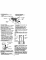
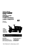
Owner's Manual
cnnFTSn#+
16.5 HP
ELECTRIC START
42" MOWER
6 SPEED TRANSAXLE
LAWN TRACTOR
Model No.
917.271110
• Safety
• Assembly
• Operation
• Maintenance
• Repair Parts
CAUTION:
Read and follow all
Safety Rules and Instructions
before operating this equipment.
Sears, Roebuck
and Co., Hoffman
For answers to your questions
about this product, Call:
1-800-659-5917
Sears Craftsman
Help Line
5 am - 5 pm, Mon - Sat
Estates,
IL 60179
Warranty .................................................
2
Safety Rules ........................................... 2
Assembly ................................................
8
Operation .............................................. 12
Maintenance Schedule ......................... 19
Maintenance ......................................... 19
Product Specifications ........................... 5
Service and Adjustments ...................... 23
Storage .................................................
29
Troubleshooting .................................... 30
Repair Parts ......................................... 34
Parts Ordering ....................... Back Cover
LIMITED TWO YEAR WARRANTY ON CRAFTSMAN RIDING EQUIPMENT
Fortwo (2) yearsfrom the dateof purchase,ifthis CraftsmanRidingEquipmentis maintained, lubricatedand tunedup accordingto the instructionsin the owner'smanual,
Searswillrepairor replace,free ofcharge, any partsfound to be defectivein matedal or
workmanship.
This Warrantydoes not cover:.
• Expendableitemswhichbecomewom duringnormaluse, suchas blades, spark
plugs,air cleaners,belts,etc.
• Tire replacementor repaircausedby puncturesfrom outsideobjects,suchas nails,
thorns,stumps,or glass.
• Repairsnecessarybecauseof operatorabuse, negligence,improperstorageor accidentor thefailureto maintainthe equipmentaccordingto the instructionscontainedin
the owner'smanual.
• Ridingequipmentusedfor commercialor rentalpurposes.
LIMITED 90 DAYWARRANTY ON BATTERY
For ninety(90) daysfrom date ofpurchase,if any batteryincludedwiththis ridingequipment provesdefectivein materialor workmanshipand ourtestingdeterminesthe batterywill not holda charge, Searswill replacethe batteryat no charge. In-homewarranty
serviceon your Craftsmanridingequipmentis availableat no chargefor 30 daysfrom
the date of purchase.Please contactyournearest servicecenter.After30 days fromthe
date of purchase,warrantyserviceis availablebytakingyourCraftsmanridingequipmentto your nearestSears ServiceCenter.(In-homewarrantyservicewill stillbe available after30 days from the date of purchasebut a standardtripchargewillapply).This
warrantyappliesonlywhilethis productis in the United States.This Warrantygivesyou
specificlegalrights, and you may also have otherrightswhichmay vary from state to
state.
Sears, Roebuckand Co., D/817 WA, HoffmanEstates,IL 60179
GENERAL
OPERATION
• Read, understand, and follow all instructions in the manual and on the machine
before starting.
• Only allow responsible adults, who are
familiar with the instructions, to operate
the machine.
• Clear the area of objects such as recks,
toys, wire, etc., which could be picked
up and thrown by the blade.
• Be sure the area is clear of other people
befO_ mowing. Stop machine if anyone
enters the area.
• Never carry passengers.
• Do not mowin reverse unlessabsolutely necessary.Alwayslookdownand
behindbeforeand whilebacking.
• Be aware of the mowerdischargedirectionand do not pointit at anyone. Do
not operatethe mowerwithouteither
the entiregrasscatcher or the guard in
place.
• Slow downbeforetuming.
• Never leavea running machineunattended.Alwaystum off blades,set parkingbrake, stop engine,and remove
keys beforedismounting.
•Tum offblades
whennotmowing.
• Stop engine beforeremovinggrass
catcheror uncloggingchute.
• Mow only in daylightor goodartificial
light.
• Do not operatethe machinewhile under
the influenceof alcoholor drugs.
• Watchfor trafficwhen operatingnear or
crossingroadways.
• Use extra care when loadingor unloadingthe machineintoa trailer or truck.
SLOPE OPERATION
• Do nottryto stabilizethe machineby
puttingyourfoot on the ground.
• Do not use grasscatcheron steep
slopes.
CHILDREN
Tragic accidentscan occurif the operator
is notalert to the presenceof children.
Childrenare oftenattractedto the
machineand the mowingactivity.Never
assumethat childrenwill remainwhere
you lastsaw them.
• Keep childrenout ofthe mowingarea
and underthe watchfulcare ofanother
responsibleadult.
• Be alsrt and rum machineoff if children
enterthe area.
• Beforeand when backing,lookbehind
and downfor smallchildren.
• Never carrychildren.They may fall off
and be seriouslyinjuredor interferewith
safe machineoperation.
• Never allowchildrento operatethe
machine.
• Use extra carewhen approachingblind
corners,shrubs,trees, or otherobjects
that may obscurevision.
SERVICE
Slopesare a majorfactor relatedto lossof-controland tipoveraccidents,which
can resultin severe injuryor death.All
slopesrequireextracaution.If you cannot
back up the slopeor if you feel uneasyon
it, do not mowit.
DO:
• Mow up and downslopes,not across.
• Removeobstaclessuchas rocks,tree
limbs,etc.
• Watch for holes, ruts,or bumps.Uneven
terraincould overtumthe machine.Tall
grass can hide obstacles.
• Use slowspeed. Choosea low gear so
that you willnot have to stopor shift
whileon the slope.
• Use extra care in handlinggasolineand
• Followthe manufacturer'srecommenotherfuels. They are flammable and
dationsfor wheel weightsor countervaporsare explosive.
weightsto improvestability.
Use onlyan approvedcontainer.
• Use extracare withgrasscatchersor
- Never removegas cap or add fuel
otherattachments.These can change
withthe engine running. Allowenthe stabilityof the machine.
gineto coolbeforerefueling.Do not
• Keep all movementon the slopesslow
smoke.
and gradual. Do not make sudden
- Never refuelthe machineindoors.
changesin speed or direction.
- Never storethe machineor fuel
• Avoidstartingor stoppingon a slope. If
containerInsidewhere there is an
tires losetraction,disengagethe blades
openflame, suchas a water heater.
and proceedslowlystraightdownthe
• Never run a machineinsidea closed
slope.
area.
DO NOT:
• Keep nutsand bolts,especiallyblade
• Do not turnon slopesunlessnecessary,
attachmentbolts,tightand keep equipand then, turnslowlyand gradually
ment in goodcondition.
downhill,if possible.
• Nevertamper withsafety devices.
• Do not mow near drop-offs,ditches,or
Check theirproperoperation regularly.
embankments.The mowercouldsud• Keep machinefree ofgrass, leaves,or
denlytum over if a wheel is overthe
otherdebrisbuild-up.Clean oilor fuel
edge of a cliffor ditch,or if an edge
spillage.Allowmachineto coolbefore
caves in.
stodng.
• Do z_ow,Qn wet grass.Reduced
• Stopand inspectthe equipmentif you
tractioncouldcause sliding.
strikean object.Repair,if necessary,
before
restarting.
• Never make adjustmentsor repairswith
the engine running.
• Grass catchercomponentsare subject
to wear, damage,and deterioration,
whichcouldexpose movingpartsor
allowobjectsto be thrown.Frequently
checkcomponentsand replacewith
manufacturer'srecommendedparis,
when necessary.
Mowerbladesare sharpand can cut.
Wrap the blade(s)or wear gloves,and
use extracautionwhen servicing them.
Check brakeoperationfrequently.
Adjustand serviceas required.
• Be sure the area is clear of otherpeople
beforemowing.Stop machineif anyone
enters the area.
• Never carry passengers.
• Do not mowin reverseunlessabsolutelynecessary.Always lookdownand
behindbeforeand whilebacking.
• Never carrychildren.They mayfall off
and be seriouslyinjuredor interferewith
safe machineoperation.
• Keep childrenout of the mowingarea
and underthe watchfulcare of another
responsibleadult.
• Be alert and turn machineoff ifchildren
enter the area.
• Beforeand when backing,lookbehind
and downfor small children.
• Mow up and downslopes(15" Max), not
across.
• Removeobstaclessuchas rooks,tree
limbs,etc.
• Watch for holes,ruts,or bumps.Uneven
terraincouldovertumthe machine. Tall
grass can hideobstacles.
• Use slow speed.Choosea low gear so
thatyou willnot have to stopor shift
whileon the slope.
• Avoidstartingor stoppingon a slope. If
tires losetraction,disengagethe blades
and proceedslowlystraightdownthe
slope.
• Do not turnon slopesunlessnecessary,
and then, turnslowlyand gradually
downhill,ifpossible.
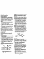
,_Look for thissymbolto pointoutimportant safetyprecautions.It meansCAUTION!!! BECOME AWARE!!!YOUR SAFETY IS INVOLVED.
_WARNING: The engineexhaustfrom
thisproductcontainschemicalsknownto
the State of Califomiato cause cancer,
birthdefects,or.otherreproductiveharm.
_ .,÷
,_CAUTION: In orderto preventaccidental startingwhen settingup,transporting,
adjustingor makingrepairsalwaysdisconnectspark plug wire and place wire where
it cannot contactspark plug.
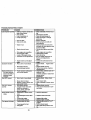
PRODUCT
SPECIFICATIONS
GASOLINE
CAPACITY
AND TYPE:
1.25 GALLONS
OIL TYPE
(API-SF/SG/SH):
SAE 30
(above 32°F)
SAE 10W-30
(below 32°F)
OIL CAPACITY:
W/RLTER: 4.0 PINTS
WK_FILTER:3.5 PINTS
SPARK PLUG:
GAP: .030")
Champion J19LM
STD361458-
UNLEADED
REGULAR
GROUND SPEED FORWARD:
(MPH):
1sr
1.1
2ND
1.4
3RD
2.3
4TM
3.5
5TM
4.5
6 TM
REVERSE:
6.0
1.7
Shouldyou experienceany problemyou
cannoteasilyremedy,please contactyour
nearest SearsAuthorizedServiceCenter.
We have competent,well-trainedtechnicians and thepropertoolsto serviceor
repairthistractor.
Please read and retainthismanual.The
instructions
willenable you to assemble
and maintainyourtractorproperly.Always
observethe "SAFETY RULES".
MAINTENANCE AGREEMENT
A Sears MaintenanceAgreementis available on this product.Contactyournearest
Sears storefor details.
CUSTOMER
RESPONSIBILITIES
• Read and observe the safety rules.
• Follow a regular schedule in maintaining, caring for and using your tractor.
• Follow the instructions under =Maintenance" and =Storage" sections of this
owner's manual.
,AWARNING: This tractor is equipped
with
an internal combustion engine and
TIRE PRESSURE: FRONT: 14 PSI
should not be used on or near any unimREAR: 10 PSI
proved forest-covered, brush-covered or
CHARGING
3 AMPS BATTERY
grass-covered land unless the engine's
SYSTEM:
5 AMPS HEADLIGHTS
exhaust system is equipped with a spark
arrester meeting applicable local or state
BATTERY:
AMP/HR: 20
laws (if any). If a spark arrester is used, it
MIN. CCA:240
should be maintained in effective working
CASE SIZE: UIR
order by the operator.
In the state of California the above is
BLADE BOLT
27-35 FT. LBS.
TORQUE:
required by law (Section 4442 of the
California Public Resources Code). Other
states may have similar laws. Federal
CONGRATULATIONSon your purchase
laws apply on federal lands. A spark
of a Craftsman Tractor. It has been
arrester for the muffler is available through
designed,engineeredand manufactured
to give you the bestpossibledependability your nearest Sears Authorized Service
Center (See REPAIR PARTS section of
and performance.
this manual).
Parts Bag contentsshownfull size
(1) Hex Bolt 5/16-18 x 1-1/4
©
(1) Hex Bolt
3/8-16 x I
(1) Lockwasher
3/8
Q
(1) Large Rat Washer
(1) Locknut 5/16-18
(1) Knol_
(1) Shoulder
Bolt 5/16-18
(1) Washer
17/32 x 1-3/16 x 12 Gauge
(2) Washers
3/16 x3/4 x 16 Gauge
(2) Hex Bolts 114-20 x3/4
liltlliillllliillllillll
(2) Screws #10 x 5/8
_.
(2)
Weld
Nuts
#10
_.
(2) Lock
Washers #10
(2) Lock
Washers 1/4 @
Nuts
(2) Hex
1/4-20
Parts packed separately in .carton
Steering
Boot
Seat
Video
Cassette
Plate
Steering
Wheel
I
Manual
Parts Bag
_(2)
(2) Shoulder
Bolts
Centerlock Nuts
(2) Washers 3/8
x 7/8 x 14 Gauge
Parts Bag contentsnot shownfull size
(2) Front LinkAssemblies
/_
_St_ri_g
Insert
in
Steering Wheel
Adapter
_).._
I
I
1
(2) Latch Hook
Assemblys
(2) Keys
Yournewtractorhasbeen assembledat the factorywith exceptionof thoseparts left
unassembledfor shippingpurposes.To ensuresafe and properoperationof yourtractor
all partsand hardwareyou assemblemustbe tightenedsecurely.Use the correcttools
as necessaryto insurepropertightness.Review the videocassettebeforeyou begin.
TOOLS REQUIRED FOR
are horizontal(leftto dght)and slide
ASSEMBLY
insidebootand ontoadapter.
• Assemblelargeflat washer,3/8 lock
A socketwrenchset willmake assembly
washer,3/8hexboltand tighten
securely.
easier.Standardwrenchsizes you need
• Snap steeringwheel insertintocenter
are listedbelow.
of steeringwheel.
(1) 9/16"wrench
(1) 3/4" Socketw/
• Remove protectivematerialsfrom trac(2) 7/16" wrenches driverachet
tor hoodand grill.
(2) 1/2" wrench
(1) PhillipsScrewIMPORTANT:Check for and removeany
(1) 3/4"wrench
driver
staplesin skidthat may puncturetires
(1) Utilityknife
(1) Tirepressure
where tractoristo rolloffskid.
(1)Pliers
gauge
Insert
When rightor left handis mentionedin
this manual,it means,from yourpointo!
view,when you are in the operatingposition(seated behindthesteeringwheel).
TO REMOVE TRACTOR FROM
CARTON
UNPACK CARTON
• Remove all accessible loose parts and
parts boxes from shipping carton (See
page 6).
• Cut, from top to bottom, along lines on
all four comers of shipping carton, and
lay panels flat.
• Remove mower and package materials.
• Check for any additional loose parts or
boxes and remove.
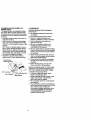
BEFORE ROLLING TRACTOR OFF
SKID
ATTACH STEERING WHEEL
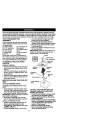
ASSEMBLE EXTENSION SHAFT AND
BOOT
- -• Slideextensionshaftontolowersteeringshaft.Alignmountingholesin extensionand lowershaftsand install5/16
hex boltand Iocknut."13ghten
securely.
IMPORTANT:Tightenboltand nut securelyto 18-22 ft. Ibs.torque.
• Placetabs of steeringbootover tab
slotsin dash and pushdownto secure.
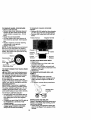
INSTALLSTEERING WHEEL
• Positionfrontwheels of the tractorso
theyare pointingstraightforward.
• Slide_eedng wheel adapteronto steering'sh_aft
extension.
• Positionsteeringwheel socross bars
Wheel
Extension
Adapter
ha.
5/16Locknut.___
LowerSteering...._
Sh .
_" :_"---,
,"--'-5" "","
\
,_/
,, t
"--._ .,-.
".._..:.
,,"
TO ROLL TRACTOR OFF SKID (See
Operation section for location and
function of controls)
• Presslift leverplungerand raiseattachmentlift leverto itshighestposition.
• Release parkingbrake by depressing
clutch/brakepedal.
• Place freewheelcontrolin freewheeling
position to disengagetransmission(See
"TOTRANSPORT"in the Operation
sectionof this manual).
• Roll tractorbackwardsoffskid.
• Remove bandingholdingdischarge
guard up againsttractor.
HOW TO SET UP YOUR
TRACTOR
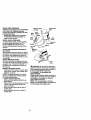
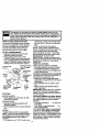
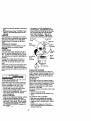
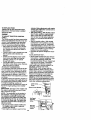
CONNECT BATTERY
ACAUTION:
Do not short battery terminals by allowing a wrench or any other
object to contact both terminals at the
same time. Before connecting battery, remove metal bracelets, wristwatch bands,
rings, etc. Positive terminal must be connected first to prevent sparking from acciclental grounding.
• Remove cardboard packing from seat
pan and lift seat pan to raised position.
• Open battery box door and remove protective plastic.
• Remove terminal protective caps and
discard.
• If this battery is put into service after
month and year indicated on label (label
located between terminals) charge battery for minimum of one hour at 6-10
amps.
• First connect RED battery cable to positive (+) terminal with hex bolt, flat washer, lock washer and hex nut as shown.
Tighten securely.
• Connect BLACK grounding cable to
negative (-) terminal with remaining hex
bolt, flat washer, lock washer and hex
nut. Tighten securely.
Discard Terminal
Seat Pan
Battery
Box Door
INSTALL SEAT
Adjust seat before tightening adjustment
knob.
• Remove cardboard packing on seat pan.
• Place seat on seat pan and assemble
shoulder bolt. Tighten shoulder bolt
securely.
• Assemble adjustment knob and flat
washer loosely. Do not tighten.
• Lower seat into operating position and
sit on seat.
• Slide seat until a comfortable position is
reached which allows you to press
clutch/brake pedal all the way down.
• Get off seat without moving its adjusted
position.
• Raise seat and tighten adjustment knob
securely.
Seat
Lock Washer
.i_ .
Proctec_ve
Hex
Flat
Washer
Seat Pan
Caps
Hex
Shoulder
Bolt _._..
Positive
(Red) Cable
=Negative
(Black)Cable
Flat Washer
Adjustment Knob
• Close batterybox door.Open battery
box doorfor:.
• inspection for secure connections
(to tightenhardware).
• Inspectionfor corrosion.
• Testingbattery.
• Jumping(if required).
• Periodiccharging.
9
CHECK
TIREPRESSURE
Weld NutFrom
Thetiresonyourtractor
wereovednflated
The Top
atthefactory
forshipping
purposes.
Lock
Correct
tirepressure
isimportant
forbest Weld Washer
cutting
performance.
Nut
• Reduce
tirepressure
toPSIshown
in
"PRODUCT SPECIFICATIONS" on
page 5 of this manual.
CHECK DECK LEVELNESS
For best cutting results, mower housing
should be properly leveled. See "TO
LEVEL MOWER HOUSING" in the
Service and Adjustments section of this
manual.
Hook Points
Down
Latch
Latch
Hook
Lock Washer
Washer
CHECK FOR PROPER POSITION OF
ALL BELTS
See thefiguresthat are shownfor replacingmotionand mowerblade drivebelts in
the Serviceand Adjustmentssectoinof
this manual.Verifythat the beltsare muted correctly.
CHECK BRAKE SYSTEM
Afteryou learnhowto operateyourtractor,checkto see that the brake is properly
adjusted.See "TO ADJUST BRAKE"in
the Service andAdjustmentssectionof
this manual.
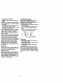
INSTALL MULCHER PLATE
• Installtwolatch hooksto mulcherplate
usingscrew,washer,lockwasher,and
weld nut as shown.
NOTE: Pre-assembleweld nutto latch
hookby insertingweld nutfrom the top
with hookpointingdown.
• Tightenhardwaresecurely.
• Raise and holddeflectorshieldin uprightposition.
• Placefront of mulcherplate over frontof
mowerdeck openingand slideinto
place, as shown.
• Hookfront latchinto-holeon front of
mower deck.
• Hookrear latchintoholeon backof
mowerdeck.
10
Mulcher
Plate
Deflector
Shield
Washer
Screw
Latch
Hooks
_CAUTION: Do not removedischarge
guard from mower.Raise and holdguard
when attachingmulcherplate and allowit
to reston plate whilein operation.
TO CONVERT TO BAGGING OR
DISCHARGING
Simplyremovemulcherplate and store in
a safe place. Yourmower is now readyfor
dischargingor installationof optional
grass catcheraccessory.
NOTE: It is notnecessaryto change
blades.The mulcherbladesare designed
for dischargingand baggingalso.
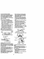
ASSEMBLE GAUGE WHEELS TO
MOWER DECK
The gauge wheels are designed to keep
the mower deck in proper position when
operating mower. Be sure they are properly adjusted to ensure optimum mower performance.
• Assemble gauge wheels with tractor on
a flat level surface.
• - Adjust mower to desired cutting height
(See "TO ADJUST MOWER CUTTING
HEIGHT" in the Operation section of this
manual).
• With mower in desired height of cut position, gauge wheels should be assembled so they are slightly off the ground.
Install gauge wheel in appropriate hole
with shoulder bolt, 3/8 washer, and 3/816 Iocknut and tighten securely.
• Repeat for opposite side installing
gauge wheel in same adjustment hole.
V' CHECKLIST
PLEASE REVIEW THE FOLLOWING•
CHECKLIST:
V' All assembly instructions have been
completed.
v' No remaining loose parts in carton.
v' Battery is properly prepared and
charged. (Minimum 1 hour at 6 amps).
v' Seat is adjusted comfortably and
tightened securely.
v' All tires are properly inflated. (For
shipping purposes, the tires were
overinflated at the factory).
v' Be sure mower deck is propedy leveled
side-to-side/front-to-rear for best cutting
results. (Tires must be properly inflated
for leveling).
v' Check mower and ddve belts. Be sure
they are routed properly around pulleys
and inside all belt keepers.
v' Check widng. See that all connections
are still secure and wires are propedy
clamped.
v' Before driving tractor, be sure freewheel control is in ddve position.
Gauge Wheel
Mounting_ racke_
_
WHILE LEARNING HOW TO USE YOUR
TRACTOR, PAY EXTRA ATTENTION TO
THE FOLLOWING IMPORTANT ITEMS:
3/8-16 Washer
Ga_-_ge_Wheel
,/ Engine oil is at proper level.
/ Fuel tank is filled with fresh, clean,
regular unleaded gasoline.
/ Become familiar with all controls - their
cation and function. Operate them
before you start the engine.
/ Be sure brake system is in safe operating condition.
/ It is important to purge the transmission
before operating your tractor for the first
time. Follow proper starting and
transmission purging instructions (See
"TO START ENGINE" and "PURGE
TRANSMISSION" in the Operation
section of this manual).
t
11
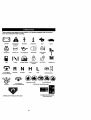
These symbolsmay appearon yourtractoror in literaturesuppliedwith the product.
Learn and understandtheirmeaning.
BATTERY
CAUTION OR
WARNING
REVERSE
ENGINE ON
ENGINE OFF
OIL PRESSURE
UGHTS ON
OVER TEMP
LIGHT
!
FUEL
CHOKE
MOWER HEIGHT
PARKING BRAKE
LOCKED
UNLOCKED
MOWER LIFT
_'l
ATrACHMENT
CLUTCH ENGAGED
_(_)
FAST
R N H L
REVERSE
NEUTRAL
ATTACHMENT
IGNITION
FORWARD
HIGH
LOW
KEEP AREA CLEAR
CLUTCH DISENGAGED
SLOW
(®)_1
PARKING BRAKE
SLOPE HAZARDS
(SEE SAFETY RULES SECTION)
HYDROSTATIC FREE WHEEL
(Hydro Mode_ onDy)
DANGER, KEEP HANDS AND FEET AWAY
12
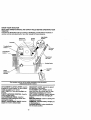
KNOWYOURTRACTOR
READ
THISOWNER'S
MANUAL
ANDSAFETY
RULES
BEFORE
OPERATING
YOUR
TRACTOR
Compare
theillustrations
withyourtractor
tofamiliarize
yourself
withthelocations
of
various
controls
andadjustments.
Savethismanual
forfuturereference.
Attachment
Clutch Lever
Ignition
Switch
LightSwitch
Position
Throttle/Choke
Control _
LiftLever
Plunger
Clutch/Brake
Control
Attachment
Lift Lever
ParkingBrake
Gearshift
Lever
Height
Adjustment
Indicator
Our tractors conform to the safety standards of the American
National Standards Institute.
ATTACHMENT CLUTCH.LEVER: Used to
engagethe mowerblades,or otherattachmentsmountedto yourtractor.
LIGHT SWITCH: Tums the headlightson
and off.
THROTTLE/CHOKE CONTROL: Used to
controlengine speed.
CLUTCH/BRAKE PEDAL: Used for
declutchingand brakingthe tractorand
startingthe engine.
HEIGHT ADJUSTMENT KNOB: Used to
adjustthe mower cuttingheight.
GEARSHIFT LEVER: Selectsthe speed
and directionof the tractor.
ATTACHMENTLIFT LEVER: Used to
raise and lowerthe mowerdeck or other
attachmentsmountedto yourtractor.
LIFT LEVER PLUNGER: Used to release
attachmentliftleverwhen changingits
position.
IGNITION SWITCH: Usedfor starting and
stoppingthe engine.
AMMETER: Indicatesbatterycharging(+)
or discharging(-).
PARKING BRAKE: Locksclutch/brake
intothe brake position.
13
The operationof any tractorcan resultin foreignobjectsthrownintothe
I
eyes,whichcan resultin severeeye damage.Alwayswear safetyglasses
or eye shieldswhileoperatingyourtractoror performingany adjustmentsor
repairs.We recommenda wide visionsafety mask over the spectacles,or
standardsafety glasses.
I
HOW TO USE YOUR TRACTOR
Yourtractoris equippedwith an operator
presencesensingswitch.When engine is
running,anyattemptby the operatorto
leavethe seat withoutfirstsettingthe
parkingbrakewillshut offthe engine.
removekey. Always removekey when
leavingtractorto preventunauthorized
USe.
• Never use choke to stop engine.
NOTE: Undercertainconditionswhen
tractoris standingidlewiththe engine running,hot engineexhaustgases may
TO SET PARKING BRAKE
cause"browning" of grass. To eliminate
• Depressclutch/brakepedal intofull
this possibility,alwaysstopenginewhen
=BRAKE"positionand hold.
ppingtractoron grassareas.
• Place parkingbrake leverin =ENCAUTION: Alwaysstop tractorcomGAGED"positionand releasepressure
pletely,as describedabove,beforeleaving
from clutch/brakepedal. Pedal should
the operator'sposition;to emptygrass
remainin =BRAKE"position.Make sure
catcher,etc.
parkingbrake will holdtractorsecure.
THROTTLE CONTROL
Attachment Clutch
Alwaysoperateengineat full throttle.
Throttle/Choke
Lever=Engaged" • Operatingengineat lessthan full throtControl
Position
tle reducesthe batterychargingrate.
•
Fullthrottle offersthe bestbaggingand
=Disengaged"
mowerperformance.
TO MOVE FORWARD AND BACKWARD
=Brake"
ParkingBrake The directionand speed of movement is
Position
,,\
controlledbythe gearshift lever.
Position
• Starttractorwith clutch/brakepedal
depressedand gearshiftlever in neutral
(N) position.
• Move gearshiftleverto desired position.
Motion
•
Slowlyreleaseclutch/brakepedalto
Pedal =Drive"
Control
start movement.
PosilJon
Position
Lever
IMPORTANT: Bringtractorto a complete
stop before shiftingor changinggears.
Failureto do so will shortenthe usefullife
STOPPING
of yourtransaxle.
MOWER BLADES.....
TO ADJUST MOWER CUTTING HEIGHT
• Move attachmentclutchlever to =DISThe cuttingheightis controlledbyturning
ENGAGED"position.
the heightadjustmentknobin desired
direction.
GROUND DRIVE • Tum knobclockwise(
) to raise cut• Depressclutch/brakepedal intofull
tingheight.
=BRAKE" position.
• Turn knob counterclockwise
(
) to
• Move gearshift lever to neutral(N) posilowercuttingheight.
tion.
The cuttingheightrange is approximately
ENGINE 1-1/2"to 4". The heightsare measured
• Move throttle controlto slow position.
from the groundto the blade tip withthe
NOTE: Failureto move throttle controlto
enginenot running. These heightsare apslow positionand allowingengineto idle
proximateand may vary dependingupon
befotL_oppir_j-may cause engineto
soilconditions,heightof grassand types
=backfire".
of grassbeing mowed.
• Turn ignition key to =OFF"positionand
\
14
• The average lawnshouldbe cutto
approximately2-1/2 inchesduringthe
coolseasonand to over 3 inchesduring
hot months. For healthierand better
lookinglawns,mowoften and after
moderategrowth.
• For bestcuttingperformance,grass
over 6 inchesin heightshouldbe
mowedtwice. Make the firstcut relativelyhigh;the secondto desired height.
TO OPERATE MOWER
Yourtractoris equippedwith an operator
presencesensingswitch. Any attemptby
the operatorto leave the seat withthe
engine runningand the attachmentclutch
engagedwill shutoffthe engine.
• Select desiredheightof cut.
• Lowermowerwith attachmentlift control.
• Startmowerbladesby engagingattachmentclutchcontrol.
• to Stop mowerblades- disengage
attachmentclutchcontrol.
,_CAUTION: Do not operatethe mower
withouteitherthe entiregrass catcher,on
mowersso equipped,or the discharge
guard in place.
Attachment Clutch
Attachment Lift
Lever "Engaged"
Position
Lever High Position
=Disengaged"
Low
Pos_on
Suard
_
OPERATE ON HILLS
CAUTION: Do not drive up or down
hills with slopes greater than 15 ° and do
not drive across any slope.
• Choose the slowest speed before starting up or down hills.
• Avoid stopping or changing speed on
hills.
• If slowing is necessary, move throttle
control lever to slower position.
• If stopping is absolutely necessary, push
clutcc,h_=l'Vbrake
j3_.dal quickly to brake posio
tiona-a-R_reng_e parking bm'ke.
• Move gearshift lever to 1st gear. Be
sure you have allowedroomfor tractor
to roll slightlyas you restartmovement.
• To restartmovement,slowlyrelease
parkingbrake and clutch/brakepedal.
• Make all tumsslowly.
TO TRANSPORT
• Raise attachmentliftto highestposition
with attachmentliftcontrol.
• When pushingor towingyourtractor,be
sure gearshiftleveris in neutral(N)
position.
• Do not pushor towtractorat more than
five (5) MPH.
NOTE: To protecthoodfrom damage
when transportingyourtractoron a truck
or a trailer,be sure hoodis closedand
securedto tractor. Use an appropriate
meansof tyinghoedto tractor(rope,cord,
etc.).
TOWING CARTS AND OTHER
A'I-rACHMENTS
Tow onlythe attachmentsthat are recommendedby and complywithspecifications
ofthe manufacturerof yourtractor.Use
commonsensewhen towing.Too heavyot
a load,whileon a slope, is dangerous.
l]res can lose tractionwiththe groundand
causeyou to losecontrolofyourtractor.
BEFORE STARTING THE ENGINE
CHECK ENGINE OIL LEVEL
• The engine in yourtractor hasbeen
shipped,from the factory, alreadyfilled
withsummer weightoil.
• Check engine oilwithtractoron level
ground.
• Unthreadand removeoilfillcap/dipstick;wipe oil off. Reinsertthe dipstick
intothe tube and restoilfill cap on the
tube. Do notthreadthe cap ontothe
tube. Remove-andread oil level. If necessary,add oiluntil =FULL_ markon
dipstickis reached. Do notoverfill.
• Forcoldweather operationyou should
change oilfor easierstarting(See "OIL
VISCOSITY CHART"in the Customer
Responsibilities
section of thismanua;).
• To changeengine oil,see the Customar
Responsibilities
sectionin this manual.
ADD GASOLINE
• Fillfuel tank. Use fresh,clean, regular
unleadedgasolinewitha minimumof 8"_
octane. (Use of leadedgasolinewill
increasecarbonand lead oxide
depositsand reducevalve life).Do not
mixoilwithgasoline.
Purchase
fuelin
WARM WEATHER STARTING (50° F
quantities
thatcanbeusedwithin30
AND ABOVE)
daystoassure
fuelfreshness.
• When engine starts,move the throttle
IMPORTANT:
Whenoperating
intempera- controlto the fast position.
turesbelow 32°F(0°C), use fresh, clean
• The attachmentsand grounddrivecan
wintergradegasolineto help insuregood
,_dAweatherstarting.
RNING: Experienceindicatesthat
alcoholblendedfuels (calledgasoholor
-usingethanolor methanol)can attract
moisturewhichleads to separationand
formationof acidsduringstorage.Acidic
gas can damage the fuel systemof an
enginewhilein storage.To avoidengine
problems,the fuel systemshouldbe emptied beforestorageof 30 days or longer.
Drainthe gas tank, startthe engine and
let it rununtil the fuel linesand carburetor
are empty.Use fresh fuel nextseason.
See Storage Instructions
for additional
information.Never use engineor carburetor cleaner productsin the fuel tankor pernent damage may occur.
CAUTION: Fillto bottomof gas tank
filler neck. Do not overfill.Wipe offany
spilledoil or fuel. Do not store,spillor use
gasolinenear an openflame.
TO START ENGINE
When startingthe enginefor the first time
or if the engine has runout of fuel,it will
take extracrankingtimeto movefuel from
the tank to the engine.
• Siton seat in operatingposition,
depressclutch/brakepedaland set
parkingbrake.
• Placegear shiftlever in neutral(N) position.
• Move attachmentclutchto =DISENGAGED" position.
• Move throttlecontrolto choke position.
Note: Beforestarting read the warm and
coldstartingproceduresbelow.
• Insertkey intoignitionand tum key
clockwiseto =START"positionand
releasekey as soonas enginestarts.
Do not run startercontinuouslyfor more
than fifteen secondsper minute.If the
engine does not startafterseveral
attempts,movethrottle controlto fast
position,wait a few minutesand try
again. If enginestilldoes not start,
movethe throttlecontrol beck to the
choke positionand retry.
16
now be used.If the enginedoes not
acceptthe load, restartthe engine and
allowit to warm up for one minuteusing
the choke as describedabove.
COLD WEATHER STARTING ( 50° F
AND BELOW)
• When engine starts,allowengine to run
with the throttlecontrolin the choke
positionuntilthe engine runsroughly,
then movethrottlecontrolto fast position. Thismay requirean engine warmup periodfrom severalsecondsto several minutes,dependingon the temperature.
• The attachmentscan also be used duringthe enginewarm-upperiod.
NOTE: If at a highaltitude(above 3000
feet) or in coldtemperatures(below32 F)
the carburetorfuel mixturemay need to be
adjustedfor best engineperformance.
See =TOADJUST CARBURETOR"in the
Serviceand Adjustmentssectionof this
manual.
MOWING TIPS
• "13re
chainscannotbe used when the
mowerhousingis attachedto tractor.
• Mowershouldbe properlyleveledfor
bestmowingperformance.See =TO
LEVEL MOWER HOUSING"in the
Serviceand Adjustmentssectionof this
manual.
• The lefthand sideof mowershouldbe
usedfor trimming.
• Driveso thatclippingsare discharged
ontothe area that hasbeen cut. Have
the cut area to-the rightof the tractor.
This willresultin a more even distribution ofclippingsand more uniformcutting.
• When mowing large areas, start by turning to the right so that clippings will discharge away from shrubs, fences, driveways, etc. After one or two rounds, mow
in the opposite direction making left
hand tums until finished.
• If grass is extremely tall, it should be
mowed twice to reduce load and possible fire hazard trom dried clippings.
Make first cut relatively high; the second
to the desired height.
• Do not mow grass when it is wet. Wet
grass will plug mower and leave undesirable clumps. Allow grass to dry
before mowing.
• Always operate engine at full throttle
when mowing to assure better mowing
performance and proper discharge of
material. Regulate ground speed by selecting a low enough gear to give the
mower the best cutting performance as
well as the quality of cut desired.
• When operating attachments, select a
ground speed that will suit the terrain
and give best performance of the attachment being used.
MULCHING
MOWING
TIPS
IMPORTANT: For best performance, keep
mower housing free of built-up grass and
trash. Clean after each use.
• The special mulching blade will recut
the grass clippings many times and
reduce them in size so that as they fall
onto the lawn they will disperse into the
grass and not be noticed. Also, the
mulched grass will biodegrade quickly
to provide nutrients for the lawn. Always
mulchwithyour highestengine (blade)
speed as thiswill providethe best recuttingactionof the blades.
Avoidcuttingyourlawn when it iswet.
Wet grass tendsto form clumpsand
interfereswith the mulchingaction.The
best timeto mow yourlawn isthe early
!
,'
I
I,
aftemoon.At this time the grasshas
dried and the newlycut area willnot be
exposedto the directsun.
• For bestresults,adjustthe mowercutting heightsothat the mowercutsoff
only the top one-thirdofthe grass
blades. Forextremelyheavymulching,
reduceyourwidthofcut on each pass
and mow slowly.
• Certaintypes of grassand grassconditionsmay requirethat an area be
mulcheda secondtimeto completely
hidethe clippings.When doinga second cut, mowacross or perpendicularto
the first cut path.
• Change yourcuttingpatternfrom week
to week. Mow northto southone week
then changeto east to west the next
week. This willhelp preventmattingand
grainingof the lawn.
17
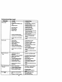
CUSTOMER RESPONSIBILITIES
MAINTENANCE
AS YOU
SCHEDULE
_./_
__..,,,__.,,_€.J
COMPLETE
DATES
lie
Check Brake
Check
T
R
Operation
t_
Tire Pressure
I_
i Check Operator Presence
: Intedock Systems
and
V °
CheckforLooseFa_enera
SharperdIReplace
V p
Mower
V*
I,/,
Blades
T LuStre.on
Chart
Check Battery Level
Clean Battery and Terminals/Recharge
Check Transaxla
Ad}ust Blade
Check
I/
V r
V _
Cooling
Drive Ball(s)
Ks
Tension
Engine Oil Level
Change
V'
Belt(s) Tension
Adjust Motion
Engine
I_s
V °
V °
Oil
IV_1_.3
E
Clean
Air Filter
i V'2
Air Screen
! V_2
N
Clean
G
Inspect Muffler/Spark
Arraster
Replace Oil Filter (If equipped)
N
Clean
Engine
l/
V_4
Co_ing
V*
I_
V_1.2
Fins
Replace
Spark
Replace
Air Filter Paper
Replace
Fuel Filter
VP2
Plug
If
Cartridge
V'
1 - Change more often when operstlng undM a heavy load or in high ambient
2 - Service more o/len when opeflmting ;n dirty cx dusty €ondltlons.
3 - If equipped v*l_ o;I rdtwo Ohange oil evely 50 hourL
4 - Replace blmdN more oqtenwhon _
ll_
V_2
in sandy soil.
tempeqat_r_.
5 * If equipped with adjustable
systern.
6 - Not required if equipped with rnalntenance-_ee
7 - Tighten front rode plvol bon to 35 ft.-Ibs, _.
better,/.
Do no__.
GENERAL RECOMMENDATIONS
LUBRICATION CHART
O Spindle
The warrantyon this tractordoes not cover
Zerk
itemsthat havebeen subjectedto operator
abuse or negligence.To receivefullvalue
from thewarranty,operatormust maintain
tractoras instructedin thismanual. Some
O FrontWheel
Wheel
adjustmentswillneed to be made periodi- BearingZerk
Bearing
Zerk
callyto properlymaintainyourtractor.
All adjustmentsin the Serviceand
Adjustmentssectionofthis manualshould 0 Enc
be checkedat least once each season.
• Once a year you shouldreplacethe
Attachment_ :
sparkplug,clean or replaceair filter,and 0Clutch
• Gear
checkbladesand belts for wear.A new
Pivot(s)
_ "-_"
T-_ _
Shift
sparkplug and clean air filter assure
......
Pivots
properair-fuelmixtureand helpyour
O SAE 30 or 10w30 MotorOIL
engine runbetterand last longer.
e General PurposeGrease
BEFORE EACH USE
@ Referto Maintenance"Engine"Section
•
•
•
•
Check engineoil level.
Check brake operation.
Check tire pressure.
Ch_k operatorpresenceand interlock
sys_'d_ fo_lSroperoperation.
• Check for loosefasteners.
IMPORTANT: Do not oil or grease the pivot
points which have special nylon bear-ings.
Viscous lubricants will attract dust and dirt
that will shorten the life of the self-lubricating
bearings. If you feel they must be lubricated,
use only a dry, powdered graphite type lubricant sparingly.
18
TRACTOR
Alwaysobservesafety ruleswhen performingany maintenance.
BRAKE OPERATION
If tractor requires more than six (6) feet
stopping distance at high speed in highest
gear, then brake must be adjusted. (See
"TO ADJUST BRAKE" in the Service and
Adjustments sectionof this manual).
TIRES
• Maintain proper air pressure in all tires
(See "PRODUCT SPECIFICATIONS"
on page 5 of this manual).
• Keep tires free of gasoline, oil, or insect
control chemicals which can harm rubber.
• Avoid stumps, stones, deep ruts, sharp
" objects and other hazards that may
cause tire damage.
NOTE: To seal tire punctures and prevent
flat tires due to slow leaks, tire sealant
may be purchased from your local parts
dealer. Tire sealant also prevents tire dry
rot and corrosion.
BLADE CARE
For best results mower blades must be
kept sharp. Replace bent or damaged
blades.
BLADE REMOVAL
• Raise mower to highest position to allow
access to blades.
• Remove hex bolt, lock washer and flat
washer securing blade.
• Install new or resharpened blade with
trailing edge up towards deck as shown.
• Reassemble hex bolt, lock washer and
fiat washer in exact order as shown.
• "13ghtenbolt securely (30-35 Ft. Lbs.
torque).
IMPORTANT: Blade b01t'is-Grade 8 heat
treated.
Assembly
FlatWas
Bladher___
•oc.
Trailing
Mandrel
Edge Up
Hex Bolt(Grade 8)_.._
*A Grade 8 heat treated bolt can be
ide!;l_,
by,_x lines on the bolt head.
TO SHARPEN BLADE
NOTE: We do not recommend sharpening
blade, butif you do, be sure the blade is
balanced.
Care should be taken to keep the blade
balanced. An unbalanced blade will cause
excessive vibration and eventual damage
to mower and engine.
• The blade can be sharpened with a file
or on a grinding wheel. Do not attempt
to sharpen while it is on the mower.
• To check blade balance, you will need a
5/8" diameter steel bolt, pin, or a cone
balancer. (When using a cone balancer,
follow the instructions supplied with balancer).
NOTE: Do not use a nail for balancing
blade. The lobes of the center hole may
appear to be centered, but are not.
• Slide blade onto an unthreaded portion
of the steel bolt or pin and hold the bolt
or pin parallel with the ground. If blade
is balanced, it should remain in a horizontal position. If either end of the blade
moves downward, sharpen the heavy
end until the blade is balanced.
CenterHole
Blade
5/8" Bolt
or Pin
BATTERY
Yourtractorhas a batterychargingsystem
whichis sufficientfor normaluse.
However,periodicchargingof the battery
withan automotivechargerwill extendits
life.
• Keep battery and terminalsclean.
• Keep battery boltstight.
• Keep small vent holesopen.
• Recharge at 6-10 amperes for 1 hour.
TO CLEAN BATTERYAND TERMINALS
Corrosionand dirton the batteryand terminalscan cause the batteryto "leak"
power.
• Open battery boxdoor.
• DisconnectBLACKbatterycablefirst
then RED batterycable and remove
batteryfrom tractor.
• Rinsethe batterywith plainwater and
dry.
• Clean terminalsand batterycable ends
with wire brush untilbright.
19
• Coat terminals with grease or petroleum
jelly.
• Reinstall battery (See =CONNECT BATTERY" in the Assembly section of this
manual).
V-BELTS
Check V-belts for deterioration and wear
after 100 hours of operation and replace if
necessary. The belt3 are not adjustable.
Replace belts if they begin to slip from
wear.
TRANSAXLE COOLING
Keep transaxle free from build-up of dirt
and chaff which can restrict cooling.
ENGINE
LUBRICATION
Only use high quality detergent oil rated
with API service classification SF, SG, or
SH. Select the oil's SAE viscosity grade
according to your expected operating temperature.
Change the oil alter every 50 hours of
operation or at least once a year if the
tractor is not used for 50 hours in one
year.
Check the crankcase oil level before starting the engine and after each eight (8)
hours of operation. Tighten oil fill cap/dipstick securely each time you check the oil
level.
SAE VISCOSITY
T()_HANGE _N_'E
GRADES
O_
Determinetemperaturerangeexpected
beforeoilchange. All oilmustmeet API
serviceclassificationSF, SG, or SH.
• Be sure tractoris on level surface.
• Oil willdrain morefreely when warm.
• Catch oilin a suitablecontainer.
• Remove oilfillcap/dipstick.Be careful
not to allowdirtto enter the engine
when changingoil
• Remove drainplug.
• After oil has drainedcompletely,replace
oil drain plugand tightensecurely.
• Refillenginewith o=3
throughoilfill dipsticktube. Pourslowly. Do not overfill.
For approximatecapacitysee =PRODUCT SPECIFICATIONS"on page 3 of
this.ro,_, al..;... _
• Use gauge on oil till cap/dipstick for
checking level. Insert dipstick into the
tube and rest the oUfill cap on the tube.
Do not thread the cap onto the tube
when taking reading. Keep oil at
=FULL= line on dipstick. Tighten cap
onto the tube securely when finished.
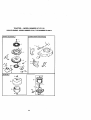
Air Cleaner
Cover
CoverKnob
Wing Nut
Foam
Pre-Cleaner
Air
Cleaner
Base
Oil Fill
Cap/
Dipstick
Air Cleaner
Paper
Cartridge
Oil Drain Plug
CLEAN AIR SCREEN
Air screen must be kept free of dirt and
chaff to prevent engine damage from overheating. Clean with a wire brush or compressed air to remove dirt and stubborn
dried gum fibers.
AIR FILTER
Your engine will not run properly using a
dirty air filter. Clean the foam pre-cleaner
after every 25 hours of operation or every
season. Service paper cartridge every
100 hours of operation or every season,
whichever occurs-flrst.
Service air cleaner more often under dusty
conditions.
• Remove knob and cover.
• Remove wing nut and air cleaner from
base.
TO SERVICE PRE-CLEANER
• Slidefoam pre_leaner offcartridge.
• Wash it in liquiddetergentand water.
• Squeeze itdry in a cleancloth. Allow it
to dry.
• Saturateit in engineoil. Wrap itin
clean,absorbentclothand squeezeto
removeexcessoil.
2O
TOSERVICE
CARTRIDGE
IN-LINE
• Replace a dirty, bent, or damaged cartridge.
NOTE: Do not wash the paper cartridge
or use pressurized air, as this will damage
the cartddge.
• Reinstall the pre-cleaner (cleaned and
oiled) over the paper cartridge.
• Reassemble air cleaner, wing nut, cover
and tighten knob securely.
CLEAN AIR INTAKFJCOOLING AREAS
To insure proper cooling, make sure the
grass screen, cooling fins, and other
external surfaces of the engine are kept
clean at all times.
Every 100 hours of operation (more often
under extremely dusty, dirty conditions),
remove the blower housing and other
cooling shrouds. Clean the cooling fins
and external surfaces as necessary. Make
sure the cooling shrouds are reinstalled.
NOTE: Operating the engine with a
blocked grass screen, dirty or plugged
cooling fins, and/or cooling shrouds removed will cause engine damage due to
overheating.
The fuel filter should be replaced once
each season. If fuel filter becomes
clogged, obstructing fuel flow to carburetor, replacement is required.
• With engine cool, remove filter and plug
fuel line sections.
• Place new fuel filter in position in fuel
line with arrow pointing towards carburetor.
• Be sure there are no fuel line leaks and
clam.ps are properly positioned.
_
FUEL FILTER
Filter
CLEANING
• Clean engine, battery, seat, finish, etc.
of all foreign matter.
• Keep finished surfaces and wheels free
of all gasoline, oil, etc.
• Protect painted surfaces with automotive type wax.
We do not recommend using a garden
hose to clean your tractor unless the electrical system, muffler, air filter and carburetor are covered to keep water out. Water
in engine can result in a shortened engine
life.
MUFFLER
Inspectand replacecorrodedmufflerand
sparkarrester(if equipped)as itcouldcreate a fire hazard and/or damage.
SPARK PLUGS
Replacespark plugsat the beginningof
eachmowingseason or after every 100
hoursof operation,whicheveroccursfirst.
Sparkplug type and gap settingare
shownin =PRODUCT SPECIFICATIONS"
on page 5 of this manual.
21
,_CAUTION:
Before pedorming any service or adjustments:
• Depress clutch/brake pedal fully and set parking brake.
• Place motion control lever in neutral (N) position.
• Place attachment clutch in "DISENGAGED" position.
• Turn ignition key "OFF" and remove key.
* Make sure the blades and all moving pads have completely stopped.
• Disconnect spark plug wire from spark plug and place wire where it cannot come
in contact with plug.
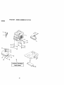
TO REMOVE MOWER
Mowerwillbe easier to removefrom the
rightside oftractor.
• Placeattachmentclutchin =DISENGAGED"position.
• Move attachmentlift leverforwardto
lowermowerto itslowestposition.
• Rollbelt offengine pulley.
• Disconnectclutchrodfrom clutchlever
by removingretainerspring.
• Disconnectanti-swaybarfrom chassis
bracketby removingretainerspring.
• Disconnectsuspensionarms from rear
deckbracketsby removingretainer
spdngs.
• Disconnectfrontlinksfrom deckby
removingretainersprings.
• Raise lift leverto raisesuspension
arms. Slidemower outfrom undertractor.
IMPORTANT: Ifan attachmentotherthan
the mowerdeckis to be mountedon the
tractor,removethe frontlinks.
TO INSTALL MOWER
• Raise attachmentliftlever to itshighest
position.
• Slidemower undertractorwithdischargeguard to rightside of tractor.
• Lowerliftlever to its lowestposition.
• Installmowerin reverseorder of
removalinstructions.
Clutch Lever
Retainer
Spring
Clutch
EnginePulley
Suspension Arms
Front Link
Retainer Springs
(Both Sides)
Retainer
Spring
SuspensionArm
Anti-Swaybar
RetainerSpdngs
(Both Sides)
22
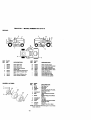
TO LEVEL MOWER HOUSING
Adjustthe mowerwhiletractoris parked
on levelgroundor driveway. Make sure
tiresare properlyinflated(See =PRODUCT SPECIFICATIONS'). If tires are
over or underinflated,you willnot propedy
adjustyourmower.
SIDE-TO-SiDE ADJUSTMENT
• Raise mowerto itshighestposition.
° At the midpointof bothsides of mower,
measureheightfrom bottomedge of
mowerto ground. Distance=A"on both
sidesof mower shouldbe the same or
within1/4" of each other.
• If adjustmentis necessary,make adjustmenton one side of mower only.
° To raise one side of mower,tightenlift
linkadjustmentnut on thatside.
° To lowerone side of mower,loosenlift
linkadjustmentnut on that side.
NOTE: Eachfull tum of adjustmentnut
willchangemowerheightabout 1/8".
• Recheckmeasurementsafter adjusting.
• Beforemakingany necessaryadjustments, checkthatbothfront linksare
equal in length. Bothlinksshouldbe
approximately10-3/8".
• If linksare not equal in length,adjust
one linkto same lengthas otherlink.
• To lowerfront of mowerloosennut =E"
on bothfront linksan equal numberof
tums.
• When distance=D"is 1/8"to 1/2"lower
at front than rear,tightennuts =P
againsttrunnionon bothfront links.
• To raisefront of mower,loosennut =P
from trunnionon bothfront links.
Tightennut =E"on bothfront linksan
equal numberoftums.
• When distance=D"is 1/8"to 1/2"lower
at front than rear,tightennut =P against
trunnionon bothfront links.
• Recheckside-to-sideadjustment.
ndrel
Bottom
Bottom
BothFrontLinksShouldbe Equalin Length
of Cud_
f Curt
t- 7GroundLine
(_
_--j-r _
Suspension
Trunnion
Lift Link Adjustment Nut
FRONT-TO-BACKADJUSTMENT
IMPORTANT: Deck mustbe level side-toside. If the followingfront-to-back adjustment is necessary,be sure to adjust both
front links equally so mower will stay
level side-to-side.
To obtainthe bestcuttingresults,the
mowerhousingshouldbe adjustedso that
the front is approximately1/8" to 1/2"
lowerthan the rear when the mower is in
itshighestposition.
Check adjustmenton rightside oftractor.
Measuredistance=D"directlyin front and
behind.,tti_mandrelat bottomedge of
mowerh_usingas shown.
Front Links
Trunnion
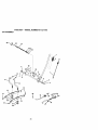
TO REPLACE MOWER BLADE DRIVE
BELT
The mower blade drive belt may be
replaced without tools. Park the tractor on
level surface. Engage parking brake.
BELT REMOVAL • Remove mower from tractor (See "TO
REMOVE MOWER" in this section of
this manual).
• Work belt off both mandrel pulleys and
idler pulleys.
• Pull belt away from mower.
23
BELT
INSTALLATION
-
and inside all belt guides.
• Install mower in reverse order of
removal instructions.
• Install new belt in reverse order of
removal.
• Make sure belt is in all pulley grooves
Idler Pulley
IdlerPulley
Mandrel
Mandrel
Pulley
TO ADJUST BRAKE
Your tractor is equippe_ with an adjustable
brake system which is mounted on the
right side of the transaxle.
If tractor requires more than six (6) feet
stopping distance at high speed in highest
gear, then brake must be adjusted.
• Depress clutch/brake pedal and engage
parking brake.
• Measure distance between brake operating arm and nut =A" on brake rod.
• If distance is other than 1-1/2", loosen
jam nut and turn nut "A" until distance
becomes 1-1/2". Retighten jam nut
against nut =A".
• Road test tractor for proper stopping
distance as stated above. Readjust if
necessary. If stopping distance is still
greater than six (6) feet in highest gear,
further maintenance is necessary.
Contact your nearest authorized service center/department.
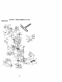
TO REPLACE MOTION DRIVE BELT
Nut "A"
With ParkingBrake
//
Clutching Idler /
Stationary /
Idler
i
Locator
Tab
Upper Belt
Keeper
Transmission
)
TO ADJUST STEERING WHEEL ALIGNMENT
If steeringwheel crossbarsare not horizontal (leftto right)when wheelsare positionedstraightforward, removesteering
wheel and reassembleper instructions
in
theAssemblysectionof thismanual.
FRONT WHEEL TOE-IN/CAMBER
The front wheel toe-inand camberare not
adjustableon yourtractor.If damage has
occurredto affectthe frontwheeltoe-inor
camber,contactyournearestauthorized
servicecenter.
Jam Nut
Park the tractor on level surface. Engage
parking brake. For assistance, there is a
belt installation guide decal on bottom side
of left footrest.
• RemOV'_rnower (See =TO REMOVE
MOWER" in this section of this manual.)
• Remove upper belt keeper.
Engine
Pulley
Input Pulley _=
_ _Engaged"
•
• Remove beltfrom stationaryidlerand
clutchingidler.
• Pullbelt slacktowardrear oftractor.
Remove belt upwardsfrom transaxle
pulleybydeflectingbelt keepers.
• Pullbelt towardfront oftractorand
removedownwardsfrom aroundengine
pulley.
• Installnew belt by reversingabove procedure.
IMPORTANT: Make sure upper belt keeper is positionedproperlybetweenlocator
tab.
24
TOREMOVE
WHEEL
FORREPAIRS
• Block up axle securely.
• Remove axle cover, retaining ring and
washers to allow wheel removal (rear
wheel contains a square key - Do not
lose).
• Repair tire and reassemble.
• On rear wheels only: align grooves in
rear wheel hub and axle. Insert square
key.
• Replace washers and snap retaining
ring securely in axle groove.
• Replace axle cover.
NOTE: To seal tire punctures and prevent
flat tires due to slow leaks, tire sealant
may be purchased from your local parts
dealer. 13re sealant also prevents tire dry
rot and corrosion.
WashersA
RetainingRing _ ff/'__
Square Key _'
(Rear Wheel Only)
TO REMOVE CABLES, REVERSE
ORDER • Remove BLACK cable first from chassis
and then from the fully charged battery.
- Remove RED cable last from both battedes.
Positive Terminal
NegativeTerminal
Charged
Ballet
Positive
Terminal
Negative
Terminal
TO REPLACE HEADLIGHT BULB
• Raise hood.
• Pull bulb holder out of the hole in the
backside of the grill.
• Replace bulb in holder and push bulb
holder securely back into the hole in the
backside of the gdll.
• Close hood.
TO REMOVE HOOD AND GRILL ASSEMBLY
• Raise hood.
• Unsnap headlight wire connector.
• Stand in front of tractor. Grasp hood at
sides, tilt toward engine and lift off of
tractor.
• To replace, reverse above procedures.
"_'_"
TO START ENGINE THAT HAS A WEAK
BATTERY
_CAUTION:
Lead-acid batteries generate explosive gases. Keep sparks, flame
and smoking materials away from batteries. Always wear eye protection when
around batteries.
If your battery is too weak to start the
engine, it should be recharged. If "jumper
cables" are used for emergency starting,
follow this procedure:
IMPORTANT: Your tractor is equipped
with a 12 volt negativ e grounded system.
The other vehicle must also be a 12 volt
negative grounded system. Do not use
your tractor battery to start other vehicles.
\
TO ATTACH JUMPER CABLES • Connect each end of the RED cable to
the POSITIVE (+) terminal of each battery, taking care not to short against
chassis.
• Connect one end of the BLACK cable to
the NEGATIVE (-) terminal of fully
charged battery.
• Connect the other end of the BLACK
cabk_to goed CHASSIS GROUND,
away from fuel tank and battery.
Headlight Wire
Connector
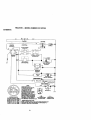
INTERLOCKS AND RELAYS
Loose or damaged wiring may cause your
tractor to run poody, stop running, or prevent it from starting.
• Check wiring. See electrical widng diagram in the Repair Parts section of this
manual.
25
TOREPLACE
FUSE
Replace
with30ampautomotive-type
plug-in
fuse.Thefuseholder
islocated
behind
thedash.
ENGINE
TO ADJUST THROI"FLE CONTROL
CABLE
The throttle control has been preset at the
factory and adjustment should not be necessary. Check adjustment as described
below before loosening cable. If adjustment is necessary, proceed as follows:
• With engine not running, move throttle
control lever from slow to choke position. Slowly move lever from choke to
fast position.
• Check to see if hole in throttle lever and
hole in speed control bracket are
aligned.
• If holes are not aligned, loosen cable
clamp screw and align the holes by
inserting a pencil or a 1/4" ddll bit
through both holes.
• Pull throttle cable up to remove slack
and tighten cable clamp screw. Remove
alignment pencil or drill bit.
TO ADJUST CARBURETOR
The carburetor has been preset at the factory and adjustment should not be necessary. However, minor adjustment may be
required to compensate for differences in
fuel, temperature, altitude or load. If the
carburetor does need adjustment, proceed
as follows:
In general, turning the adjusting needles in
(clockwise) decreases the supply of fuel to
the engine giving a leaner fueVair mixture.
Turning the adjusting needles out
(counterclockwise) increases the supply of
fuel to the engine giving a richer fueVair
mixture.
-,
IMPORTANT: Damage tothe needlesand
the seatsincarburetor
may result
ifneedleisturnedintootight.
NOTE: The carburetoron thisengine is
low emission.Itisequippedwithan idle
fueladjusting
needlewitha limiter
cap,
which allowssome adjustmentwithinthe
limits
allowedby thecap. Do notattempt
to remove the limiter
cap.The limiter
cap
cannot be removed withoutbreakingthe
adjusting
needle.
• Be sure you have a clean air filter and
the tl=vr_ttecontrol cable is adjusted
properly (see above).
• Start engine and allow to warm for five
minutes. Make adjustments with engine
running and shift/motion control lever in
neutral (N) position.
• Idle speed setting - With throttle control
lever in slow position, engine should
idle at 1750 RPM. If engine idles too
slow or fast, turn idle speed adjusting
screw in or out until correct idle is attained.
• Idle fuel needle setting - With throttle
control lever in slow position, turn idle
fuel adjustment needle in (clockwise)
until engine begins to die and then turn
out (counterclockwise) until engine runs
rough. Tum needle to a point midway
between those two positions.
• Recheck idle speed. Readjust if necessary.
ACCELERATION TEST • Move throttle control lever from slow to
fast position. If engine hesitates or dies,
turn idle fuel adjusting needle out
(counterclockwise) 1/8 rum. Repeat test
and continue to adjust, if necessary,
until engine accelerates smoothly.
High speed stop is factory adjusted. Do
not adjust - damage may result.
IMPORTANT: Never tamper with the
engine governor, which is factory set for
proper engine speed. Overspeeding the
engine above the factory high speed setting can be dangerous. If you think the
engine-governed high speed needs
adjusting, contact your nearest AUTHORIZED service center/department, which
has proper equipment and experience to
make any necessary adjustments.
Cable Clamp
Screw
Speed ControlBracket
ThrottleLever
Idle Speed
Adjusting
Screw
Idle Fuel
AdjuslJng
Needle
26
Immediatelyprepareyourtractorfor storage at the end ofthe seasonor ifthe tractor willnot be used for 30 daysor more.
_CAUTION: Never store thetractorwith
gasolinein the tank insidea building
where fumesmay reach an openflame or
spark. Allowthe engineto coolbefore
storingin any enclosure.
TRACTOR
Remove mowerfrom tractorfor winter
storage.Thiswill allowyouto clean itthoroughly.Removeall dirt,grease, leaves,
etc. Store in a clean, dry area.
• Clean entiretractor(See "CLEANING"
in the Maintenancesectionof thismanual).
• Inspectand replacebelts,if necessary
(See belt replacementinstructionsin the
Service andAdjustmentssectionof this
manual).
• Lubricateas shownin the Maintenance
sectionof this manual.
• Be sure thatall nuts,boltsand screws
are securelyfastened.Inspectmoving
parts for damage,breakageand wear.
Replaceif necessary.
• Touchup all rustedor chippedpaintsurfaces; sand lightlybeforepainting.
BATTERY
• Fullychargethe batteryfor storage.
• After a periodof time in storage,battery
may requirerecharging.
• To help preventcorrosionand power
leakage duringlongperiodsof storage,
batterycablesshouldbe disconnected
and batterycleanedthoroughly(see
=-I0 CLEAN BATTERYAND TERMINALS"in the Maintenancesectionof
this manual).
• After cleaning,leavecablesdisconnected and placecables where theycannot
come in contactwithbatteryterminals.
• If batteryis removedfrom tractorfor
storage, do not store batterydirectlyon
concreteor damp surfaces.
ENGINE
blendedfuels (calledgasohoior using
ethanolor methanol)can attractmoisture
whichleads to separation and formationof
acidsduringstorage.Acidicgas can damage the fuel systemof an enginewhilein
storage.
• Drain the fuel tank.
• Startthe engineand let it run untilthe
fuel linesand carburetorare empty.
• Never use engineor carburetorcleaner
productsin thefuel tank or permanent
damage may occur.
• Use fresh fuel next season.
NOTE: Fuelstabilizeris an acceptable
alternativein minimizingthe formation of
fuel gum depositsduringstorage.Add stabilizerto gasolinein fuel tank or storage
container.Alwaysfollow the mix ratio
found on stabilizercontainer.Run engine
at least 10 minutesafteraddingstabilizer
to allowthe stabilizerto reachthe carburetor.Do not drainthe gastank and carburetor if usingfuel stabilizer.
ENGINE OIL
Drain oil (withengine warm)and replace
with clean engineoil. (See "ENGINE"in
the Maintenancesectionof this manual).
CYLINDERS
• Remove sparkplug(s).
• Pour one ounceof oilthroughspark
plug hole(s)intocylinder(s).
• Turn ignitionkey to =START"positionfor
a few secondsto distributeoil.
• Replace withnew spark plug(s).
OTHER
• Do not store gasolinefrom one season
to another. ....
• Replaceyourgasolinecan if it startsto
rust.Rustand/ordirtin your gasoline
willcause problems.
• If possible,storeyourtractorindoors
and cover itto give protectionfrom dust
and dirt.
• Coveryourtractorwitha suitableprotectivecoverthat does not retain moisture. Do not use plastic.Plasticcannot
breathe,whichallowscondensationto
formand causeyourtractorto rust.
IMPORTANT: Never covertractorwhile
engine and exhaustareas are stillwarm.
FUEL SYSTEM
IMPORTANT: It is important to prevent
gum deposits from forming in essential
fuel system parts such as carburetor, fuel
filter, _ose,_or
tank during storage.
Also, experience indicates that alcohol
27
TROUBLESHOOTING
CHART
PROBLEM
Will not start
CAUSE
CORRECTION
• Out of fuel.
• Engine not'CHOKED"
prop
e_.
• Engine flooded.
• Bad spark plug.
• Dirty air filter.
• Dirty fuel filter.
• Water in fuel.
• Loose or damaged wiring.
• Carburetor out of adjustment.
•
Hard to start
• Dirty air filter.
• Bad spark plug.
• Weak or dead battery.
• Dirty fuelfilter.
• Stale or dirty fuel.
• Loose or damaged wiring.
• Carburetor out of adjustment.
•
Engine wi, not turn
over
Engine valves out of adjustment.
Engine valves out of adjustment.
• Clutch/brake pedal not
depressed.
• Attachment clutch is engaged.
• Weak or dead battery.
• Blown fuse.
• Corroded battery terminals.
• _,.Looseor damaged wiring.
• Faulty ignition switch.
•
•
Faulty solenoid or starter.
Faulty operator presence
switch(es).
Engine dicks but will
not start
Loss Of power
• Weak or dead battery.
• Corroded battery terminals.
• Loose or damaged wiring.
• Faulty solenoid or starter.
•
Cuffing too much grass/too
fast.
• Throttle in "CHOKE" position.
28
• Figfuel tank.
• See "TO START ENGINE"in
Operationsection.
• Wait several minutesbefore
attemptingto start.
• Replacesparkplug.
• Clean/replaceair filter.
• Replacefuelfilter.
• Drainfueltank andcarburetor,
refilltankwithfresh
gasolineand replacefuel filter.
• Check all wiring.
• See "ToAdjustCarburetor"in
ServiceandAdjustments
section.
• Contact an authorizedservice
center.
• Clean/replace air filter.
• Replace spark plug.
• Recharge or replace battery.
• Replace fuel filter.
• Drain fuel tank and refill with
fresh gasoline.
• Check all wiring.
• See "To Adjust Carburetor" in
Service and Adjustments
section.
• Contact an authorized service
center.
Depressclutch/brakepedal.
•
•
•
•
•
•
•
Disengageattachmentclutch.
Rechargeor replacebattery.
Replacefuse.
Clean batteryterminals.
Checkail widng.
Check/replaceignitionswitch.
Check/replacesolenoid or
starter.
• Contact an authorizedservice
center.
• Rechargeor replacebattery.
• Clean batteryterminals.
• Check all wiring.
• Check/replace solenoid or
starter.
• Set in "Higher Cut" position/reduce speed.
• Adjust throttle control.
TROUBLESHOOTING
CHART
CAUSE
PROBLEM
Lose
ofpower
(cont'd)• Build-up
CORRECTION
of grass, leaves and
trash under mower.
• Dirty fuel filter.
• Stale or dirty fuel.
ing.
• Clean/replace air filter.
• Check oil level/change oil.
• Clean and regap or change
spark plug.
• Replace fuel filter.
• Drain fuel tank and refill with
• Water in fuel.
fresh gasoline.
• Drain fuel tank and carburetor,
• Dirty air filter.
• Low oil level/dirty oil.
• Faulty spark plug.
• Spark plug wire loose.
•
•
•
•
Dirty engine air screen/fins.
Dirty/clogged muffler.
Loose or damaged wiring.
Carburetor out of adjustment.
• Engine valves out of adjustment.
Excessivevibration
Engine continues to
run when operator
leaves seat with attachment clutch
engaged
Poor cut - uneven
Mower blades will not
rotate
Poor grass discharge
refill tank with fresh gasoline and
replace fuel filter.
• Connect and tighten spark plug
wire.
•
•
•
•
Clean engine air screen/fins.
Clean/replace muffler.
Check all wiring.
See =To Adjust Carburetor" in
Service and Adjustments
section.
• Contact an authorized service
center.
• Worn, bent or loose blade.
• Replace blade.
bolt.
• Bent blade mandrel.
• Loose/damagedpart(s).
•
• Faultyoperator-safetypresence controlsystem.
Tighten blade
Replace blade mandrel.
• Tighten loose part(s). Replace
Jama_led parts.
• Check wiring, switches and connections. If not
corrected, contact an authorized
service center/
• Worn, bent or loose blade.
Mower deck not level.
Poorcut - uneven
(conrd)
• Clean underside of mower hous-
Buildup of grass, leaves, and
trash under mower.
Bent blade mandrel.
Clogged mower deck vent
holes from buildup of
grass, leaves, and trash
around mandrels.
Obstruction in clutch mechanism.
department.
Replace blade. Tighten blade
bolt.
• Level mower deck.
• Clean underside of mower hous•
ing.
• Replace blade mandrel.
• Clean.mound mandrels to open
vent holes.
• Remove obstruction.
Worn/damaged mower drive
belt.
• Replace mower drive belt.
Frozen idler pulley.
Frozen blade mandrel.
• Replace idler pulley.
• Replace blade mandrel.
• Place throttle control in "FAST"
Engine speed too slow.
positS.
Travel speedtoo fast.
Wet grass.
29
• Shift to dower speed.
• Allow grass to dry before mowing.
TROUBLESHOOTING
CHART
PROBLEM
CAUSE
CORRECTION
Poor grass discharge
(cont'd)
• Mower deck not level.
• Low/uneven tire air pressure.
•
Level mower deck,
•
Check tires for proper air pressure.
• Worn, bent or loose blade.
•
• Buildup of grass, leaves and
trash under mower.
• Mower drive belt worn.
•
Replace/sharpen blade. "i3ghten
blade boll
Clean underside of mower hous-
Headlight(s)not
working(if so
equipped)
Batterywillnot
charge
• Blades impropedy installed.
Replace mower drive bait.
Reinstall blades sharp edge
down.
• Improper blades used.
•
Replace with blades listed in this
manual.
• Clogged mower deck vent
holes from buildup of
grass, leaves, and trash
around mandrels.
• Switch is "OFF".
• Clean around mandrels to open
vent holes.
•
•
Bulb(s) burned ouL
Faulty light switch.
•
•
Loose or damaged wiring.
Blown fuse.
•
•
Bad battery cell(s).
Poor cable connections.
•
•
•
•
•
•
•
Faulty regulator (if so
• Replace regulator.
I"
Lossof drive
Engine=backfires"
when fuming
engine"OFF"
ing.
•
•
equipped).
Faulty alternator.
• Freewheel control in =disengaged" position.
• Motion drive belt worn, damaged or broken.
• Air trapped in transmission
•
during shipment
or servicing.
Engine throttle control not set
at "SLOW" position for 30
seconds before stopping
engine.
3O
• Tum switch "ON'.
Replace bulb(s).
Check/replace light switch.
Check widng and connections.
Replace fuse.
Replace battery.
Check/clean all connections.
i • Replace aitemator.
• Place freewheel control in
=engaged" position.
• Replace motion drive belt.
•
Purge transmission.
• Movethrottlecontrol to =SLOW"
positionand allowto idle for 30
secondsbeforestoppingengine.
TRACTOR - - MODEL NUMBER 917.270720
SCHEMATIC
m_p
[
BAI-rERY
SOLENOID
FUSE 30 AMP.
AMMETER
(OPTIONAL)
I
__
IGNITION
SWITCH
_-_:-_-,-]
I
i
i
P
ATT'MENTCLUTCH
(CLUTCHOFF)
•
:l-:
D
o:
=TAD'n_"
_
a
• ......
,,PED_.
UP)
I :---_---_
!
'
t
I
I
fI :J -,,,___'.
",_' LINE D
€,_
, I---_
r,
!
A
(NOTOCCUPIED)
/
I
,- .......
,
i
F'U_:L-_J¥-_-F
SOLENOID
•
.>'_,_;;;o_-'
•
PRESENCE
RELAY#1
A
IGNITION
u.rr
NO,
E
IGNITION SWITCH
T-o
_
I
YOUR TRACTOR IS
EQUIPPED WITH A SPECIAL
ALTERNATOR SYSTEM.
THE LIGHTS ARE NOT
CONNECTED 3"0THE
BATI'ERY, BUT HAVE THEIR
OWN ELECTRICAL SOURCE.
BECAUSE OF THIS, THE
RELAY
BRIGHTNESS OF THE UGHTS
WILL CHANGE WITH ENGINE
SPEED. AT IDLE THE MGHTS
W1LLDIM. AS THE ENGINE IS
NON-REMOVABLE
SPEEDED UP, THE LIGHTS
WILL BECOME THEIR BRIGHTEST. CONNECTIONS
REMOVABLE
CONNECTIONS
WIRING INSULATED CUPS
NOTE: IF WIRING INSULATED CLIPS WERE REMOVED FOR
SERVICING OF UNIT, THEY SHOULD BE REPLACED TO
PROPERLY SECURE YOUR WIRING.
31
TRACTOR - - MODEL NUMBER 917.271110
ELECTRICAL
\
i
i
/
i
i
/
i
s
i
32
TRACTOR - - MODEL NUMBER 917.271110
ELECTRICAL
KEY
NO.
1
2
3
4
6
8
16
19
20
21
22
24
25
26
28
29
30
31
32
33
40
41
PART
NO.
DESCRIPTION
163465
74760412
STD551025
STD551125
STD541025
156417
161343
STD551125
733504(X)
147430
4152J
4799J
146147
108824X
4207J
160784
140301
124211X
141226
109310X
161351
71110408
Battery,12 Volt 28 Amp
Bolt, Hex 114-20 x 3/4
Washer 9/32 x 5/8 x 16 Gauge
Washer, Lock 1/4
Nut, Hex 114-20
Case, Battery Mech Hinge
Switch, Interlock N. OPNJN.OPN
Washer, Lock 1/4
Nut, He,x, Jam 114-20 UNC
Harness, Light Socket (w/4152J)
Light Bulb
Cable, Battery, 6 Gauge, Red, 11'
Cable, Battery, 6 Gauge, Red, W16 Wire
Fuse, 30 Amp
Cable, Ground, 6 Gauge, Black, 12"
Switch, Plunger Normal OP Olive
Switch, Ignition 4 Position
Nut, Ignition
Cover, Ignition Switch
Key, Molded, Craftsman
Harness, IgnllJon
BoltBIkFinHex
l/4-20UNCx1/2
42
131563
43
145673
44
73640400
45
122822X
52141940
70
140426
81
109748X
Cover, Terminal
Solenoid
Nut,Keps BIk Hex 1/4-20 UNC
Ammeter, Rectangular15 Amp
Protection Wire Loop (Hour Meter)
Harness, Engine Kohl Cmd-L 15AR
Relay Asm.
NOTE: All component dimensions given _nU.S. inches
1 inch = 25.4 mm
33
TRACTOR - - MODEL NUMBER 917.271110
CHASSIS AND ENCLOSURES
I
28
58
12
53
\
_1
52
54
_13
3
60
25
34
55
TRACTOR -- MODEL NUMBER 917.271110
CHASSIS AND ENCLOSURES
KEY
PART
NO.
NO.
1 160392
DESCRIPTION
ChassisAssemUy
2
3
4
5
9
10
11
12
13
14
17
18
140356
17490612
19131216
155272
161917X013
STD533710
155927
145660
155936
17490608
144983X558
126938X
Drawbar
Screw, Thd.,Roll. 3/8-16x3/4
Washer 13/32 x 3/4 x 16 Gauge
Bumper Hood/Dash
Dash
Bolt, Carriage 3/8-16x3/4
Panel, Dash, LH
Clip]',merman Gd]le P4.
Panel, Dash, RH
Screw, Thd.,Roll. 3/8-16xl/2
Hood Assembly
Bumber Hood
25
26
26
29
30
31
37
38
39
51
52
53
54
55
57
53
60
64
74
140
142
143
144
145
19131312
STD541437
145198X558
155217
151287X558
139976
17490508
139886
139887
73800400
19091416
145201
161464
145202
STD552507
150127
STD533707
154798
STD541437
158418
156095
154966
154207
156524
Washer 13/32 x 13/16 x 12 Gauge
Locknut
Grille w/Clips MS-558
Lens, Gdlle
Fender/FootrestPntSTLTNHold558
Bracket, FendedSupport
ScrewThdrol 5/16-18x 1/2
Pivot Bracket Assembly, LH,
Pivot Bracket Assembly, PJ-I,
Nut Lock w/Insert 1/4 - 20 UNC
Washer, 9/32 x 7/8 x 16 Gauge
Bracket, Gdlle Pickoff LH
Screw, HexWshd #8-18x7/8
Bracket, Grille Pickoff RH
Bolt, FinHex 1/4 -_'20UNC x .75
Duct, Air Engine PL/LT
Bolt, Fldhd Sqnk 3/8-16 UNC x 3/4
Dash, Lower STLT
Nut, Crownlock 3/8-16 UNC
Bracket, Suspension Front
Plate, Reinforcement STLT
Backrest, Swaybar Chassis
Bracket, Footrest STLT
Rod Pivot Chassis/Hood
....
5479,.I
Plug, Button
NOTE: All component dimensions given in U.S, inches
1 inch = 25.4 mm
35
TRACTOR - - MODEL NUMBER 917.271110
GROUND DRIVE
36
TRACTOR -- MODEL NUMBER 917.271110
GROUND DRIVE
KEY
NO.
1
PART
NO.
161451
KEY
NO.
DESCRIPTION
PART
NO.
Transaxle(See Breakdown)
Dana, Model Number4360-122
Spdng, Return, Brake
Pulley, Transaxle
Ring, Retainer
Strap, Torque
Screw, Thd.,Rolt. 5/16-18x3/4
Rod Shifter Fender STLT
Pin, Cotter
Washer, Shift Plate
Bolt 1/4-28 UNF W/Patch
Grade 8
52
53
55
56
57
58
59
61
62
63
64
STD541431
105710X
105709X
STD523712
160855
127274X
140312
17490612
8883R
140186
71170764
2
3
4
5
6
8
10
11
13
146682
123666X
12000028
121520X
17490512
154792
STD561210
105701X
74550412
14
15
STD551125
74490544
Washer
Bolt, Hex Flghd 5/16-18 Grade
5
65
66
STD551143
154778
18
STD523710
19
STD541437
Bolt Fin Hex3/8-16
Gr5
Nut
70
72
134683
19132012
21
22
24
106933X
130804
STD541237
Knob
Rod, Brake
Nut
74
75
109502X
121749X
25
26
27
28
29
30
31
32
34
35
35
37
106888X
STD551037
STD561210
145204
124236X
130807
127275X
STD523107
155071
120183X
STD551062
STD571810
Spdng, Brake Rod
Washer
Pin
Rod, Parking Brake
Cap, Paddng Brake, Red
Bracket, Transaxle
Keeper, Belt, LH.
Bolt
Shaft Assembly, Font Pedal
Bearing, Nylon
Washer
Roll Pin
76
77
78
STD581075
123583X
121748X
80
81
82
83
160763
161077
123782X
19171216
64
85
86
145643
150360
157480
38
39
40
41
42
123574X
STD523727
4470J
154777
19131312
87
88
89
90
19212016
12000008
158391
124346X
47
48
49
50
51
127783
154407
123205X
STD523715
STD541437
Pulley, Idler, Flat
Bolt
Spacer, Split .395 x .59
Keeper, Belt, Idler Fool-Proof
Washer 13/32x 13/16x 12
Gauge
Pulley, Idler, V-G .roove, Plastic
BeltcrankClutch Gmd Dry Sit
Retainer, Belt
Bolt
Nut Crown Lock 3/8-16 UNC
112
116
148
149
150
151
19091210
72110610
159103
122052X
150935
19133210
UNC x 1.
DESCRIPTION
Nut Crown Lock 5/16-18 UNC
Link, Clutch
Spring, Clutch Return
Bolt Fin Hex 3/8-16 x 1-1/4
V-Belt, Ground Drive
Keeper, Belt, R.H.
Keeper, Be_t,Center Span
Screw, Thd., Roll. 3/8-16 x 3/4
Cover, Pedal
Pulley, Engine
Bolt, Hex Head, Fin.
7/16-20 x 4 Grade 5
Washer
Keeper, Belt, Engine, FoolProof
Guide, Mower Drive Belt, R.H.
Washer 13/32 x 1-1/4 x 12
Gauge
Spacer, Split
Washer 25/32 x 1-1/4 x 16
Gauge
E-Ring
Key, Square 2.0 x .1845/.1865
Washer 25/32 x 1-5/8 x.16
Gauge
Arm, Shift
sheft_se._y
Spring, Torsion
Washer 17/32 x 3/4 x 16
Gauge
"lie ROd
Nut, Nylock
Bushing
Washer
E-Ring
Console, Shift, STLT
NUt, Self-Threading, Washer Hd
1/4
Washer 9/32 x 3/4 x 10 Gauge
Bolt Rdhd Sqneck 3/8-16 x 1.25
-- Spacer
Spacer Retainer Pm Mower
Bushing Nylon Collered
Washer 13/32 x2 x 10 Ga.
NOTE: All component dimensions given in U.S. inches
1 inch = 25.4 mm
37
TRACTOR " " MODEL NUMBER 917.271110
STEERING ASSEMBLY
,'L':..... _...... i i¸----- ,
I
_.
$2
44...__
27
17
X
/
88
TRACTOR - - MODEL NUMBER 917.271110
STEERING ASSEMBLY
KEY PART
NO. NO.
1
139768
2
154427
3
156483
4
157473
5 6266H
6
121748X
7
19272016
8
12000029
9
3366R
10
156438
11
STD551137
13
154779
15
73901000
17
156546
18
57079
19
124035X
20
126884X
22
71200410
23
127501
25
154406
26
126847X
27
136874
28
19131416
29
17490612
30
STD561210
32
130465
36
155099
37
152927
38
139769
39
19133808
40
STD541537
41
100711L
42
145054
43
121749X
44
153720
46
121232X
47
6855M
51
STD541431
54
74780520
62 - :1'56594
63
STD523710
65
154780
66
154404
67
74781044
68
154429
DESCRIPTION
Wheel, Steering
Axle, Asm Front
Spindle, Asm Lh
Spindle, Asm Rh
Bearing, Race Thrust Harden
Washer,25/32x1
5/8x16ga
Washer, 27/32x1 1/4x16Ga
Ring, Klip #t5304-75
Bearing, Col Strg BIk
Draglink, Extended Stamped
Washer, Lock Hvy I-Ilcl Spr 3/8
Bearing, Axle STLT/GT
Locknut, Flange 5/8-11 UNC
Shaft, AsmStrg Private Label
Washer, Thrust 515 x 750 x 033
Support, Shaft
Washer, Shim 1/4 x 5/8 x 062
Screw, Hex Socket Hd 1/4-20 x 5/8
Shaft, Asm Pittman
Bracket, Steering
Bushing, Rod _e BIk Lt
Gear, Sector
Washer, 13/32 x 7/8 x 16ga
Screw, Tndrol 3/8-16x3/4 Ty-tt
Pin, Cotter 1/8 x 3/4 Cad
Rod, Tte Wire Form 19 75 Mech
Bushing, Strg 5/8 Id Dash
Screw, "Fr #1o-32 x 5 x 3/8 Flange
Insert, Steedng Wheel
Washer, 13/32 x 2-3/8 x 8 Gauge
Gripco Nut
Adaptor, Wheel Stng
Boot Shaft Steadng
Washer, 25/32 x 1-1/4 x 16 Gauge
Extension, Steering Non-Adjust
Cap, Spindle Fr Top BIk
Fitting,
Grease
Nut Lock Hex w/Ins 5/16 -18 UNC
Bolt Fin Hex 5/16 - 18 UNC x I -1/i
Kit, Steering Assembly
Bolt, Ftn Hex 3/8-16 UNC x I Gr. 5
Spacer, Axle
Beadng, Ann Pit,nan
Bolt, FinHaxS/8-11 UNCx2-3/4
Axle, Brace
NOTE: All component dimensions given in U.S. inches
1 inch = 25.4 mm
39
TRACTOR - - MODEL NUMBER 917.271110
ENGINE
8O
i
4
6
3
37
40
_
33
29
23
I OPTIONAL
EQUIPMENT
Spark Arrester
4O
TRACTOR -- MODEL NUMBER 917.271110
ENGINE
KEY
NO.
PART
NO.
1
2
3
162156
17720410
4
DESCRIPTION
159420
Control, Throt I Ch
Screw, Hex Thd Cut 1/4-20x5/8 T
Engine (See Breakdown) Kohler
Model No. CV16-43513
Muffler
14
15
16
23
29
31
13280328
13200300
STD551231
159880
137180
109202X
Nipple, Pipe 3/8 NPT x 3-1/2
Elbow, Std 90 Degree 3/8-18 Npt
Washer
Shield, BRN/DBR Guard
Arrestor, Spark
Tank, Fuel
32
33
35
37
38
40
44
158990
123487X
17490512
137040
.......
124028X
17490412
46
62
77
79
80
81
19091416
STD551131
19101216
M740108025
74760508
128861
Cap Assembly, Fuel Tank, Vented
Clamp, Hose BIk
Screw, Thdrol 5/16-18 x 3/4 TYT
Line Fuel
Plug Oil Drain (Order From Engine Manufacturer)
Bushing, Snap, Fuel Line
Screw, HexWasher Head, I"hd. Roll.
1/4-20 x 3/4
Washer, 9/32 x 7/8 x 16 Gauge
Washer, Lock
Washer 5/16 x 3/4 x 16 Gauge
Bolt, Hex
Bolt, Hex Hd 5/16-18 UNC x 1/2
Nut, Flange 1/4-20 Starter Nut
NOTE: All component dimensions given in U.S. inches
1 inch = 25.4 mm
41
TRACTOR -- MODEL NUMBER 917.271110
SEAT ASSEMBLY
5
21
1
2
3
4
5
6
7
8
9
10
11
PART
NO.
....
DESCRIPTION
KEY
NO.
PART
NO.
140122
140551
STD523710
Seat 3350 BIk/blk Craftsman
Bracket Pnt Pivot Seat (blk)
Bolt Fin Hex 3/8-16unc X 1
12
13
14
121246X
121248X
72050412
19131610
145006
STD541437
124181X
17490616
19131614
155925
Wast_er 13/32 X 3/4 X 10 Ga
Clip Push In Hinged
Nut Hex Lock w/Ins 3/8-16 Unc
Spdng Seat Cpmn 2 250 BIk Zi
Screw Thdml 3/8-16 X 1Ty-lt
Washer 13/32 X 1X 14 Ga
PanPntSeat(blk)
15
16
17
21
22
24
25
134300
121250X
123976X
153236
STD541431
19171912
127018X
120068X
Knob Seat 1/2-13 Unc BIk
....
DESCRIPTION
Bracket Pnt Mounting Switch
Bushing Snap BIk Ny150 Id
Bolt Rdhd Sht Nk 1/4-20x1-1/2
Spacer Split 28 X 96 Zinc
Spring Cprsn 1 27 BIk Pnt
Nut Lock 1/4 Lge Fig Gr 5 Zinc
Bolt Shoulder 5/16-18 Unc-2A
Nut Hex Lock w/Ins 5/16-18
Washer 17/32 X 1-3/16 X 12 Ga.
- BoltShoulder5/16-18X62
NOTE: All component dimensions given in U.S. inchesl inch = 25.4 mm
42
TRACTOR - - MODEL NUMBER 917.271110
DECALS
6
4
3
10
/
KEY
NO.
1
3
4
5
PART
NO.
KEY
NO.
DESCRIPTION
156368
163200
163202
163207
Decal, Oper. Instr.
Decal, Hood, R.H.
Decal, Hood, L.H.
Decal, Fender Sd White
Rad/6sp 42"
Decal, Customer Maintenance
Decal, Dash Pnl Kohler 16.5
Ohv
133644
163263
163203
163204
10
12
14
20
21
------
Decal, Deck EZ3/Mulch Srs
Decal, Fender, Craftsman
WHEELS & TIRES
2_
156439
146046
160396
149516
138047
138311
154515
154516
163484
163485
DESCRIPTION
Decal, Fender Danger
Decal, V-Bell Drive Schematic
Decal, V-Beff,Schematic
Decal Battery DngdPsn Eng
Decal, Battery Diehard Sears
Decal, Lift Handle
Pad Footrest LH STLT
Pad Footrest RH STLT
Owner's Manual, English
Owner's Manual, Spanish
KEY PART
NO.
1 """-"_"-I
PART
NO.
1
2
....
S,8
3
4
4,10
NO.
59192
65139
DESCRIPTION
Cap Value "1ire
.... Stem Value
Tire Front
106_?.2X
59904
Tube Front Tire (Not Provided,
Service Item Only
106732X427
Rim Front
278H
F'_ng Grease (Front Wheel
9040H
8
9
10
106108X427
122082X
7152J
11
- -
104757X
144334
o_)
Bea_.gRange
(Front
Whe_
On_
Rim Rear
Tire Rear
Tube Rear Tire (Not Provided,
Sercle Item Only
Cap Axle
Sealant, Tire (10 oz. tube)
NOTE: All component dimensions given in U.S. inches
1 inch = 25.4 mm
43
TRACTOR - - MODEL NUMBER 917.271110
LIFT ASSEMBLY
28
27
25 24
23
.I
/
,/
/'
,/
49
1'
/
/
30
3
\
13
26
5
4
13
13
20
19
15
13
32
f
44
TRACTOR - - MODEL NUMBER 917.271110
UFT ASSEMBLY
KEY
NO.
....
PART
NO.
DESCRIPTION
1
2
3
4
5
6
7
8
11
12
13
15
16
17
159460
159471
105767X
120(X)062
19211621
120183X
125631X
122365X
139865
139866
STD624008
127218
73350800
130171
Wire Asm Inner/Sprg w/Plunger LT
Shaft Asm. Lift
Pin Groove
E Ring #5133-62
Washer 21/32xl
x21Ga.
Bearing Nylon
Grip Handle Ruted
Button Plunger Red
Unk Lift Lh Fixed Length
Link Lift Rh Fixed Length
Retainer Spdng
Unk Front
Nut Jam Hex 1/2-13 Uric
Trunnion BIk _mc
18
19
20
23
24
25
25
27
28
73800800
139868
STD624008
110807X
19131016
2876H
76020308
126971X
73350600
LockNut, Hex, with Washer Insert 1/2o13 UNC
Arm, Suspension Rear
Retainer Spring
Nut Special
Washer 13/32 x 5/8 x 16 Ga.
Spring 2-1/8"
Pin Cotter 3/32 x 1/2
Rod Adjust Lift Zinc 7.49 Wrk
Nut Hex Jam 3/8-16unc
29
30
138057
150233
Knob Inf 3/8-16unc BIk W/Syn
Trunnion Infin Height
31
32
49
50
140302
73540600
145212
110452X
Bearing, Pivot, Lift Spheric.!!.
Nut, Cmwnlock 3/8-24
Nut Hex Range Lock
Nut Push Phos & O=1
NOTE: A!l component dimensions given in U.S. inches
1 inch = 25.4 mm
4s
TRACTOR - - MODEL NUMBER 917.271110
MOWER DECK
58
17
,_-21
21
22
'23
24
_2
26
16
\
28
\
27
13_
18
_11
46
TRACTOR - - MODEL NUMBER 917.271110
MOWER DECK
KEY
NO.
PART
NO.
1
2
3
144393
STD533107
138017
4
5
6
8
138440
STD624008
130832
850857
KEY
NO.
PART
NO.
DESCRIPTION
55
56
56
59
67
68
155046
122052X
140086
141043
162113
144200
Arm, Idler
Spacer, Retainer
Spring, Torsion Brakes
Guard, TUV Idler
Knob Custom Oval
V-Belt
Retainer Spdng
Arm, Suspension, Rear
Bolt, Hex 3/8-24 x 1.25 Grade
8
Washer, Lock
Washer, Hardened
Blade, Mulching
Bearing, Ball
71
72
73
74
142427
131870
127847
121748X
75
76
12000029
128903
Rod, Clutch, Pdmary, with Nibs
Spdng, Return
Arm, Clutch, Secondary
Washer 25/32 x 1-5/8 x 16
Gauge
Ring, Klip
Bolt, Shoulder 3/8-16 UNC x
1.44
DESCRIPTION
Mower Housing
Bolt
Bracket Assembly, Sway Bar,
Front
Bracket Assembly, Sway Bar
9
10
11
12
13
STD551137
140296
134149
129895
137645
Shaft Assembly, Mandrel,
Vented (Includes Key Number
6)
77
78
127845
160570
Keeper, Spdng
LeverAsm. Clutch Pd PIm
STLT
14
15
16
17
18
19
2O
21
22
23
24
25
26
27
28
128774
110485X
140329
72110610
STD533106
Housing, Mandrel, Vented
Beadng, Ball, Mandrel
Stripper, Vented Mower Deck
Bolt, Cardage 3/8-16 x 1-1/4
Bolt, Carriage 5/16-18 x 5/8
79
80
81
82
83
127498
153"101
STD541237
142028
12O958X
Bushing, Large, Brass
Spdng, Mower Clutch
Nut, Hex Jam 3/8-16 Une
Trunnion, Adj.
Washer Sintered
132827
159770
STD541431
134753
131267
105304X
123713X
Bolt, Shoulder
Baffle, Vortex
Nut Crownlock 5/16-18 UNC
Stiffener Bracket
Bracket, Deflector
Cap, Sleeve
Spring, Torsion, Deflector
84
85
92
101
102
103
104
156084
72140618
STD541437
136420
71161010
19061216
STD551110
Keeper Belt Idler
Bolt Carriage 3/8-16 x 2-1/4
Nut
Mulcher Cover
Screw
Washer #10
Washer, Lock
110452X
130968
Nut, Push
Shield, Deflector
105
106
160793
2029J
Latch Assembly, Bagger
Nut, Weld
19111016
29
3O
31
32
33
34
35
36
37
131491
157722
129963
153535
137266
STD533717
133835
131494
STD551037
40
41
43
STD541437
133551
Washer 11/32 x 5/8 x 16
Gauge
Rod, Hinge
Screw Thdrol Washer Head
Washer, Spacer
Pulley, Mandrel
Nut, Toplock, Ranged
Bolt
Fastner, Christmas Tree
Pulley, Idler, Flat
Washer 13/32 x 13/16 x 16
Gauge 4.
Nut Crownlock 3/8-16 UNC
Rod, Pivot, with Nibs
111
112
113
114
115
116
117
118
119
121
128
129
130
155197
Bracket, Gauge, Whee_ LH.
155198
Bracket, Gauge, Wheel R.H.
17490512
ScrewThdro_ 5/16-18x3/4
STD541431
Nut, Hax, Keps 5/16-18UNC
72110504
Bolt, Carriage 5/16UNCx1/2
137644
Bolt, Shoulder
133957
Wheel, Gauge
73930600
Nut, Centedock 3/8-16
STD551037
Washer 3/8 x 7/8 x 14 Gauge
143723
Bracket
153390
---Washer Felt
19131312
Washer 13/32 x 13/16 x 12 Ga.
STD523710
Bolt, Fin Hex 3/8-16 UNC x 1
Gr. 5
140083
Rod, Clutch, Secondary, with
Nibs
131
STD533710
Bo_t, RDHD SQNK 3/8-16 UNC
x 1
44
45
46
48
49
5O
51
52
53
54
140088
STD624003
137729
133944
155066
131340
STD541410
139888
131845X900
133943
Guard, Mandrel, LH.
Retainer
Screw, Thd. Roll 1/4-20x5/8
Washer, Hardened
Roller Assembly, Cam Follower
Bolt, Shoulder #10-24 Grade 5
Locknut
Bolt, Shoulder 5/16-18 UNC
Arm Assembly, Pad, Brake
Washer, Hardened
132
19132203
141
--
3255H
130794
--
145411
Spacer, Washer 13/321.D. x13/80.D. x 114
WasherThrust.75x1.233
MandrelAssembly (Includes
Key Numbers 8-10,12-15, 31
and 32)
Mower Deck, Complete
(Standard Deck, Order
Separately Mulcher Plate and
Gauge Wheel Components,
Key Nos. 101-106 and 111-121)
NOTE: All component dimensions given in U.S.inchas
1 inch = 25.4 mm
47
TRACTOR - - MODEL NUMBER 917.271110
DANA TRANSAXLE - - MODEL NUMBER D4360-122
2O
21
22
24
47
48
TRACTOR - - MODEL NUMBER 917.271110
DANA TRANSAXLE-- MODEL NUMBER D4360-122
KEYPART
NO.NO.
KEYPART
NO.NO.
DESCRIPTION
1
2
3
4
5
160955
2274J
134400
105904X
160940
Housing, Upper
Screw, Tapping, 1/4-20 X .734
Ball, Detent
Spdr_, Detent
Screw, Tapping, No. 10-24 X
.482
37
2231J
38
39
40
41
160944
124639X
120472X
105928X
6
7
8
134788
108727X
120951X
Assy, Kit, Shifter
V-Ring
Puck, Friction
42
43
44
161565
134394
120473X
9
10
11
12
13
148266
2225J
134793
143697
120415X
14
15
16
17
18
19
20
21
142674
161563
161564
105909X
105910X
148269
160943
138248
Bearing, Flange
Ring, Retaining
Assy, Kit, Shim, .625 Shaft
Gear, Spur, 15T
Washer, Plain, .632 X 1.38 X
.046
Key, Woodruff, No. 9
Assy, Kit, Input Shaft
Pinion, Bevel, 12T
Ring, Retaining
Chain, 24 Pitches
Seal, Oil
Gear, Spur, 12T
Collar, Clutch
45
46
47
48
49
50
51
160942
142678
124641X
106589X
120408X
105937X
2226J
52
53
134401
2264J
54
55
56
16G94G
160947
160948
22
23
24
25
26
27
28
29
30
31
32
33
34
35
138238
148255
143673
2244J
105916X
120470X
110070X
142677
142681
124644X
108980X
120406X
134796
105925X
57
58
59
60
61
62
63
64
65
66
67
68
69
110071X
120952X
160949
160950
160951
120961X
7294J
108989X
160952
120954X
160953
138244
108996X
38
2228J
Assy, Kit, Clutch Keys
Bearing, Flange
Shaft, Intermediate
Key, Woodruff, No. 61
Ring, Retaining
Sprocket, 18T
Spacer, 1.131 X 1.45 X .494
Gear, Spur, 37T
Gear, Spur, 35T
Gear, Spur, 30T
Gear, Spur, 25T
Gear, Spur, 22T
Gear, Spur, 19T
Washer, Plain, .640 X 1.37 X
.061
Washer, Plain, .632 X 1.00 X
.046
70
71
72
160954
73810500
120416X
DESCRIPTION
Washer, Plain, .632 X 1.00 X
.031
Assy, Gear, Comb., 12T & 30T
Shaft, Idler
Spacer, .633 X .87 X .755
Sprocket,
ST
Gear, Bevel, 36T
Assy, Kit, Shim, .750 Shaft
Shaft, Drive
Cover, Detent
Gear, Spur, 12T
Gear, Spur, 20T
Gear, Spur, 25T
Gear, Spur, 28T
Gear, Spur, 31T
Washer, Plain, .632 X 1.00 X
.060
Washer, Neoprene
Washer, Plain, .758 X i.25 X
.031
Axle, LH
Gear, Miter, 12"1",
Splined
Ring, Retaining
Gear, Spur, 32T
Shaft, Cross
Gear, Miter, 12T, Idler
Axle, RH
Housing, Lower
Puck, Friction
Disc, Brake
Spacer, Brake Puck
Jaw, Brake
Pin, Dowel
Screw, Tapping, 5/16-18 X 2.35
-_ Lever, Actuating
Washer, Plain, .321 X 1.00 X
.055
Bracket, Anti-Rotation
Nut, Lock, 5/16-24
Grease
NOTE: AllcomponentdimensionsgivenIn U.S. Inches
1 Inch = 25A mm
49
TRACTOR - - MODEL NUMBER 917.271110
KOHLER ENGINE - MODEL NUMBER CV16, TYPE NUMBER PS-43513
CYLINDER
HEAD,
VALVE
AND BREATHER
J
2_
/-2
20--0
15
CRANKCASE ]
5O
TRACTOR - - MODEL NUMBER 917.271110
KOHLER ENGINE - MODEL NUMBER CV16, TYPE NUMBER PS-43513
CYLINDER
H EADNALVE/BREATHER
KEYPART
NO.NO.
1
2
3
4
5
6
7
8
9
10
11
12
13
14
15
16
17
18
19
2O
21
22
23
24
12-351-02
12-755-63
12-411-01
12-041-10
12-017-01
12-017-02
12-016-01
12-016-02
X-75-23
12-318-19
25-186-01
12-599--03
M-0640034
12-089-01
12-173-01
12-755-03
12-468-05
12-112-13
12-086-15
X-425-9
12-326-03
M-0645020
12-096-07
M-0545010
12-018-01
12-402-02
CRANKCASE
KEYPART
NO.NO.
DESCRIPTION
Lifter, valve (2)
Kit, cylinder head (Includes 3-17)
Rod, push (2)
Gasket, cylinder head
Valve, intake (Std.)
Valve, intake (25)
Valve, exhaust (Std.)
Valve, exhaust (25)
Plug, allen hd. pipe 1/8
Cylinder Head
Arm, rocker (2)
Pivot, rocker arm (2)
Screw, hex. flange M6xl.0x34 (2)
Spring, valve (2)
Cap, valve spring (2)
Kit, retainer (2)
Washer, plain 13/32
Spacer, head bolt exhaust port
Screw, hex. flange M10x1.5x81 (5)
Clamp, bose (2)
Hose, breather
Screw, hex. flange M6xl.0x20 (5)
Cover, valve w/nipple
Screw, hex. flange M5xO.8xl0
Retainer, breather reed
Reed, breather
51
1
2
3
4
5
6
7
8
9
10
12-032-03
Block, cylinder
12-445-02
M-0839025
12-380-17
12-755-49
12-089-18
12-422-08
12-422-O9
12-422-10
12-422-11
12-422-12
12-422-13
12-422-07
12-144-19
12-874-07
14
15
16
17
18
19
12-874-08
12-874-09
12-018-02
12-108-07
12-108-08
12-108-09
12-067-05
12-067-06
12-380-01
12-O43-05
M-0631005
12-144-02
52-139-09
12-755-64
20
21
22
23
24
12-144-24
X-25-102
12-032-01-'"
SM-0631015
12-154-05
11
12
13
DESCRIPTION
Seal, crankshaft
(Use Short Block 12 522 18)
Strap, lifting
Screw, hex. flange M8x1.25x25
Dowel, locating (4)
_t, camshaft (tncludes 7-8)
Spr_j,actuaUng
Shim, camshaft-blue
Shim,camshaft
(A.R.)red
Shim, camshaft (A.R.) yeBow
Shim, camshaft (A.R.) green
Shim, camshaft (A.R.) gray
Shim, camshaft (A.R.) black
Shim, camshaft (A.R.) white
Shaft, balance
Piston w/Ring Set (Std.)
(Includes 11-12)
Piston w/Ring Set {25)
Piston w/Ring Set (.50)
Retainer, p_on pin (2)
RingSet(S_.)
Ring Set (25)
Ring Set (.50)
Connec_gRod(SU.)
Connecting Red (25)
Pin, governor regulating
Gear, governor assembly
Washer, plain 6ram
Shaft, governor gear
Plug, cup
Kit, gov. cross shaft w/clip
(Indudes 20,24)
Shaft, govamor cross
washer, plain 1/4
Seal, governor cross shaft
Washer. plain 6ram
Clip, hitch pin
TRACTOR - - MODEL NUMBER 917.271110
KOHLER ENGINE - MODEL NUMBER CV16, TYPE NUMBER PS-43513
IGNITION / ELECTRICAL
I
BLOWER HOUSING AND BAFFLES I
4
_,
13
_
I--
11
10
12
20_._
AIR INTAKE
I
1--_,
1-8
4--1;_r
52
m/_13
5
$
TRACTOR - - MODEL NUMBER 917.271110
KOHLER ENGINE - MODEL NUMBER CV16, TYPE NUMBER PS-43513
IGNITION/ELECTRICAL
KEYPART
NO.NO.
1
2
3
4
12-086-14
12-468-03
24-162-03
M-0639016
5
6
7
8
9
10
11
12
13
14
15
16
17
12-112-01
12-157-03
41-403-09
X-22-11
236602
X-42-15
12-025-35
41-155-02
M-0548025
12-085-01
12-132-02
X-728-1
M-0545010
18
19
20
12-584-07
12-452-02
12-086-35
BLOWER HOUSING & BAFFLES
KEYPART
NO.NO.
DESCRIPTION
Screw, hex. flange MIOx1.Sx46
Washer, plain 3/8
Screen, grass
Screw, hex. flange M6x1.0x16
1
M-0545010
Screw, he:<. flange M5x0.8xl0
2
3
4
5
6
7
8
24-468-10
12-146-07
M-0645020
24-096-05
220534
12-027o54
12-06305
Washer, plain 1/4
Plate, blower housing
Screw, hex. flange M6x1.0(20
Cover, pinion
Washer, plain 5/16 (2)
Housing, blower
Baffle, intake side
9
10
25-154-02
SM-0545020
Clip, mounting (3)
Screw, hex. flange M5x0.8(20
11
M-0645016
(8)
(6)
Spacer, fan (4)
Fan
Regulator, rectifier
Washer, lock (2)
Connector
Key
Flywheel
Connector (4 contact)
Screw, hex. cap M5x0.8x25 (2)
Stetor assembly- 15 amp
Spark Plug
Clip, cable (2)
Screw, hex. flange M5x0.8xl0
(3)
Screw, hex. flange M6x1.0x16
(2)
12
12-063-O8
Baffle, cylinder head
13
12-063-01
Baffle, cylinder
AIR INTAKE/FILTRATION
(2)
KEYPART
NO.NO.
Module, ignition
Terminal
Screw, hex. socket M5xO.8x20
(2)
21
M-0461013
22
12-584-06
NOT ILLUSTRATED
25-518-29
25-518-05
12-176-31
X-25-5
12-155-02
DESCRIPTION
Screw, pan head M4.2x13 (2)
Module, speed advance
Lead
Lead
Harness
Washer, plain 5/16"
Connector
1
2
3
4
5
25-341-03
12-096-24
12-083-08
12-100-01
12-083-05
Knob, air cleaner cover
Cover, air cleaner
Precleaner, element
Wing Nut
Element, air cleaner (Includes
6
12-032-10
Seal
7
8
9
12-094-12
12-072-03
12-086-01
Base, air cleaner (Includes 8-9)
Stud M6x1.0x75
Screw, hex. cap #10 Hi-Lo
thread forming (2)
Gasket, aircleaner
10
12-041-02
NOT ILLUSTRATED
12-113-53
53
DESCRIPTION
8)
Decal, air cleaner
TRACTOR - - MODEL NUMBER 917.271110
KOHLER ENGINE - MODEL NUMBER CV16, TYPE NUMBER PS-43513
STARTING SYSTEM J
ENGINE CONTROLS
3_
I
@
o
o
to
OIL PAN I LUBRICATION
,_
2
I
_-:
O
54
,,
mt$
TRACTOR - - MODEL NUMBER 917.271110
KOHLER ENGINE- MODEL NUMBER CV16, TYPE NUMBER PS-43513
STARTING
ENGINE CONTROLS
SYSTEM
KEYPART
NO. NO.
M-0839070
DESCRIPTION
KEYPART
NO.NO.
Screw, hex. flange M8x1.25x70
(2)
2
3
4
5
6
7
8
25-O98-O5
12-755-54
12-227 -06
12-170-05
12-221-01
12-227-13
12-211-01
Starter assembly (Includes 3-8)
Kit, drive end
Cap, drive end
Armature
Kit,brush
&spr_j
Cap, commutator end
Bolt, hex. flange 1/4-20x4-5/8
OIL PAN/LUBRICATION
DESCRIPTION
Dipstick assembly (Includes 2-
3)
2
3
4
5
6
7
8
9
10
11
12
13
14
15
16
17
18
25-755-13
12-153-03
12-153-02
12-123-04
SM-0545020
12-153-01
25-162-07
12-096-03
M-0545016
25-462-09
X-75-2
12-050-01
X-75-10
12-393-01
12-153-06
12-096-34
M-0545016
19
2O
12-032-03
24-086-16
21
22
24-086-17
12-199-38
1
2
3
12-079-07
12-237-01
M-0664620
4
5
M-0545016
12-536-10
6
7
8
9
10
M-0443020
12-089-11
12-089-23
12-089-24
12-755-83
11
12
13
14
15
16
12-100-07
52-211-04
12-090-26
25-158-11
12079-01
25-158-08
Unkage, choke
Clamp, cable
Screw. lobed socket M6xl.0x20
(2)
(2)
12-038-01
DESCRIPTION
Kit, oil fill cap (Includes 3)
O-Ring, oil fill cap
O-Ring, upper oil fill tube
Tube, oil fill
Screw, hex. flange M5x0.8x20
O-Ring, lower oil fill tube
Screen, oil pickup
Cover, oil pickup screen
Screw, hex. flange M5x0.8x16
Valve, oil pressure relief
Plug, pipe
Filter, oil
Plug, sq. hal. solid 3/8
Pump, oil assembly
O-Ring, oil pump cover
Cover, oil pump
Screw, hex. flange M5x0.Sx16
(3)
Seal,_'1(P.T.O.end)
Screw, hex. flange
MSx1.25x45 (11)
Screw, hex. flange M8x1.25x45
Pan, oil
55
Screw, hex. flange M5xO.8x16
Control, speed assembly
(includes 6,8,9?)
Screw, pan head M4xO.7x20
Spdng, speed control (2)
Spring, choke return
Spring, govemor
Kit, governor lever (Includes 1113)
Nut, hex. flange M6xl.0
Bolt, round head
Lever, governor
Bushing, throttle linkage
Linkage, throttle
Bushing, linkage retaining
TRACTOR - - MODEL NUMBER 917.271110
KOHLER ENGINE - MODEL NUMBER CV16, TYPE NUMBER PS-43513
KEY
NO.
PART
NO.
DESCRIPTION
C_N_HA_
J
KEY
NO.
EXHAUST
PART
NO.
DESCRIPTION
I
2
--1
--1
3m_
FUEL SYSTIEM
I
_1
/"
m14
56
,,/13
TRACTOR
- - MODEL
NUMBER
917.271110
KOHLER ENGINE - MODEL NUMBER CV16, TYPE NUMBER PS-43513
KEY
NO.
PART
NO.
KEY
NO.
DESCRIPTION
1
3
4
5
M-0641060
X-22-11
M-0629116
12-853-83
6
7
12-041-02
12-053-83
8
9
11
12
13
15
12-041-01
12-265-04
X-309-14
52-353-22
25-050-02
12-559-01
24
12-431-01
NOT ILLUSTRATED
12-757-02
12-757-03
12-041-O1
12-041-02
12-041-05
12`041-06
12-032-06
12-757-09
12-041-06
DESCRIPTION
CRANKSHAFT
FUEL SYSTEM
KEYPART
NO.NO.
PART
NO.
KEYPART
NO.NO.
DESCRIPTION
Nut, hex. flange M6xl.0 (2)
Washer, star 1/4
Stud M6x1.0x116 (2)
Kit, carburetor w/gasket
(Includes 6,7,8 qty 1)
Gasket, air cleaner
Carburetor assembly
(For information only not
available separately)
Gasket, carburetor (2)
Deflector, heat
Clamp, hose (2)
Une, fuel 12"
Filter, fuel
Kit, fuel pump w/gaskets
(Includes 16-18)
Sleeve, insulating
1
2
12-014-37
12-139-01
DESCRIPTION
Crankshaft (Includes 2)
Plug, cup
EXHAUST
KEYPART
NO.NO.
DESCRIPTION
1 25-072-04
2 12-041-03
4 12-126-11
5 12-445-06
6 M-0645025
Stud (2)
Gasket, exhaust manifold
Bracket, muffler
Strap, tiffing
Screw, hex. flange M6xl.0x25
(2)
12-522-18
12-755-82
float
Kit, carburetor repair
Gasket, carburetor
Gasket, air cleaner
Gasket, bowl
Gasket, bowl screw
Seal, solenoid
Kit, solenoid
Gasket, bowl screw
57
Short Block
Gasket Set
58
SUGGESTED
GUIDE
FOR SIGHTING
SLOPES
FOR SAFE
OPERATION
ONLY RIDE UP AND DOWN HILL,
NOT ACROSS HILL
O1
t.O
SIGHT AND HOLD THIS LEVEL WITH
SKY LINE OR TREE.
15 ° MAX.
1
greater than 15 ), never across the face. Make turns greduOperate your Tractor up and down the face of slopes (not
ally to prevent tipping or loss of control. Exercise extreme
caution when changing direction on slopes.
For the repairor replacementpartsyou need
delivereddirectlyto yourhome
Call7 am - 7 pm, 7 days a week
1-800-366-PART
(1-800-366-7278)
Para ordenar piezas con entrega a
domicilio - 1-800-659-7084
For in--housemajorbrand repairservice
Call 24 hoursa day, 7 daysa week
1-800-4-REPAIR
(1-800-473-7274)
Para pedir servicio de reparaci6n a
domicilio - 1-800-676-5811
Forthe locationof a Sears Partsand
RepairCenter in yourarea
Call 24 hoursa day, 7 days a week
1-800-488-1222
it
Illlll
illllill
II l
For informationon purchasinga Sears
MaintenanceAgreementor to inquire
aboutan existingAgreement
Call9 am - 5 pm, Monday-Saturday
1-800-827-6655
When requestingserviceor ordering
parts,alwaysprovidethe following
information:
• ProductType • Part Number
• Model Number • Part Description
SEARS
America's Repair Specialrsts
163484
12.12.97
Printed in U.S.A.
RH
6O