1
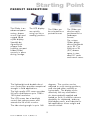
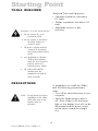
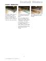
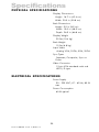
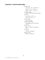
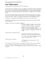
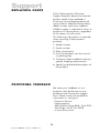
FIELD-READY FIELD-READY G L I D E R 20 User Manual ZZMicrosystems Microsystems Doc# 27-0006UM Issued 11/00 Rev 1.0 Regulatory FCC INFORMATION 1. Use the power and video cables supplied with the Glider to help prevent interference with radio and television reception. The use of cables and adapters may cause interference with electronic equipment in the vicinity of this unit. interference in when equipment is operated in commercial environments. This equipment generates, uses and can radiate radio frequency energy, and, if not installed and used in accordance with the instruction manual, may cause harmful interference to radio communications. 2. This equipment has been tested and found to comply with the limits for Class A digital devices, pursuant to certain limits imposed by Part 15 of the FCC rules. These limits are designed to provide reasonable protection against harmful 3. Operation of this equipment in a residential area is likely to cause interference in which case the user will be required to correct the interference at his own expense. Changes or modifications not expressly approved by Z Microsystems could void users authority to operate the equipment G L I D E R 20 2 Doc# 27-0006UM Issued 11/00 Rev 1.0 Contents STARTING POINT Shipment Contents User Manual System Requirements Product Description Tools Required Precautions 4 4 4 4 5 6 6 INSTALL RAILS Slide Removal Install The Slides In Cabinet Frame Install The Glider In Frame Installation Test Final Adjustments Install Cables 7 7 8 9 10 10 11 SETUP Setting Up Glider 12 12 PROTECTOR REMOVAL 14 OPERATION Connecting Cables Turn On Power 15 15 15 MONITOR ADJUSTMENTS Initial Setup And Adjustments Control Saving Settings Tips And Techniques 16 16 17 18 19 3 Doc# 27-0006UM Issued 11/00 Rev 1.0 DISPLAY HEAD REMOVAl 24 MAINTENANCE 25 DISPLAY STOWAGE Close Glider 26 26 TROUBLESHOOTING 28 SPECIFICATIONS Features Functional Specifications Physical Specifications Electrical Specifications Display Specifications 29 29 29 30 30 31 APPENDIX Y2K Compliance 32 32 SUPPORT Further Help Replacing Parts Providing Feedback 33 33 34 35 Starting Point Congratulations on selecting a rugged field-ready Glider -- the most advanced flat panel display available. SHIPMENT CONTENTS USER MANUAL The Glider shipping box contains the following: The User Manual comes in two formats: printed hardcopy or CDROM. This Manual is also available on the Z Microsystems website (www.zmicro.com). The Glider Unit Video Signal Cable AC/DC Power Supply with attached DC cable We recommend you read this manual as follows: AC Power Cable Carefully follow the instructions in the Installation chapter for hookup and initial control settings. Refer to the Operation chapter for a complete description of all the user controls, and the Maintenance chapter for care and correcting any unforeseen problems with the system. The Appendix is provided for quickly finding technical information about the Glider. User Manual Display Mount Unit Screen Protector Remember to save your original shipping container and packing material to transport or ship the Glider. SYSTEM REQUIREMENTS The Glider works with any computer system that provides industry standard screen formats from 640 x 480 to 1280 x 1024, with up to 75 Hz vertical sync. See the Specifications chapter of this Manual for a complete listing of all resolutions supported. The Glider requires a computer with a suitable onboard subsystem for Video Adapter Card that can support XGA 1024 x 768, SVGA 800 x 600, or VGA 640 x 480 at 60 Hz. 4 Doc# 27-0006UM Issued 11/00 Rev 1.0 Starting Point PRODUCT DESCRIPTION The Glider is an advanced spacesaving drawer mount high-end rugged liquid crystal display. The LCD display can quickly swing up into a reading position. The Glider can be oriented for a portrait format. The unique Glider design allows flat panels up to 20.1 to fold into a 2U (3.5) drawer space in standard 19 racks and transit cases. Specially designed quickrelease locks hold the compact folded Glider securely in place during storage. The lightweight and durable aluminum construction provides exceptional strength in field applications. degrees. The monitor can be adjusted to multi-viewing positions, and oriented either vertically or horizontally. The display works effectively with any workstation. The high quality LCD screen provides full color and features up to 1280 x 1024 pixel resolution. An electrostatically-applied and baked-on finish is used for extreme durability for shipboard, airborne, field deployments, and industrial or lab applications where weight and size are critical. The LCD screen has a backlight control that reduces power and extends the life of the monitor. The side-viewing angle is up to 160 5 Doc# 27-0006UM Issued 11/00 Rev 1.0 The Glider can also be easily positioned for a landscape format. Starting Point TOOLS REQUIRED Required Tools and Equipment. Flathead screwdriver with about 10" shaft. Phillips screwdriver with about 10" shaft. Adjustable wrench or box wrenches. WARNING: To avoid shock hazard: Do not remove the covers around the Glider. Do not connect or disconnect the Glider during an electrical storm. The power cord plug must be connected to a properly wired and grounded power outlet. Any equipment to which the Glider will be attached must also be connected to properly wired and grounded power outlets. The socket outlet shall be installed near the equipment and shall be easily accessible. PRECAUTIONS In preparation to install the Glider, take the following precautionary steps: Turn off the electrical power to your computer. NOTE: For the fastest and easiest installation of the Glider, follow these steps in the sequence they are presented. Verify the Glider power switch is off. If the Glider is off, the Power light on the display front will not be illuminated and the power switch will be down toward the straight line. 6 Doc# 27-0006UM Issued 11/00 Rev 1.0 Install Slides SLIDE REMOVAL With the Glider laid on a workbench, press down to release the ZLocks on each side of the front of the Glider to slide the side rails back. The slide rails will reach a stop about half way back. This is a safety stop to prevent the Glider from sliding out too far while mounted in the rack. Simultaneously press in the safety catches on each slide rail and slide the side rails all the way off the back of the Glider. 7 Doc# 27-0006UM Issued 11/00 Rev 1.0 The slides should now be separated from the Glider. Install Slides INSTALL THE SLIDES IN CABINET FRAME Each slide unit includes the slide rail, the front Z-Lock mount and the rear mount. The top notch of the ZLock must align with the slide rail top ridge. On the rear of the cabinet frame, use three Phillips screws to loosely secure the right and left rear slide mounts to the cabinet frame. DO NOT tighten these screws fully. As seen from this reverse view, align the slider into the Z-Lock bracket grooves so all three screw holes show. On the front of the cabinet frame, use three Phillips screws and washers per side to secure the right and left Z-Lock mounts holding the sliders. DO NOT tighten these screws to allow for adjustment of the Glider within the cabinet frame. On each slide rail, use a Phillips screwdriver to loosen the two adjustment screws toward the back of the slide rail. An adjustable wrench or box wrench may be used to hold the nut on the other side of the slide rail. 8 Doc# 27-0006UM Issued 11/00 Rev 1.0 At the back of the cabinest frame, tighten the slide mounts to the cabinet frame. Make sure to hold the slide mounts hard against the rack rail. Install Glider INSTALL THE GLIDER IN CABINET FRAME The Glider slides should move in and out easily. If not, check alignment of the slider and Z-Lock mount. Pull the two Glider slides out until they lock. Hold the Glider on each side over the back set of rollers, with the front into your stomach. The Glider MUST be level. This step may best be done with two people, one on each side of the slide rails. If the Glider binds during insertion, the Glider rollers are not properly aligned into the slider recepticle. Simultaneously press in the catches on each slider and move the Glider all the way into the cabinet frame. Feed the cables from the Glider back through the cabinet frame. Guide the Glider into the slides and slide the Glider in until it stops. 9 Doc# 27-0006UM Issued 11/00 Rev 1.0 If aligned properly, the rollers on the Glider slide smoothly into and out of the slider rails. Install Glider INSTALLATION TEST The Glider should easily close completely. Slide the Glider in and out several times. The Glider should slide in and out easily. Because of variances in cabinet frames, there may need to be some adjustments of the Glider slide system for best fit and movement of the Glider in and out. If the Glider binds when rolling in and out, perform the following procedures. FINAL ADJUSTMENTS Slide the Glider partially out. Use a flathead screwdriver to slightly move the Z-Locks in toward or out from the Glider, depnding on the need for best fit. While holding the Z-Locks at the proper setting, tighten the screws on the Z-Lock mounts. The Glider should slide in and out easily. If not, adjust the position of the two Z-Locks again. The Glider should now slide in and out smoothly. If not, repeat these steps. 10 Doc# 27-0006UM Issued 11/00 Rev 1.0 Go to the rear of the cabinet to tighten the slider extender rail scews. If there is not enough room to work at the back of the cabinet, the Glider may need to be removed to tighten the rail screws. INSTALL CABLES NOTE: The glider has an ACDC converter built into the power supply. Be sure the AC supply is 110 vac and properly grounded. WARNING: Be sure all electrical power to the cabinet is off before connecting any of the cables. WARNING: There is a key guide for alignment on the cables. Be sure the cable plug and receptacles are aligned properly using the key guide. Misalignment can cause short circuiting. The power supply is mounted on the back of the Glider tray. Be sure the power plug going in to the power supply is pushed all the way in. The power supply cable should be connected to a suitable 110-vac grounded power. The power cable comes out at the back of the power supply on the rear of the Glider tray. Be sure the plug is pushed all the way in. The socket outlet shall be installed near the equipment and shall be easily accessible. 11 Doc# 27-0006UM Issued 11/00 Rev 1.0 Setup SETTING UP GLIDER The outer Z-lock bracket fits snuggly against the female Z-lock bracket attached to the cabinet frame. With both hands, press both the Z-Locks down. Slide the Glider all the way out to the safety stop. Lift and slide the two display lock knobs at the back of the display to the open or inward positions. This allows the display top to be lifted from its storage position. Push down on the latch at the base of the display. Then lift the raised latch from its receptical to the unlatched position. Rotate the latch counterclockwise to unlock the latch. Holding the base with one hand, lift the back of the pivioted display up to the vertical position. VERY IMPORTANT. Once the display is locked in position, lower the latch back into the base recepticle. Hold the top of the display in the vertical position while rotating the latch clockwise to the locked position. 12 Doc# 27-0006UM Issued 11/00 Rev 1.0 SETTING UP GLIDER The display can be left in the vertical position or tilted back. The display can be rotated clockwise to angled positions. The Glider can be slid back until the back of the display almost touches the cabinet. 13 Doc# 27-0006UM Issued 11/00 Rev 1.0 The display can also be moved into the horizontal position. The control knobs will be on the bottom. Protector Removal The display protector is intended to protect the surface of the screen from damage while in transit or while stowed. The display protector is not intended to be used while the display is in operation. To remove the display protector, do the following: Rotate the display to the horizontal position, with the controls on the bottom. Move the display protector release button (located above the display) up. While holding up the display protector button, slide the protector to the right. 14 Doc# 27-0006UM Issued 11/00 Rev 1.0 Slide the protector off the edge of the display. To reinstall the display protector during long storage or shipping, just reverse this process. Operation CONNECTING CABLES NOTE: Connecting to non-standard systems will require an adapter. To obtain a video adapter, contact Customer Services at Z Microsystem, Inc. NOTE: Incorrect cable connections may result in irregular operation, damage display quality/components of the LCD module and/or shorten the modules life. Always consult the computer system manual. Verify the systems compatibility to ensure proper operation. NOTE: Make sure the DC connector is pluged in all the way on the back side of the display head. TURN ON POWER Turn on the Glider at the power switch on the back of the display. Off is when the straight line is down. On is when the circle is down. 15 Doc# 27-0006UM Issued 11/00 Rev 1.0 Monitor Adjustments INITIAL SETUP AND ADJUSTMENTS The Glider features pushbutton controls on the lower front of the display screen to adjust the brightness of the display, to change the image positioning on the screen, and to refine the screen image. To complete the setup of the Glider, use the following controls to fine tune the image on the screen: RESET Restores factory settings SELECT, H Pos, Adjusts image position horizontally SELECT, V Pos, Adjusts image position vertically SELECT, Clock, Adjustment of signal sampling point (left/right) SELECT, H Wd, Adjusts hortizontal size of image SELECT, Brt, Adjusts blacklight brightness 16 Doc# 27-0006UM Issued 11/00 Rev 1.0 Monitor Adjustments This section explains how to use the Glider control buttons to adjust the clarity of the display and image position on the screen. In particular it discusses: The function of each of the pushbutton controls. How to reset previously saved settings or return to factory settings. Tips and techniques. CONTROLS The Glider control buttons allow the user to control image position, clarity and backlight operations; and to store settings, and to revert to previously-saved or factory-saved settings. The controls to adjust the screen display are discussed in the next section. The controls to reset the settings are discussed in further detail in the section titled Saving Settings. RESET Restores the setting to the factory default. H Pos Moves the screen image to the left 17 Doc# 27-0006UM Issued 11/00 Rev 1.0 ( H Pos ) or to the right (H Pos ) Monitor Adjustments NOTE: The H Wd parameters must be properly set in order for the Clock settings to have their desired effect. The Clock settings are the final fine tuning adjustments. V Pos Moves the screen image up or down. Clock The Clock controls move the sampling points left or right while maintaining a fixed distance between samplings. These adjustments ensure that the sampling occurs at the peak of the input video signal (i.e. neither too early nor too late), thus eliminating any panel fuzziness or discoloration. When properly set, all vertical lines on the panel should look very crisp. H WD Increases or Decreases the horizontal screen size (width) by reducing or enlarging the sampling distance to synchronize the sampling frequency with the signal frequency. When properly set, no vertical banding will be noticeable. Brt Decreases or increases brightness of the backlight. SAVING SETTINGS NOTE: Cycling the power without the proper wait time will cause the last value change to be lost. The previous setting will be restored when power is returned. To save the screen settings for use in a future session, and through loss of power or video signal, allow 5 seconds to pass between the last adjustment and the time when power is restored to the system. The display will return with the values you had last set when the power is restored. 18 Doc# 27-0006UM Issued 11/00 Rev 1.0 The Glider can store screen settings for multiple resolutions, which is especially useful when it is used with a graphics card that supports a range of resolutions. The resolutions supported by the Glider include: 1280 x 1024, SXVGA 1024 x 768, XGA 832 x 624, Mac 800 x 600, SVGA 640 x 480, VGA 720 x 400, VGA Tet 640 x 400, PC9801 TIPS AND TECHNIQUES Graphics cards create a wide variety of screen resolutions. The Glider needs to be educated to interact properly with your systems graphics card. Once the Glider has been educated, the settings can be saved and the Glider will not need to be adjusted again, unless the graphics cards are changed. This section provides a thorough tutorial on adjusting the settings for the Glider. Unlike CRTs, flat panel displays do not require a high refresh rate for better display quality. In some cases, a high refresh rate may have a negative effect on display quality. If all display artifacts are not removed by the following procedure, try a lower vertical refresh rate setting on the computer systems graphics card. 19 Doc# 27-0006UM Issued 11/00 Rev 1.0 Monitor Adjustments Step 1: Power Up After the installation instructions have been followed: Turn on power to the computer/ workstation. Turn on power to the Glider. The Glider will then: Illuminate the Power indicator on the front panel. Perform self tests. Search for and automatically determine the frequencies and sync type of the incoming video signals. Illuminate the stby indicator on the front panel while powering up and searching for proper sync signals. Extinguish the Stby indicator on the front panel after acquiring proper sync signals. Display the video image on the screen. Step 2: If vertical adjustments are need on the screen display, press the SELECT button until the V Pos indicator is illuminated. Press either the button to raise the screen image or the button to lower the screen image. In most cases, the image can be adjusted precisely to center. NOTE: A black band at the top and bottom of the display may be visible at certain resolutions. This is normal, as the expanded screen in some resolutions does not precisely fit the Glider screen dimensions. 20 Doc# 27-0006UM Issued 11/00 Rev 1.0 Adjust Vertical Position Monitor Adjustments Step 3: Width Adjust Horizontal This is the critical step to ensure a crisp screen image. For a Sharp display, you must adjust the image so that it fits precisely within the boundaries of the screen. To adjust the horizontal width: 1. Press the SELECT button until the H Wd indicator is illuminated. Alternately press the and buttons to size the screen image to the exact width of the display. Adjusting so that there are no borders on either side of the display may aid in this process. 2. As you approach the proper horizontal setting, fuzzy vertical ghosting bands will appear on the screen. These can be very subtle, depending on the image being displayed. 3. As you continue to make horizontal width adjustments, these bands will become wider and wider until the entire screen becomes fuzzy all over (i.e., no vertical bands), or crisp all over. Helpful Hint: A uniformly fuzzy screen is often the last step before locking on to the best screen image. 21 Doc# 27-0006UM Issued 11/00 Rev 1.0 Monitor Adjustments Step 4: Adjust Horizontal Po s i t i o n Press the SELECT button until the H Pos indicator is illuminated, then use the and buttons to adjust the horizontal position of the screen left or right to center the screen image. Helpfut Hint: When the screen is properly adjusted, the left and right sides of the screen will line up precisely with the left and right sides of the panel. A single push of the button should cause a very narrow band (one or two pixels wide) to appear on the left side of the screen. Similarly, a single push of the button should cause a very narrow band (one or two pixels wide) to appear on the right side of the screen. Step 5: Adjust Clock Once the appropriate adjustments have been made, press the SELECT button until the Clock indicator is illuminated, then use the and buttons to obtain a crisp screen. 22 Doc# 27-0006UM Issued 11/00 Rev 1.0 To adjust the screen for the best possible display, try the following: Press the and buttons until you have a universally fuzzy screen. Count the number of button presses for the screen to go from fuzzy to clear to fuzzy again. NOTE: If at this point the screen image is not crisp, repeat Steps 2-4. Divide the number of presses by two and press the button that many times to precisely end up at the clearest setting. The clearest setting may also be verified by visually monitoring the screen while adjusting the settings. Step 6: Adjust Brightness If the brightness adjustment is made to maximize the display visibility, press the SELECT button until the Brt indicator is illuminated, then use the and buttons to increase/ decrease the display brightness. The factory default setting is maximum brightness. NOTE: See Saving Settings earlier in this manual for a complete discussion of this subject. Step 7: 23 Doc# 27-0006UM Issued 11/00 Rev 1.0 Saving Adjustments The screen settings will automatically be saved as long as the power is maintained for at least five seconds after the last adjustment. Display Head Removal WARNING: Be sure all electrical power is turned off to the Glider before proceeding. To remove the Glider display head, follow these steps: Rotate the display to the horizontal position. On the back of the display, disconnect the power cable. Disconnect the video cable next to the power cable. On the back of the display, press the mounting arm button to release the display head locking bar. Swing the display locking bar out. Use two hands to lift the display up out of the rack mount. Be careful that the power and video cables do not catch on anything. The display is now removed from the head mount. 24 Doc# 27-0006UM Issued 11/00 Rev 1.0 CLEAN MONITOR WARNING: Be sure to turn off the power before performing any maintenance on the monitor. WARNING: To avoid risk of electric shock, DO NOT dissemble the monitor cabinet. User maintenance is restricted to cleaning as explained here. Gently wipe the covers and the screen with a soft cloth. Remove finger marks and grease with a damp cloth and mild detergent. DO NOT use solvents or abrasives. Never use flammable cleaning material to clean the monitor or other ectrical apparatus. 25 Doc# 27-0006UM Issued 11/00 Rev 1.0 Display Stowage CLOSE GLIDER The following describes closing and stowage of the Glider in the cabinet. Pull the Glider all the way out to the stop. Tilt the display head back. From the landscape position, rotate the display to the vertical position. Make sure there is enough room to lower the top of the display head without hitting the cabinet. VERY IMPORTANT Rotate the display pivot latch counter-clockwise to release the side lock linkage. Tilt the display head back towards the rear of the rack all the way to the horizontal position. Rotate the display latch clockwise to engage the side lock linkage. The display latch has now locked the side linkage. Hold the top of the display while rotating the pivot latch. Lift up the display pivot latch. Lower the display into the Glider frame tray. 26 Doc# 27-0006UM Issued 11/00 Rev 1.0 Display Stowage CLOSE GLIDER Lower the pivot latch into its recepticle. Slide the two display linkage locks at the back of the display to the closed position to secure the display. 27 Doc# 27-0006UM Issued 11/00 Rev 1.0 Slide the Glider into the frame until it snaps into the closed, secure position. Troubleshooting NO IMAGE ON DISPLAY Flip the power switch to on. The circle should be down. Connect the power cable to a 110 vac outlet, which is turned on. Connect the video cable to the computer. Be sure the computer is on and operating. Make sure the power cable to the back of the Glider is plugged in all the way. Make sure the video cable to the back of the Glider is plugged in all the way. Make sure the power cable from the Glider to the back of the display head is plugged in all the way. Make sure the video cable from the Glider to the back of the display head is plugged in all the way. 28 Doc# 27-0006UM Issued 11/00 Rev 1.0 FEATURES Large Display Area Multi-Scan/Sync Capability Wide Viewing Angle Small Package Outline Full Color High Contrast Ratio FUNCTIONAL SPECIFICATIONS Supported Resolutions 640 x 400* 720 x 400* (text) 640 x 480 800 x 600* 832 x 624* 1024 x 768* 1280 x 1024 * Interpolated Resolutions: When resolutions are shown that are lower than the pixel count of the LCD module, text may appear choppy or lines may appear to be bold. This is normal and necessary for all current flat panel technologies when displaying non-native resolutions full screen. In flat panel technology, each dot on the screen is actually one pixel, so to expand resolutions to full screen, an interpolation of the resolution must be done. When the interpolated resolution is not an exact multiple of the native resolution, the mathematical interpolation necessary may cause some lines to appear thicker than others. 29 Doc# 27-0006UM Issued 11/00 Rev 1.0 Specifications PHYSICAL SPECIFICATIONS Display Dimensions Height 16.7 in (42.4 cm) Width 20.0 in (50.8 cm) Rack Dimensions Height 3.5 in (8.9 cm) Width 19.0 in (48.3 cm) Depth 26.3 in (66.8 cm) Display Weight 23 lbs (10.4 kg) Rack Weight 15 lbs (6.8 kg) Input Video Analog VGA, SVGA, XGA, SXGA Sync Types Separate, Composite, Sync on Green Video Connector 15-pin VGA standard male sub HD15, D-type ELECTRICAL SPECIFICATIONS Power Supply 90 - 250 VAC; 47 - 63 Hz; 80 W max Power Consumption 60 W typical 30 Doc# 27-0006UM Issued 11/00 Rev 1.0 DISPLAY SPECIFICATIONS Display Area Horizontal 15.7 in (39.9 cm) Vertical 12.6 in (32.0 cm) Diagonal 20.1 in (50 cm) Number of Pixels 1280 x 1024, RGB Vertical Stripe Pixel Pitch Horizontal 0.312 mm Vertical 0.312 mm Contrast Ratio 150:1 (typical) Total Viewing Angle 160 degrees (horizontal and vertical) Response Time 130 ms (maximum) black to white Luminance 150 cd/m2 (typical) Display Colors Full-color (millions) 31 Doc# 27-0006UM Issued 11/00 Rev 1.0 Appendix Y2K COMPLIANCE Z Microsystems has achieved full Y2K Compliance. In late 1997, the companys senior management assigned a Y2K Project Team that consists of a cross-functional representation from information technology, procurement, manufacturing, test and development, finance, general affairs, engineering, marketing and facilities organizations to address the Year 2000 issues. The Assessment/Rectification Phase of the Year 2000 efforts and full compliance for all mission critical internal systems were accomplished as scheduled by the end of Q1, 1999. Contingency development and validation of the companys overall Year 2000 readiness will continue through 1999. The following strategically important categories have been assessed for Year 2000 readiness: Suppliers and Service Providers Readiness. All major strategic suppliers are assessed to be Year 2000 compliant. Most of the companys service providers compliance efforts will continue through 1999. Major concerns and efforts will be focused on the companys shipping companies in 1999. Z Microsystems Internal Systems Z Microsystems Products All mission critical internal systems are determined to be fully Year 2000 Compliant. A few minor Year 2000 related issues need to be addressed in 1999. All Z Microsystems products are in full compliance. The companys MIS has taken the lead and worked with the Finance Department to develop comprehensive Year 2000 Contingency Plans for the companys mission critical application systems to assure the continuity of daily business. 32 Doc# 27-0006UM Issued 11/00 Rev 1.0 Support FURTHER HELP If you are unable to correct any problem yourself, contact: Z Microsystems at: (858) 657-1000 Fax: (858) 657-1001 Website: www.zmicro.com Before calling, please have available as much of the following information as possible: 1. Model and serial number from the label on the monitor. 2. Purchase Order number. 3. Description of problem. 4. Computer type and model. NOTE: If possible, stay by the computer. The Z Microsystems Technical Support Representative may wish to go through the problem over the telephone. 5. System configuration (hardware fitted, etc.). 6. System BIOS version number. 7. Operating System and version number. 8. Display driver version number. 9. Video Adapter type. NOTE: More help, late-breaking news and details of the latest accessories for these products may be found on the worldwide web at: http:// www.zmicro.com 33 Doc# 27-0006UM Issued 11/00 Rev 1.0 Support REPLACING PARTS If the Z Microsystems Technical Support Engineer determines that the product needs to be replaced, a Customer Service Representative will issue a Return Material Authorization (RMA) number and return address. A RMA number is required to return a product to Z Microsystems, regardless of the reason for the return. The following information is required when returning Z Microsystems products: 1. Model number 2. Serial number 3. Date of purchase 4. Proof of purchase (use the invoice or packing slip) 5. Customer ship-to address and any special shipping requirements 6. Specific and detailed description of the problem PROVIDING FEEDBACK We value your feedback on our products, their performance, any problems and constructive suggestions. Please send such productive information in writing to: Customer Service Z Microsystems 5945 Pacific Center Blvd., Suite 509 San Diego, CA 92121-4309 or www.zmicro.com 34 Doc# 27-0006UM Issued 11/00 Rev 1.0 Z Microsystems, Inc. 5945 Pacific Center Blvd., Suite 509 San Diego, CA 92121 Phone: (858) 657-1000 Fax; (858) 657-1001 Website: www.zmicro.com Copyright 1999 Z Microsystems, Inc. All Rights Reserved Doc# 27-0006UM Issued 11/00 Rev 1.0