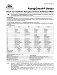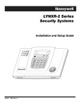
1
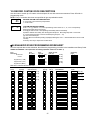
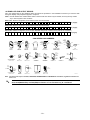
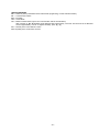
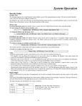
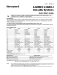
/<1;56HULHV
6HFXULW\6\VWHPV
3URJUDPPLQJ*XLGHIRU
/<1;5/<1;5DQG/<1;5(1
OFF
AWAY
STAY
AUX
®
®
K5965 5/01 Rev. B
7$%/(2)&217(176
DATA FIELDS ............................................................................................................................................................................3
*56 ENHANCED ZONE PROGRAMMING ...............................................................................................................................11
*80 DEVICE PROGRAMMING .................................................................................................................................................13
*81 ZONE LISTS ......................................................................................................................................................................14
*83 ENHANCED SEQUENTIAL MODE ...................................................................................................................................15
*84 ASSIGN ZONE VOICE DESCRIPTORS............................................................................................................................16
VOCABULARY INDEX (for *84 Assign Zone Voice Descriptors).............................................................................................16
*85 RECORD CUSTOM VOICE DESCRIPTORS ....................................................................................................................17
*56 ENHANCED ZONE PROGRAMMING WORKSHEET .......................................................................................................17
POWERLINE CARRIER DEVICE WORKSHEET FOR *80 and *81........................................................................................19
5800 SERIES TRANSMITTER LOOP DESIGNATIONS DIAGRAM.........................................................................................20
SPECIAL MESSAGES .............................................................................................................................................................21
LYNXR Series SUMMARY OF CONNECTIONS DIAGRAM ....................................................................................................22
Refer to the Installation and Setup Guide for detailed information on programming the LYNXR/LYNXR24 or
LYNXR-EN system. The Installation and Setup Guide includes full descriptions of all data fields.
8/
LYNXR and LYNXR-EN are not intended for UL985 Household Fire applications unless a 24-hour
backup battery (P/N LYNXRCHKIT-HC) is installed.
!
Certain features differ between the LYNXR/LYNXR24 and the LYNXR-EN models. Verify the specific
model being installed prior to the system programming.
TO ENTER PROGRAMMING MODE:
1. Power up, then depress [✱] and [#] both at once, within 50 seconds of powering up.
OR
2. For factory defaulted system, enter: Installer Code (4 + 1 + 1 + 2) plus 8 + 0 + 0. OR
If different Installer Code is programmed, enter: New Installer Code + 8 + 0 + 0.
(if ✱98 was used to exit previously, method 1 above must be used to enter the program mode again)
3. Upon entry into Program mode, data field *20 will be displayed (the first data filed in the system) and both
keypad LEDs will flash.
TO PROGRAM THE DATA FIELDS:
1. Press [*] followed by the desired field number (e.g., *21), then make the required entry.
2. The keypad beeps three times after entering data, then displays the next data field in sequence.
3. For phone number and account number fields, press [*] to end the entry if less than number maximum
number of digits is entered.
4. To delete an entry, simply press [*] plus that field number and reenter the correct data. For phone
number and account number fields *40-*44, *88 and *94, press [*] + field number + [*].
INTERACTIVE MENU MODES:
There are six interactive menu modes as listed below. To enter these modes, first enter Program mode. While
in Program mode, press [*] plus the mode number desired (e.g., *56).
*56 Enhanced Zone Programming .............For programming zone characteristics, report codes, etc.
*80 Device Programming............................For programming Powerline Carrier Devices
*81 Zone List Programming ........................For programming zone lists for use with Powerline Carrier Devices
*83 Enhanced Sequential Mode .................For entering transmitter serial numbers
*84 Assign Zone Voice Descriptors ............For assigning voice descriptors to zones
*85 Record Custom Voice Descriptors .......For recording custom voice descriptors
-2-
TO LOAD A DEFAULT SET:
While in Program mode, press *97, then enter a number 1-4 corresponding to the default table desired. See the
Installation Instructions for the default tables. Enter 0 if you are not selecting a default table.
TO EXIT PROGRAMMING MODE:
✱98 Exits programming mode and prevents re-entry by: Installer Code + 8+ 0 + 0. If ✱98 is used to exit
programming mode, system must be powered down, then press [*] and [#] within 50 seconds of power
up to re-enter programming mode.
✱99 Exits programming mode and allows re-entry by: Installer Code + 8 + 0 + 0 or: Power-up, then press [*]
and [#] within 50 seconds of power up.
DATA FIELDS
Field
Function
Programmed Values
[ ] = Table 1 Default Values
SYSTEM SETUP (✱ 20– ✱ 30)
✱20
INSTALLER CODE
[4112]
Enter 4 digits, 0–9
✱21
QUICK ARM ENABLE
†
[1]
0 = no; 1 = yes
✱22
KEYPAD BACKLIGHT TIMEOUT
[0]
0 = none (backlighting always on); 1 = backlight off after 10secs
✱23
FORCED BYPASS
†
[0]
0 = none; 1 = bypass open zones
UL installations = 0
✱24
RF HOUSE ID CODE
|
[00]
00 = disable all wireless keypad usage;
01–31 = 5827/5804BD/5804BDV house ID
✱25
✱26
POWERLINE CARRIER DEVICE
HOUSE CODE
CHIME BY ZONE
[0]
0 = A; 1 = B, 2 = C, 3 = D, 4 = E, 5 = F, 6 = G, 7 = H, 8 = I,
9 = J, #10 = K, #11 = L, #12 = M, #13 = N, #14 = O, #15 = P
† [0]
0 = no; 1 = yes (program zones to chime on zone list 3)
✱27
REAL TIME CLOCK DISPLAY
† [1]
0 = no; 1 = yes, display time on keypad
✱29
✱30
DAYLIGHT SAVING TIME
START/END MONTH
DAYLIGHT SAVING TIME
START/END WEEKEND
[4, 10]
Start
End
1-9, #+10,#+11,#+12. Enter 0,0 if no daylight savings time used.
[1,5]
Start
End
0=disable; 1=first; 2=second; 3=third; 4=fourth;
5=last; 6=next to last; 7=third from last
-3-
Field
Function
Programmed Values
ZONE SOUNDS AND TIMING (✱ 31– ✱ 39)
SINGLE ALARM SOUNDING/ZONE
✱31
[ ] = Table 1 Default Values
† [0]
1 = yes, limit once per arming period (also applies to long range radio
output if “0” is selected in *91 field); 0 = no limit
UL installations = 0
✱32
FIRE SOUNDER TIMEOUT
✱33
ALARM BELL TIMEOUT
† [0]
0=timeout; 1=no timeout
† [1]
0 = none; 1=4 min; 2=8 min; 3=12 min; 4 = 16 min
UL installations = 1 (4 min) minimum
✱34
EXIT DELAY
† [70]
|
00-99 = exit delay time (in seconds).
UL installations = 60 seconds max.
✱35
ENTRY DELAY 1 (zone type 01)
† [30]
|
00-99 = entry delay time (in seconds);
UL installations = 45 seconds max.
✱36
ENTRY DELAY 2 (zone type 02)
† [60]
|
00-99 = entry delay 2 time (in seconds);
UL installations = 45 seconds max.
✱37
AUDIBLE EXIT WARNING /
QUICK EXIT
† [1, 1]
Exit Warn Quick Exit
0 = no; 1 = yes
✱38
CONFIRMATION OF ARMING DING
† [0]
0 = no; 1 = yes (when armed by self-contained keypad or RF)
2 = yes (when armed by RF keypad only).
✱39
POWER UP IN PREVIOUS STATE
† [1]
0 = no; 1 = yes; UL installations = 1
† Entering a number other than the one specified may give unpredictable results.
DIALER PROGRAMMING (✱ 40– ✱ 53)
In fields ✱40, ✱41, ✱42, enter up to the number of digits shown. Do not fill unused spaces. Enter 0–9; #+11 for '*';
#+12 for '#'; #+13 for a pause.
PABX ACCESS CODE
✱40
Enter 6 digits. If fewer than 6 digits are entered, pressing *
advances to the next field. To clear entries from field, press *40*
✱41
PRIMARY PHONE NUMBER
Enter up to 20 digits; Do not fill unused spaces. If fewer than 20 digits
entered, pressing * advances to the next field. To clear entries from
field, press * 41* .
-4-
Field Function
✱42
Programmed Values
[
] = Table 1 Default Value
SECONDARY PHONE NUMBER
Enter up to 24 digits; Do not fill unused spaces. If fewer than 24 digits
entered, pressing * advances to the next field. To clear entries from
field, press *42* .
For fields *43 , *44:
Enter 0–9; #+11 for B; #+12 for C; #+13 for D; #+14 for E; [#+15 for F]. Enter ✱ as 4th digit, if 3+1 dialer reporting is to be
used. If only 3 digits used, pressing ✱ advances to the next field.
To clear entries from field, press ✱43✱ or ✱44✱ .Examples:
For Acct. 1234, enter:
1 | 2 | 3 | 4
For Acct. 123, enter:
1 | 2 | 3 | ✱
; For Acct. B234, enter: #+11| 2 | 3 | 4
✱43
PRIMARY SUBS ACCT #
[15, 15, 15, 15]
✱44
SECONDARY SUBS ACCT #
See note on previous page
✱47
PHONE SYSTEM SELECT
† [1] (LYNXR/LYNXR24)
Note: If you are using Pulse
(rotary) Dialing, make sure
that LYNX has finished
dialing the last number you
dialed (listen to pulses)
† [5] (LYNXR-EN)
For LYNXR/LYNXR24 only options 0, 1, 2, and 3 are applicable
Central
Station
No WATS
WATS
✱48
REPORT FORMAT for PRIM./SEC
Dialing Mode
Pulse
0 = No Speaker
Phone
2 = No Speaker
Phone
[7, 0]
Primary Secondary
Tone
Tone
5 = With
Speaker Phone
7 = With
Speaker Phone
Note: Option 7 (ADEMCO Contact ID®) must
be selected for AVM.
0 = 3+1, 4+1 ADEMCO L/S STANDARD
1 = 3+1, 4+1 RADIONICS STANDARD
2 = 4+2 ADEMCO L/S STANDARD
3 = 4+2 RADIONICS STANDARD
6 or undefined = 4+2 ADEMCO EXPRESS
7 = ADEMCO CONTACT ID REPORTING
8 = 3+1, 4+1 ADEMCO L/S EXPANDED
9 = 3+1, 4+1 RADIONICS EXPANDED
† Entering a number other than the one specified may give unpredictable results.
-5-
Pulse
1 = No Speaker 4 = With
Phone
Speaker Phone
3 = No Speaker 6 = With
Phone
Speaker Phone
Field
Function
✱49
SPLIT/DUAL REPORTING
** Pager Message
A 7-digit code (plus optional 16-digit prefix) is
sent to the pager consisting of a 3-digit event code,
followed by 00 and a 2-digit user or zone number.
See Installation Instructions for an explanation of
the pager code, which takes the following form:
AAAAAAAAAAAAAAAA-EEE-00NN
Programmed Values
15 SEC DIALER DELAY (BURG)
✱51
PERIODIC TEST REPORT
] = Table 1 Default Value
[0]
0 = Disable (Backup report only)
TO PRIMARY PHONE No.
1 = Alarms, Restore, Cancel
2 = All except Open/Close, Test
3 = Alarms, Restore, Cancel
4 = All except Open/Close, Test
5 = All
TO PRIMARY PHONE No.
6 = All except Open/Close
7 = All reports
8 = All reports
9 = All except Open/Close
TO SECONDARY PHONE No.
Others
Open/Close, Test
All
All
All
TO PAGING** No. (Secondary)
Alarms, Open/Close‡, Troubles
Alarms, Troubles
Alarms, Open/Close‡, Troubles
Open/Close‡
‡ Will report users 0, 5-8 or wireless
arm/disarm button zones 26-33; all other
zones and users do not report
AAA… = optional 16-digits (see field *88)
EEE = 3-digit event code: 911 (alarm), 101 (open), 102 (close),
811 (trouble)
00
= always displayed
NN
= 2-digit user number or zone number depending on type
of event (EEE) that occurred.
✱50
[
† [0]
0 = no; 1 = yes; UL installations = 0
† [0]
0 = none; 1 = 24 hours; 2 = weekly; 3 = 30 days
(enter Test Code in field *64)
✱52
FIRST TEST REPORT OFFSET
† [2]
0 = 24 hour; 1 = 6 hours; 2 = 12 hours; 3 = 18 hours
(Time to 1st report from power up/programming or downloading).
✱53
SESCOA/RADIONICS SELECT
[0]
0 = Radionics (0–9, B–F reporting); 1 = SESCOA (0–9 only reporting).
Select 0 for all other formats.
✱56
✱58
ENHANCED ZONE
PROGRAMMING
RF JAM DETECT
See procedure in this form and refer to the Installation Guide.
[0]
0 = no RF Jam Detection; 1 = RF Jam Detect on, no CS report;
2 = RF Jam Detect on with CS report
(if trouble/restore report is enabled in fields *60, *71)
Notes: (1)
(2)
This feature cannot be used in conjunction with the 5827 wireless
keypad.
For event logging option 2 must be selected.
† Entering a number other than the one specified may give unpredictable results.
-6-
Field
Function
Programmed Values
[
] = Table 1 Default Value
TO PROGRAM SYSTEM STATUS, & RESTORE REPORT CODES (✱59–✱76, & ✱89):
With a 3+1 or 4+1 Standard Format: Enter a code in the first box: 1–9, 0, B, C, D, E, or F. Enter "#+10" for 0, "#+11" for B,
"#+12" for C, "#+13" for D, "#+14" for E, "#+15" for F.
A "0" (not "#+10") in the first box will disable a report.
A "0" (not "#+10") in the second box will result in automatic advance to the next field when programming.
With an Expanded or 4+2 Format: Enter codes in both boxes (1st and 2nd digits) for 1–9, 0, or B–F, as described above.
A "0" (not "#+10") in the second box will eliminate the expanded message for that report.
A "0" (not "#+10") in both boxes will disable the report.
With Ademco Contact ID Reporting: Enter any digit (other than "0") in the first box, to enable zone to report (entries in the
second boxes will be ignored).
A "0" (not "#+10") in the first box will disable the report.
Examples:
For Code 3 (single digit), enter:
3 | 0
For Code 3 2 (two digits), enter:
3 | 2
For Code B 2 (Hexadecimal), enter:
#+11 | 2
SYSTEM STATUS REPORT CODES (*59–*68)
✱59
EXIT ERROR REPORT CODE
[1] 2nd digit is automatically sent as 2nd digit of the zone alarm report
code programmed in *56, if expanded or 4+2 reporting is selected.
✱60
TROUBLE REPORT CODE
|
[1,0]
✱61
BYPASS REPORT CODE
|
[0,0]
✱62
AC LOSS REPORT CODE
|
[0,0]
✱63
LOW BAT REPORT CODE
|
[1,0]
✱64
TEST REPORT CODE
|
[1,0]
✱65
OPEN REPORT CODE
✱66
ARM AWAY/STAY RPT CODE
†† [0]
(†† 2nd digit is automatically sent as the user
†† [0,0]
AWAY
number if expanded or 4+2 reporting is
selected.)
STAY
† Entering a number other than the one specified may give unpredictable results.
✱67
RF XMTR LOW BAT REPORT CODE
|
[1,0]
✱68
CANCEL REPORT CODE
|
[1,0]
RESTORE REPORT CODES (*70–*76)
ALARM RESTORE RPT CODE
✱70
[1] 2nd digit is automatically sent as 2nd digit of the zone alarm report
code programmed in *56, if expanded or 4+2 reporting is selected.
✱71
TROUBLE RESTORE RPT CODE
|
[1,0]
✱72
BYPASS RESTORE RPT CODE
|
[0,0]
✱73
AC RESTORE RPT CODE
|
[0,0]
✱74
LOW BAT RESTORE RPT CODE
|
[1,0]
Field
Function
Programmed Values[
-7-
] = Table 1 Default Value
✱75
RF XMTR LO BAT RST RPT CODE
|
[1,0]
✱76
TEST RESTORE RPT CODE
|
[0,0]
OUTPUT AND SYSTEM SETUP (*80–*92)
DEVICE PROGRAMMING MENU
✱80
MODE
ZONE LISTS MENU MODE
✱81
ENHANCED SEQUENTIAL MODE
✱83
See procedure later in this manual.
✱84
ASSIGN ZONE VOICE
DESCRIPTOR
See procedure later in this manual.
✱85
RECORD CUSTOM VOICE
DESCRIPTOR
See procedure later in this manual.
✱87
AUX FUNCTION/ 1-BUTTON
PAGING
Program *80 and *81 only if Powerline Carrier Devices or chime
by zone are to be used. See procedure later in this manual.
[0]
0 = Aux key performs defined function (macro);
1 = Aux key sends message (999-9999) to pager
If 1, you must also select an option 6-9 in field *49.
✱88
PAGER CHARACTERS
Up to 16 digits can be entered that will appear in front of the 7-digit
pager message sent by the control (either upon system event or upon
pressing AUX key [if programmed for paging]; see field *87 and *49 for
other options regarding the paging feature). See the Installation
Instructions (fields *87, *88 and *49) for full descriptions of the paging
feature. You do not need to fill all 16 digits (press [*] to advance to
next field). To clear entries, enter *88*.
To enter “*” = [#] + [11]; To enter “#” = [#] + 12]
To enter 2-second pause = [#] + [13] (some pagers require an
additional delay [pause] in order to receive the entire message)
✱89
EVENT LOG 80% FULL RPT CODE
✱90
EVENT LOGGING
[0,0]
|
[3]
0 = None; 1 = Alarm/Alarm Restore; 2 = Trouble/Trouble Restore;
4 = Bypass/Bypass Restore; 8 = Open/Close.
Example: To select “Alarm/Alarm Restore”, and “Open/Close”, enter 9
(1 + 8); To select all, enter #15.
Note: System messages are logged when any non-zero selection is made.
-8-
Field
✱91
Function
LYNXR/LYNXR24
LONG RANGE RADIO/ALARM
AUDIO VERIFICATION
(AAV)/REMOTE PHONE CONTROL
Programmed Values[
] = Table 1 Default Value
[2]
0 = Long range radio only
1 = AAV and remote phone control
2 = Long range radio and remote phone control
4 = AAV only
Notes: (1) If long range radio is being connected alarm audio verification cannot be
used.
(2) In order to activate the remote phone access feature and defeat an
answering machine ensure that the correct ring detection count (“15”)
has been programmed in field *95.
(3) Remote phone session will be terminated if a report must be sent.
(4) If alarm audio verification mode is selected a long range radio cannot be
connected.
(5) Alarm audio verification will only function when Contact ID is selected
and cannot be used for UL installations.
(6) If an alarm will be reported to primary and secondary phone numbers,
AAV can only function via the secondary number.
(7) If an alarm will be reported to a pager (6, 7, or 8 in field *49), AAV
cannot be used.
LYNXR-EN
ALARM AUDIO VERIFICATION
(AAV)/REMOTE PHONE CONTROL
[2]
0 = None
1 = AAV and remote phone control
2 = remote phone control only
4 = AAV only
Notes: (1) No programming is required if connecting an ALARMNET 7845C device
because the option is always enabled.
(2) In order to activate the remote phone access feature and defeat an
answering machine ensure that the correct ring detection count (“15”)
has been programmed in field *95.
(3) Remote phone session will be terminated if a report must be sent.
(4) Alarm audio verification will only function when Contact ID is selected
and cannot be used for UL installations.
(5) If an alarm will be reported to primary and secondary phone numbers,
AAV can only function via the secondary number.
(6) If an alarm will be reported to a pager (6, 7, or 8 in field *49), AAV
cannot be used.
✱92
NUMBER OF REPORTS IN ARMED
PERIOD
[0]
0 = 10 Alarm/Alarm Restore Reports;
1 = Unlimited (UL installations = 0)
DOWNLOAD INFORMATION (*93,*94,*95)
FLEXIBLE CALLBACK
✱93
[0]
0 = No flexible callback; 1 = Last digit flexible; 2 = Last 2 digits flexible;
3 = Last 3 digits flexible
✱94
DOWNLOAD PHONE NUMBER
Enter up to 20 digits, 0–9; #+11 for '✱'; #+12 for '#'; #+13 for a pause.
Do not fill unused spaces. If fewer than 20 digits entered, pressing ✱
advances to the next field. To clear entries from field, press ✱94✱.
Note:
In UL installations, downloading may only be performed if a technician
is at the site.
-9-
Field
Function
✱95
RING DETECT COUNT FOR
DOWNLOADING/REMOTE PHONE
CONTROL MODE
Programmed Values
[
] = Table 1 Default Value
[15]
0 = Disable Station Initiated Download; 1–14 = number of rings (1–9,
[#]+10 =10, [#] +11 =11, [#] +12 =12, [#] +13 =13, [#] +14 =14);
15 = answering machine defeat ([#] +15 =15)
✱96
INITIALIZE DOWNLOAD ID &
SUBSCRIBER ACCOUNT
No entry required
✱97
SET ALL PROGRAM FIELDS TO
1 OF 4 SETS OF DEFAULT VALUES
Enter 1-4 to select from default tables 1-4
Enter 0 to abort.
✱98
EXITS PROGRAMMING MODE
(PREVENTS RE-ENTRY)
Installer Code + 8+ 0 + 0.
If ✱98 is used to exit programming mode, you must press "✱" and "#" within 50
seconds of power up or from exiting Programming mode to re-enter
Programming mode.
After exiting Program mode, the system takes up to 1 minute to
Note:
reset. To bypass the reset delay, press [#] + [0].
✱99
EXITS PROGRAMMING MODE
(ALLOWS RE-ENTRY)
Installer Code + 8 + 0 + 0 or:
Power-up, then press "✱" and "#" within 50 seconds of power
up or from exiting Programming mode.
Note:
After exiting Program mode, the system takes up to 1 minute to reset.
To bypass the reset delay, press [#] + [0].
- 10 -
*56 ENHANCED ZONE PROGRAMMING PROCEDURE
Use this mode to program zone information. Press *56 while in programming mode.
Notes: (1) Entering a number other than the one specified may give unpredictable results.
(2) You may find it convenient to adjust the volume setting before entering the Programming Mode. This will allow
you to clearly hear feedback announcements or system beeps.
%
-
b
zt
'
rc
d
i
)
l
ZONE NUMBER
Enter the 2-digit zone number to be programmed.
selected zone, if it is programmed.
[*] = Continue
00 = exit zone programming mode;
upon exiting, the prompt “56” blinks; press
[*] + any field number to go to that field.
The system will announce the Voice Descriptor for the
• Zone 1 = hard wire zone
• Zones 2-25 = RF transmitter zones (only)
• Zone 26-41 = RF button zones (only)
• Zone 92 = Duress
• Zone 95, 96, 99 = Panic zones
ZONE TYPE
Enter the 2-digit zone type (zt) for this zone (see table of zone types on worksheet page 13).
[*] = Continue [if 00 is entered the system will skip to DELETE ZONE PARAMETERS prompt (F)].
[#] = Return to previous prompt
REPORT CODE
Enter the report code (rc) for this zone.
Report consists of 2 hexadecimal digits, each composed of 2 numerical digits (A = 10, B = 11, C = 12, D
= 13, E = 14, F = 15; see Report Code description on page 6 for explanation of codes).
[*] = Continue; If this is zone 1, 95, 96 or 99, the system skips to the VOICE DESCRIPTOR prompt (1C)
[#] = Return to previous prompt
INPUT TYPE
Enter the input type (i) for the transmitter assigned to this zone as follows:
3 = Supervised RF (RF)
[*] = Continue
4 = Unsupervised RF (UR)
[#] = Return to previous prompt
5 = Button type (BR)
Note
Zones 2-25 should be assigned
as Input Type 3 or 4 and Zones
26-41 should be assigned as
LOOP NUMBER or LOOP AND SERIAL NUMBER (if using RF Learning)
Note: It is not necessary to manually enter a Loop Number if using the RF Learning Mode.
RF Learning - Two (2) transmissions (two key depressions at least five seconds apart) will be required
for BR type devices (device type 5). Two beeps will sound after the second transmission, confirming that
the loop number and serial number have been learned.
For all other device types, four (4) transmissions are required (fault, restore and fault, restore). A single
beep will sound after the second transmission confirming that the loop and serial number have been
captured. Following the fourth transmission the system will confirm that the loop and serial number have
been learned by announcing the Voice Descriptor for the zone, if it is programmed, followed by two
beeps.
Note: BR type devices cannot be enrolled by using UR or RF type. Likewise, UR or RF type devices cannot be
enrolled by using a BR type device. There is a 52-second time-out for RF enrolling. At the end of the time-out,
the system returns to the INPUT TYPE prompt (d). If enrolled, loop number and “L” are displayed.
Manual Entry - Enter the desired loop number and press[*] to continue (see the transmitter’s Installation
Instructions for specific loop designations). If “L” is displayed the zone’s serial number has already been
enrolled.
Note: The loop number can be changed even if the zone has already been entered. Care should be taken when using
this feature as it has the capability to make zones inoperable by creating a mismatch of a working serial
number/loop number combination. This should be re-confirmed if the loop number is changed.
0 + [*] = to Delete Serial Number prompt (F)
[*] = Continue to the ENROLL MODE prompt (1A) if not enrolled, or VOICE DESCRIPTOR prompt (1C) if
already enrolled.
[#] = Return to previous prompt
1-4 = Loop number for the zone of the transmitter being entered or learned
- 11 -
*
DELETE ZONE PARAMETERS
0 = Discard the delete request.
1 = Confirm the requested delete.
If 00 is entered in the zone type, confirmation of the delete request will delete all information associated
with zone currently being programmed.
If 0 is entered in the loop number, confirmation of the delete request will delete the serial number
associated with zone currently being programmed.
Note: 00 was entered as a zone type in prompt (b), 00 will be retained and system will advance to prompt (1C).
-% 0'
ENROLL MODE
0 = Skip to the VOICE DESCRIPTOR prompt (1C). If zone type is “00,” then skips to DELETE SERIAL
NUMBER prompt instead.
1 = Enroll now and proceed to SERIAL NUMBER prompt (1b) (If “L” is not displayed).
2 = Copy the last serial number from the local memory buffer (If “L” is not displayed).
3 = View existing serial number. (Only if “L” is displayed).
9 = Delete existing serial number. (Only if “L” is displayed).
[*] = Advance to the VOICE DESCRIPTOR prompt (1C). This will save all zone parameters.
[#] = Return to the loop number prompt (E).
Notes: (1) “L” will be displayed only if transmitter was already learned.
(2) The system will announce the Voice Descriptor for the selected zone, if it is programmed, followed by
three beeps and “C” will be displayed only after confirmation.
-b
SERIAL NUMBER
Manually enter the transmitter’s 7-digit serial number (printed on the transmitter). If an incorrect digit is
entered, press the [#] key to return to prompt (1A).
Note: In order for all parameters to be accepted, you must advance to prompt (1C).
When all 7 digits are entered, press the [*] key. The serial number will be copied into EEROM and the
local memory buffer and the system will return to the (1A) prompt and “L” will be displayed. If 52 seconds
pass and no entry is been made, the system will return to prompt (1A).
-'
VOICE DESCRIPTOR
0 = Skip to next zone (A)
1 = Enter descriptor mode (existing zone descriptor will be announced, then descriptor 1 will be repeated)
-d
vi
-)
vi
-*
vi
DESCRIPTOR 1
Enter [#] + 2-digit vocabulary index† number (vi) of first descriptor word for this zone.
To change the entered index number, press [#] + desired index number.
6 = accept word and advance to descriptor 2 (descriptor 2 will be announced)
8 = accept word and advance to next zone (prompt A) – zone descriptor will be announced
Press any other key to repeat the selected word
DESCRIPTOR 2
Enter [#] + 2-digit vocabulary index† number (vi) of second descriptor word for this zone.
To change the entered index number, press [#] + desired index number.
6 = accept word and advance to descriptor 3 (descriptor 3 will be announced)
8 = accept word and advance to next zone (prompt A) – zone descriptor will be announced
Press any other key to repeat the selected word
DESCRIPTOR 3
Enter [#] + 2-digit vocabulary index† number (vi) of third descriptor word for this zone.
To change the entered index number, press [#] + desired index number.
6 or 8 = accept word and advance to next zone (prompt A) – zone descriptor will be announced
Press any other key to repeat the selected word
† See *84 ASSIGN ZONE VOICE DESCRIPTORS section for Vocabulary Index.
- 12 -
*80 DEVICE PROGRAMMING
Use this mode to program Powerline Carrier Devices or zone lists for Chime by Zone feature. Press *80 while in
programming mode.
Note: Entering a number other than the one specified may give unpredictable results.
Device Programming
%
-
DEVICE NUMBER
Enter the 2-digit device number (01-08) to be programmed
[*] = Continue
00 = Exit Device Programming mode (displays blinking 80; enter * + desired data field or menu mode number)
b
aa
DEVICE ACTION
Enter the 1-digit action, 0-3, for the device being programmed (current action is displayed).
0 = No response
3 = Pulse on and off
1 = Close for 2 seconds
[*] = Continue
2 = Close and stay closed
[#] = Return to previous prompt
'
et
d
zl
)
zt
*
zl
-%
zt
0 = Exit mode, upon which this prompt blinks.
1 = Enter mode
START EVENT TYPE (if applicable)
Enter the 1-digit start event type, 0-3, for the device being programmed.
0 = Not used
3 = Trouble
1 = Alarm
[*] = Continue
2 = Fault
[#] = Return to previous prompt
START ZONE LIST (if applicable)
Enter the 1-digit zone list number, 1-3, or 0 if not used, for the device being programmed.
[*] = Continue
[#] = Return to previous prompt
START ZONE TYPE (if applicable)
Enter the 2-digit start zone type for the device being programmed ( see Powerline Carrier Device
Worksheet for zone type/system operation codes later in this manual).
[*] = Continue
[#] = Return to previous prompt
STOP ZONE LIST (if applicable)
Enter the 1-digit zone list number, 1-3, or 0 if not used, for the device being programmed.
[*] = Continue
[#] = Return to previous prompt
STOP ZONE TYPE (if applicable)
Enter the 2-digit stop zone type for the device being programmed ( see Powerline Carrier Device
Worksheet for zone type/system operation codes later in this manual).
[*] = Return to Device Number prompt (A)
[#] = Return to previous prompt
- 13 -
*81 ZONE LISTS
Use this mode to define zone lists for Powerline Carrier Devices and/or for the chime by zone feature. Press *81
while in programming mode.
Note: Entering a number other than the one specified may give unpredictable results.
-
%
-
b
zz
ZONE LIST PROGRAMMING
0 = Exit mode, upon which this prompt blinks.
1 = Enter mode
ZONE LIST NUMBER
Enter the 2-digit zone list number (01-03) to be programmed (use zone list 03 for chime by zone feature).
[*] = Continue
00 = Exit mode (displays blinking 81; enter * + desired data field or menu mode number)
ZONE ENTRY TO LIST
Enter the 2-digit zone number (zz) to be added to this zone list. The system will announce the Voice
Descriptor for the selected zone, if it is programmed.
[*] = Accept zone number and enter the next zone number
00 = Accept zone number and continue to next prompt
'
DELETE ENTIRE ZONE LIST?
0 = Don’t delete; continue to next prompt
1 = Delete the current zone list
d
DELETE SPECIFIC ZONES FROM LIST?
0 = Don’t delete; continue to next zone list number (prompt A 01)
1 = Continue to delete zones prompt
)
DELETE ZONES
Enter the 2-digit zone number to be deleted from the current zone list. When deleting a zone(s) from the
zone list, if the selected zone has a Voice Descriptor programmed, upon deletion it will be announced as
a confirmation that it has been deleted.
[*] = Delete zone and enter next zone to be deleted
00 = Return to next zone list number (prompt A 01)
- 14 -
*83 ENHANCED SEQUENTIAL MODE
Use this mode to enter transmitter serial numbers. Press *83 while in programming mode.
%
-
-%
zz
-% 0'
ZONE NUMBER
Enter the 2-digit zone number of the first transmitter to have its serial number entered. The system will
announce the Voice Descriptor for the selected zone if it has been programmed.
[*] = Continue; system searches for zones not yet entered, (for zones 2 to 25 a zone type must be
entered) then advances to ENROLL SERIAL NUMBER prompt (1b).
00 = Exit Sequential mode, upon which the prompt “83” blinks.
ENROLL MODE
0 = Advance to next unlearned zone.
1 = Enter now and proceed to SERIAL NUMER prompt (1b). For 4-button keys (zones 26-29, 30-33, 3437 and 38-41) the serial number will be learned to all four buttons.
2 = copy the previous serial number entry from the buffer.
Notes: Before you can copy a serial number you must first enter a serial number. If no serial is stored in the buffer and
a copy is attempted the panel will emit a long beep indicating an invalid operation.
3 = View existing serial number. (Only if “L” is displayed. If “L” is not displayed, panel will emit a long
beep. Each digit will be displayed and the keypad will beep once for digits 1-6 and three times for last
digit.
4 = Copy the 4-button key template set for zones 26 - 29 (includes all zone parameters except serial
numbers). Only valid on 4-button key zones 30-33, 34-37 and 38-41 that do not have serial numbers
learned. (Template acceptance is indicated by two beeps after copying. A single long beep emitted when
copying templates indicates the template is not valid.)
9 = Delete existing serial number. Go to the (1A) prompt. (For 4-button key zones 26-29, 30-33, 34-37
and 38-41, deletes all four at once.)
[*] = Advance to the next unlearned zone.
[#] = Return to previous prompt (1A).
-b
-b
zz
SERIAL NUMBER
This prompt can be used to enroll the transmitter serial number via RF transmission or manually.
RF Learning - Two (2) transmissions (two key depressions at least five second apart) will be required for
BR type or four (4) transmissions (fault, restore and fault, restore) for UR or RF type. BR type devices
can be enrolled only by transmission from BR devices. Likewise, UR and RF devices can only be
enrolled by transmission from a UR or RF device.
If the learned serial number has a different loop number than that entered in *56 the system will
announce the Voice Descriptor, if it is programmed, followed by two beeps and will return to Prompt (1A)
and “L” will be displayed.
If the loop number captured by RF transmission and that entered in *56 mode match, the system will
announce the Voice Descriptor, if it is programmed, followed by three beeps and return to Prompt (1A)
and “LC” will be displayed. No additional transmissions are needed for confirmation.
Manual Entry - Enter the 7-digit serial number printed on the transmitter. If you enter an incorrect digit,
press the [#] key to backup to prompt (1A) and start over. When all 7 digits are entered, press the [*] key.
If less than 7 digits are entered, the keypad will emit a single long beep and return to the (1A) prompt
without displaying the “L”. If more than 7 digits have been entered, the first 6 digits will be saved along
with the last digit that was entered (entering 123456789 yields the serial number 1234569).
Note: If 52 seconds passes and no entry has been made, the system returns to prompt (1A).
*
DELETE ZONE PARAMETERS CONFIRMATION
0 = Discard the delete request.
1 = Confirm requested delete.
- 15 -
*84 ASSIGN ZONE VOICE DESCRIPTORS
Use this mode to assign voice descriptors for each zone. These are the descriptors that are announced when the
system announces any event involving a zone number. Press *84 while in programming mode.
Note: Entering a number other than the one specified may give unpredictable results.
%
zz
b
vv
'
vv
d
vv
ASSIGN ZONE VOICE DESCRIPTORS
0 = Exit mode, upon which this prompt blinks.
1 = Enter mode
ZONE NUMBER
Enter the 2-digit zone number (zz) for which this descriptor is being assigned. The Voice Descriptor
for the selected zone will be announced, if it is programmed.
[*] = Continue to next prompt (existing descriptors will be announced, then descriptor 1 will be
repeated.)
00 = Exit Zone Voice Descriptor mode (displays blinking 84; enter * + desired data field or menu
mode number)
DESCRIPTOR 1
Enter [#] + 2-digit vocabulary index number of first descriptor word for this zone.
To change the entered index number, press [#] + desired index number.
6 = accept word and advance to descriptor 2 (descriptor 2 will be announced)
8 = accept word and advance to next zone (prompt A….zz) – zone descriptor will be announced
Press any other key to repeat the selected word
DESCRIPTOR 2
Enter [#] + 2-digit vocabulary index number of second descriptor word for this zone.
To change the entered index number, press [#] + desired index number.
6 = accept word and advance to descriptor 3 (descriptor 3 will be announced)
8 = accept word and advance to next zone (prompt A….zz) – zone descriptor will be announced
Press any other key to repeat the selected word
DESCRIPTOR 3
Enter [#] + 2-digit vocabulary index number of third descriptor word for this zone.
To change the entered index number, press [#] + desired index number.
6 or 8 = accept word and advance to next zone (prompt A….zz) – zone descriptor will be announced
Press any other key to repeat the selected word
VOCABULARY INDEX
00
01
02
03
04
05
06
07
08
09
10
11
12
13
½ sec pause
A
14
ALARM
15
ATTIC
16
B
BABY
17
BACK
18
BASEMENT
BATHROOM 19
BEDROOM
C
20
CHECK
D
21
DEN
DETECTOR 22
DINING
23
DOOR
24
E
EMERGENCY
F
FIRE
FLOOR
FRONT
G
GARAGE
GUN
H
HALL
I
INSIDE
K
KITCHEN
L
LAUNDRY
LIBRARY
LIVING
25
26
27
28
29
30
31
32
33
34
35
36
37
38
39
M
MAIN
MASTER
MESSAGE
MOTION
O
OFFICE
P
PATIO
POOL
R
ROOM
S
SHED
SHOP
SIDE
SLIDING
SMOKE
STORAGE
SYSTEM
43
U
UPSTAIRS
UTILITY
W
WINDOW
Y
YARD
44
ZONES
45
46
47
1
ND
2
RD
3
70
71
72
73
74
99
Custom
Custom
Custom
Custom
Custom
Blank
40
41
42
Z
ST
Word #1
Word #2
Word #3
Word #4
Word #5
(to erase previously
programmed word)
- 16 -
SYSTEM WORDS
(Announced by system – not
programmable)
AC LOSS
ARMED
AWAY
BYPASSED
CHIME
DISARMED
DISARM SYSTEM
NOW
EXIT NOW
FAULT
INSTANT
LOW BATTERY
NOT
READY TO ARM
STAY
*85 RECORD CUSTOM VOICE DESCRIPTORS
Use this mode to record up to 5 custom voice descriptors for use with zone announcements. Press *85 while in
programming mode.
NOTE: Entry of a number other than one specified will give unpredictable results.
%
d
RECORD CUSTOM VOICE DESCRIPTORS
0 = Exit mode, upon which this prompt blinks.
1 = Enter mode
CUSTOM DESCRIPTOR NUMBER
Enter 7 + d + [*], where d = 0-4, each representing custom word 70, 71, 72, 73 or 74 respectively.
Existing descriptor will be announced.
Press [#] to start recorder. Start speaking immediately after the third beep.
Speak the desired word clearly near the keypad microphone. Recording stops after 1.5 seconds.
6 = Accept word and ready to record next descriptor (prompt A….7d)
[#] = Re-record descriptor
00 = Exit Record mode after pressing 6 (displays blinking 85; enter * + desired data field or menu mode
number)
Press any other key to repeat the recorded word.
✱56 ENHANCED ZONE PROGRAMMING WORKSHEET
Fill in the required data on this worksheet, then follow the programming procedure in the Installation and Setup Guide.
ZONES ON CONTROL: See explanation of headings (defaults shown are for Table 1)
Zone
Description
Wired Zone 1
Zone
No. (a 01)
0
1
Duress
9
2
Keypad Panic (1 & ✱)
9
5
Zone
Type (zt)
Alarm rpt code
(hex) (rc)
Vocabulary
Index
I
I
[00]
[00 00]
[01 00]
I
I
[00]
[00 00]
I
I
Keypad Panic (3 & #)
9
6
[00]
[00 00]
I
I
Keypad Panic (✱ & #)
9
9
[06]
[01 00]
I
I
Note: Zone 1 cannot be used as a fire zone.
Zone No.
(A 01)
Zone
Type (zt)
Alarm Report
Code in hex (rc)
Input
Type (I)
Loop
No. (l)
Transmitter
Serial Number
Vocabulary
Index
0|2
|
[01]
|
|
[01 00]
[3]
[2]
|
|
[16-12-99]
0|3
|
[01]
|
|
[01 00]
[3]
[2]
|
|
[04-12-99]
0|4
|
[03]
|
|
[01 00]
[3]
[2]
|
|
[42-99-99]
0|5
|
[10]
|
|
[01 00]
[3]
[1]
|
|
[28-10-99]
0|6
|
|
|
|
|
0|7
|
|
|
|
|
0|8
|
|
|
|
|
0|9
|
|
|
|
|
1|0
|
|
|
|
|
1|1
|
|
|
|
|
1|2
|
|
|
|
|
1|3
|
|
|
|
|
1|4
|
|
|
|
|
1|5
|
|
|
|
|
1|6
|
|
|
|
|
-17-
Zone No. Zone
(A 01)
Type (zt)
Alarm Report
Code in hex (rc)
Input
Type (I)
Loop
No. (l)
Transmitter
Serial Number
Vocabulary
Index
1|7
|
|
|
|
|
1|8
|
|
|
|
|
1|9
|
|
|
|
|
2|0
|
|
|
|
|
2|1
|
|
|
|
|
2|2
|
|
|
|
|
2|3
|
|
|
|
|
2|4
|
|
|
|
|
2|5
|
|
|
|
|
Button Zones
2|6
|
[21]
|
|
[01 00]
[5]
[3
|
|
2|7
|
[22]
|
|
[01 00]
[5]
[2]
|
|
2|8
|
[20]
|
|
[01 00]
[5]
[4]
|
|
2|9
|
[23]
|
|
[00 00]
[5]
[1]
|
|
3|0
|
[21]
|
|
[01 00]
[5]
[3]
|
|
3|1
|
[22]
|
|
[01 00]
[5]
[2]
|
|
3|2
|
[20]
|
|
[01 00]
[5]
[4]
|
|
3|3
|
[23]
|
|
[00 00]
[5]
[1]
|
|
3|4
|
|
|
|
|
3|5
|
|
|
|
|
3|6
|
|
|
|
|
3|7
|
|
|
|
|
3|8
|
|
|
|
|
3|9
|
|
|
|
|
4|0
|
|
|
|
|
4|1
|
|
|
|
|
EXPLANATION OF ZONE ASSIGNMENT TABLE HEADINGS
A 01 = ZONE No.
Zone Numbers are 01 (wired), 2-25 (RF) only, 26-41 (Button) only, 92 (duress), 95, 96, 99 (panic)
00 = Not Used
04 = Interior Follower
08 = 24 Hr Aux
21 = Arm–Away
01 = Entry/Exit #1
05 = Trouble Day/Alarm Night 09 = Fire without Delay
22 = Disarm
02 = Entry/Exit #2
06 = 24 Hr Silent
10 = Interior with Delay
23 = No Alarm Response
03 = Perimeter
07 = 24 Hr Audible
20 = Arm–Stay
24 = Silent Burglary
Two Hex Digits. For each Hex Digit, enter: 00–09 for 0–9, 10 for A, 11 for B,12 for C, 13 for
rc = ALARM REPORT CODE
D, 14 for E, 15 for F. If "00" is entered as the first digit, there will be no report for that zone.
zt = ZONE TYPE
For Contact ID reporting, this is enabling code only. Enter any hex digit (other than 00) in the
first pair of boxes. The second pair of boxes is ignored.
i = INPUT TYPE
Enter 3 for RF: Supervised RF
Enter 4 for UR: Unsupervised RF
Enter 5 for BR: Button Type RF
l = LOOP NUMBER
Used with 5800 RF Loop Input Devices. Record transmitter loop number. Entries are 1-4,
depending on device being used. Refer to the transmitter’s instructions for appropriate loop
numbers.
- 18 -
Zones 2-25 should be assigned as Input Type 3 or 4 and
Zones 26-41 should be assigned as Type 5 only.
POWERLINE CARRIER DEVICES WORKSHEET FOR *80, and *81.
Applicable only if Powerline Carrier Devices are to be used, or chime-by-zone feature is used.
8/
80
✱
Powerline Carrier Devices are not UL Listed for fire or burglary functions and are intended for home
automation.
OUTPUT DEVICES
Fill in the required data on the worksheet on below and follow the programming procedure in the Installation Instructions as
you enter the data during the displays and prompts that appear in sequence.
Note: Field ✱25 must be programmed with a House Code.
S T A R T
either or both
ACTION
(aa)
DEVICE
NUMBER
P.L.C.D.*†
01
P.L.C.D.*†
02
P.L.C.D.*†
03
P.L.C.D.*
04
EVENT
TYPE (et)
ZONE
LIST (zl)
S T O P
either or both
ZONE TYPE
SYS OPERATION (zt)
RESTORE
ZONE LIST (zl)
ZONE TYPE/
SYS OPERATION (zt)
†05
P.L.C.D.*† 06
P.L.C.D.*
SYS. P.L.C.D.*†
07
SYS. P.L.C.D.*†
08
[2]
[33]
[36]
* P.L.C.D. = Powerline Carrier Device (X-10).
Note: If using an X-10 Powerhouse Security SH10A Siren as device 8, you must change the action default to “3” if using default table 4.
Where:
0 = No Response; 1 = Close for 2 sec; 2 = Close and stay closed; 3 = Pulse on and off.
A = DEVICE ACTION
ET = EVENT TYPE
0 = Not used; 1 = Alarm; 2 = Fault; 3 = Trouble.
Z L = ZONE LIST
1, 2, or 3 (from Field ✱81) or 0 = Not Used.
"START" ZONE LIST: Upon alarm, fault, or trouble of ANY zone on this list, device action will
START. "STOP" RESTORE of ZONE LIST: Upon restore of ALL zones on this list, device
action will STOP. It need not be same list as used for START.
Note: Do not assign zones with types 20, 21, or 22 to a zone list.
ZT = ZONE TYPE/
SYSTEM OPERATION
Choices for Zone Types are:
00 = Not Used
04 = Interior Follower
08 = 24 Hr Aux
01 = Entry/Exit#1
05 = Trouble Day/Alarm Night 09 = Fire Zone
02 = Entry/Exit#2
06 = 24 Hr Silent
10 = Interior w/Delay
03 = Perimeter
07 = 24 Hr Audible
24= Silent Burglary
Note: Any zone in "ZT" going into alarm, fault, or trouble will
activate device with the exception of 01, 02 when the system
is in alarm. Any zone that restores will stop device action.
Choices for System Operation are:
20 = Arming–Stay
33 = Any Alarm (except ZT=08)
42 = System Battery Low
21 = Arming–Away
36 = *At Bell Timeout
43 = Communication Failure
22 = Disarming (Code + OFF) 38 = Chime
52 = Kissoff
31 = End of Exit Time
39 = Any Fire Alarm
58 = Duress
32 = Start of Entry Time
40 = Bypassing
* Or at Disarming, whichever occurs earlier.
Note: In normal operation mode:
For Devices 1-6:
Function + Lights On + N
Function + Lights Off + N
For Devices 7 and 8:
Code + Function + 4 + N
Code + Function + 7 + N
- 19 -
N = device (unit) number
(Entry starts Device N)
(Entry stops Device N)
81 ZONE LISTS FOR OUTPUT DEVICES
✱
Fill in the required data on the worksheet below and follow the procedure in the installation manual as you enter the data
during the displays and prompts that appear in sequence.
Note: Record desired zone numbers below. More or fewer boxes than shown may be needed, since any list may include
any or all of a system's zone numbers.
Zone List 1: Started or stopped by zone numbers (enter 00 to end entries).
.etc. [28][32]
Zone List 2: Started or stopped by zone numbers (enter 00 to end entries).
.etc. [29][33]
Zone List 3: Started or stopped by zone numbers AND/OR assignment of Chime zones (enter 00 to end entries)
.etc.[02][03]
5800 SERIES LOOP NUMBERS
LOOP 3
LOOP 3
LOOP 4
YOU MUST
ENROLL
THIS
BUTTON
LOOP 4
YOU MUST
ENROLL
THIS
BUTTON
LOOP 2
LOOP
1
LOOP 1
LOOP
1
ON
LOOP 2
LOOP 4
YOU MUST
ENROLL
THIS BUTTON
LOOP 2
OFF
LOOP 1
LOOP 3
••
•
••
•
•• •
••• ••••
• ••
5800RL
SET
HOUSE ID
5801
ENROLL AS
"UR" OR "RF"
5802 MN
ENROLL AS
"UR" OR "RF"
5802 MN2
ENROLL AS
"UR" OR "RF"
LOOP 1
5814
ENROLL AS "RF"
LOOP 1
(TERMINALS)
5816
ENROLL AS "RF"
LOOP 1
LOOP 1
(TERMINALS)
LOOP 1
(TEMP
SENSOR)
5804WATCH
5816MN
ENROLL AS "RF"
5816TEMP
ENROLL AS "RF"
5817
ENROLL AS "RF"
LOOP 1
5809
ENROLL AS "RF"
LOOP 2
(REED)
LOOP 2
(AUX.
CENTER)
LOOP 3
(AUX.
RIGHT)
LOOP 1
LOOP 2
5 8 0 4 B D / 5 8 0 4 B DV
ENROLL AS "BR"
PROGRAM HOUSE ID
LOOP 2
(REED)
ALTERNATE
POSITION
FOR LOOP 2
5806/5807/5808/5808LST
ENROLL AS "RF"
1 :15
:0
1 :13 0
: 16
LOOP 3
LOOP 1
(PRIMARY)
LOOP 2
(REED)
LOOP 1
5804/5804E
ENROLL AS "BR"
LOOP 4
YOU MUST
ENROLL
THIS
BUTTON
LOOP 1
LOOP 3
(TERMINALS)
5818
ENROLL AS "RF"
LOOP 1
(TERMINALS)
5819
ENROLL AS "RF"
1
LOOP 2
(REED)
4
7
2
5
8
*
LOOP 3
(TERMINALS)
0
3
6
9
#
LOOP 1
(INTERNAL
SHOCK
SENSOR
5819S (WHS & BRS)
ENROLL AS "RF"
LOOP 1
(SOUND)
LOOP 1
(MOTION)
(Green)
(Red)
(Yellow)
5827
PROGRAM
HOUSE ID
5849
ENROLL AS "RF"
5850 (GBD)
ENROLL AS "RF"
5890/5890PI
ENROLL AS "RF"
01009-012-V1
Note: You must enroll loop 4 on the 5801, 5804/5804E, 5804BD/5804BDV and 5804WATCH transmitters, regardless of whether it is
used or not.
8/
The 5800RL, 5802MN, 5802MN2, 5804, 5804BD, 5804BDV, 5804E, 5804WATCH, 5808LST, 5814, 5816TEMP,
5819, 5819S(WHS & BRS), and 5850(GBD) transmitters are not intended for any UL installations.
- 20 -
SPECIAL MESSAGES
EE = Data Entry Error (invalid field number entered while programming; re-enter valid field number).
FC = Communication Failure
EA = Exit Alarm
CA = Cancel Alarm
CC = Modem Communication (system is in communication with the central station)
After powering up, AC, dI (disabled) will be displayed after approximately 4 seconds. This will revert to the Real-time
Clock in approximately 1 minute. To bypass this delay, press: [#] + [0].
PC = Remote phone control feature is active
PH = Speaker phone mode feature is active
- 21 -
RJ11
8
POSITION
JACK
PHONE
2
1
3
4
5
6
TIP RING TIP RING (+)
TO HANDSET
PHONE
LINE
7
( )
HARD
WIRED
ZONE
INCOMING
PHONE
LINE
PLCD
8
9
10
11
12
( )
(+)
( )
(+)
13
14
AC
15
DATA SYNC
OUT
IN
LOCAL SOUNDER
DISABLE SHUNT
REMOVE TO DISABLE
-22-
THIS EQUIPMENT SHOULD BE INSTALLED IN
ACCORDANCE WITH THE NATIONAL FIRE PROTECTION
ASSOCIATION'S STANDARD 72, CHAPTER 2 (NATIONAL
FIRE PROTECTION ASSOC., BATTERYMARCH PARK,
QUINICY, MA 02269).
PRINTED INFORMATION DESCRIBING PROPER
INSTALLATION, EVACUATION PLANNING AND
REPAIR SERVICE IS TO BE PROVIDED WITH THIS
EQUIPMENT.
THIS DEVICE COMPLIES WITH PART 15 OF FCC RULES.
OPERATION IS SUBJECT TO THE FOLLOWING TWO
CONDITIONS: (1) THIS DEVICE MAY NOT CAUSE
HARMFUL INTERFERENCE, AND (2) THIS DEVICE MUST
ACCEPT ANY INTERFERENCE RECEIVED, INCLUDING
INTERFERENCE THAT MAY CAUSE UNDESIRED
OPERATION.
THE LYNX SERIES CONTROLS ARE EQUIPPED WITH
AN INTEGRAL RECHARGEABLE BATTERY PACK.
LYNXR:
P/N LYNXRCHKIT-SC
LYNXR24:
P/N LYNXRCHKIT-HC
LYNXR-EN:
P/N LYNXRCHKIT-SC
OR
P/N LYNXRCHKIT-HC
REPLACE EVERY FOUR YEARS
NOTE
USE ONLY
1332/1332X10
OR 1332CN
TRANSFORMERS
PROVIDED
INCOMING
TELEPHONE
LINE
EARTH
GROUND
16
POWERLINE
CARRIER DEVICES
ALL OUTPUT
CIRCUITS
ARE POWER
LIMITED.
EARTH
GROUND
TRIGGER SIGNAL (NEG)
WARNING:
TO PREVENT
RISK OF
SHOCK
DISCONNECT
TELEPHONE
LINE AT TELECOM
JACK BEFORE
SERVICING
THIS UNIT.
AAV / LRR
TRIGGER
(LYNXR/LYNR24)
LRR
TRIGGER
(LYNXR-EN) SOUNDERS
ZONE
PREMISES
TELEPHONE
PIEZO
BELL
2k OHMS
EOLR
6-14VDC
30mA max.
WEEKLY TESTING IS
REQUIRED TO ENSURE
PROPER OPERATION
OF THIS SYSTEM
6-14VDC
120mA max.
(e.g. WAVE2EX)
TO 24HR 110VAC
UNSWITCHED
OUTLET
AC
AC
SYNC
COM
DATA
FCC ID: CFS8 DLLYNX (LYNXR/LYNXR24) AND
CFS8DLLYNXREN (LYNXR-EN) COMPLIES WITH
FCC RULES, PART 68 FCC REGISTRATION
No. 5GBUSA-25623-AL-E RINGER EQUIVALENCE: 0.6B
LYNXR SERIES SUMMARY OF CONNECTION
1332/1332X10/1332CN
CONNECTIONS
1332X10 ONLY
CONNECTIONS
PLUG-IN
TRANSFORMER
9VAC, 15VA
01009-016-V0
-NOTES-
-23-
165 Eileen W ay, Syosset, New York 11791
Copyright © 2001 PITTWAY CORPORATION
i./l
K5965 5/01 Rev. B
B801