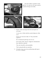
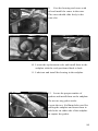
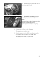
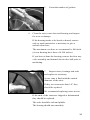
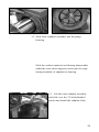
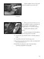
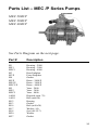
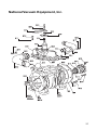
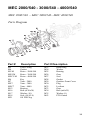
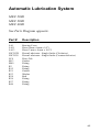
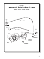
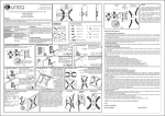
1
MEC 2000/P
MEC 3000/P
MEC 4000/P
Owner’s Record
Date of Purchase: ____________________________
Purchased from: _____________________________
Model: ______________________________________
Serial Number: _______________________________
National Vacuum Equipment, Inc.
© 1998 National Vacuum Equipment, Inc.
No part of this manual may be reproduced without the written
permission of National Vacuum Equipment, Inc.
1098
Contents
Introduction
About National Vacuum Equipment, Inc. . . . . . . . 5
Limited Warranty
Warranty . . . . . . . . . . . . . . . . . . . . . . . . . . . . . . . . 7
Warranty Procedures . . . . . . . . . . . . . . . . . . . . . . . 9
The MEC Series Pumps
Pump Specifications . . . . . . . . . . . . . . . . . . . . . . 11
Performance . . . . . . . . . . . . . . . . . . . . . . . . . . . . 12
System requirements . . . . . . . . . . . . . . . . . . . . . . 13
Operating Instructions
Installation . . . . . . . . . . . . . . . . . . . . . . . . . . . . . .
Lubrication procedure . . . . . . . . . . . . . . . . . . . . .
Automatic oil pump . . . . . . . . . . . . . . . . . . . . . . .
Adjusting the automatic oil pump . . . . . . . . . . . .
Recommended lubrication . . . . . . . . . . . . . . . . .
Normal operation for air cooled pumps: . . . . . . .
Maintenance . . . . . . . . . . . . . . . . . . . . . . . . . . . .
Determining the rotation of the pump . . . . . . . . .
15
16
16
17
18
18
19
20
Troubleshooting
Pump overheats . . . . . . . . . . . . . . . . . . . . . . . . . .
Too much oil use . . . . . . . . . . . . . . . . . . . . . . . . .
Pump doesn’t turn . . . . . . . . . . . . . . . . . . . . . . . .
No vacuum or pressure in tank . . . . . . . . . . . . . .
21
21
21
22
Pump Rebuilding
Vane replacement . . . . . . . . . . . . . . . . . . . . . . . . 23
Complete rebuild . . . . . . . . . . . . . . . . . . . . . . . . . 29
Table of Contents continues on next page.
Parts List - MEC /P Series Pumps
Parts List . . . . . . . . . . . . . . . . . . . . . . . . . . . . . . . 35
Parts Diagram . . . . . . . . . . . . . . . . . . . . . . . . . . . 36
Parts List - MEC /540 Series Pumps
Parts List and Diagram . . . . . . . . . . . . . . . . . . . . 38
Parts List - MEC Mixer Valve Manifold
Parts List and Diagram . . . . . . . . . . . . . . . . . . . . 39
Parts Details - Lubrication Systems
Automatic Lubrication System . . . . . . . . . . . . . . 40
Automatic Oil Pump . . . . . . . . . . . . . . . . . . . . . . 42
Gear-Type Lubrication System . . . . . . . . . . . . . . 44
Index
4
Introduction
General Information
NVE
About National Vacuum Equipment, Inc.
Congratulations! You now own a quality vacuum/pressure
pump exclusively distributed in North America by National
Vacuum Equipment, Inc. You have not only acquired a
superior piece of equipment from a qualified dealer, you have
hired a team of vacuum experts. We stand ready to work with
your dealer to answer your questions and provide you with the
information necessary to keep your equipment in peak
working condition.
Thank you for using National Vacuum Equipment.
OUR MISSION:
We are dedicated to the manufacture and wholesale
distribution of quality vacuum system products at a reasonable
price, on a timely basis. We are a “one-stop shop” for
manufacturers and distributors of vacuum equipment.
5
OUR HISTORY:
National Vacuum Equipment, Inc. was founded in 1980 by
Bruce Luoma. The Company started as a retailer of vacuum
pumps. Soon after it started, the Company secured the rights
to exclusive distribution of the Battioni vacuum pumps in
North America. This helped the Company to evolve into its
current status as a wholesale supplier.
To reach the goal of becoming a full service supplier of
vacuum system components, the Company began fabricating
its own line of componentry, purchased and developed its own
line of vacuum pumps, and began purchasing for resale
various valves and accessories.
Today, NVE has full service machine and fabrication shops
complete with CNC-controlled production equipment
designed for close tolerance work. The company has a highly
trained staff all of whom are dedicated to quality.
6
Be sure to line up the oil pump drive key and the oil
pump shaft prior to tightening the assembly to the
pump.
23. Connect the oil lines to the oil pump.
The pump is now ready to run.
24. Start the pump at a slow RPM and allow to run for a
few minutes until oil can be seen in the lines or
dripper.
Limited Warranty
MEC 2000/P
MEC 3000/P
MEC 4000/P
National Vacuum Equipment, Inc.
guarantees that the product it provides is free of
manufacturer’s defects, including materials and
workmanship. Properly installed and maintained
product is warranted for a period of one (1) year
subject to the following conditions:
1.
A properly completed warranty registration card must
be received by us within 30 days of sale to end user
for pump sales to be considered warrantable. All
7
pumps received for warranty consideration must
retain the original NVE serial number tag.
2.
The one (1) year period shall begin the day the
product is shipped from our warehouse, unless we are
provided with an authentic copy of the original resale
invoice, in which case the one (1) year period shall
begin at such invoice date.
3.
The covered product must be used in an application
for which it was intended. We do not recommend our
product for particular uses or applications.
4.
Vane breakage, or damage caused by vane breakage,
is not warrantable.
5.
Damage caused by improper use or lack of proper
maintenance is not warrantable.
6.
Manufacturer’s liability under this or any other
warranty, whether express or implied, is limited to
repair of or, at the manufacturers option, replacement
of parts which are shown to have been defective
when shipped.
7.
Manufacturer’s liability shall not be enforceable for
any product until National Vacuum Equipment, Inc.
has been paid in full for such product.
8.
Except to the extent expressly stated herein,
manufacturer’s liability for incidental and
consequential damage is hereby excluded to the full
extent permitted by law.
8
9.
Manufacturer’s liability as stated herein cannot be
altered except in writing signed by an officer of
National Vacuum Equipment, Inc.
10. Certain products provided by National Vacuum
Equipment, Inc. are covered by their respective
manufacturer’s warranties (e.g., engines used in the
NVE engine drive packages). These products are not
covered by the National Vacuum Equipment, Inc.
Manufacturer’s Warranty.
Should a potential warranty situation arise, the following
procedures must be followed:
•
Contact your dealer immediately upon the
occurrence of the event and within the warranty
period.
•
Customer must receive a return goods authorization
(RGA) before returning product.
•
All serial-numbered products must retain the NVE
serial number tag to be qualified for warranty.
•
Product must be returned to NVE intact for
inspection before warranty will be honored.
•
Product must be returned to NVE freight prepaid in
the most economical way.
•
Credit will be issued for material found to be
defective upon our inspection, based upon prices at
the time of purchase.
9
10
The MEC Series Pumps
Model-Specific Information
for the
MEC 2000/P
MEC 3000/P
MEC 4000/P
MEC Series Pump Specifications
Model Number
2000
RPM Range
800–1400
Max. Air Flow-CFM
90
Max. Continuous Vacuum
20
Max. Intermittent Vacuum
27
Max. Continuous Pressure
15
Max. Intermittent Pressure
30
Pump Drive Rotation
CW/CCW
Porting Size
2 inch
Manifold With Four Way Valve
Std
Oil Tank Capacity-Quarts
1
Bearings Sealed From Pump Interior
Std
Anti-Spin Check Valve
Std
Automatic Lubrication System
Opt
Net Weight
156
3000
800–1400
120
20
27
15
30
CW/CCW
2 inch
Std
1 1/4
Std
Std
Opt
183
4000
800–1400
145
20
27
15
30
CW/CCW
2 inch
Std
1 1/2
Std
Std
Opt
209
11
Performance
MEC 2000/P PERFORMANCE
PRESSURE PSI
RPM
1400
1200
1000
VACUUM – INCHES OF MERCURY
30
25
HP
12
11
9
8
6
4
3
4
4
4
4
5
5
5
6
6
CFM
67
70
73
76
80
85
90
88
87
86
84
80
77
71
64
42
HP
11
9
8
6
5
3
2
3
3
3
3
4
4
4
5
5
CFM
54
57
61
66
68
72
75
74
72
70
68
64
60
54
40
30
20
15
10
5
0
3
6
9
12
15
18
21
24
27
H.P
9
8
6
5
4
3
2
2
2
2
3
3
3
4
4
4
CFM
41
44
48
51
55
58
63
62
60
58
56
54
48
42
30
20
MEC 3000/P PERFORMANCE
PRESSURE PSI
RPM
1400
1200
1000
VACUUM – INCHES OF MERCURY
30
25
20
15
10
5
0
3
6
9
12
15
18
21
24
27
HP
20
18
15
12
10
7
6
6
6
7
7
7
8
8
8
9
CFM
97 100 103 107 111 116 120 118 116 114 112 110 105 100 90
72
HP
15
13
12
10
8
6
5
6
6
6
6
7
7
CFM
81
84
87
90
95
98 104 102 100 97
94
91
87
80
70
55
H.P
12
11
10
8
7
5
4
4
4
5
5
5
5
5
6
6
CFM
63
65
68
72
76
82
87
85
83
81
78
75
70
65
55
35
5
5
5
MEC 4000/P PERFORMANCE
PRESSURE PSI
RPM
HP
1400
1000
30
25
20
15
10
5
0
3
6
9
12
15
18
21
24
27
23
20
18
15
12
9
6
7
7
8
8
8
9
9
9
10
CFM 118 122 125 130 133 138 145 143 140 138 134 131 128 120 110 90
HP
1200
VACUUM – INCHES OF MERCURY
19
17
15
12
10
7
5
5
6
6
6
6
7
7
8
8
CFM 102 106 109 111 116 120 128 125 123 120 117 115 110 100 90 75
H.P
15
14
12
10
8
5
5
6
6
6
7
CFM
81
83
85
90
95 100 108 105 102 100 96
92
85
80
68
45
6
4
4
4
4
12
System requirements
High quality components
•
The pump body and rotor are constructed of cast iron
with free sliding vanes made of special nonmetallic,
heat resistant material.
•
Because vanes are nonmetallic, flammable fluids may
be handled without danger.
•
Vanes wear evenly because tips always remain in
contact with the wall surface.
•
For maximum life and proper performance we
recommend the use of our compatible components,
Portal F-801-2A, Moisture Trap F-901-2A, and Oil
Catch Muffler F-1002-4A.
13
14
Operating Instructions
MEC 2000/P
MEC 3000/P
MEC 4000/P
Installation
•
Check pump rotation. See Determining the Rotation
of Pump.
•
Pump should always be mounted in a level,
horizontal position on a firm, flat surface.
•
Grade 5 bolts should be used in installation. It is
important to use flat washers and lock washers.
•
We recommend the use of oil resistant hose on both
the inlet and outlet sides of the pump. If using direct
drive system, always use a flexible coupling. We
recommend the use of Woods Sure Flex Couplers.
•
If a muffler is used on discharge side of pump, inlet
and outlet of muffler must be at least equal to inside
diameter of pump outlet.
15
Lubrication procedure for all vacuum pumps on start up
(This procedure must be followed prior to the operation of a new
vacuum pump.):
•
With force feed lubrication type, install dripper on
top of pump and connect rubber lines.*
•
Remove dipstick and fill oil reservoir with
recommended turbine oil.
•
With 540 RPM pumps: fill gear housing to level of
clear plastic sight plug on the side of the housing
with SAE 90 gear oil.
•
Remove plastic cap on air inlet and pour 2 oz. turbine
oil into pump. Start pump slowly and with valve in
suction position, pour 2 oz. turbine oil into air inlet.
•
At this point oil should be visible in the dripper or oil
lines. Adjust dripper flow to 1 drop every 2 seconds.
*Dripper will be shipped loose or taped to the bottom
of the changeover valve handle.
Automatic oil pump
•
The automatic oil pumps are set at the factory
during pump testing and should require no further
adjustment during pump installation.
•
The pumps are adjusted to one drop every two
seconds per outlet. This oil rate equals 2.7 fluid oz.
per hour.
16
Adjusting the automatic oil pump
The automatic oil pump is a metered piston-type pump.
If you wish to adjust the pump, please follow these instructions:
Adjusting the oil rate
Oil flow is changed by adjusting the length of the stroke of
the piston.
1.
To adjust the oil rate, remove cap #P16. Under this
cap you will find a jam nut #P15 and adjusting screw
#P11.
2.
To adjust oil rate loosen jam nut and turn adjusting
screw clockwise to reduce oil flow or
counterclockwise to increase oil flow.
3.
When making adjustments do so one turn of the
screw at a time and test before making further
adjustments.
4.
Be careful to not turn adjusting screw too far
counterclockwise as you may disengage the gears
and strip them out.
17
Testing flow rate after adjustment
1.
Observe oil drip rate in oil view meter or oil line to
ensure adequate lubrication.
2.
Adjustments should be done gradually so as not to
starve the vacuum pump of oil.
Recommended lubrication
We recommend that turbine grade oil be used in all our pumps. Turbine oil is
more highly refined than motor oil and is much less likely to create carbon.
Turbine oil is available from your local oil distributor. Below is a list of acceptable oils.
•
Penzoil Penzabell 68 T.O.
•
Shell Turbo 68
•
Mobil D.T.E. Heavy – Medium
•
Texaco Regal R.N.O. 68
Normal operation for air cooled pumps:
1.
Check oil reservoir daily and fill as required.
2.
When pump is in operation check oiler to insure flow
of oil to pump.
3.
Do not operate pump faster than recommended RPM.
4.
To operate suction valve on top of pump, move
handle in the appropriate direction for either vacuum
or pressure; center it for neutral.
5.
We recommend checking vane wear every twelve
months. A new vane is nearly flush with the rotor.
Measure the wear and if is over 1/4" we recommend
replacing vanes. It’s good to always keep a spare set
of vanes on hand for emergencies.
18
Maintenance
•
With force feed type, the lubrication rate is
adjustable at dripper and should be checked on a
regular basis. Oil should be supplied to pump at a
rate of 1 drop every 2 seconds.
•
Average usage of oil is approximately 1 Gal. per 10
hours, depending on operation.
•
Oil should be changed every 2000 hours in gear per
housing, if equipped.
•
Front bearing should be greased approximately every
4 months. Use caution when greasing bearing not to
over grease, as this can cause damage to seals.
•
Normal vane life is approximately 2000 hours;
however, this will vary greatly with temperature,
material being pumped and proper maintenance.
•
Occasionally liquid and dirt may enter the pump
causing vanes to stick in the rotor slots along with
excessive vane and housing wear. When this occurs
you must clean the inside of the pump.
Cleaning the inside of the pump
•
Remove air inlet hose or pressure relief valve.
•
Run pump at an idle with the changeover valve in
neutral.
•
Pour 1 pint of diesel fuel into pump through the air
inlet or fitting. Allow pump to run for 30 seconds
then turn the change over valve to vacuum.
•
Repeat two steps above several times, and then pour
2 oz. of oil into the pump and reassemble.
•
Stop pump and turn slowly by hand while listening
for vanes dropping. All vanes should move freely in
the rotor slot.
19
•
It is good practice to clean your pump on a regular
basis as this will normally increase the life of your
pump greatly.
•
Vane wear should be checked every 12 months. A
new vane will be flush with the outside diameter of
the rotor.
•
When vane wear exceeds 1/4" the vanes should be
replaced. It is a good idea to have an extra set of
vanes, seals and gaskets on hand at all times.
Determining the rotation of the pump
As one faces the drive end of the pump:
•
For 1000 RPM pumps with the oiler on the right side,
the pump shaft turns clockwise.
•
For gear driven pumps (540 RPM) with the oiler on
the right side, the pump shaft turns counterclockwise.
•
If you must change the rotation of your pump contact
the factory for instructions before attempting it.
20
Troubleshooting
MEC 2000/P
MEC 3000/P
MEC 4000/P
Pump overheats
•
No oil in pump
•
Oil adjustment set too lean
•
Rpm too fast
•
Prolonged operation
Too much oil use
•
Oil adjustment set too rich
•
Oil seals defective
•
Cracked pump body
Pump doesn’t turn
•
Broken vane
•
Frozen
•
Pump endplate bolts too tight
•
Faulty PTO or drive set up
21
No vacuum or pressure in tank
•
Suction valve in neutral
•
Defective seal or vanes
•
Pump not driven fast enough
•
Check valve or suction line clogged
•
Leak in tank or fittings
22
Pump Rebuilding
MEC 2000/P
MEC 3000/P
MEC 4000/P
Please read
these instructions
completely before
attempting repair.
Vane checking
1. MEC pumps are equipped with a
vane checking port.
2. Remove the Allen head plug in an
endplate.
3.
Measure the wear.
4. If the wear is more than 1/4” the
vanes should be replaced.
Vane replacement
1.
Clean off the exterior of the pump.
2. Remove the oil supply line at the
oil pump and drain the oil tank.
23
3. Remove the 3 6x20mm screws
attaching the oil pump assembly to the
vacuum pump.
4. Remove the oil pump drive key
from the end of the rotor.
5.
Remove the six bolts that attach the endplate to the
pump.
Secure two 10x50mm bolts to screw into pull holes.
Screw the bolts into the pull holes evenly and pull off
the endplate.
If you cannot locate 10x50mm bolts, you can use the
endplate bolts and shim behind the endplate as the
endplate comes off.
24
6. Note the number of gaskets on the
endplate. You must use the same number
of gaskets during reassembly.
7.
Inspect vanes, bearings and seals and replace as
necessary.
A new vane is flush with the outside diameter of the
rotor.
If they are worn more than 1/4" they should be
replaced.
We recommend replacing vanes in sets.
If the ends of the vanes are chipped or delaminated
they should be replaced.
The seals should be soft and pliable.
The bearing should turn smoothly.
8.
Clean the rotor, rotor slots and housing and inspect
for wear or damage.
25
9. Coat the housing and vanes with
oil and install the vanes in the rotor.
The vanes should slide freely in the
vane slot.
10. Locate the replacement seals and install them in the
endplate with the seals positioned back to back.
11. Lubricate and install the bearing in the endplate.
12. Locate the proper number of
gaskets and install them on the endplate.
Do not use any gasket sealer.
Locate the two 10x50mm bolts used for
pulling the endplate and insert them in
bolt holes on either side of the endplate
to capture the gasket.
26
13. Lubricate seal sleeve and install
the endplate on the end of the rotor and
carefully drive the endplate on the rotor.
14. When the endplate is close enough
to the housing install the endplate bolts
lift the endplate-rotor assembly to allow
proper alignment of the bolts and bolt
holes and start the bolts into the housing.
Just prior to making contact with the
housing, lift the endplate -rotor
assembly again to insure proper
clearance between the rotor and the
housing.
Tighten endplate bolts to 35-40 ft lb of torque.
15. Seat the bearing with a bearing
driver or punch.
27
16. At this point you should be able to
turn the pump by hand.
17. Reinstall the oil pump drive key
and oil pump mount assembly to the
pump.
Be sure to line up the oil pump drive key
and the oil pump shaft prior to
tightening the assembly to the pump.
18. Connect the oil lines to the oil pump .
The pump is now ready to run.
19. Start the pump at a slow RPM and allow to run for a
few minutes until oil can be seen in the lines.
The pump is now ready to go to work.
28
Complete rebuild
1.
Follow steps 1-7 in the vane replacement
instructions.
2. Place a cushion under the rotor to
prevent damage when the front endplate
is unbolted.
3. Remove the six bolts attaching the
endplate to the housing.
Support the rotor shaft prior to
loosening the last bolt.
Slide the rotor out
4. Remove the front endplate, front
bearing and bearing cover from the rotor
with a puller or hydraulic press.
Put an identifying mark on the endplate
so as to not confuse it with the rear.
29
5.
6.
Count the number of gaskets.
Clean the rotor, rotor slots and housing and inspect
for wear or damage.
If the housing needs to be bored or honed, remove
only as much material as is necessary to give a
smooth clean bore.
The maximum over bore we recommend is .060 inch.
(A new housing has a bore of 6.300 inches.)
If you bore or hone the housing, remove the four way
valve assembly and internal check valve ball prior to
machining.
7. Inspect vanes, bearings and seals
and replace as necessary.
A new vane is flush with the outside
diameter of the rotor.
If they are worn more than 1/4" they
should be replaced.
We recommend replacing vanes in sets.
If the ends of the vanes are chipped or delaminated
they should be replaced.
The seals should be soft and pliable.
The bearing should turn smoothly.
30
8. Locate the replacement seals and
install them in the endplates with the
seals positioned back to back.
Replace the seal in the bearing cover
with the lip facing outward.
9. Lubricate and install the bearings
in the endplates.
10. Locate two pieces of threaded rod
3/8-18 thd. to use as guides and screw
them into the two top holes in the
housing.
Locate proper number of gaskets and
slide on the threaded rods.
Do not use any gasket sealer.
11. Lubricate the housing bore.
12. Lubricate seal sleeve and drive the
proper endplate on the input end of the
rotor.
31
13. Slide rotor-endplate assembly into the pump
housing.
Slide the cushion material used during disassembly
under the rotor on the opposite end to gain leverage
during assembly of endplate to housing.
14. Lift the rotor-endplate assembly
and slide over the 3/8 inch threaded
guides and install the endplate bolts.
32
Tighten the bolts sufficiently to
make contact between the endplate and
the housing.
15. Coat vanes with oil and install the
vanes in the rotor. The vanes should
slide freely in the vane slots.
16. Locate the proper number of
gaskets and install them on the rear
endplate.
Do not use any gasket sealer.
Locate the two 10x50mm bolts used for
pulling the endplate and insert them in
bolt holes on either side of the endplate
to capture the gaskets.
17. Lubricate seal sleeve and install the
endplate on the end of the rotor and
carefully drive the endplate on the rotor.
18. When the endplate is close enough to the housing
install the endplate bolts lift the endplate-rotor
assembly to allow proper alignment of the bolts and
bolt holes and start the bolts into the housing.
Just prior to making contact with the housing, lift the
endplate-rotor assembly allow the endplate to enter
the housing.
33
Tighten endplate bolts to the point
where the endplate just touches the
housing.
19. With a prybar and a block of wood,
lift the endplate to make certain the seal
gap is properly set and tighten the
endplate bolts to 35-40 ft lb of torque.
Tighten both endplates in this
manner.
20. Seat the bearings on both endplates
with a bearing driver or punch.
21. At this point you should be able to turn the pump by
hand.
22. Install the seal in the front bearing cover.
Lubricate the seal and seal surface on the rotor and install
the front bearing cover.
Reinstall the oil pump drive key, oil pump mount
assembly, and gaskets to the pump.
34
Parts List – MEC /P Series Pumps
MEC 2000/P
MEC 3000/P
MEC 4000/P
See Parts Diagram on the next page.
Part #
Description
M1
ME1
MEC1
M3
M3/P
M4
M5/P
ME5/P
MEC5/P
M5
ME5
MEC5
AM10
AM11
M12
M13
M16
M17
M18
M20
M27
Housing - 2000
Housing - 3000
Housing - 4000
Rear Endplate
Front Endplate
Gasket
Rotor - 2000/P
Rotor - 3000/P
Rotor - 4000/P
Vane - 2000
Vane - 3000
Vane - 4000
Dipstick (mm .79)
Bolt (m8x20)
Bearing
Gasket
Bolt (m10x30)
Washer (10)
Seal (40-52-7)
Washer
Gasket
35
Parts Diagram
MEC 2000/P
MEC 3000/P
MEC 4000/P
Parts list continued from previous page.
Part #
Description
Part #
Description
M34
M35
M36
M39
M40
M41
M45
M48
M49
M50
M51
M52
M53
Bolt (m8x25)
Washer (8)
Exhaust Pipe
Gasket
Seal (30-40-7)
Non-Return Ball
Spring
Bearing Cover Plate
Fitting
Washer
Bolt
Key
Seal (35-52-10)
M60
M62
M63
M64
M65
M66
M67
M68
M83
Handle
4-way Valve Plug
Flange
O-Ring
4-way Valve Cover
Bolt (m10x40)
4-way Valve Housing
4-way Valve Cover Gasket
2" Hose Connection
M4
M3
M49
M13
M18
M12
M48
M50
M53
M20
M34
M19
M17
M16
36
National Vacuum Equipment, Inc.
37
MEC 2000/540 - 3000/540 - 4000/540
MEC 2000/540 – MEC 3000/540– MEC 4000/540
Parts Diagram
Part #
Description
M2
M4
M5/M
ME5/M
MEC5/M
M6
M7
ME7
MEC7
M12
M16
M17
M18
M21
Gear Casing
Gasket
Rotor - 2000/540
Rotor - 3000/540
Rotor - 4000/540
Key
Vane - 2000
Vane - 3000
Vane - 4000
Bearing
Bolt (m10x30)
Washer (10)
Seal (48-62-8)
Oil FIll Plug
Part # Description
M23
M24
M25
M26
M27
M28
M29
M30
M32
M33
M34
M35
M43
Drain Plug
Washer
Bearing
Gear
Seal
Gasket
Gearbox Front Cover
Plug
Locknut
Gear
Bolt (m8x25)
Washer (8)
PTO Guard
38
MEC 2000 - 3000 - 4000
Mixer Valve Manifold
MEC 2000 – MEC 3000 – MEC 4000
Mixer Valve Manifold
Parts Diagram
Part #
Description
Part #
Description
M8
M10
M11
M16
M17
M34
M35
M39
M40
M44
M45
Fitting
Dipstick
Bolt
Bolt
Washer
Bolt
Washer
Gasket
Seal
Dripper
Spring
M46
M60
M63
M64
M66
M69
M72
M83
M84
M85
Hose
Handle
Flange
O-ring
Bolt
4-Way Valve Housing
Gasket
2” Hose Connection
Mixer Valve Cover
4-Way Valve Plug
39
Automatic Lubrication System
MEC 2000
MEC 3000
MEC 4000
See Parts Diagram opposite.
Part #
Description
LA1
LA11
LA13
LW32CD
LW32CS
LF8
M13
M49
R3
R15
R31
R33
R34
R36
R37
R46
Bearing Cover
Hose (4mm x 6mm x 9.5")
Hose (2 mm x 4 mm x 18.5")
Piston Lubricator - Single Outlet (Clockwise)
Piston Lubricator - Single Outlet (Counterclockwise)
Drive Tab
Gasket
Fitting
Fitting
Fitting
Gasket
Washer
Bolt
Fitting
Fitting
Fitting
40
Detail
Automatic Lubrication System
MEC 2000 - 3000 - 4000
R15
LA13
R46
R37
LA11
R37
R33
LA1
R31
R34
R3
LF8
R36
LW32CD
LW32CS
M13
M49
41
Automatic Oil Pump
See Parts Diagram opposite.
Part #
Description
P 1CW
P 1CCW
P5
PA 5
P6
P 7CW
P 7CCW
P8
P9
P 10
P 11
P 12
P 13
P 14
P 15
P 16
Pump Body – 1 outlet (Clockwise)
Pump Body – 1 outlet (Counterclockwise)
Driven Gear (Clockwise)
Driven Gear (Counterclockwise)
Spring
Driving Gear (Clockwise)
Driving Gear (Counterclockwise)
Seal
Plug
Retainer
Adjusting Screw
Gasket
Lid
Screw
Jam Nut
Cap
42
Detail
Automatic Oil Pump
Two
One Outlet Type
Part # LW32CD
Clockwise
– One Outlet
Part # LW32D
Clockwise
Part # LW32CS
Counterclockwise
– One Outlet
Part # LW32S Counterclockwise
43
Gear-Type Lubrication System
MEC 2000/P
MEC 3000/P
MEC 4000/P
See Parts Diagram opposite.
Part #
Description
LF1
LF2
LF3
LF4
LF6
LF7
LF8
LF12
LF12CCW
LF12G
LF12GL
LF13
LF15
LF17
LF19
LF20
LF21
LF22
M13
Cover Plate
Cover Plate Gasket
Drive Gear
Driven Gear
Bolt
Oil Pump Housing
Drive Tab
Dripper – T-Type (Clockwise)
Dripper – V-Type (Counterclockwise)
Dripper Gasket
Dripper Glass
Fitting (Housing Oil Reservoir - M10 x 1)
Hose (5mm x 10.5 mm x 6.75")
Fitting (Gear Type Oil Pump - M6 x 1)
Hose (5mm x 10.5 mm x 8.5")
Hose (5mm x 10.5 mm x 18.5")
Oil Line Per Foot
Oil Pump – Complete
Gasket
Detail
Gear-Type Lubrication System
MEC 2000/P • MEC 3000/P • MEC 4000/P
LF12
LF20
LF19
LF15
LF13
LF17
LF17
LF17
LF1
LF3
LF7
LF8
LF6
LF2
M13
LF4
45
Index
A
H
P
Air Flow 11
Automatic Lubrication 40
Automatic Lubrication
System 40
Automatic Oil Pump 42
Hose 15
Housing 25, 29, 35
Housing bore 31
Housing, boring or honing 30
Hydraulic press 29
B
I
Bearing
11, 19, 25, 29, 30, 34
Bearing cover 29, 31
Bearing driver 34
Bore 30
Identifying mark 29
Installation 15
Instructions, rebuilding 23
Parts Diagram 36
Parts Diagram Foldout
35, 40, 42, 44
Parts List 35, 40, 44
Performance 12
Piston 17
Portal F-801 13
Porting size 11
Pressure, continuous 11
Pressure, intermittent 11
Pressure relief valve 19
Prybar 33
PTO 21
Pull holes 24
Puller 29
Pump body 13
Pump doesn’t turn 21
Pump, piston-type 17
Punch 34
C
Check Valve, Anti-Spin 11
Check valve ball 30
Cleaning 19
Clockwise 20
Components 13
Counterclockwise 20
Coupling 15
Cushion 29
Cushion material 32
D
Diesel fuel 19
Dripper 16, 19
Drive key 24, 28
E
Endplate 21, 24, 29, 32, 33
F
Factory Settings 17
Four way valve 30
G
Gasket sealer 26, 31, 33
Gaskets 20, 25, 30, 31, 33
Gear-Type Lubrication
System 44
Greasing 19
Guides 31
J
Jam nut 17
L
Lubricate 26, 31
Lubrication 11, 16
Lubrication rate 19
M
Maintenance 8
Manifold 11
Manufacturer’s warranties 8
MEC 2000/540 - 3000/540 4000/540 38
Mixer Valve Manifold 39
Muffler 15
O
Oil 19
Oil adjustment 21
Oil lines 28, 34
Oil pump 16, 34
Oil pump shaft 28
Oil rate 16
Oil reservoir 18
Oil tank capacity 11
Oil, turbine grade 18
Oil, using too much 21
Oiler 18, 20
Operation, normal 18
Overheating 21
Owner’s Record 1
R
Rebuild, complete 29
Rebuilding 23
Recommended Lubrication
18
Registration card 7
Repair 23
Return goods authorization 9
Rotation 11, 15
Rotation, changing 20
Rotor 13, 25, 29, 30, 32
Rotor shaft 29
Rotor slots 25
Rotor-endplate assembly 32
RPM 18, 21
RPM Range 11
S
Seal sleeve 27, 31
Seals 20, 21, 25, 26, 30
Serial number 7
Serial number tag 9
Specifications 11
System requirements 13
T
Tank 22
Threaded rod 31
Torque 27, 33
Troubleshooting 21
Turbine oil 18
V
Vacuum, continuous 11
Vacuum, intermittent 11
Vacuum, none in tank 22
Valve, changeover 19
Valve, check 22
Valve, four way 11
Valve, pressure relief 19
Valve, suction 18
Vane 13, 19, 21
Vane breakage 8
Vane life 19
Vane replacement 23, 29
Vane wear 18
Vanes 25, 30, 32
Vanes, chipped or delaminated
25, 30
W
Warranty 7
Warranty procedure 9
Washers 15
Weight 11
Woods Sure Flex Couplers 15