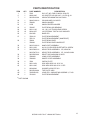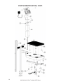
1
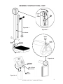
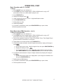
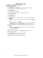
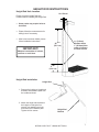
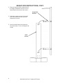
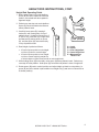
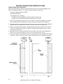
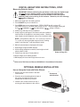
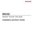
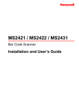
DIGITAL PHYSICIAN
Eye-Level Scale
Model 6437 Series
Operating Instructions
0033-M114-O1 Rev F
10/12
CARDINAL SCALE MFG. CO.
PO BOX 151 x WEBB CITY, MO 64870
PH (417) 673-4631 x FAX (417) 673-5001
www.detectoscale.com
Technical Support: Ph: 866-254-8261 x [email protected]
Printed in USA
DIGITAL PHYSICIAN EYE-LEVEL SCALE
Thank you for purchasing our Detecto Digital Physician Eye-Level Model 6437 Series Scale. It
has been manufactured with quality and reliability at our factory in Webb City, MO USA. Your
scale has been tested before leaving our factory to insure accuracy and dependability for years
to come.
This manual is provided to guide you through the operation of your scale. Please read it
thoroughly before attempting to operate your scale and keep it handy for future reference.
SPECIFICATIONS
Capacity ……..……..….… 6437, 6437DHR, 6439, 6449: 550 lb x .2 lb (250 kg x .1 kg)
6439M, 6449M: 550 lb x .2 lb (250 kg x .1 kg)
6437KG, 6437KGDHR, 6439KG: 250 kg x .1 kg
6438, 6447: 550 lb x .2 lb
Platform Size ………..…... 10.5” x 14.5” (27 cm x 37.5 cm)
Shipping Weight ……....… 6437, 6437DHR: 35 lb (15.4 kg)
6439, 6439M: 38 lb (17.2 kg)
6449, 6449M: 46 lb (20.8 kg)
Scale Height …………….. 59” (150 cm)
Height Rod Measures ….. 6437DHR: 43” to 78” (110 cm to 200 cm) x inch/cm
6439, 6449: 30” to 78” (76 cm to 200 cm) x inch/cm
6439M, 6449M: 30” to 78” (76 cm to 200 cm) x 1/4 inch/1mm
Display ………………..….. Weight: Five digit, seven segment, 1/2” (13 mm) high LCD
Height: Four digit, seven segment, 3/8" (10 mm) high LCD
Power ………………......... 6 “C” cell Alkaline, Ni-Cad or NiMH batteries (not included) OR an
optional 100 to 240 VAC 50/60Hz 12 VDC 1A wall plug-in UL/CSA
listed AC power adapter (Cardinal part number 6800-1045).
Keyboard .......................... Membrane type with 19 keys, On/Off, Lock/Release, Units, Zero,
Net/Gross, Tare ID/Height, Print/Enter and 0-9 Numeric Keys
All rights reserved. Reproduction or use, without expressed written permission, of editorial or
pictorial content, in any manner, is prohibited. No patent liability is assumed with respect to
the use of the information contained herein. While every precaution has been taken in the
preparation of this manual, the Seller assumes no responsibility for errors or omissions.
Neither is any liability assumed for damages resulting from use of the information contained
herein. All instructions and diagrams have been checked for accuracy and ease of application;
however, success and safety in working with tools depend to a great extent upon the individual
accuracy, skill and caution. For this reason the Seller is not able to guarantee the result of any
procedure contained herein. Nor can they assume responsibility for any damage to property or
injury to persons occasioned from the procedures. Persons engaging the procedures do so
entirely at their own risk.
Serial Number_______________________
Date of Purchase ____________________
Purchased Form_____________________
PRECAUTIONS
Before using this instrument, read this
manual and pay special attention to all
"WARNING" symbols:
___________________________________
___________________________________
IMPORTANT
RETAIN THIS INFORMATION FOR FUTURE USE
0033-M114-O1 Rev F x Model 6437 Series
ELECTRICAL
WARNING
1
UNPACKING INSTRUCTIONS
x
Remove scale from carton by lifting up with equal force from column and platform base.
x
Check for any damage incurred in shipping. If scale has been damaged, place a claim with
the carrier. Use the original carton and shipping material to return the scale.
x
Remove all plastic wrapping, foam fillers and cardboard material from the scale.
x
Carton contents:
1)
2)
3)
4)
5)
6)
7)
Column
Indicator
Platform base
Screws and lock washers
Hand post - optional
Height measuring rod - optional
Wheels - optional
NOTE! If column bracket is bent,
straighten before assembling.
ASSEMBLY INSTRUCTIONS
Refer to Figures No. 1, 2, 3, and 4, then follow the instructions for scale assembly.
1. Carefully remove load cell and draft rod assembly from column.
IMPORTANT! Handle load cell assembly with care! Do not drop, bend or twist.
2. Slip column over column bracket on platform base. Screw column to column brackets
(two 1/4 truss head screws in front of column and four in the back). See Figure No. 1.
3. Referring to Figure No. 2, remove both #10-32 Truss Head Screws and lock washers
securing the indicator bracket to the column.
4. Lower load cell and draft rod assembly into column. Draft Rod must pass through
opening in column bracket. Referring to Figure No 1, make sure open end of lower draft
rod hook is facing forward toward platform.
5. Next, referring to Figure No. 3, fasten top hook bolt of load cell assembly (C) to column.
Make sure the load cell assembly does not touch the sides of column.
6. Slide grommet away from load cell assembly and slide into slot on column. NOTE! The
slot should be on back (wide side) of column.
7. Pull excess load cell cable in column leaving enough slack in cable so as not to have
any side pull on load cell.
8. Place digital indicator bracket on column and attach with 2 (#10-32) truss head screws
and lock washers removed in step 3. See Figure No. 2.
9. Using a desk or table, lay down scale with column horizontal to floor. Raise draft rod
keeping out of lever's way. Push lever. When lever is in position, hook draft rod around
pivot. See Figure No. 4.
10. Attach indicator to indicator bracket on column, then connect load cell cable to back of
indicator. Refer to the 758C Owner’s Manual, 8555-M210-O1 for additional information.
11. Scale is now ready for operation.
2
0033-M114-O1 Rev F x Model 6437 Series
ASSEMBLY INSTRUCTIONS, CONT.
Grommet
Load
Cell
Cable
C
Figure No. 1
Figure No. 3
Column
Raise
Draft
Rod
Draft
Rod
Push
Lever
Column
Bracket
Opening
Figure No. 4
Indicator
Bracket
#10-32 Truss
Head Screw
Lock
Washer
Figure No. 2
0033-M114-O1 Rev F x Model 6437 Series
3
OPERATION
758C Keypad
Basic Operation
To Weigh
1. Press ON/OFF key to turn indicator on.
2. Press ZERO key to zero weight display. ZERO, GROSS and lb, oz, kg or ST
annunciator will turn on to show that the scale is ready for use.
3. Place patient on scale and read weight display.
4. If a printer is connected to scale, press PRINT/ENTER key to print a ticket.
5. Remove patient from scale.
Zero Weight Display
1. In Gross Weight mode (GROSS annunciator on), press ZERO key.
2. Weight display will return to zero. ZERO and STABLE [\ annunciators will turn on to
show a stable, center-of-zero gross weight condition.
Metric Conversion
Press UNITS key to toggle between pounds and kilograms. Note that the lb or kg
annunciator will turn on to show the weighing unit selected.
4
0033-M114-O1 Rev F x Model 6437 Series
OPERATION, CONT.
Basic Operation with ID – (No BMI)
To Weigh
1. Press ON/OFF key to turn indicator on.
2. Press ZERO key to zero weight display. ZERO, GROSS and lb, oz, kg or ST
annunciator will turn on to show scale is ready for use.
3. Press ID/HEIGHT key.
4. Display will change to show id=.
5. Using numeric keys, key-in up to an 11 digit identification number.
6. Press PRINT/ENTER key.
7. Place patient on scale
8. Read weight display.
9. If a printer is connected to scale, press PRINT/ENTER key to print a ticket.
10. Remove patient from scale.
Body Mass Index (BMI) Operation – (No ID)
To Weigh and Calculate BMI
1. Press ON/OFF key to turn indicator on.
2. Press ZERO key to zero weight display. ZERO, GROSS and lb, oz, kg or ST
annunciator will turn on to show scale is ready for use.
3. Perform tare operation if required. Refer to Push Button Tare or Tare Weight Entry in
previous section for instructions on using tare.
4. Place patient on the scale and then press ID/HEIGHT key.
5. If Feet-Inches were selected in setup for height measurement, display will change to
show FEEt=.
a. Use numeric keys to enter 1 digit for height in feet, then press PRINT/ENTER key.
b. Display will change to show inCH=.
c. Use numeric keys to enter up to 3 digits (# # . #) for height in inches and then
press PRINT/ENTER key or press PRINT/ENTER key if no inches are required.
6. If Centimeters was selected in setup for height measurement, display will change to
show Cn=_.
a. Use numeric keys to enter up to 4 digits (# # # . #) for height in centimeters and
then press PRINT/ENTER key.
7. Read weight and BMI displays.
8. If a printer is connected to scale, press PRINT/ENTER key to print a ticket.
9. Remove patient from scale.
0033-M114-O1 Rev F x Model 6437 Series
5
OPERATION, CONT.
Body Mass Index (BMI) Operation with ID
To Weigh and Calculate BMI
1. Press ON/OFF key to turn indicator on.
2. Press ZERO key to zero weight display. ZERO, GROSS and lb, oz, kg or ST
annunciator will turn on to show scale is ready for use.
3. Press ID/HEIGHT key.
4. Display will change to show id=.
5. Using numeric keys, key-in up to an 11 digit identification number.
6. Press PRINT/ENTER key.
7. Place patient on scale.
8. Press ID/HEIGHT key.
9. If Feet-Inches were selected in setup for height measurement, display will change to
show FEEt=.
a. Using numeric keys, enter 1 digit for height in feet and then press PRINT/ENTER
key.
b. Display will change to show inCH=.
c. Using numeric keys enter up to 3 digits (# # . #) for height in inches and then press
PRINT/ENTER key or press PRINT/ENTER key if no inches are required.
10. If Centimeters was selected in setup for height measurement, display will change to
show Cn=_.
a. Using numeric keys enter up to 4 digits (# # # . #) for height in centimeters and
then press PRINT/ENTER key.
11. Read weight and BMI displays.
12. If a printer is connected to scale, press PRINT/ENTER key to print a ticket.
13. Remove patient from scale.
14. Press NET/GROSS key to return to Gross weight mode.
15. Press ZERO key. This will reset tare weight to zero.
16. BMI display and ID will clear when weight returns to zero.
6
0033-M114-O1 Rev F x Model 6437 Series
HEIGHT ROD INSTRUCTIONS
Height Rod Hole Location
2in (51mm)
Please check the Height Rod hole
locations before installing the Height Rod.
x
Some scales may require holes to
be drilled.
x
Please follow the measurements for
drilling holes if necessary.
x
After holes have been drilled, please
follow installation instructions.
9/64”
47/64”
29
(75.5 cm)
IMPORTANT!
(3.5mm)
diameter holes,
1” (25.4mm) from
center of column
to center of hole
Measure from bottom of column,
not floor or scale base.
5 15/64”
(13.3 cm)
Height Rod Installation
Height Rod
1. Remove the height rod, height rod
brackets and hardware pack from
the cardboard insert.
2. Attach the height rod brackets to
the height rod using the four
screws, lock washers and nuts
enclosed in the hardware pack.
Tighten all four screws.
Height Rod
Bracket
0033-M114-O1 Rev F x Model 6437 Series
7
HEIGHT ROD INSTRUCTIONS, CONT.
3. Place the large end of the slotted holes in
the height rod brackets over the four hex
head screws on the back of the column.
Height Rod
Bracket
4. Pull down to set the screws in the small
end of the slotted hole and secure the
bracket to the column.
5. Use the included wrench to tighten the
hex head screws. Do not over-tighten the
screws.
Scale
Column
8
0033-M114-O1 Rev F x Model 6437 Series
HEIGHT ROD INSTRUCTIONS, CONT.
Height Rod Operating Guide
1. Before patient steps onto scale platform,
spoon (B) should be rotated to horizontal
position, and raised well above patient's
apparent height.
2. Patient may now step onto scale platform.
Spoon (B) should be held horizontal and
above patient's head.
A
B
C
E
3. Carefully lower spoon (B), keeping it
horizontal, until it rests gently on top of
patient's head. If patient is shorter than 3'
4" (101.5 cm), push latch (A) to right while
simultaneously pushing down on spoon
(B), until the spoon (B) rests horizontally
on top of patient's head.
4. Read height of patient as follows:
x
If back of spoon points to outer height
rod, then it points to correct height.
x
If back of spoon points to inner height
rod, then correct height is read at top
of outer height rod (see "Read" arrow on outer height rod)..
D
Height Rod in
“rest” position
A = Latch
B = Spoon
C = Inner Height Rod
D = Outer Height Rod
E = Measurement
“Read” Line
5. While holding spoon (B) horizontally, raise spoon (B) above patient's head. Patient may
now step off scale platform. Hold spoon (B) horizontal until patient is clear of height rod.
6. Rotate spoon (B) back to vertical position and adjust height rod back to rest position (i.e.
spoon (B) should be locked in place within inner height rod (C) and inner rod should be at
its lowest position).
0033-M114-O1 Rev F x Model 6437 Series
9
DIGITAL HEIGHT ROD INSTRUCTIONS
Digital Height Rod Installation
Before starting installation, please unpack carefully and remove all plastic wrappings, foam
fillers and cardboard material. You should have the following components:
(1) Detecto Digital Height Rod (DHR)
(2) Mounting Brackets
(1) Hardware Pack, containing:
(8) M4x0.7x4 Pan Head Machine Screws (bracket to height rod)
(4) #10x1/2” Hex Head Sheet Metal Screws (bracket to column)
1. Align a mounting bracket with the holes in the height rod (near the headpiece) and install
four (4) M4x0.7x4 Pan Head Machine screws to secure the bracket to the height rod.
2. Next, align the other mounting bracket with the lower holes in the height rod and install four
(4) M4x0.7x4 Pan Head Machine screws to secure the bracket to the height rod.
3. Align the mounting bracket (near the headpiece) with the holes in the back of the column
close to the display and install two (2) #10x1/2” Hex Head Sheet Metal screws to secure
the bracket to the column.
4. Align the holes in the other bracket with the lower holes in the column and install two (2)
#10x1/2” Hex Head Sheet Metal screws to secure the bracket to the column.
5. Connect the cable from the DHR to the port on the rear of the 758C indicator that is labeled
height rod. Refer to the 758C Owner’s Manual, 8555-M210-O1 for additional information.
10
0033-M114-O1 Rev F x Model 6437 Series
DIGITAL HEIGHT ROD INSTRUCTIONS, CONT.
Measuring Patient’s Height
IMPORTANT! Before performing the operations on this page, the digital height
rod must be in its “starting position” (inner sliding tube must be down
completely inside outer stationary tube and headpiece folded flat against
stationary tube) prior to turning on the indicator. Otherwise, the error message
999.9 will be displayed.
1. Make sure height rod is in starting position.
2. Press ON/OFF key to turn indicator on.
3. Press ZERO key to zero weight display. ZERO, GROSS and lb, oz, kg or ST
annunciator will turn on to show scale is ready for use. Note that height reading will
show 3-&3 FT-INCHES or 110.0 cm (depending on Unit= setting in Setup¾).
4. Patient may now step onto scale platform.
5. Grasp height rod at hinge pin and raise it well above patient’s
head and then lift headpiece to horizontal position. Carefully
lower height rod until headpiece rests on top of patient’s head.
NOTE: If the patient is under 3 ft, 7.3 in (110 cm) or over 6 ft,
7.1 in (201 cm) return the digital height rod to the “starting
position” and manually¾ enter the patient’s height.
6. BMI will automatically be displayed with height.
7. Read weight, height and BMI displays.
8. While holding headpiece horizontal, raise height rod well
above patient’s head.
Grasp at Hinge Pin
9. Patient may now step off scale platform.
10. Return height rod to starting position.
11. BMI display will clear when weight returns to zero.
¾
Refer to the 758C Owner’s Manual, 8555-M210-O1 for additional information.
OPTIONAL WHEELS INSTALLATION
How to Setup the Scale with Roller Wheels.
1. Remove the two lower screws in the back
of the column.
2. Place the wheel bracket against the back of
the column and align the holes in the
bracket with the holes in the column.
Screws and
wheel bracket
3. Install the two screws removed in step 1,
securing the wheel bracket to the column.
0033-M114-O1 Rev F x Model 6437 Series
11
ERROR AND STATUS DISPLAYS
Display
-Err-OF-trL-UnSCALib
AdErr
ErrA
ErrAL
ErrAH
EE Err
OCAP
OFF
Meaning
General error, invalid keypad entry was attempted.
Attempting to display a negative number greater than –9,999 or a
positive number greater than 99,999
Indicates an attempt to zero a weight outside scale zero range. Refer to
the Setup and Calibration trL= (Four Percent Zero Tracking Range
Limit) parameter.
Motion is present when indicator is attempting to perform one of the
following operations: Power Up, Zero, or Zero Weight Display
Indicates calibration is necessary.
Consult your scale service representative.
Scale weight exceeds scale capacity
Displayed to indicate the indicator is turning off.
CARE AND CLEANING OF SCALE
x
x
x
x
x
x
12
DO NOT subject the platform to sudden shocks.
DO NOT submerge indicator in water, pour or spray water directly on indicator.
DO NOT use abrasive cleaners on this scale.
DO NOT use acetone or other volatile solvents for cleaning.
DO clean the scale and indicator using a damp soft cloth and mild detergent.
DO avoid areas where the scale might be exposed to moisture.
0033-M114-O1 Rev F x Model 6437 Series
PARTS IDENTIFICATION
ITEM
1
6
7
20
21
22
23
24
25
26
27
29
30
33
35
36
37
38
39
42
43
45
46*
48
QTY
1
1
1
1
4
1
4
10
10
4
1
1
1
1
1
2
1
1
1
1
1
2
1
2
2
1
1
1
PART NUMBER
758C
6800-1045
0033-B163-0A
0044-C180-1A
3P8059
2U58
3P2087
6021-1102
6024-1027
63K1038
3P2011X
3P511X
3P868
3P9068
0033-C106-1A
6021-1629
0033-D063-1A
0033-D475-1A
0033-B256-08
3P8002X
3P8003X
3P60
6021-1454
6021-1045
6024-0049
0033-B104-0A
709G2R1206
3P1001X
DESCRIPTION
DIG. WT. IND. FOR CLINICAL SCALES
AC ADAPTER 100-240 VAC / 12 VDC @ 1A
INDICATOR MOUNTING 6437/6439
COLUMN ASSY W/ HOLES
UNION HANGER
UNION CENTER HANGER
PLATFORM LOAD BEARING
1/4 - 20 X 1/2 TRUSS HEAD SCREW
1/4 EXTERNAL TOOTH LOCK WASHER
BASE LEG
PLATFORM WELDMENT
PLATFORM WELDMENT (HANDPOST)
PLATFORM COVER
PLATFORM COVER HANDPOST
HAND POST ASSEMBLY
#10 X 1/2 HEX HEAD SHEET METAL SCREW
HEIGHT ROD ASSEMBLY: 3P, INCH/CM
HEIGHT ROD ASSEMBLY: 3P, 1/4 INCH/1MM
DRAFT ROD 6439/6800 SCALES
LONG LEVER ASSEMBLY
SHORT LEVER ASSEMBLY
CHECK PLATE
SCW HEX HEAD 1/4 -20 X 3/4
SCW HEX HEAD #10-32 X 1/2 Z/P
WASHER LOCK EXT #10
TOP PLATE ASSY.
LOAD CELL & MOUNTING ASSEMBLY, Z-100
PLATFORM WELDMENT
* NOT SHOWN
0033-M114-O1 Rev F x Model 6437 Series
13
PARTS IDENTIFICATION, CONT.
14
0033-M114-O1 Rev F x Model 6437 Series
FCC COMPLIANCE STATEMENT
WARNING! This equipment generates uses and can radiate radio frequency and if not
installed and used in accordance with the instruction manual, may cause interference to radio
communications. It has been tested and found to comply with the limits for a Class A
computing device pursuant to Subpart J of Part 15 of FCC rules, which are designed to provide
reasonable protection against such interference when operated in a commercial environment.
Operation of this equipment in a residential area may cause interference in which case the
user will be responsible to take whatever measures necessary to correct the interference.
You may find the booklet "How to Identify and Resolve Radio TV Interference Problems"
prepared by the Federal Communications Commission helpful. It is available from the U.S.
Government Printing Office, Washington, D.C. 20402. Stock No. 001-000-00315-4.
PROPER DISPOSAL
When this device reaches the end of its useful life, it must be properly disposed of. It must not
be disposed of as unsorted municipal waste. Within the European Union, this device should
be returned to the distributor from where it was purchased for proper disposal. This is in
accordance with EU Directive 2002/96/EC. Within North America, the device should be
disposed of in accordance with the local laws regarding the disposal of waste electrical and
electronic equipment.
It is everyone’s responsibility to help maintain the environment and to
reduce the effects of hazardous substances contained in electrical and
electronic equipment on human health. Please do your part by making
certain that this device is properly disposed of. The symbol shown to the
right indicates that this device must not be disposed of in unsorted
municipal waste programs.
0033-M114-O1 Rev F x Model 6437 Series
15
STATEMENT OF LIMITED WARRANTY
Detecto Scale warrants its equipment to be free from defects in
material and workmanship as follows: Detecto warrants to the
original purchaser only that it will repair or replace any part of
equipment which is defective in material or workmanship for a
period of one (1) year from date of shipment. Detecto shall be the
sole judge of what constitutes a defect.
During the first ninety (90) days Detecto may choose to supply all
necessary replacement parts and service during normal weekday
working hours at no charge to the buyer.
After the first ninety (90) days Detecto will supply parts and
service at the job site provided the owner agrees to pay the Dealer
for all travel time, including mileage and test equipment, as well as
any expenses incurred over the direct labor of the technician at the
job site. This limited warranty honors only labor performed by
Detecto authorized dealers.
This warranty does not apply to peripheral equipment not
manufactured by Detecto; this equipment will be covered by certain
manufacturer’s warranty only.
This warranty does not include replacement of expendable or
consumable parts. This does not apply to any item which has
deteriorated or damaged due to wear, accident, misuse, abuse,
improper line voltage, overloading, theft, lightning, fire, water or acts
of God, or due to extended storage or exposure while in purchaser’s
possession. This warranty does not apply to maintenance service.
Purchased parts will have a ninety (90) day repair or replacement
warranty only.
Detecto may require components be returned to the factory; they
must be properly packed and shipping charges prepaid. A return
authorization number must be obtained for all returns and marked
on the outside of all returned packages. Detecto accepts no
responsibility for loss or damage in transit.
16
0033-M114-O1 Rev F x Model 6437 Series
STATEMENT OF LIMITED WARRANTY
Conditions Which Void Limited Warranty
This warranty shall not apply to equipment which:
A.) Has been tampered with, defaced, mishandled or have had
repairs and modifications not authorized by Detecto.
B.) Has had serial number altered, defaced, or removed.
C.) Has not been grounded according to Detecto’s recommended
procedure.
Freight Carrier Damage
Claims for equipment damaged in transit must be referred to the
freight carrier in accordance with freight carrier regulations.
This warranty sets forth the extent of our liability for breach of any
warranty or deficiency in connection with the sale or use of the
product. Detecto will not be liable for consequential damages of any
nature, including but not limited to, loss of profit, delays or expenses,
whether based on tort or contract. Detecto reserves the right to
incorporate improvements in material and design without notice and
is not obligated to incorporate improvements in equipment
previously manufactured.
The foregoing is in lieu of all other warranties, express or implied
including any warranty that extends beyond the description of the
product including any warranty of merchantability or fitness for a
particular purpose. This warranty covers only those Detecto
products installed in the forty-eight (48) contiguous continental
United States.
Ph. (800) 641-2008
E-mail: [email protected]
203 E. Daugherty
Webb City, MO 64870
0033-M114-O1 Rev F x Model 6437 Series
02/06
Printed in USA
D268-WARRANTY-DET
17
18
0033-M114-O1 Rev F x Model 6437 Series