1
About This Guide
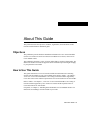
This preface discusses the objectives, audience, organization, and conventions of this
network module hardware installation guide.
Objectives
This publication provides hardware installation information for Cisco network modules
used in Cisco 3600 series and Cisco 2600 series modular access routers, referred to as
Cisco modular routers.
This publication describes a variety of router models that are similar in functionality, but
differ in the number of interfaces supported. Some information provided might not apply
to your particular router model.
How to Use This Guide
This guide contains an overview of network modules and information on connecting
specific network modules to your Cisco modular router. Refer to Table 1-1 in Chapter 1,
“Overview of Cisco Network Modules” for a listing of network modules supported by
Cisco 3600 series routers and the required release of Cisco IOS software for each module.
Refer to Table 1-2 in Chapter 1, “Overview of Cisco Network Modules” for a listing of
network modules supported by Cisco 2600 series routers and the required release of
Cisco IOS software for each module.
If required, see Chapter 3, “Installing Network Modules in Cisco Modular Routers” for
instructions on installing a network module in your router.
About This Guide ix
Audience
Refer to the Software Configuration Guide (for Cisco 3600 series and Cisco 2600 series
routers) for an overview of network module configuration procedures and information on
configuring specific network modules.
Audience
This guide is designed for the person installing the modular router, who should be familiar
with electronic circuitry and wiring practices and have experience as an electronic or
electromechanical technician.
Organization
The major sections of this guide include:
Chapter
Title
Description
Chapter 1
Overview of Cisco Network
Modules
Lists the network module options for Cisco 3600 series and
Cisco 2600 series modular routers.
Chapter 2
Preparing to Install Network
Modules
Discusses safety information, and describes the various tools and
equipment required to install a network module.
Chapter 3
Installing Network Modules in
Cisco Modular Routers
Includes basic installation information for installing network
modules in Cisco 3600 series and Cisco 2600 series modular
routers.
Chapter 4
Connecting Ethernet Network
Modules to a Network
Discusses basic hardware installation information for connecting
the various Ethernet network modules to a network, and
describes the network module LEDs.
Chapter 5
Connecting Fast Ethernet PRI
Network Modules to a Network
Discusses basic hardware installation information for connecting
the Fast Ethernet Primary Rate Interface (PRI) network modules
to a network, and describes the network module LEDs.
Chapter 6
Connecting Serial Network
Modules to a Network
Discusses basic hardware installation information for connecting
the various serial network modules to a network, and describes
the network module LEDs.
x
Cisco Network Modules Hardware Installation Guide
Organization
Chapter
Title
Description
Chapter 7
Connecting ISDN BRI Network
Modules to a Network
Discusses basic hardware installation information for connecting
the various Integrated Services Digital Network (ISDN) Basic
Rate Interface (BRI) network modules to a network, and
describes the network module LEDs.
Chapter 8
Connecting ISDN PRI Network
Modules to a Network
Discusses basic hardware installation information for connecting
the various ISDN PRI network modules to a network, and
describes the network module LEDs.
Chapter 9
Connecting Voice Network
Modules to a Network
Discusses basic hardware installation information for connecting
the various voice network modules to a network, and describes
the network module LEDs.
Chapter 10
Connecting Digital
Modem Network Modules to a
Network
Discusses basic hardware installation information for connecting
the various digital modem network modules to a network, and
describes the network module LEDs.
Chapter 11
Connecting Analog Modem
Network Modules to a Network
Discusses basic hardware installation information for connecting
analog modem network modules to a network, and describes the
network module LEDs.
Chapter 12
Connecting ATM Network
Modules to a Network
Discusses basic hardware installation information for connecting
Asynchronous Transfer Mode (ATM) network modules to a
network, and describes the network module LEDs.
Chapter 13
Connecting HSSI Network
Modules to a Network
Discusses basic hardware installation information for connecting
High-Speed Serial Interface (HSSI) network modules to a
network, and describes the network module LEDs.
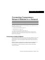
Chapter 14
Connecting Compression Network
Modules to a Network
Discusses basic hardware installation information for connecting
compression network modules to a network, and describes the
network module LEDs.
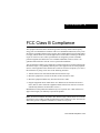
Appendix A
FCC Class B Compliance
Contains the compliance statement for a Class B digital
device that satisfies the specifications in part 15 of the FCC rules.
About This Guide xi
Conventions
Conventions
This publication uses the following conventions to convey instructions and information:
Convention
Description
boldface font
Commands and keywords.
italic font
Variables for which you supply values.
[
Keywords or arguments that appear within square brackets are optional.
]
{x | y | z}
A choice of required keywords appears in braces separated by vertical bars. You must
select one.
screen font
Examples of information displayed on the screen.
boldface screen font
Examples of information you must enter.
<
>
Nonprinting characters, for example passwords, appear in angle brackets.
[
]
Default responses to system prompts appear in square brackets.
Note
Means reader take note. Notes contain helpful suggestions or references to additional
information and material.
12
9
3
Timesaver This symbol means the described action saves time. You can save time
by performing the action described in the paragraph.
6
Caution This symbol means reader be careful. In this situation, you might do
something that could result in equipment damage or loss of data.
Warning This warning symbol means danger. You are in a situation that could cause
bodily injury. Before you work on any equipment, be aware of the hazards involved
with electrical circuitry and be familiar with standard practices for preventing accidents.
To see translations of the warnings that appear in this publication, refer to the
Regulatory Compliance and Safety Information document that accompanied this device.
Waarschuwing Dit waarschuwingssymbool betekent gevaar. U verkeert in een
situatie die lichamelijk letsel kan veroorzaken. Voordat u aan enige apparatuur gaat
werken, dient u zich bewust te zijn van de bij elektrische schakelingen betrokken
risico's en dient u op de hoogte te zijn van standaard maatregelen om ongelukken te
voorkomen. Voor vertalingen van de waarschuwingen die in deze publicatie
verschijnen, kunt u het document Regulatory Compliance and Safety Information
(Informatie over naleving van veiligheids- en andere voorschriften) raadplegen dat bij
dit toestel is ingesloten.
xii
Cisco Network Modules Hardware Installation Guide
Conventions
Convention
Description
Varoitus Tämä varoitusmerkki merkitsee vaaraa. Olet tilanteessa, joka voi johtaa
ruumiinvammaan. Ennen kuin työskentelet minkään laitteiston parissa, ota selvää
sähkökytkentöihin liittyvistä vaaroista ja tavanomaisista onnettomuuksien
ehkäisykeinoista. Tässä julkaisussa esiintyvien varoitusten käännökset löydät laitteen
mukana olevasta Regulatory Compliance and Safety Information -kirjasesta
(määräysten noudattaminen ja tietoa turvallisuudesta).
Attention Ce symbole d'avertissement indique un danger. Vous vous trouvez dans une
situation pouvant causer des blessures ou des dommages corporels. Avant de travailler
sur un équipement, soyez conscient des dangers posés par les circuits électriques et
familiarisez-vous avec les procédures couramment utilisées pour éviter les accidents.
Pour prendre connaissance des traductions d’avertissements figurant dans cette
publication, consultez le document Regulatory Compliance and Safety Information
(Conformité aux règlements et consignes de sécurité) qui accompagne cet appareil.
Warnung Dieses Warnsymbol bedeutet Gefahr. Sie befinden sich in einer Situation,
die zu einer Körperverletzung führen könnte. Bevor Sie mit der Arbeit an irgendeinem
Gerät beginnen, seien Sie sich der mit elektrischen Stromkreisen verbundenen Gefahren
und der Standardpraktiken zur Vermeidung von Unfällen bewußt. Übersetzungen der in
dieser Veröffentlichung enthaltenen Warnhinweise finden Sie im Dokument Regulatory
Compliance and Safety Information (Informationen zu behördlichen Vorschriften und
Sicherheit), das zusammen mit diesem Gerät geliefert wurde.
Avvertenza Questo simbolo di avvertenza indica un pericolo. La situazione potrebbe
causare infortuni alle persone. Prima di lavorare su qualsiasi apparecchiatura, occorre
conoscere i pericoli relativi ai circuiti elettrici ed essere al corrente delle pratiche
standard per la prevenzione di incidenti. La traduzione delle avvertenze riportate in
questa pubblicazione si trova nel documento Regulatory Compliance and Safety
Information (Conformità alle norme e informazioni sulla sicurezza) che accompagna
questo dispositivo.
Advarsel Dette varselsymbolet betyr fare. Du befinner deg i en situasjon som kan føre
til personskade. Før du utfører arbeid på utstyr, må du vare oppmerksom på de
faremomentene som elektriske kretser innebærer, samt gjøre deg kjent med vanlig
praksis når det gjelder å unngå ulykker. Hvis du vil se oversettelser av de advarslene
som finnes i denne publikasjonen, kan du se i dokumentet Regulatory Compliance and
Safety Information (Overholdelse av forskrifter og sikkerhetsinformasjon) som ble
levert med denne enheten.
About This Guide xiii
Cisco Connection Online
Convention
Description
Aviso Este símbolo de aviso indica perigo. Encontra-se numa situação que lhe poderá
causar danos físicos. Antes de começar a trabalhar com qualquer equipamento,
familiarize-se com os perigos relacionados com circuitos eléctricos, e com quaisquer
práticas comuns que possam prevenir possíveis acidentes. Para ver as traduções dos
avisos que constam desta publicação, consulte o documento Regulatory Compliance
and Safety Information (Informação de Segurança e Disposições Reguladoras) que
acompanha este dispositivo.
¡Advertencia! Este símbolo de aviso significa peligro. Existe riesgo para su
integridad física. Antes de manipular cualquier equipo, considerar los riesgos que
entraña la corriente eléctrica y familiarizarse con los procedimientos estándar de
prevención de accidentes. Para ver una traducción de las advertencias que aparecen en
esta publicación, consultar el documento titulado Regulatory Compliance and Safety
Information (Información sobre seguridad y conformidad con las disposiciones
reglamentarias) que se acompaña con este dispositivo.
Varning! Denna varningssymbol signalerar fara. Du befinner dig i en situation som
kan leda till personskada. Innan du utför arbete på någon utrustning måste du vara
medveten om farorna med elkretsar och känna till vanligt förfarande för att förebygga
skador. Se förklaringar av de varningar som förkommer i denna publikation i
dokumentet Regulatory Compliance and Safety Information (Efterrättelse av
föreskrifter och säkerhetsinformation), vilket medföljer denna anordning.
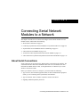
Cisco Connection Online
Cisco Connection Online (CCO) is Cisco Systems’ primary, real-time support channel.
Maintenance customers and partners can self-register on CCO to obtain additional
information and services.
Available 24 hours a day, 7 days a week, CCO provides a wealth of standard and valueadded services to Cisco’s customers and business partners. CCO services include product
information, product documentation, software updates, release notes, technical tips, the
Bug Navigator, configuration notes, brochures, descriptions of service offerings, and
download access to public and authorized files.
CCO serves a wide variety of users through two interfaces that are updated and enhanced
simultaneously: a character-based version and a multimedia version that resides on the
World Wide Web (WWW). The character-based CCO supports Zmodem, Kermit,
xiv
Cisco Network Modules Hardware Installation Guide
Ordering Documentation
Xmodem, FTP, and Internet e-mail, and it is excellent for quick access to information over
lower bandwidths. The WWW version of CCO provides richly formatted documents with
photographs, figures, graphics, and video, as well as hyperlinks to related information.
You can access CCO in the following ways:
•
•
•
•
•
WWW: http://www.cisco.com
WWW: http://www-europe.cisco.com
WWW: http://www-china.cisco.com
Telnet: cco.cisco.com
Modem: From North America, 408 526-8070; from Europe, 33 1 64 46 40 82. Use the
following terminal settings: VT100 emulation; databits: 8; parity: none; stop bits: 1; and
connection rates up to 28.8 kbps.
For a copy of CCO’s Frequently Asked Questions (FAQ), contact [email protected]. For
additional information, contact [email protected].
Note If you are a network administrator and need personal technical assistance with a
Cisco product that is under warranty or covered by a maintenance contract, contact Cisco’s
Technical Assistance Center (TAC) at 800 553-2447, 408 526-7209, or [email protected]. To
obtain general information about Cisco Systems, Cisco products, or upgrades, contact
800 553-6387, 408 526-7208, or [email protected].
Please use CCO to obtain general information about Cisco Systems, Cisco products, or
upgrades. If CCO is not accessible, contact 800 553-6387, 408 526-7208, or
[email protected].
Ordering Documentation
Cisco documentation and additional literature are available in a CD-ROM package, which
ships with your product. The Documentation CD-ROM, a member of the Cisco Connection
Family, is updated monthly. Therefore, it might be more current than printed
documentation. To order additional copies of the Documentation CD-ROM, contact your
local sales representative or call customer service. The CD-ROM package is available as a
About This Guide xv
Ordering Documentation
single package or as an annual subscription. You can also access Cisco documentation on
the World Wide Web at http://www.cisco.com, http://www-china.cisco.com,
or http://www-europe.cisco.com.
If you are reading Cisco product documentation on the World Wide Web, you can submit
comments electronically. Click Feedback in the toolbar and select Documentation. After
you complete the form, click Submit to send it to Cisco. We appreciate your comments.
xvi
Cisco Network Modules Hardware Installation Guide
C H A PT E R
1
Overview of Cisco Network
Modules
This chapter provides an overview of Cisco network modules used in Cisco modular access
routers. Cisco modular routers include:
•
•
Cisco 3600 Series Routers on page 1-1
Cisco 2600 Series Routers on page 1-7
Cisco 3600 Series Routers
Table 1-1 lists the network module options available for Cisco 3600 series routers with their
minimum software requirements for Cisco IOS Releases 11.1, 11.2, 11.3, and 11.3 T.
Table 1-1
Network Module Options with Cisco IOS Releases for Cisco 3600 Series Routers
Network Module
Cisco
Product Number
Cisco IOS
Release 11.1
Cisco IOS
Release 11.2
Cisco IOS
Release 11.3
Cisco IOS
Release 11.3 T
1-Port Ethernet
NM-1E
–
11.2(4)XA,
11.2(5)P
11.3(1)
11.3(1)T
1-Port Fast Ethernet TX
NM-1FE-TX
–
11.2(6)P
11.3(1)
11.3(1)T
1-Port Fast Ethernet FX
NM-1FE-FX
–
–
–
11.3(1)T
1-Port Fast Ethernet
1-Port or 2-Port
T1/ISDN1 PRI2
–
NM-1FE1CT1
NM-1FE1CT1-CSU
NM-1FE2CT1
NM-1FE2CT1-CSU
–
–
11.3(4)T
Overview of Cisco Network Modules 1-1
Cisco 3600 Series Routers
Table 1-1
Network Module Options with Cisco IOS Releases for Cisco 3600 Series Routers
Cisco
Product Number
Cisco IOS
Release 11.1
Cisco IOS
Release 11.2
Cisco IOS
Release 11.3
Cisco IOS
Release 11.3 T
1-Port Fast Ethernet
1-Port or 2-Port
E1/ISDN PRI
NM-1FE1CE1B
NM-1FE1CE1U
NM-1FE2CE1B
NM-1FE2CE1U
–
–
–
11.3(4)T
4-Port Ethernet
NM-4E
–
11.2(6)P
11.3(1)
11.3(1)T
1-Port Ethernet 2 WAN
card slots
NM-1E2W
11.1(7)AA
11.2(4)XA,
11.2(5)P
11.3(1)
11.3(1)T
2-Port Ethernet 2 WAN
card slots
NM-2E2W
11.1(7)AA
11.2(4)XA,
11.2(5)P
11.3(1)
11.3(1)T
1-Port Ethernet 1-Port
NM-1E1R2W
Token Ring 2 WAN card
slots
11.1(8)AA
11.2(4)XA,
11.2(5)P
11.3(1)
11.3(1)T
4-Port Serial
NM-4T
–
11.2(4)XA,
11.2(5)P
11.3(1)
11.3(1)T
4-Port/8-Port
Asynchronous/
Synchronous Serial
NM-4A/S
NM-8A/S
11.1(7)AA
11.2(4)XA,
11.2(5)P
11.3(1)
11.3(1)T
16-Port/32-Port
Asynchronous Serial
NM-16A
NM-32A
–
11.2(7a)P
11.3(1)
11.3(1)T
4-Port/8-Port ISDN
BRI3 S/T4
NM-4B-S/T
NM-8B-S/T
11.1(7)AA
11.2(4)XA,
11.2(5)P
11.3(1)
11.3(1)T
4-Port/8-Port ISDN
BRI5 with NT16
NM-4B-U
NM-8B-U
11.1(7)AA
11.2(4)XA,
11.2(5)P
11.3(1)
11.3(1)T
Network Module
1-2
Cisco Network Modules Hardware Installation Guide
Cisco 3600 Series Routers
Table 1-1
Network Module Options with Cisco IOS Releases for Cisco 3600 Series Routers
Cisco
Product Number
Cisco IOS
Release 11.1
Cisco IOS
Release 11.2
Cisco IOS
Release 11.3
Cisco IOS
Release 11.3 T
1-Port/2-Port
Channelized
T1/ISDN PRI
NM-1CT1
NM-2CT1
11.1(7)AA
11.2(4)XA,
11.2(5)P
11.3(1)
11.3(1)T
1-Port/2-Port
Channelized T1/ISDN
PRI with CSU7
NM-1CT1-CSU
NM-2CT1-CSU
11.1(7)AA
11.2(4)XA,
11.2(5)P
11.3(1)
11.3(1)T
1-Port/2Port
Channelized E1/ISDN
PRI Unbalanced
NM-1CE1U
NM-2CE1U
11.1(7)AA
11.2(4)XA,
11.2(5)P
11.3(1)
11.3(1)T
1-Port/2-Port
Channelized
E1/ISDN PRI Balanced
NM-1CE1B
NM-2CE1B
11.1(7)AA
11.2(4)XA,
11.2(5)P
11.3(1)
11.3(1)T
1-Port/2-Port Voice
NM-1V
NM-2V
–
–
–
11.3(1)T
6-Port/12-Port/18-Port/
24-Port/30-Port Digital
Modem
NM-6DM
NM-12DM
NM-18DM
NM-24DM
NM-30DM
–
11.2(9)XA
11.2(10)P
–
11.3(2)T
8-Port and 16-Port
Analog Modem
NM-8AM
NM-16AM
–
–
–
11.3(4)T
1-Port ATM8-25
NM-1ATM-25
–
–
–
11.3(3a)T
Network Module
Overview of Cisco Network Modules 1-3
Cisco 3600 Series Routers
Table 1-1
Network Module Options with Cisco IOS Releases for Cisco 3600 Series Routers
Network Module
Cisco
Product Number
Cisco IOS
Release 11.1
Cisco IOS
Release 11.2
Cisco IOS
Release 11.3
Cisco IOS
Release 11.3 T
1-Port HSSI9
NM-1HSSI
–
–
–
11.3(3)T
Compression
NM-COMPR
–
11.2(7a)P
11.3(1)
11.3(1)T
1
2
3
4
5
6
7
8
9
ISDN = Integrated Services Digital Network.
PRI = Primary Rate Interface.
BRI = Basic Rate Interface.
The BRI S/T module requires an external NT1.
The BRI U module does not require an external NT1.
NT1 = Network Termination 1.
CSU = channel service unit.
ATM = Asynchronous Transfer Mode.
HSSI = High-Speed Serial Interface.
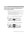
Cisco 3600 Series Interface Numbering
Each individual network interface on a Cisco 3600 series router is identified by a slot
number and a unit number.
Slot Numbering
The Cisco 3600 series router chassis contains two or four slots in which you can install
modules. You can install any module into any available slot in the chassis.
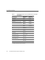
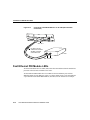
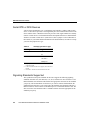
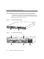
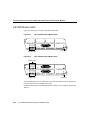
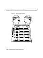
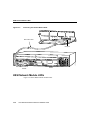
As shown in Figure 1-1, the slots are numbered from 0 to 3, as follows:
1-4
•
Slot 0 is at the bottom right (as viewed from the rear of the chassis), near the power
supply.
•
•
•
Slot 1 is at the bottom left.
Slot 2 is at the top right, above slot 0.
Slot 3 is at the top left, above slot 1.
Cisco Network Modules Hardware Installation Guide
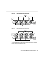
Cisco 3600 Series Interface Numbering
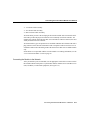
Figure 1-1
Cisco 3600 Series Module Card Slots
Slot 2
Slot 3
2
BRI
NT1
WO 2E W1
DO NOT INSTALL WAN INTERFACE
CARDS WITH POWER APPLIED
2W
SERIAL
ETHERNET 1
ACT
ACT
ETHERNET 0
LNK
STP
AUI
EN
LNK
LNK
ACT
SERIAL
ETHERNET 1
AUI
EN
ETHERNET 0
INPUT 100-240VAC 50/60HZ 3.0-1.5 AMPS
Slot 1
Slot 0
Power supply
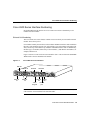
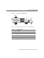
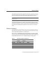
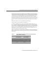
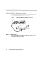
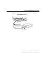
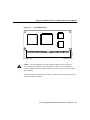
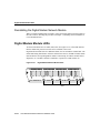
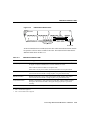
Some modules have two small slots, labeled W0 and W1, for WAN interface cards.
Figure 1-2 shows the W0 and W1 slots of the 2 Ethernet 2 WAN card slot
(2E 2-slot) module. You can install WAN interface cards into the small module slots (W0
and W1). Serial WAN interface cards can be installed into either slot, W0 or W1.
WAN Interface Card Slots
ETHERNET 1
Slot W0
WO
AUI
EN
LNK
ACT
STP
ILNK
Slot W1
2E
2W W1
ETHERNET 0
H8603
Figure 1-2
ACT
1
LNK
ACT
SEE MANUAL BEFORE INSTALLATION
H6551
B2
ACT
B1
ACT
2E
W1
2W
NT1
3
Overview of Cisco Network Modules 1-5
Cisco 3600 Series Routers
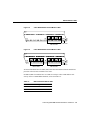
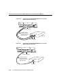
Unit Numbering
Cisco 3600 series routers unit numbers identify the interfaces on the modules and WAN
interface cards installed in the router. Unit numbers begin at 0 for each interface type, and
continue from right to left and (if necessary) from bottom to top. Modules and WAN
interface cards are identified by interface type, slot number, followed by a forward slash
(/), and then the unit number; for example, Ethernet 0/0.
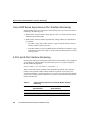
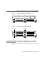
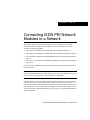
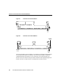
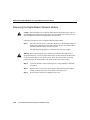
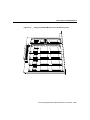
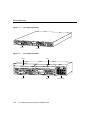
Figure 1-3 shows a router with a 2E 2-slot module in slots 0 and 1. Two serial WAN
interface cards are installed in the module in slot 0. One serial and one ISDN BRI WAN
interface card are installed in the module in slot 1.
Figure 1-3
Cisco 3600 Series Unit Numbers
BRI 1/0
Serial 1/0
Serial 0/1
Serial 0/0
2
WO 2E W1
2W
ACT
BRI
NT1
SERIAL
ETHERNET 1
ETHERNET 0
ETHERNET 1
ACT
LNK
STP
LNK
LNK
ACT
SERIAL
AUI
EN
ACT
1
LNK
ACT
SEE MANUAL BEFORE INSTALLATION
H8604
B2
ACT
B1
ACT
2E
W1
2W
NT1
3
AUI
EN
ETHERNET 0
INPUT 100-240VAC 50/60HZ 3.0-1.5 AMPS
Ethernet 1/1
Ethernet 1/0
Ethernet 0/1
Ethernet 0/0
As shown in Figure 1-3, the unit numbers are as follows:
•
•
•
•
•
•
1-6
Slot 0, Ethernet interface 0, referred to as Ethernet 0/0
Slot 0, Ethernet interface 1, referred to as Ethernet 0/1
Slot 0, serial interface 0, referred to as serial 0/0
Slot 0, serial interface 1, referred to as serial 0/1
Slot 1, Ethernet interface 0, referred to as Ethernet 1/0
Slot 1, Ethernet interface 1, referred to as Ethernet 1/1
Cisco Network Modules Hardware Installation Guide
Power supply
Cisco 2600 Series Routers
•
•
Slot 1, serial interface 0, referred to as serial 1/0
Slot 1, BRI interface 0, referred to as BRI 1/0
Note The 2E 2-slot module described in this example provides both an attachment unit
interface (AUI) and 10BaseT port. Only one of these ports can be used at a time. The
module automatically detects which port, AUI or 10BaseT, is in use.
Voice Interface Numbering in Cisco 3600 Series Routers
Voice interfaces are numbered differently from WAN interfaces described in the previous
section, “Unit Numbering.” Voice interfaces are numbered as follows:
interface type chassis slot/voice module slot/voice interface
If you have a four-channel voice network module installed in slot 1 of your router, the voice
interfaces will be:
•
Slot 1, voice network module slot 0, voice interface 0, referred to as voice 1/0/0 (closest
to chassis slot 0)
•
•
•
Slot 1, voice network module slot 0, voice interface 1, referred to as voice 1/0/1
Slot 1, voice network module slot 1, voice interface 0, referred to as voice 1/1/0
Slot 1, voice network module slot 1, voice interface 1, referred to as voice 1/1/1 (farthest
from chassis slot 0)
Cisco 2600 Series Routers
Table 1-2 lists the network module options available for Cisco 2600 series routers with their
minimum software requirements for Cisco IOS Release 11.3 and 11.3 T.
Overview of Cisco Network Modules 1-7
Cisco 2600 Series Routers
Table 1-2
Network Module
Cisco Product
Number
Cisco IOS
Release 11.3 T
1-Port Ethernet
NM-1E
11.3(4)T
4-Port Ethernet
NM-4E
11.3(4)T
4-Port/8-Port
Asynchronous/Synchronous Serial
NM-4A/S
NM-8A/S
11.3(3)T,
11.3(2) XA
16-Port/32-Port Asynchronous Serial
NM-16A
NM-32A
11.3(3)T,
11.3(2) XA
1-Port/2-Port Voice
NM-1V
NM-2V
11.3(3)T,
11.3(2) XA
4-Port/8-Port ISDN BRI
S/T1
NM-4B-S/T
NM-8B-S/T
11.3(4)T
4-Port/8-Port ISDN BRI2 with NT1
NM-4B-U
NM-8B-U
11.3(4)T
1-Port/2-Port Channelized
T1/ISDN PRI
NM-1CT1
NM-2CT1
11.3(4)T
1-Port/2-Port Channelized
T1/ISDN PRI with CSU
NM-1CT1-CSU
NM-2CT1-CSU
11.3(4)T
1-Port/2Port Channelized
E1/ISDN PRI Unbalanced
NM-1CE1U
NM-2CE1U
11.3(4)T
1-Port/2-Port Channelized
E1/ISDN PRI Balanced
NM-1CE1B
NM-2CE1B
11.3(4)T
8-Port and 16-Port Analog Modem
NM-8AM
NM-16AM
11.3(4)T
1-Port ATM-25
NM-1ATM-25
11.3(4)T
1
2
1-8
Network Module Options with Cisco IOS Releases for Cisco 2600
Series Routers
The BRI S/T module requires an external NT1.
The BRI U module does not require an external NT1.
Cisco Network Modules Hardware Installation Guide
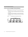
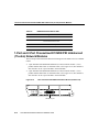
Cisco 2600 Series Interface Numbering
Cisco 2600 Series Interface Numbering
Each individual network interface on a Cisco 2600 series router is identified by a slot
number and a unit number.
Slot and Unit Numbering
The Cisco 2600 series router chassis contains one slot in which you can install a network
module. This is always slot 1.
Unit numbers identify the interfaces on the modules and WAN interface cards installed in
the router. Unit numbers begin at 0 for each interface type, and continue from right to left
and (if necessary) from bottom to top. Modules and WAN interface cards are identified by
interface type, slot number, followed by a forward slash (/), and then the unit number; for
example, Ethernet 0/0.
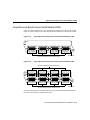
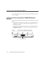
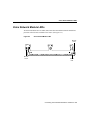
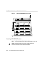
Figure 1-4 shows a router with a 2E 2-slot module in slot 1. One serial and one ISDN BRI
WAN interface card are installed in the module.
Figure 1-4
Cisco 2600 Series Unit Numbers
BRI 1/0
Serial 0/1
BRI
NT1
B2
Serial 0/0
WO
Cisco 2612
SERIAL
SEE MANUAL BEFORE INSTALLATION
CONN
LNK
ACT
ACT
LNK
AUI
EN
W1
SERIAL
W0
W0
ETHERNET 0
LINK TOKEN RING 0/0 ACT LINK
ETHERNET 0/0 ACT CONSOLE
Ethernet
1/1
100-240V– 1A
50/60 Hz 47 W
SERIAL
CONN
ETHERNET 1
16552
B1
ACT
NT1
Serial 1/0
2E
W1
2W
Ethernet
1/0
AUX
Ethernet Auxiliary
port
0/0
Token
Console
Ring 0/0
port
Note WAN interface card slots (built into the chassis) are always numbered as slot 0, even
if the interface card is installed in the slot labeled W1.
Overview of Cisco Network Modules 1-9
Cisco 2600 Series Routers
Figure 1-4 shows the following unit numbers:
•
•
•
•
•
•
•
•
First Ethernet interface, referred to as Ethernet 0/0
Token ring interface, referred to as Token Ring 0/0
Slot W0, serial interface 0, referred to as serial 0/0
Slot W1, serial interface 1, referred to as serial 0/1
Slot 1, Ethernet interface 0, referred to as Ethernet 1/0
Slot 1, Ethernet interface 1, referred to as Ethernet 1/1
Slot 1, serial interface 0, referred to as serial 1/0
Slot 1, BRI interface 0, referred to BRI 1/0
Note The 2E 2-slot module described in this example provides both an attachment unit
interface (AUI) and 10BaseT port. Only one of these ports can be used at a time. The
module automatically detects which port, AUI or 10BaseT, is in use.
Voice Interface Numbering in Cisco 2600 Series Routers
Voice interfaces are numbered differently from WAN interfaces described in the previous
section, “Slot and Unit Numbering.” Voice interfaces are numbered as follows:
interface type chassis slot/voice module slot/voice interface
If you have a four-channel voice network module installed in slot 1 of your router, the voice
interfaces will be:
1-10
•
Slot 1, voice network module slot 0, voice interface 0, referred to as voice 1/0/0 (closest
to the chassis WAN interface card slots)
•
•
•
Slot 1, voice network module slot 0, voice interface 1, referred to as voice 1/0/1
Slot 1, voice network module slot 1, voice interface 0, referred to as voice 1/1/0
Slot 1, voice network module slot 1, voice interface 1, referred to as voice 1/1/1 (farthest
from the chassis WAN interface card slots)
Cisco Network Modules Hardware Installation Guide
C H A PT E R
2
Preparing to Install Network
Modules
This chapter describes important information to consider before you begin to install
network modules in Cisco modular routers, and includes the following sections:
•
•
Safety Information on page 2-1
Required Tools and Equipment on page 2-4
Safety Information
This section contains safety warnings that you should be aware of before installing a
network module in the router.
Safety Recommendations
Follow these guidelines to ensure general safety:
•
•
•
•
Keep the chassis area clear and dust-free during and after installation.
•
Wear safety glasses when working under any conditions that might be hazardous to your
eyes.
•
Do not perform any action that creates a potential hazard to people or makes equipment
unsafe.
Put the removed chassis cover in a safe place.
Keep tools away from walk areas where you or others could fall over them.
Do not wear loose clothing that could get caught in the chassis. Fasten your tie or scarf
and roll up your sleeves.
Preparing to Install Network Modules 2-1
Safety Information
Safety Warnings
Safety warnings appear throughout this publication in procedures that, if performed
incorrectly, may harm you. A warning symbol precedes each warning statement.
Safety with Electricity
Warning Before working on equipment that is connected to power lines, remove jewelry
(including rings, necklaces, and watches). Metal objects will heat up when connected to
power and ground and can cause serious burns or weld the metal object to the terminals.
Warning To avoid electric shock, do not connect safety extra-low voltage (SELV)
circuits to telephone-network voltage (TNV) circuits. LAN ports contain SELV circuits,
and WAN ports contain TNV circuits. Both LAN and WAN ports may use RJ-45
connectors. Use caution when connecting cables.
Warning Hazardous network voltages are present in WAN ports regardless of whether
power to the router is OFF or ON. To avoid electric shock, use caution when working near
WAN ports. When detaching cables, detach the end away from the router first.
Warning Before opening the chassis, disconnect the telephone-network cables to avoid
contact with telephone-network voltages.
Warning Do not work on the system or connect or disconnect cables during periods of
lightning activity.
Warning Do not touch the power supply when the power cord is connected. For systems
with a power switch, line voltages are present within the power supply even when the
power switch is OFF and the power cord is connected. For systems without a power
switch, line voltages are present within the power supply when the power cord is
connected.
2-2
Cisco Network Modules Hardware Installation Guide
Preventing Electrostatic Discharge Damage
Follow these guidelines when working on equipment powered by electricity:
•
Locate the emergency power-off switch in the room in which you are working. Then, if
an electrical accident occurs, you can quickly shut the power OFF.
•
•
Before working on the router, turn OFF the power and unplug the power cord.
Disconnect all power before doing the following:
— Installing or removing a router chassis
— Working near power supplies
•
•
•
Do not work alone if potentially hazardous conditions exist.
•
If an electrical accident occurs, proceed as follows:
Never assume that power is disconnected from a circuit. Always check.
Look carefully for possible hazards in your work area, such as moist floors, ungrounded
power extension cables, and missing safety grounds.
— Use caution; do not become a victim yourself.
— Turn OFF power to the router.
— If possible, send another person to get medical aid. Otherwise, determine the
condition of the victim and then call for help.
— Determine if the person needs rescue breathing or external cardiac compressions;
then take appropriate action.
Preventing Electrostatic Discharge Damage
Electrostatic discharge (ESD) can damage equipment and impair electrical circuitry. It
occurs when electronic printed circuit cards are improperly handled and can result in
complete or intermittent failures. Always follow ESD prevention procedures when
removing and replacing cards. Ensure that the router chassis is electrically connected to
earth ground. Wear an ESD-preventive wrist strap, ensuring that it makes good skin contact.
Connect the clip to an unpainted surface of the chassis frame to safely channel unwanted
Preparing to Install Network Modules 2-3
Required Tools and Equipment
ESD voltages to ground. To properly guard against ESD damage and shocks, the wrist strap
and cord must operate effectively. If no wrist strap is available, ground yourself by touching
the metal part of the chassis.
Caution For safety, periodically check the resistance value of the antistatic strap, which
should be between 1 and 10 megohm (Mohm).
Required Tools and Equipment
You need the following tools and equipment to install a network module in a Cisco modular
router chassis slot:
•
•
2-4
Number 1 Phillips screwdriver or small flat-blade screwdriver
ESD-preventive wrist strap
Cisco Network Modules Hardware Installation Guide
C H A PT E R
3
Installing Network Modules in
Cisco Modular Routers
This chapter describes how to install network modules in Cisco modular routers, and
includes the following sections:
•
•
Installing a Network Module in a Modular Router Chassis Slot on page 3-1
Installing a WAN Interface Card in a Network Module Slot on page 3-3
Installing a Network Module in a Modular Router Chassis
Slot
Caution Network modules do not support online insertion and removal (hot swap). To
avoid damaging the module, before you insert a network module into a chassis slot, you
must turn OFF electrical power and disconnect network cables.
The following instructions apply only to installing network modules in a modular router
chassis slot. To install a WAN interface card in a network module, see the “Installing a
WAN Interface Card in a Network Module Slot” section on page 3-3.
You can install network modules in the chassis either before or after mounting the router,
whichever is more convenient.
Follow this procedure to install a network module:
Step 1
Turn OFF electrical power to the router. However, to channel electrostatic
discharge (ESD) voltages to ground, do not unplug the power cable. Remove all
network interface cables, including telephone cables, from the rear panel.
Installing Network Modules in Cisco Modular Routers 3-1
Installing a Network Module in a Modular Router Chassis Slot
The following warning applies to routers that use a DC power supply:
Warning Before performing any of the following procedures, ensure that power is
removed from the DC circuit. To ensure that all power is OFF, locate the circuit breaker
on the panel board that services the DC circuit, switch the circuit breaker to the OFF
position, and tape the switch handle of the circuit breaker in the OFF position.
Using either a number 1 Phillips screwdriver or a small flat-blade screwdriver,
remove the blank filler panel from the chassis slot where you plan to install the
module. Save the blank panel for future use.
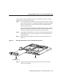
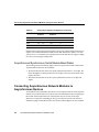
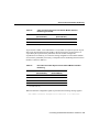
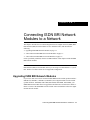
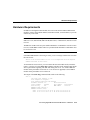
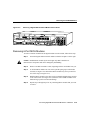
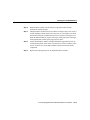
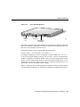
Step 3
Align the network module with the guides in the chassis and slide it gently into
the slot. (See Figure 3-1.)
Installing a Network Module in a Modular Router (Typical)
ACT
Figure 3-1
Step 2
WO
H9998
SERIAL
ASYNC
ETHERNET 0
15
11
14
10
13
9
12
8
15
11
14
10
13
9
12
8
ASYNC 24-31
ASYNC 8-15
7
3
6
2
5
1
4
0
7
3
6
2
5
1
4
0
ASYNC 16-23
ASYNC 0-7
EN
Asynchronous network module
3-2
Router
Step 4
Push the module into place until you feel its edge connector mate securely with
the connector on the motherboard.
Step 5
Fasten the module’s captive mounting screws into the holes in the chassis, using
the Phillips or flat-blade screwdriver.
Step 6
If the router was previously running, reinstall the network interface cables and
turn ON power to the router.
Cisco Network Modules Hardware Installation Guide
Blank Network Module Panels
The following warning applies to routers that use a DC power supply:
Warning After wiring the DC power supply, remove the tape from the circuit breaker
switch handle and reinstate power by moving the handle of the circuit breaker to the ON
position.
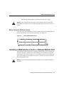
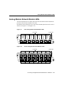
Blank Network Module Panels
If the router is not fully configured with network modules, make sure that blank panels fill
the unoccupied chassis slots to provide proper airflow. (See Figure 3-2.)
Blank Network Module Panel
H6552
Figure 3-2
Installing a WAN Interface Card in a Network Module Slot
The following instructions apply only to installing a WAN interface card in a module slot.
To install a module in a chassis slot, see the “Installing a Network Module in a Modular
Router Chassis Slot” section on page 3-1. To see translated versions of the warnings that
appear in this chapter, see the Regulatory Compliance and Safety Information document
that accompanied the router.
Warning Only trained and qualified personnel should be allowed to install or replace this
equipment.
Installing Network Modules in Cisco Modular Routers 3-3
Installing a WAN Interface Card in a Network Module Slot
Warning Do not insert a WAN interface card into a base module slot while power is ON
or network cables are connected.
Warning Before opening the chassis, disconnect the telephone-network cables to avoid
contact with telephone-network voltages.
Warning Do not work on the system or connect or disconnect cables during periods of
lightning activity.
Warning To avoid electric shock, do not insert a WAN interface card into a two-slot
module while power is ON or network cables are connected.
Note A WAN interface card can be installed in a module that is already installed in a
router. Before inserting a WAN interface card into a base module that is already installed
in the router chassis, you must turn OFF electrical power.
Note Do not install an Integrated Services Digital Network (ISDN) Basic Rate Interface
(BRI) WAN interface card or an ISDN BRI network module in the same chassis as an ISDN
Primary Rate Interface (PRI) network module, unless you are using Cisco IOS
Release 11.3(3)T or later. Earlier releases of Cisco IOS software do not support this
configuration.
Note Do not install a newer BRI WAN interface card in the same network module as an
older BRI WAN interface card. The easiest way to identify the newer and older cards is to
observe the LED placement: on the newer card, the B-channel LEDs are arranged
horizontally and on the older card, the B-channel LEDs are arranged vertically.
3-4
Cisco Network Modules Hardware Installation Guide
Installing a WAN Interface Card in a Network Module Slot
You need either a number 1 Phillips screwdriver or a flat-blade screwdriver. To install a
WAN interface card, follow this procedure:
If you are installing the card directly into a base module in the router, turn OFF
power to the router. However, to channel ESD voltages to ground, do not unplug
the power cable. Remove all network interface cables, including telephone
cables, from the rear panel.
Step 1
If you are installing the card into the base module outside the router, attach an
ESD-preventive wrist strap and ensure that it makes good contact with your skin.
Connect the equipment end of the wrist strap to an electrical ground.
Figure 3-3
Step 2
Using a Phillips or flat-blade screwdriver, remove the blank filler panel from the
base module slot where you plan to install the card. Save the filler panel for
possible future use.
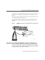
Step 3
Align the card with the guides in the module slot and slide it gently in. (See
Figure 3-3.)
Installing a WAN Interface Card in a Network Module (Typical)
ACT
LNK
ACT
LNK
WO
ETH 1
AUI
EN
ETHERN
ET 0
B1
H7219
2E
2W W1
B2
BRI
S/T
Module
BRI S/T
WAN interface card
Step 4
Push the card into place until the edge connector is securely seated in the
connector on the module.
Installing Network Modules in Cisco Modular Routers 3-5
Installing a WAN Interface Card in a Network Module Slot
Step 5
Secure the captive mounting screws into the holes of the module faceplate, using
a Phillips or flat-blade screwdriver.
Step 6
If the router was previously running, reinstall the network interface cables and
power ON the router.
WAN Interface Card Filler Panels
If the base module is configured with only one WAN interface card, secure a slot filler panel
into the open base module slot to ensure proper airflow. (See Figure 3-4.)
Figure 3-4
WAN Interface Card Slot Filler Panel
H6649
DO NOT INSTALL WAN INTERFACE
CARDS WITH POWER APPLIED
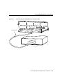
After installing any WAN interface cards you may have, if you need assistance in installing
a network module in your router, see the “Installing a Network Module in a Modular Router
Chassis Slot” section on page 3-1.
The next chapters in this guide contain connection and LED information for Cisco network
modules. Proceed to the chapter that corresponds to your type of network module:
•
•
•
•
•
•
•
•
3-6
Chapter 4, “Connecting Ethernet Network Modules to a Network”
Chapter 5, “Connecting Fast Ethernet PRI Network Modules to a Network”
Chapter 6, “Connecting Serial Network Modules to a Network”
Chapter 7, “Connecting ISDN BRI Network Modules to a Network”
Chapter 8, “Connecting ISDN PRI Network Modules to a Network”
Chapter 9, “Connecting Voice Network Modules to a Network”
Chapter 10, “Connecting Digital Modem Network Modules to a Network”
Chapter 11,“Connecting Analog Modem Network Modules to a Network”
Cisco Network Modules Hardware Installation Guide
WAN Interface Card Filler Panels
•
•
•
Chapter 12, “Connecting ATM Network Modules to a Network”
Chapter 13, “Connecting HSSI Network Modules to a Network”
Chapter 14, “Connecting Compression Network Modules to a Network”
Installing Network Modules in Cisco Modular Routers 3-7
Installing a WAN Interface Card in a Network Module Slot
3-8
Cisco Network Modules Hardware Installation Guide
4
C H A PT E R
Connecting Ethernet Network
Modules to a Network
This chapter describes how to connect and configure Ethernet network modules in Cisco
modular routers, and describes the following modules:
•
•
1-Port and 4-Port Ethernet Modules on page 4-1
1-Port Fast Ethernet Module on page 4-5
1-Port and 4-Port Ethernet Modules
This section provides information about the following network modules for Cisco modular
routers:
•
•
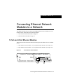
1-port Ethernet network module—(Cisco product number NM-1E). (See Figure 4-1.)
4-port Ethernet network module—(Cisco product number NM-4E). (See Figure 4-2.)
Figure 4-1
1-Port Ethernet Network Module
ETHERNET
1E
ETH 0
EN
ACT
10BaseT
port
H9251
LINK
AUI
port
Connecting Ethernet Network Modules to a Network 4-1
1-Port and 4-Port Ethernet Modules
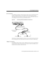
Figure 4-2
4-Port Ethernet Network Module
ETHERNET
4E
ETH 3
ETH 2
ETH 0
ETH 1
0
3 2 1
LINK
EN
H9252
ACT
10BaseT
port
AUI
port
Ethernet Network Module Connectors
The 1-port Ethernet network module has a single port (Ethernet port 0) for one Ethernet
connection. The 4-port Ethernet network module has ports for four Ethernet connections.
(See Figure 4-2.) Ethernet port 0 uses either the attachment unit interface (AUI) (DB-15)
connector on the right side of the module or the 10BaseT (RJ-45) connector next to it. Only
one of these connectors can be active at a time. Ethernet ports 1, 2, and 3 on the 4-port
Ethernet module use 10BaseT connectors. These ports do not provide an AUI connector.
Active ports are identified in software by port type (Ethernet), the module’s slot number,
and the port number.
On port 0, the module detects the type of network connection automatically, and you do not
need to select the media type when you configure the software. If cables are plugged into
both the AUI connector and the 10BaseT connector for the same port, the 10BaseT
connection is selected.
Connecting Ethernet Ports
On Ethernet port 0 (the right port), you can connect either the Ethernet AUI connector or
the 10BaseT connector, but not both at the same time. Ports 1, 2, and 3 provide only a
10BaseT connector.
4-2
Cisco Network Modules Hardware Installation Guide
Connecting Ethernet Ports
AUI Connections
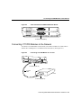
Use an Ethernet AUI cable to connect the AUI port on the 1-port or 4-port Ethernet network
module to an Ethernet transceiver. The female end of the AUI cable mates with the
slide-latch connector of the transceiver cable. Figure 4-3 shows a thin Ethernet transceiver
as an example, but you can use any type of Ethernet transceiver.
Figure 4-3
Connecting an Ethernet AUI Port to a Transceiver
ETHERNET
4E
ETH 3
ETH 2
ETH 1
ETH 0
3 2 1
0
LINK
EN
ACT
Ethernet AUI port (DB-15)
(with jackscrews or slide-latch)
Ethernet AUI cable
(not supplied)
Ethernet
transceiver
H9255
BNC connector
To thin Ethernet network
To thin Ethernet network
If the transceiver cable has thumbscrew connectors, you can connect it directly to the AUI
port by replacing the AUI port slide latch with a jackscrew (provided in a separate bag).
10BaseT Connections
Use an Ethernet 10BaseT cable to connect a 10BaseT port on the 1-port or 4-port Ethernet
network module to a hub or other network device. Figure 4-4 shows the 10BaseT port on
an Ethernet network module connected to a hub.
Connecting Ethernet Network Modules to a Network 4-3
1-Port and 4-Port Ethernet Modules
Figure 4-4
Connecting an Ethernet 10BaseT Port to a Hub
ETHERNET
4E
ETH 3
ETH 2
ETH 1
ETH 0
3 2 1
0
LINK
EN
ACT
Ethernet 10BaseT
port (RJ-45)
H9256
10BaseT cable
10BaseT hub
1-Port and 4-Port Ethernet Network Module LEDs
This section describes the LEDs for the 1-port and 4-port Ethernet network module.
Figure 4-5 shows the 4-port Ethernet network module’s LEDs, however these apply to the
1-port Ethernet network module as well.
All network modules have an enable (EN) LED. The enable LED indicates that the module
has passed its self-tests and is available to the router.
Each Ethernet port has two LEDs. The activity (ACT) LED indicates that the router is
sending or receiving Ethernet transmissions. The link (LINK) LED indicates that the
Ethernet port is receiving the link integrity signal from the hub (10BaseT only).
4-4
Cisco Network Modules Hardware Installation Guide
1-Port Fast Ethernet Module
Figure 4-5
Ethernet Network Module LEDs (Typical)
ETHERNET
4E
ETH 3
ETH 2
ETH 0
ETH 1
0
3 2 1
LINK
LEDs
EN
H9254
ACT
Enable
LED
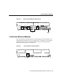
1-Port Fast Ethernet Module
This section provides information about the 1-port Fast Ethernet network module (Cisco
product number NM-1FE-TX) for Cisco modular routers. (See Figure 4-6.) This module
enables the router to connect to 100-Mbps Ethernet networks and create high-speed
communication links between network devices.
Figure 4-6
1-Port Fast Ethernet Network Module
FAST ETHERNET
1FE
EN
H9981
FULL
DPLX
100
MBPS
LINK
C0L
10/100 bTX
RJ-45 port
Connecting Ethernet Network Modules to a Network 4-5
1-Port Fast Ethernet Module
Connecting Fast Ethernet Ports
Use a two-pair Category 5 or unshielded twisted-pair (UTP) straight-through RJ-45 cable
to connect the RJ-45 port on a 1-port Fast Ethernet network module to a switch, hub,
repeater, server, or other network device. Figure 4-7 shows the RJ-45 port connected to a
hub.
Note RJ-45 cables are not available from Cisco Systems. These cables are widely
available and must be Category 5 cables.
Figure 4-7
Connecting a Fast Ethernet RJ-45 Port to a Hub
FE–PRI
COLL
LINK
EN
Fast Ethernet
RJ-45
H9984
Category 5
or UTP cable
FDX
10/100BaseT
CTRLR 0
100Mbps
CARRIER
DETECT
REMOTE
ALARM
LOCAL
ALARM
LOOP
BACK
1FE-1CT1
Fast Ethernet hub
4-6
Cisco Network Modules Hardware Installation Guide
1-Port Fast Ethernet Network Module LEDs
1-Port Fast Ethernet Network Module LEDs
Figure 4-8 shows the 1-port Fast Ethernet network module’s LEDs.
Figure 4-8
1-Port Fast Ethernet Network Module LEDs
FAST ETHERNET
1FE
EN
H9982
FULL
DPLX
100
MBPS
LINK
COL
10/100 bTX
LEDs
Enable
LED
All network modules have an enable (EN) LED. The enable LED indicates that the module
has passed its self-tests and is available to the router.
The 1-port Fast Ethernet network module has the additional LEDs shown in Table 4-1.
Table 4-1
Fast Ethernet Network Module LEDs
LED
Meaning
COL
Collision activity is occurring on the
network
LINK
A link has been established with the station
at the other end of the cable
100MBPS
Speed of the interface is 100 Mbps
FULL DPLX
Interface is in full-duplex mode
Connecting Ethernet Network Modules to a Network 4-7
1-Port Fast Ethernet Module
4-8
Cisco Network Modules Hardware Installation Guide
C H A PT E R
5
Connecting Fast Ethernet PRI
Network Modules to a Network
Note Fast Ethernet network modules are supported in Cisco 3600 series routers only.
This chapter describes how to connect Fast Ethernet-Integrated Services Digital Network
(ISDN) Primary Rate Interface (PRI) network modules in Cisco 3600 series routers, and
describes the following modules:
•
1-Port Fast Ethernet and 1-Port or 2-Port Channelized T1/ISDN PRI Network Modules
on page 5-2
•
1-Port Fast Ethernet and 1-Port or 2-Port Channelized T1/ISDN PRI with CSU Network
Modules on page 5-5
•
1-Port Fast Ethernet and 1-Port Channelized E1/ISDN PRI Balanced (120-ohm) or
Unbalanced (75-ohm) Network Modules on page 5-7
•
1-Port Fast Ethernet and 2-Port Channelized E1/ISDN PRI Balanced (120-ohm) or
Unbalanced (75-ohm) Network Modules on page 5-8
•
Fast Ethernet PRI Module LEDs on page 5-12
Note These network modules provide ports for connection both to a 10- or 100-Mbps
Ethernet LAN and to an ISDN PRI LAN.
Note Unless specifically identified, references to Fast Ethernet PRI network modules in
this chapter include all these network modules.
Connecting Fast Ethernet PRI Network Modules to a Network 5-1
1-Port Fast Ethernet and 1-Port or 2-Port Channelized T1/ISDN PRI Network Modules
1-Port Fast Ethernet and 1-Port or 2-Port Channelized
T1/ISDN PRI Network Modules
This section provides information about the following network modules for Cisco 3600
series modular routers.
•
1-port Fast Ethernet 1-port channelized T1/ISDN PRI network module—Cisco product
number NM-1FE1CT1. (See Figure 5-1.)
•
1-port Fast Ethernet 2-port channelized T1/ISDN PRI network module—Cisco product
number NM-1FE2CT1. (See Figure 5-2.)
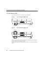
Figure 5-1
1-Port Fast Ethernet 1-Port Channelized T1 Network Module
FE–PRI
1FE-1CT1
15228
FDX
100Mbps
LINK
COLL
CARRIER
DETECT
CTRLR 1
CARRIER
DETECT
LOOP
BACK
1FE-2CT1
EN
1-Port Fast Ethernet 2-Port Channelized T1 Network Module
LOCAL
ALARM
FE-PRI
REMOTE
ALARM
Figure 5-2
CARRIER
DETECT
LOOP
BACK
LOCAL
ALARM
REMOTE
ALARM
10/100BaseT
CTRLR 0
CTRLR 0
5-2
Cisco Network Modules Hardware Installation Guide
EN
10976
FDX
100Mbps
LINK
COLL
LOOP
BACK
LOCAL
ALARM
REMOTE
ALARM
10/100BaseT
Connecting Fast Ethernet Channelized T1 Modules to the Network
Connecting Fast Ethernet Channelized T1 Modules to the
Network
In order to connect Fast Ethernet channelized T1 modules to the network, complete the
following:
•
•
Connecting the Fast Ethernet Port on page 5-3
Connecting the PRI Ports on page 5-4
Connecting the Fast Ethernet Port
Use a straight-through two-pair Category 5 unshielded twisted-pair (UTP) cable to connect
the RJ-45 port on the Fast Ethernet PRI network module to a switch, hub, repeater, server,
or other network device. These ports are color-coded yellow. Figure 5-3 shows the RJ-45
port connected to a hub.
Note RJ-45 cables are not available from Cisco Systems. These cables are widely
available and must be Category 5 cables.
Connecting Fast Ethernet PRI Network Modules to a Network 5-3
1-Port Fast Ethernet and 1-Port or 2-Port Channelized T1/ISDN PRI Network Modules
Figure 5-3
Connecting a Fast Ethernet RJ-45 Port to a Hub
FE–PRI
COLL
LINK
EN
Fast Ethernet
RJ-45
H9984
Category 5
or UTP cable
FDX
10/100BaseT
CTRLR 0
100Mbps
CARRIER
DETECT
REMOTE
ALARM
LOCAL
ALARM
LOOP
BACK
1FE-1CT1
Fast Ethernet hub
Connecting the PRI Ports
This section describes how to connect channelized T1 and channelized E1 ISDN PRI ports
to the network. These ports are color-coded tan.
Use a DB-15-to-DB-15 T1 serial cable to connect a CT1/PRI port to a T1 channel service
unit (CSU). (See Figure 5-4.)
5-4
Cisco Network Modules Hardware Installation Guide
1-Port Fast Ethernet and 1-Port or 2-Port Channelized T1/ISDN PRI with CSU Network Modules
Figure 5-4
Connecting a CT1/PRI Port to a T1 CSU
FE–PRI
100Mbps
COLL
FDX
10/100BaseT
CTRLR 0
LINK
CARRIER
DETECT
REMOTE
ALARM
LOCAL
ALARM
LOOP
BACK
1FE-1CT1
EN
H7468
CT1/PRI port (DB-15)
T1 serial
cable
T1 CSU
CT1/PRI port (DB-15)
1-Port Fast Ethernet and 1-Port or 2-Port Channelized
T1/ISDN PRI with CSU Network Modules
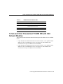
This section provides information about the following network modules for Cisco 3600
series modular routers:
•
1-port Fast Ethernet 1-port channelized T1/ISDN PRI with CSU network
module—Cisco product number NM-1FE1CT1-CSU. (See Figure 5-5.)
•
1-port Fast Ethernet 2-port channelized T1/ISDN PRI with CSU network
module—Cisco product number NM-1FE2CT1-CSU. (See Figure 5-6.)
Connecting Fast Ethernet PRI Network Modules to a Network 5-5
1-Port Fast Ethernet and 1-Port or 2-Port Channelized T1/ISDN PRI with CSU Network Modules
Figure 5-5
1-Port Fast Ethernet 1-Port Channelized T1 with CSU Network Module
FE–PRI
5-6
EN
15229
FDX
100Mbps
10/100BaseT
LINK
RX
MON
COLL
TX
IN
CTRLR 0
RX
OUT
CTRLR 1
CARRIER
DETECT
Cisco Network Modules Hardware Installation Guide
EN
10977
FDX
10/100BaseT
100Mbps
RX
MON
LINK
TX
IN
COLL
RX
OUT
CTRLR 0
CARRIER
DETECT
LOOP
BACK
LOOP
BACK
LOCAL
ALARM
1-Port Fast Ethernet 2-Port Channelized T1 with CSU Network Module
LOCAL
ALARM
REMOTE
ALARM
FE-PRI
1FE-2CT1-CSU
REMOTE
ALARM
Figure 5-6
CARRIER
DETECT
LOOP
BACK
LOCAL
ALARM
REMOTE
ALARM
1FE-1CT1-CSU
Connecting Fast Ethernet with Channelized T1 and CSU Modules to the Network
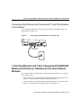
Connecting Fast Ethernet with Channelized T1 and CSU Modules
to the Network
Use a straight-through RJ-48C-to-RJ-48C cable to connect a CT1/PRI-CSU port to an
RJ-48C jack. (See Figure 5-7.)
Figure 5-7
Connecting a CT1/PRI-CSU Port to an RJ-48C Jack
FE–PRI
FDX
COLL
LINK
100Mbps
10/100BaseT
CTRLR 0
CARRIER
DETECT
REMOTE
ALARM
LOCAL
ALARM
LOOP
BACK
1FE-1CT1-CSU
EN
H7469
CT1/PRI CSU
port (RJ-48C)
RJ-48C jack
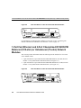
1-Port Fast Ethernet and 1-Port Channelized E1/ISDN PRI
Balanced (120-ohm) or Unbalanced (75-ohm) Network
Modules
This section provides information about the following network modules for Cisco 3600
series modular routers.
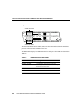
•
1-port Fast Ethernet 1-port channelized E1/ISDN PRI balanced (120-ohm) network
module—Cisco product number NM-1FE1CE1B. (See Figure 5-8.)
•
1-port Fast Ethernet 1-port channelized E1/ISDN PRI unbalanced (75-ohm) network
module—Cisco product number NM-1FE1CE1U. (See Figure 5-8.)
Connecting Fast Ethernet PRI Network Modules to a Network 5-7
1-Port Fast Ethernet and 2-Port Channelized E1/ISDN PRI Balanced (120-ohm) or Unbalanced (75-ohm)
Figure 5-8
1-Port Fast Ethernet 1-Port Channelized E1 Network Module
FE-PRI
1FE-1CE1-B/U
EN
15230
FDX
100Mbps
LINK
COLL
CARRIER
DETECT
LOOP
BACK
LOCAL
ALARM
REMOTE
ALARM
10/100BaseT
CTRLR 0
For information on connecting these modules to a network, see the “Connecting Fast
Ethernet Channelized E1 Modules to the Network” section on page 5-9.
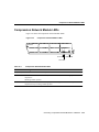
1-Port Fast Ethernet and 2-Port Channelized E1/ISDN PRI
Balanced (120-ohm) or Unbalanced (75-ohm) Network
Modules
This section provides information about the following network modules for Cisco 3600
series modular routers.
•
1-port Fast Ethernet 2-port channelized E1/ISDN PRI balanced (120-ohm) network
module—Cisco product number NM-1FE2CE1B. (See Figure 5-9.)
•
1-port Fast Ethernet 2-port channelized E1/ISDN PRI unbalanced (75-ohm) network
module—Cisco product number NM-1FE2CE1U. (See Figure 5-9.)
CARRIER
DETECT
LOOP
BACK
1FE-2CE1-B/U
LOCAL
ALARM
FE-PRI
1-Port Fast Ethernet 2-Port Channelized E1 Network Module
REMOTE
ALARM
Figure 5-9
CTRLR 1
5-8
Cisco Network Modules Hardware Installation Guide
EN
10978
FDX
100Mbps
LINK
COLL
CARRIER
DETECT
LOOP
BACK
LOCAL
ALARM
REMOTE
ALARM
10/100BaseT
CTRLR 0
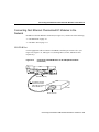
Connecting Fast Ethernet Channelized E1 Modules to the Network
Connecting Fast Ethernet Channelized E1 Modules to the
Network
In addition to the Fast Ethernet connection (see Figure 5-3), connect one of the following:
•
•
CE1/PRI-B Port on page 5-9
CE1/PRI-U Port on page 5-11
CE1/PRI-B Port
Use the appropriate cable to connect a CE1/PRI-B (120-ohm) port to an E1 CSU. (See
Figure 5-10, Figure 5-11, and Figure 5-12, showing DB-15, twinax, and RJ-45 CSUs
respectively.)
Figure 5-10
Connecting a CE1/PRI-B Port to an E1 CSU (DB-15-to-DB-15
Connectors)
FE-PRI
COLL
LINK
FDX
10/100BaseT
CTRLR 0
100Mbps
CARRIER
DETECT
EN
CE1/PRI-B (DB-15)
E1 cable for 120-ohm
balanced connections
with a DB-15 connector
at the network end
H7470
REMOTE
ALARM
LOCAL
ALARM
LOOP
BACK
1FE-1CE1-B/U
E1 CSU
DB-15 connector
Connecting Fast Ethernet PRI Network Modules to a Network 5-9
1-Port Fast Ethernet and 2-Port Channelized E1/ISDN PRI Balanced (120-ohm) or Unbalanced (75-ohm)
Figure 5-11
Connecting a CE1/PRI-B Port to an E1 CSU (DB-15-to-Twinax
Connectors)
FE-PRI
COLL
LINK
FDX
10/100BaseT
CTRLR 0
100Mbps
CARRIER
DETECT
REMOTE
ALARM
LOCAL
ALARM
LOOP
BACK
1FE-1CE1-B/U
EN
H7473
CE1/PRI port (DB-15)
E1 cable for 75-ohm
balanced connections
with twinax connectors
at the network end
E1 CSU
Twinax connectors
5-10
Cisco Network Modules Hardware Installation Guide
Connecting Fast Ethernet Channelized E1 Modules to the Network
Figure 5-12
Connecting a CE1/PRI-B Port to an E1 CSU (DB-15-to-RJ-45
Connectors)
FE-PRI
COLL
LINK
FDX
10/100BaseT
CTRLR 0
100Mbps
CARRIER
DETECT
REMOTE
ALARM
LOCAL
ALARM
LOOP
BACK
1FE-1CE1-B/U
EN
CE1/PRI port (DB-15)
H7472
E1 cable for 120-ohm
balanced connections
with an RJ-45 connector
at the network end
RJ-45 jack
CE1/PRI-U Port
Use the appropriate cable to connect a CE1/PRI-U (75-ohm) port to an E1 CSU.
Figure 5-13 shows a CSU with BNC connectors.
Connecting Fast Ethernet PRI Network Modules to a Network 5-11
Fast Ethernet PRI Module LEDs
Figure 5-13
Connecting a CE1/PRI-U Module to an E1 CSU (DB-15-to-BNC
Connectors)
FE-PRI
COLL
LINK
FDX
10/100BaseT
CTRLR 0
100Mbps
CARRIER
DETECT
REMOTE
ALARM
LOCAL
ALARM
LOOP
BACK
1FE-1CE1-B/U
EN
CE1/PRI-U
H7471
E1 cable for 75-ohm
unbalanced connections
with BNC connectors
at the network end
E1 CSU
BNC connectors
Fast Ethernet PRI Module LEDs
All network modules have an enable (EN) LED. This LED indicates that the module has
passed its self-tests and is available to the router.
All Fast Ethernet PRI modules have four LEDS for the Fast Ethernet port, and four
additional LEDs for each PRI port. Figure 5-14 shows LEDs for the 1-port Fast Ethernet
2-port channelized E1/ISDN PRI balanced (120-ohm) network module as an example.
5-12
Cisco Network Modules Hardware Installation Guide
Fast Ethernet PRI Module LEDs
Figure 5-14
Fast Ethernet and ISDN PRI LEDs
CARRIER
DETECT
LOOP
BACK
CTRLR 1
CARRIER
DETECT
LOCAL
ALARM
FE-PRI
1FE-2CE1-B/U
REMOTE
ALARM
ISDN PRI
LEDs
CTRLR 0
Fast Ethernet
LEDs
ISDN PRI
LEDs
EN
15231
FDX
100Mbps
LINK
COLL
LOOP
BACK
LOCAL
ALARM
REMOTE
ALARM
10/100BaseT
Enable
LED
Table 5-1 describes Fast Ethernet LEDs. Table 5-2 describes ISDN PRI LEDs.
Table 5-1
Fast Ethernet LEDs
LED
Color
Meaning
COLL
Yellow
Collision activity is occurring on the network.
LINK
Green
A link has been established with the station at the other end of the
cable.
100Mbps
Green
Speed of the interface is 100 Mbps.
FDX
Green
Interface is in full-duplex mode.
Connecting Fast Ethernet PRI Network Modules to a Network 5-13
Fast Ethernet PRI Module LEDs
Table 5-2
5-14
ISDN PRI LEDs
LED
Color
Meaning
REMOTE ALARM
Yellow
A remote source is indicating an error at its end of the
connection.
LOCAL ALARM
Yellow
Incoming signal shows loss of signal, loss of frame, or
excessive errors.
LOOPBACK
Yellow
Line or local loopback state is set or detected.
CARRIER
DETECT
Green
DS-1 carrier to the network is detected.
Cisco Network Modules Hardware Installation Guide
C H A PT E R
6
Connecting Serial Network
Modules to a Network
This chapter describes how to connect and configure serial network modules in Cisco
modular routers, and describes the following:
•
•
•
•
•
•
About Serial Connections on page 6-1
Connecting Asynchronous Network Modules to Asynchronous Devices on page 6-4
Asynchronous Network Modules Interface Numbering on page 6-5
4-Port Serial Network Module on page 6-10
16-Port and 32-Port Asynchronous Serial Network Module on page 6-13
4-Port and 8-Port Asynchronous/Synchronous Serial Network Module on page 6-15
About Serial Connections
Serial connections are provided by the WAN interface cards and network modules. The
serial WAN interface card can be installed in either slot of a 2-slot module. For more
information on WAN interface cards, see the publication Cisco WAN Interface Cards
Hardware Installation Guide.
Before you connect a device to a serial port, you need to know the following:
•
Type of device, data terminal equipment (DTE) or data communications equipment
(DCE), you are connecting to the synchronous serial interface
•
•
Type of connector, male or female, required to connect to the device
Signaling standard required by the device
Connecting Serial Network Modules to a Network 6-1
About Serial Connections
Serial DTE or DCE Devices
A device that communicates over a synchronous serial interface is either a DTE or DCE
device. A DCE device provides a clock signal that paces the communications between the
device and the router. A DTE device does not provide a clock signal. DTE devices usually
connect to DCE devices. The documentation that accompanied the device should indicate
whether it is a DTE or DCE device. (Some devices have a jumper to select either DTE or
DCE mode.) If you cannot find the information in the documentation, see Table 6-1 to help
you select the proper device type.
Table 6-1
Identifying the Device Type
Device Type
Gender
Typical Devices
DTE
Male1
Terminal
PC
DCE
Female
2
Modem
CSU/DSU3
Multiplexer
1
2
3
If pins protrude from the base of the connector, the
connector is male.
If the connector has holes to accept pins, the connector is
female.
CSU/DSU = channel service unit/data service unit.
Signaling Standards Supported
The synchronous serial ports available for the router support the following signaling
standards: EIA/TIA-232, EIA/TIA-449, V.35, X.21, and EIA-530. You can order a Cisco
DB-60 shielded serial transition cable that has the appropriate connector for the standard
you specify. The documentation for the device you want to connect should indicate the
standard used for that device. The router end of the shielded serial transition cable has a
DB-60 connector, which connects to the DB-60 port on a serial WAN interface card. The
other end of the serial transition cable is available with the connector appropriate for the
standard you specify.
6-2
Cisco Network Modules Hardware Installation Guide
Distance Limitations
The synchronous serial port can be configured as DTE or DCE (except EIA-530, which is
DTE only), depending on the attached cable. To order a shielded cable, contact customer
service. (See the Cisco Information Packet publication that came with your router.)
Note All serial ports configured as DTE require external clocking from a CSU/DSU or
other DCE device.
Although manufacturing your own serial cables is not recommended (because of the small
size of the pins on the DB-60 serial connector), cable pinouts are provided in the online
document Cisco Modular Access Router Cable Specifications. This document is located on
the Documentation CD-ROM that accompanied your router, and on Cisco Connection
Online.
Distance Limitations
Serial signals can travel a limited distance at any given bit rate; generally, the slower the
data rate, the greater the distance. All serial signals are subject to distance limits, beyond
which a signal degrades significantly or is completely lost.
Table 6-2 lists the recommended maximum speeds and distances for each serial interface
type; however, if you understand potential electrical problems and compensate for them,
you may get good results at speeds and distances greater than those listed. For instance, the
recommended maximum rate for V.35 is 2 Mbps, but 4 Mbps is commonly used.
Table 6-2
Serial Interace Speeds and Distances
EIA/TIA-232
Distance
EIA/TIA-449, X.21, V.35, EIA-530
Distance
Rate (bps)
Feet
Meters
Feet
Meters
2400
200
60
4100
1250
4800
100
30
2050
625
9600
50
15
1025
312
19200
25
7.6
513
156
Connecting Serial Network Modules to a Network 6-3
Connecting Asynchronous Network Modules to Asynchronous Devices
Table 6-2
Serial Interace Speeds and Distances (continued)
EIA/TIA-232
Distance
EIA/TIA-449, X.21, V.35, EIA-530
Distance
Rate (bps)
Feet
Meters
Feet
Meters
38400
12
3.7
256
78
56000
8.6
2.6
102
31
1544000 (T1)
–
–
50
15
Balanced drivers allow EIA/TIA-449 signals to travel greater distances than EIA/TIA-232
signals. The recommended distance limits for EIA/TIA-449 shown in Table 6-2 are also
valid for V.35, X.21, and EIA-530. Typically, EIA/TIA-449 and EIA-530 support 2-Mbps
rates, and V.35 can support 4-Mbps rates.
Asynchronous/Synchronous Serial Module Baud Rates
The following baud-rate limitations apply to the slow-speed serial interfaces found in the
Asynchronous/Synchronous serial modules:
•
The maximum baud rate on the slow-speed asynchronous interface is 115.2 kbps. The
traffic throughput rate allowed will be full 115.2 kbps with 10 percent of traffic in the
opposite direction.
•
The maximum baud rate for the slow-speed synchronous interface is 128 kbps full
duplex.
Connecting Asynchronous Network Modules to
Asynchronous Devices
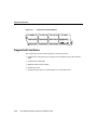
An asynchronous network module provides two or four 68-pin receptacles. Each receptacle
connects to asynchronous devices by means of an octal cable that provides a 68-pin plug at
the module end and eight connectors at the network end, one for each of the eight
EIA/TIA-232 serial ports. Depending on the type of cable, the network end consists of
either RJ-45 plugs or male DB-25 connectors. RJ-45-to-DB-25 adapters are also available.
6-4
Cisco Network Modules Hardware Installation Guide
Asynchronous Network Modules Interface Numbering
Ports are numbered from right to left and from bottom to top, as labeled on the module’s
rear panel. (See the “Asynchronous Network Modules Interface Numbering” section on
page 6-5.)
Octal cables are not provided with the network module. For ordering information, see the
“Cisco Connection Online” section on page xiv.
Use an octal cable, and adapters if necessary, to connect each of the modules’s 68-pin
receptacles to one or more asynchronous modems, terminals, or other devices. (See
Figure 6-1.)
Figure 6-1
Connecting an Asynchronous Network Module to an Asynchronous
Device
ASYNC
15
11
14
10
13
9
12
8
15
11
14
10
13
9
12
8
ASYNC 24-31
ASYNC 8-15
7
3
6
2
5
1
4
0
7
3
6
2
5
1
4
0
ASYNC 16-23
ASYNC 0-7
EN
Modem or terminal
H9999
RJ-45 to DB-25 adapter
Asynchronous Network Modules Interface Numbering
Certain Cisco IOS configuration commands identify asynchronous ports by an interface
number (or a line number, which is the same as the interface number). The interface number
of a port on a asynchronous network module is related to the slot number where the module
is installed and the unit number of the port in the module.
Connecting Serial Network Modules to a Network 6-5
Asynchronous Network Modules Interface Numbering
Cisco 3600 Series 16-Port and 32-Port Interface Numbering
Cisco 3600 series routers slot numbers begin at 0 at the bottom right of the chassis, as
viewed from the rear. For example, Cisco 3620 router slots are numbered 0 and 1, as shown
in Figure 6-2. In Cisco 3640 routers, the bottom row of slots is numbered 0 and 1 and the
top row is numbered 2 and 3, as shown in Figure 6-3.
Cisco 3620 Slot Numbers Example
H7238
Figure 6-2
2W
DO NOT INSTALL WAN INTERFACE
CARDS WITH POWER APPLIED
ACT
ETHERNET 0
ETHERNET
ETH 1 1
AUI
EN
0
ETHERNET 0
Slot 1
Figure 6-3
LNK
SERIAL
AUI
EN
ACT
ETHERNET 1
LNK
ACT
LNK
ACT
1
WO 2E W1
SERIAL
INSTALLATION
ACT
BRI
NT1
B2
SEE MANUAL BEFORE
LNK
B1
ACT
NT1
2E
W1
2W
Slot 0
Cisco 3640 Slot Numbers Example
Slot 2
Slot 3
2
BRI
NT1
WO 2E W1
DO NOT INSTALL WAN INTERFACE
CARDS WITH POWER APPLIED
2W
SERIAL
ETHERNET 0
ETHERNET 1
ACT
LNK
AUI
EN
LNK
LNK
ACT
SERIAL
ETHERNET 1
STP
ACT
1
LNK
ACT
SEE MANUAL BEFORE INSTALLATION
H6551
B2
ACT
B1
ACT
2E
W1
2W
NT1
3
AUI
EN
ETHERNET 0
INPUT 100-240VAC 50/60HZ 3.0-1.5 AMPS
Slot 1
6-6
Slot 0
Cisco Network Modules Hardware Installation Guide
Power supply
Cisco 3600 Series 16-Port and 32-Port Interface Numbering
Ports in the 16-port and 32-port asynchronous network modules correspond to the outputs
of the octal cables that connect the module to the network. These ports are numbered in the
same pattern as slot numbers, beginning at 0 at the lower right and continuing from right to
left and (in the 32-port module) from bottom to top. In the 16-port module, the right
connector provides ports 0 to 7, and the left connector provides ports 8 to 15, as labeled on
the module’s rear panel. In the 32-port module, the connectors in the bottom row provide
ports 0 to 7 and 8 to 15, and the connectors in the top row provide ports 16 to 23 and 24
to 31.
The interface number of a port is determined using the following:
interface-number = (32 x slot-number) + unit-number + 1
For example, asynchronous port 12 in slot 1 corresponds to interface number (32 x 1) +
12 + 1 = 45. This is also the line number for the port. Port 12 in slot 1 is always assigned
interface number 45, regardless of whether the module in slot 0 is a 16-port asynchronous
module, a 32-port asynchronous module, or some other type of module entirely, or even
whether there is a network module in slot 0 at all. If you move the module in slot 1 to a
different slot, however, its interface numbers change.
Table 6-3 shows the range of interface numbers available for each type of asynchronous
network module in each Cisco 3600 series router slot. (Interface 0 is automatically assigned
to the console.)
Table 6-3
Cisco 3600 Series 16-Port and 32-Port Asynchronous Network
Module Interface Numbering
Slot Number
Interface Numbers
(16-Port Module)
Interface Numbers
(32-Port Module)
0
1–16
1–32
1
33–48
33–64
65–80
65–96
3
97–112
97–128
1
Cisco 3640 router only.
21
1
Connecting Serial Network Modules to a Network 6-7
Asynchronous Network Modules Interface Numbering
Cisco 2600 Series Asynchronous Port Interface Numbering
Interface numbering for Cisco 2600 series routers differs from Cisco 3600 series interface
numbering in the following ways:
•
WAN interface card slot numbers always appear as slot 0, even if the interface card is
installed in the slot labeled W1.
•
WAN interface cards are numbered dynamically, starting with the first card installed.
For example,
— If slot W0 is empty and slot W1 contains a 1-port serial WAN interface card, the
interface number would be serial 0/0.
— If slot W0 contains a 2-port serial WAN interface card and slot W1 contains a 1-port
serial interface card, serial 0/0 and 0/1 would reside in slot W0 and serial 0/2 would
reside in slot W1.
4-Port and 8-Port Interface Numbering
Existing 4-port and 8-port asynchronous/synchronous network modules, when configured
for asynchronous operation under Cisco IOS releases prior to 11.2(7)P, use a different
interface numbering algorithm:
interface-number = (16 x slot-number) + unit-number + 1
Table 6-4 shows the numbers available under this numbering scheme. These interface
numbers create potential conflicts with the numbers assigned to 16-port and 32-port
asynchronous modules: it would be possible for a 16-port or 32-port asynchronous module
in one slot to overlap the interface numbers of a 4-port or 8-port asynchronous/synchronous
module in another slot.
Table 6-4
6-8
4-Port and 8-Port Asynchronous Network Module Interface
Numbering
Slot Number
Interface Numbers
(4-Port Module)
Interface Numbers
(8-Port Module)
0
1–4
1–8
1
17–20
17–24
Cisco Network Modules Hardware Installation Guide
4-Port and 8-Port Interface Numbering
Table 6-4
4-Port and 8-Port Asynchronous Network Module Interface
Numbering (continued)
Slot Number
Interface Numbers
(4-Port Module)
Interface Numbers
(8-Port Module)
21
33–36
33–40
1
49–52
49–56
3
1
Cisco 3640 router only.
To prevent this conflict, Cisco IOS Release 11.2(7)P, which is required to operate 16-port
and 32-port asynchronous network modules, checks when it boots for the presence of
4-port and 8-port asynchronous/synchronous network modules configured as
asynchronous. If if finds any, it rewrites the starting configuration in nonvolatile random
access memory (NVRAM), if necessary, to adopt the new line numbering scheme for these
modules, as shown in Table 6-5.
Table 6-5
New 4-Port and 8-Port Asynchronous Network Module Interface
Numbering
Slot Number
Interface Numbers
(4-Port Module)
Interface Numbers
(8-Port Module)
0
1–4
1–8
1
33–36
33–40
21
65–68
65–72
3
97–100
97–104
1
Cisco 3640 router only.
1
When an automatic configuration update is performed, the following message appears:
Line number convention changed from 16 lines/slot to 32 lines/slot.
Connecting Serial Network Modules to a Network 6-9
4-Port Serial Network Module
4-Port Serial Network Module
This section provides information about the 4-port serial network module (Cisco product
number NM-4T) for Cisco modular routers. With the appropriate serial transition cable,
each port on this module can provide a EIA/TIA-232, EIA/TIA-449, V.35, X.21,
DTE/DCE, EIA-530 DTE, or nonreturn to zero/nonreturn to zero inverted (NRZ/NRZI)
serial interface, in any combination. The module provides a synchronous data rate of 8
MB/sec on port 0, 4 MB/sec each on port 0 and port 2, or 2 MB on all four ports
simultaneously. (See Figure 6-4.)
Figure 6-4
4-Port Serial Network Module
Serial ports (DB-60)
SERIAL
4T
SERIAL 2
SERIAL 1
SERIAL 0
EN
CN/LP RXC
RXD
TXC
TXD
CN/LP RXC
RXD
TXC
TXD
CN/LP RXC
RXD
TXC
TXD
CN/LP RXC
RXD
TXC
TXD
H9597
SERIAL 3
Connecting the 4-Port Serial Module to a Network
The 4-port serial network module provides four universal high-density 60-pin receptacles.
The serial cable attached to each receptacle determines the port’s electrical interface type
and mode, data terminal equipment (DTE) or data communications equipment (DCE).
Types of Serial Cables
Cisco Systems offers five types of serial cables (also called serial adapter cables or
transition cables):
•
•
6-10
EIA/TIA-232 Serial Cable Assembly
EIA/TIA-449 Serial Cable Assembly
Cisco Network Modules Hardware Installation Guide
Connecting the 4-Port Serial Module to a Network
•
•
•
V.35 Serial Cable Assembly
X.21 Serial Cable Assembly
EIA-530 Serial Cable Assembly
All serial cables provide a universal plug at the network module end. The network end of
each cable provides the physical connectors most commonly used for the interface. For
example, the network end of the EIA/TIA-232 serial cable is a DB-25 connector, the most
widely used EIA/TIA-232 connector.
All serial interface types except EIA-530 are available in DTE or DCE format: DTE with a
plug connector at the network end and DCE with a receptacle at the network end. V.35 is
available in either mode with either gender at the network end. EIA-530 is available in DTE
only.
Serial cables are not provided with the network module. For ordering information, see the
“Cisco Connection Online” section on page xiv.
Connecting the Module to the Network
After you install a 4-port serial module, use the appropriate serial cable to connect each of
the module’s DB-60 serial ports to a synchronous modem, channel service unit/data service
unit (CSU/DSU), or other DCE equipment. (See Figure 6-5.)
Connecting Serial Network Modules to a Network 6-11
4-Port Serial Network Module
Figure 6-5
Connecting a 4-Port Serial Module to a CSU/DSU
SERIAL
4T
CN/LP RXC RXD
TXC
TXD
SERIAL 2
CN/LP RXC RXD
SERIAL 1
SERIAL 0
EN
TXC
TXD
CN/LP RXC RXD
TXC
TXD
CN/LP RXC RXD
TXC
TXD
H9598
SERIAL 3
Serial port (DB-60)
Serial transition
cable
CSU/DSU or
other DCE
EIA/TIA-232, EIA/TIA-449, V.35,
X.21, or EIA-530 connector
4-Port Serial Network Module LEDs
All network modules have an enable (EN) LED. This LED indicates that the module has
passed its self-tests and is available to the router.
Each port on the 4-port serial network module also has the additional LEDs shown in
Figure 6-6 and described in Table 6-6.
6-12
Cisco Network Modules Hardware Installation Guide
16-Port and 32-Port Asynchronous Serial Network Module
Figure 6-6
4-Port Serial Network Module LEDs
SERIAL
4T
SERIAL 2
SERIAL 1
SERIAL 0
EN
CN/LP RXC
RXD
TXC
TXD
CN/LP RXC
RXD
TXC
TXD
CN/LP RXC
RXD
TXC
TXD
Serial port LEDs
Table 6-6
CN/LP RXC
RXD
TXC
TXD
H9599
SERIAL 3
Enable LED
4-Port Serial Network Module LEDs
LED
Meaning
CN/LP
Connect when green, loopback when yellow
RXC
Receive clock
RXD
Receive activity
TXC
Transmit clock
TXD
Transmit activity
16-Port and 32-Port Asynchronous Serial Network Module
This section provides information about the following network modules for Cisco modular
routers:
•
16-port asynchronous network module—(Cisco product number NM-16A). (See
Figure 6-7.)
•
32-port asynchronous network module—(Cisco product number NM-32A). (See
Figure 6-8.)
When used with corresponding octal cables, these modules provide 16 or 32 EIA/TIA-232
data terminal equipment (DTE) serial interfaces. Speeds up to 134.4 kbps are supported.
Connecting Serial Network Modules to a Network 6-13
16-Port and 32-Port Asynchronous Serial Network Module
Figure 6-7
16-Port Asynchronous Network Module
ASYNC
11
7
3
14
10
6
2
13
9
5
1
12
8
4
0
ASYNC 0-7
EN
H9996
ASYNC 8-15
15
68-pin connectors
Figure 6-8
32-Port Asynchronous Network Module
ASYNC
27
23
19
30
26
22
18
29
25
21
17
28
24
20
16
15
11
7
3
14
10
6
2
13
9
5
1
12
8
4
0
ASYNC 8-15
ASYNC 16-23
ASYNC 0-7
EN
H9997
ASYNC 24-31
31
68-pin connectors
Asynchronous Network Module LEDs
All network modules have an enable (EN) LED. This LED indicates that the module has
passed its self-tests and is available to the router.
Each port on an asynchronous network module also has a green status LED to indicate that
the port is connected to the network. These LEDs are grouped in blocks of eight to the left
of each module, and labeled with the port numbers. (See Figure 6-9 and Figure 6-10.)
6-14
Cisco Network Modules Hardware Installation Guide
4-Port and 8-Port Asynchronous/Synchronous Serial Network Module
Figure 6-9
16-Port Asynchronous Network Module LEDs
ASYNC
11
7
3
14
10
6
2
13
9
5
1
12
8
4
0
Status LEDs
Figure 6-10
ASYNC 0-7
EN
H9994
ASYNC 8-15
15
Status LEDs
Enable LED
32-Port Asynchronous Network Module LEDs
Status LEDs
Status LEDs
ASYNC
27
23
19
30
26
22
18
29
25
21
17
28
24
20
16
15
11
7
3
14
10
6
2
13
9
5
1
12
8
4
0
Status LEDs
ASYNC 8-15
Status LEDs
ASYNC 16-23
ASYNC 0-7
EN
H9995
ASYNC 24-31
31
Enable LED
4-Port and 8-Port Asynchronous/Synchronous Serial
Network Module
This section provides information about the following network modules for Cisco modular
routers:
Connecting Serial Network Modules to a Network 6-15
4-Port and 8-Port Asynchronous/Synchronous Serial Network Module
•
4-port asynchronous/synchronous serial network module—(Cisco product number
NM-4A/S). (See Figure 6-11.)
•
8-port asynchronous/synchronous serial network module—(Cisco product number
NM-8A/S). (See Figure 6-12.)
With the appropriate serial transition cable, the ports on these modules can provide an
EIA/TIA-232, EIA/TIA-449, V.35, X.21, DTE/DCE, EIA-530 DTE, or NRZ/NRZI serial
interface.
Figure 6-11
4-Port Asynchronous/Synchronous Serial Network Module
Asynchronous/synchronous serial ports (DB-60)
CN/LP RXC
RXD
TXC
TXD
CN/LP RXC
RXD
TXC
TXD
2
3
Figure 6-12
CN/LP RXC
RXD
TXC
TXD
1
CN/LP RXC
RXD
TXC
TXD
0
EN
H7255
SERIAL
A/S
8-Port Asynchronous/Synchronous Serial Network Module
Asynchronous/synchronous serial ports (DB-60)
SERIAL
A/S
RXD
TXC
TXD
CN/LP RXC
3
6-16
CN/LP RXC
RXD
TXC
TXD
6
RXD
TXC
TXD
CN/LP RXC
RXD
TXC
TXD
5
CN/LP RXC
RXD
TXC
TXD
2
Cisco Network Modules Hardware Installation Guide
CN/LP RXC
1
CN/LP RXC
RXD
TXC
TXD
CN/LP RXC
RXD
TXC
TXD
4
RXD
TXC
TXD
0
EN
H7256
CN/LP RXC
7
Asynchronous/Synchronous Serial Module LEDs
Asynchronous/Synchronous Serial Module LEDs
Figure 6-13 shows LEDs for the 4-port asynchronous/synchronous serial network module.
Figure 6-14 shows LEDs for the 8-port asynchronous/synchronous serial network module.
Figure 6-13
4-Port Asynchronous/Synchronous Serial Network Module LEDs
CN/LP RXC
RXD
TXC
TXD
CN/LP RXC
RXD
TXC
TXD
2
3
CN/LP RXC
RXD
TXC
TXD
1
CN/LP RXC
RXD
TXC
EN
Enable LED
Asynchronous/synchronous serial port LEDs
Figure 6-14
TXD
0
H7268
SERIAL
A/S
8-Port Asynchronous/Synchronous Serial Network Module LEDs
Asynchronous/synchronous serial port LEDs
SERIAL
A/S
RXD
TXC
TXD
CN/LP RXC
3
CN/LP RXC
RXD
TXC
TXD
6
RXD
TXC
CN/LP RXC
RXD
TXC
TXD
5
TXD
CN/LP RXC
2
RXD
TXC
TXD
CN/LP RXC
RXD
TXC
TXD
CN/LP RXC
RXD
TXC
TXD
4
CN/LP RXC
RXD
TXC
TXD
1
Asynchronous/synchronous serial port LEDs
0
EN
H7269
CN/LP RXC
7
Enable LED
All network modules have an enable (EN) LED. This LED indicates that the module has
passed its self-tests and is available to the router.
Connecting Serial Network Modules to a Network 6-17
4-Port and 8-Port Asynchronous/Synchronous Serial Network Module
Each port on an asynchronous/synchronous serial network module also has the additional
LEDs shown in Table 6-7.
Table 6-7
6-18
Asynchronous/Synchronous Serial Network Module LEDs
LED
Meaning
CN/LP
Connect when green, loopback when yellow
RXC
Receive clock
RXD
Receive activity
TXC
Transmit clock
TXD
Transmit activity
Cisco Network Modules Hardware Installation Guide
C H A PT E R
7
Connecting ISDN BRI Network
Modules to a Network
This chapter describes how to connect Integrated Services Digital Network (ISDN) Basic
Rate Interface (BRI) network modules in Cisco modular routers, and describes the
following:
•
•
•
Upgrading ISDN BRI Network Modules on page 7-1
4-Port and 8-Port ISDN BRI S/T Network Modules on page 7-3
4-Port and 8-Port ISDN BRI U Network Modules on page 7-6
Unless specifically identified, references to BRI modules in this chapter include all ISDN
BRI network modules.
Note Do not install an ISDN BRI network module in the same chassis as an ISDN Primary
Rate Interface (PRI) network module, unless you are using Cisco IOS Release 11.3(3)T or
later. Earlier Cisco IOS releases do not support this configuration.
Upgrading ISDN BRI Network Modules
If your Cisco 3600 series router contains an ISDN BRI network module (product numbers:
NM-4B-S/T, NM-4B-U, NM-8B-S/T, NM-8B-U) and a digital modem network module
(product numbers: NM-6DM, NM-12DM, NM-18DM, NM-24DM, NM-30DM), your
ISDN BRI network module has to be upgraded to the minimum version shown in Table 7-1.
Earlier versions of the ISDN BRI network module cannot send modem calls to the digital
modem network module.
Connecting ISDN BRI Network Modules to a Network 7-1
Upgrading ISDN BRI Network Modules
Table 7-1
ISDN BRI Network Module Upgrade Versions
Module
Minimum Version
NM-4B-S/T
800-01236-03
NM-4B-U
800-01238-06
NM-8B-S/T
800-01237-03
NM-8B-U
800-01239-06
If the BRI module is the wrong revision, you see a message similar to this one when the
router boots:
The BRI network module in slot 0 is incompatible with the digital modems
installed in the router.
To determine the revision level, you can examine the network module itself (outside the
router), or use the Cisco IOS show diag command. The label on the module board should
show a part number beginning with 800- and ending with -03 or -06. A BRI S/T module
whose part number ends with -01 or -02 needs to be upgraded, as does a BRI U module
whose part number is lower than -06.
The output of the show diag command looks similar to the following:
Port adapter is analyzed
Port adapter insertion time unknown
Hardware revision 1.0
Board revision
Serial number
4152626
Part number
Test history
0x0
RMA number
EEPROM format version 1
EEPROM contents (hex):
0x20: 01 26 01 00 00 3F 5D 32 50 04 CC 01 00
0x30: 50 00 00 00 96 11 04 17 FF FF FF FF FF
A0
800-01236-01
00-00-00
00 00 00
FF FF FF
To order network module upgrades, see the “Cisco Connection Online” section on page xiv.
7-2
Cisco Network Modules Hardware Installation Guide
4-Port and 8-Port ISDN BRI S/T Network Modules
4-Port and 8-Port ISDN BRI S/T Network Modules
This section provides information about the following network modules for Cisco modular
routers:
•
4-port ISDN BRI network module—(Cisco product number NM-4B-S/T or
CPANM-4B-S/T). Connects to an ISDN WAN through an external Network
Termination 1 (NT1) device (also known as an S/T interface). (See Figure 7-1.) This
module is also referred to as the 4-port BRI S/T network module.
•
8-port ISDN BRI network module—(Cisco product number NM-8B-S/T or
CPANM-8B-S/T). Connects to an ISDN WAN through an external NT1 device (also
known as an S/T interface). (See Figure 7-2.) This module is also referred to as the
8-port BRI S/T network module.
Figure 7-1
4-Port ISDN BRI Network Module (S/T Interface)
BRI
S/T
BRI 2
BRI 1
BRI 0
EN
B1
B2
B1
B2
B1
B2
B1
B2
H7267
BRI 3
Enable LED
BRI S/T LEDs
Figure 7-2
8-Port ISDN BRI Network Module (S/T Interface)
BRI S/T ports (RJ-45)
BRI S/T ports (RJ-45)
BRI
S/T
BRI 6
BRI 5
BRI 4
BRI 3
BRI 2
BRI 1
BRI 0
EN
B1
B2
B1
B2
B1
B2
B1
B2
B1
B2
B1
B2
B1
B2
B1
B2
H7254
BRI 7
Connecting ISDN BRI Network Modules to a Network 7-3
4-Port and 8-Port ISDN BRI S/T Network Modules
Connecting BRI S/T Modules to a Network
To connect a BRI S/T network module to a network, use a straight-through RJ-45-to-RJ-45
cable to connect the ISDN BRI port to an NT1. (See Figure 7-3.)
Figure 7-3
Connecting an ISDN BRI S/T Network Module to an NT1
BRI
ST
B1
B2
BRI 6
B1
BRI 5
BRI 4
BRI 3
BRI 2
BRI 1
BRI 0
EN
B2
B1
B2
B1
B2
B1
B2
B1
B2
B1
B2
B1
B2
H7475
BRI 7
BRI S/T port (RJ-45)
NT1 device
S/T port
BRI S/T Module LEDs
Figure 7-4 shows LEDs for the 4-port BRI S/T network module, and Figure 7-5 shows
LEDs for the 8-port BRI S/T network module.
7-4
Cisco Network Modules Hardware Installation Guide
BRI S/T Module LEDs
Figure 7-4
4-Port ISDN BRI S/T Network Module LEDs
BRI
S/T
BRI 2
BRI 1
BRI 0
EN
B1
B2
B1
B2
B1
B2
B1
B2
H7267
BRI 3
Enable LED
BRI S/T LEDs
Figure 7-5
8-Port ISDN BRI S/T Network Module LEDs
BRI
S/T
BRI 6
BRI 5
BRI 4
BRI 3
BRI 2
BRI 1
BRI 0
EN
B1
B2
B1
B2
B1
B2
B1
B2
B1
B2
B1
B2
B1
B2
B1
B2
H7266
BRI 7
Enable LED
BRI S/T LEDs
BRI S/T LEDs
All network modules have an enable (EN) LED. This LED indicates that the module has
passed its self-tests and is available to the router.
In addition, BRI S/T modules have two LEDs for each port. These LEDs indicate call
activity on the two ISDN BRI B channels, as listed in Table 7-2.
Table 7-2
BRI S/T Network Module LEDs
LED
Meaning
B1
Call active on B1 channel
B2
Call active on B2 channel
Connecting ISDN BRI Network Modules to a Network 7-5
4-Port and 8-Port ISDN BRI U Network Modules
4-Port and 8-Port ISDN BRI U Network Modules
This section provides information about the following network modules for Cisco modular
routers:
•
4-port ISDN BRI with NT1 network module—(Cisco product number NM-4B-U or
CPANM-4B-U). Connects to an ISDN WAN using a built-in NT1 device (also known
as a U interface). (See Figure 7-6.) This module is also referred to as the 4-port BRI U
network module.
•
8-port ISDN BRI with NT1 network module—(Cisco product number NM-8B-U or
CPANM-8B-U). Connects to an ISDN WAN using a built-in NT1 device (also known
as a U interface). (See Figure 7-7.) This module is also referred to as the 8-port BRI U
network module.
Figure 7-6
4-Port ISDN BRI with NT1 Network Module (U Interface)
BRI U ports (RJ-45)
7-6
BRI 1
B2
Cisco Network Modules Hardware Installation Guide
B1
B2
BRI 0
B1
B2
NT1
B1
EN
H7259
B2
BRI 2
NT1
B1
NT1
BRI 3
NT1
BRI
U
4-Port and 8-Port ISDN BRI U Network Modules
Figure 7-7
8-Port ISDN BRI with NT1 Network Module (U Interface)
B1
BRI 4
B1
B2
B2
BRI 3
BRI 2
BRI 1
BRI 0
B1
B2
B1
B2
B1
B2
NT1
B2
NT1
B2
B1
B2
EN
H7264
BRI 5
NT1
B1
NT1
BRI 6
NT1
B1
NT1
BRI 7
NT1
BRI
U
NT1
NT1 LEDs
Enable LED
ISDN BRI LEDs
Connecting ISDN BRI Network Modules to a Network 7-7
4-Port and 8-Port ISDN BRI U Network Modules
Connecting BRI U Modules to a Network
To connect a BRI U module to a network, use a straight-through RJ-45-to-RJ-45 cable to
connect the ISDN BRI port to an RJ-45 jack. (See Figure 7-8.)
Figure 7-8
Connecting a BRI U Network Module to an RJ-45 ISDN Jack
BRI U port (RJ-45)
B1
B2
BRI 1
B1
B2
BRI 0
B1
B2
EN
H7474
BRI 2
NT1
B2
NT1
B1
NT1
BRI 3
NT1
BRI
U
Straight-through
RJ-45-to-RJ-45
cable
RJ-45 jack
BRI U Modules LEDs
Figure 7-9 shows LEDs for the 4-port BRI U network module, and Figure 7-10 shows
LEDs for the 8-port BRI U network module.
7-8
Cisco Network Modules Hardware Installation Guide
BRI U Modules LEDs
Figure 7-9
4-Port ISDN BRI U Network Module LEDs
NT1 LEDs
B2
BRI 1
B1
B2
BRI 0
B1
NT1
B1
B2
EN
H7265
B2
BRI 2
NT1
B1
NT1
BRI 3
NT1
BRI
U
Enable LED
ISDN BRI LEDs
Figure 7-10
8-Port ISDN BRI U Network Module LEDs
B1
BRI 4
B1
B2
B2
BRI 3
BRI 2
BRI 1
BRI 0
B1
B2
B1
B2
B1
B2
NT1
B2
NT1
B2
B1
B2
EN
H7264
BRI 5
NT1
B1
NT1
BRI 6
NT1
B1
NT1
BRI 7
NT1
BRI
U
NT1
NT1 LEDs
Enable LED
ISDN BRI LEDs
All network modules have an enable (EN) LED. This LED indicates that the module has
passed its self-tests and is available to the router.
Connecting ISDN BRI Network Modules to a Network 7-9
4-Port and 8-Port ISDN BRI U Network Modules
In addition, BRI U modules have three LEDs for each port. Two of these LEDs indicate call
activity on the two ISDN BRI B channels, as listed in Table 7-3. The third LED, labeled
NT1, indicates synchronization status of the NT1.
Table 7-3
7-10
BRI U Network Modules LEDs
LED
Meaning
B1
Activity on B1 channel
B2
Activity on B2 channel
NT1
Synchronous status of NT1
Cisco Network Modules Hardware Installation Guide
C H A PT E R
8
Connecting ISDN PRI Network
Modules to a Network
This chapter describes how to connect Integrated Services Digital Network (ISDN)
Primary Rate Interface (PRI) network modules used in Cisco modular routers, and
describes the following modules:
•
•
•
1-Port and 2-Port Channelized T1/ISDN PRI Network Modules on page 8-2
•
1-Port and 2-Port Channelized E1/ISDN PRI Unbalanced (75-ohm) Network Modules
on page 8-14
1-Port and 2-Port Channelized T1/ISDN PRI with CSU Network Modules on page 8-5
1-Port and 2-Port Channelized E1/ISDN PRI Balanced (120-ohm) Network Modules on
page 8-9
Unless specifically identified, references to PRI modules in this chapter include all these
network modules.
Note Do not install an ISDN Basic Rate Interface (BRI) network module in the same
chassis as an ISDN PRI network module, unless you are using Cisco IOS Release 11.3(3)T
or later. Earlier Cisco IOS releases do not support this configuration.
CT1/PRI modules are available with or without a built-in channel service unit (CSU) and
with one or two ports. The CT1/PRI modules connect to an external CSU, whereas the
CT1/PRI-CSU modules connect directly to the network. Each T1 module provides up to 24
virtual channels per T1 port, and each virtual channel is presented to the system as a serial
interface that can be configured individually. The T1 interface is the physical medium that
supports ISDN PRI.
Connecting ISDN PRI Network Modules to a Network 8-1
1-Port and 2-Port Channelized T1/ISDN PRI Network Modules
The CT1/PRI and CT1/PRI-CSU modules receive and transmit data bidirectionally at the
T1 rate of 1.544 Mbps.
1-Port and 2-Port Channelized T1/ISDN PRI Network
Modules
This section provides information about the following network modules for Cisco modular
routers:
•
1-port channelized T1/ISDN PRI network module—(Cisco product number NM-1CT1
or CPANM-1CT1). (See Figure 8-1.) This module is also referred to as the 1-port
CT1/PRI network module.
•
2-port channelized T1/ISDN PRI network module—(Cisco product number NM-2CT1
or CPANM-2CT1). (See Figure 8-2.) This module is also referred to as the 2-port
CT1/PRI network module.
Figure 8-1
1-Port Channelized T1/ISDN PRI Network Module
EN
CTRLR 0
CT1/PRI-U port (DB-15)
8-2
Cisco Network Modules Hardware Installation Guide
H7460
CARRIER
DETECT
LOOPBACK
LOCAL
ALARM
REMOTE
ALARM
cT1
PRI
Connecting CT1/PRI Modules to the Network
CARRIER
DETECT
LOOPBACK
REMOTE
ALARM
cT1
PRI
2-Port Channelized T1/ISDN PRI Network Module
LOCAL
ALARM
Figure 8-2
EN
EN
CTRLR 0
H7461
CARRIER
DETECT
LOOPBACK
LOCAL
ALARM
REMOTE
ALARM
CTRLR 1
CT1/PRI-U ports (DB-15)
Connecting CT1/PRI Modules to the Network
To connect a CT1/PRI module to the network, use a DB-15-to-DB-15 T1 serial cable to
connect the CT1/PRI port to a T1 channel service unit (CSU). (See Figure 8-3.)
Figure 8-3
Connecting a CT1/PRI Module to a T1 CSU
FE–PRI
COLL
LINK
FDX
10/100BaseT
CTRLR 0
100Mbps
CARRIER
DETECT
EN
CT1/PRI port (DB-15)
H7468
REMOTE
ALARM
LOCAL
ALARM
LOOP
BACK
1FE-1CT1
T1 serial
cable
T1 CSU
CT1/PRI port (DB-15)
Connecting ISDN PRI Network Modules to a Network 8-3
1-Port and 2-Port Channelized T1/ISDN PRI Network Modules
CT1/PRI Module LEDs
Figure 8-4 and Figure 8-5 show CT1/PRI network module LEDs.
Figure 8-4
1-Port CT1/PRI Network Module LEDs
EN
CTRLR 0
Enable LED
CT1/PRI LEDs
Figure 8-5
H7462
CARRIER
DETECT
LOOPBACK
LOCAL
ALARM
REMOTE
ALARM
cT1
PRI
2-Port CT1/PRI Network Module LEDs
CARRIER
DETECT
LOOPBACK
LOCAL
ALARM
cT1
PRI
REMOTE
ALARM
CT1/PRI LEDs
EN
CTRLR 0
CT1/PRI LEDs
H7463
CARRIER
DETECT
LOOPBACK
LOCAL
ALARM
REMOTE
ALARM
CTRLR 1
Enable LED
All network modules have an enable (EN) LED. This LED indicates that the module has
passed its self-tests and is available to the router.
All PRI modules display four additional LEDs for each port. These LEDs are described in
Table 8-1.
8-4
Cisco Network Modules Hardware Installation Guide
1-Port and 2-Port Channelized T1/ISDN PRI with CSU Network Modules
Table 8-1
ISDN PRI Network Module LEDs
LED
Meaning
REMOTE ALARM
Local alarm at remote end of connection
LOCAL ALARM
Loss of signal, loss of frame, or unavailability
because of excessive errors
LOOPBACK
Controller local loopback
CARRIER DETECT
Carrier received on telco link
1-Port and 2-Port Channelized T1/ISDN PRI with CSU
Network Modules
This section provides information about the following network modules for Cisco modular
routers:
•
1-port channelized T1/ISDN PRI with CSU network module—(Cisco product number
NM-1CT1-CSU or CPANM-1CT1-CSU). (See Figure 8-6.) This module is also
referred to as the 1-port CT1/PRI CSU network module.
•
2-port channelized T1/ISDN PRI with CSU network module—(Cisco product number
NM-2CT1-CSU or CPANM-2CT1-CSU). (See Figure 8-7.) This module is also
referred to as the 2-port CT1/PRI CSU network module.
Connecting ISDN PRI Network Modules to a Network 8-5
1-Port and 2-Port Channelized T1/ISDN PRI with CSU Network Modules
Figure 8-6
1-Port Channelized T1/ISDN PRI with CSU Network Module
cT1
CSU
RX
MON
EN
CTRLR 0
Monitor and
test ports
(Bantam)
CT1/PRI CSU
port (RJ-48)
CARRIER
DETECT
LOOPBACK
2-Port Channelized T1/ISDN PRI with CSU Network Module
LOCAL
ALARM
cT1
CSU
REMOTE
ALARM
Figure 8-7
H7465
TX
IN
CARRIER
DETECT
LOOPBACK
LOCAL
ALARM
REMOTE
ALARM
RX
OUT
CTRLR 1
RX
MON
EN
CTRLR 0
Monitor and
test ports
(Bantam)
H7464
TX
IN
CARRIER
DETECT
LOOPBACK
LOCAL
ALARM
REMOTE
ALARM
RX
OUT
CT1/PRI CSU
port (RJ-48)
Connecting CT1/PRI CSU Modules to the Network
To connect a CT1/PRI CSU module to the network, use a straight-through
RJ-48C-to-RJ-48C cable to connect the RJ-48C port to an RJ-48C jack. (See Figure 8-8.)
8-6
Cisco Network Modules Hardware Installation Guide
CT1/PRI CSU Module LEDs
Figure 8-8
Connecting a CT1/PRI CSU Module to an RJ-48C Jack
FE–PRI
FDX
COLL
LINK
CTRLR 0
100Mbps
10/100BaseT
CARRIER
DETECT
REMOTE
ALARM
LOCAL
ALARM
LOOP
BACK
1FE-1CT1-CSU
EN
H7469
CT1/PRI CSU
port (RJ-48C)
RJ-48C jack
CT1/PRI CSU Module LEDs
Figure 8-9 and Figure 8-10 show CT1/PRI CSU module LEDs.
Figure 8-9
1-Port CT1/PRI CSU Network Module LEDs
cT1
CSU
RX
MON
EN
CTRLR 0
H7467
TX
IN
CARRIER
DETECT
LOOPBACK
LOCAL
ALARM
REMOTE
ALARM
RX
OUT
CT1/PRI CSU LEDs
Connecting ISDN PRI Network Modules to a Network 8-7
1-Port and 2-Port Channelized T1/ISDN PRI with CSU Network Modules
Figure 8-10
2-Port CT1/PRI CSU Network Module LEDs
CARRIER
DETECT
LOOPBACK
LOCAL
ALARM
cT1
CSU
REMOTE
ALARM
CT1/PRI CSU LEDs
CTRLR 1
RX
MON
EN
CTRLR 0
H7466
TX
IN
CARRIER
DETECT
LOOPBACK
LOCAL
ALARM
REMOTE
ALARM
RX
OUT
CT1/PRI CSU LEDs
All network modules have an enable (EN) LED. This LED indicates that the module has
passed its self-tests and is available to the router.
All PRI modules display four additional LEDs for each port. These LEDs are described in
Table 8-2.
Table 8-2
8-8
ISDN PRI Network Module LEDs
LED
Meaning
REMOTE ALARM
Local alarm at remote end of connection
LOCAL ALARM
Loss of signal, loss of frame, or unavailability
because of excessive errors
LOOPBACK
Controller local loopback
CARRIER DETECT
Carrier received on telco link
Cisco Network Modules Hardware Installation Guide
1-Port and 2-Port Channelized E1/ISDN PRI Balanced (120-ohm) Network Modules
1-Port and 2-Port Channelized E1/ISDN PRI Balanced
(120-ohm) Network Modules
This section provides information about the following network modules for Cisco modular
routers:
•
1-port channelized E1/ISDN PRI balanced (120-ohm) network module—(Cisco
product number NM-1CE1B or CPANM-1CE1B). (See Figure 8-11.) This module is
also referred to as the 1-port CE1/PRI-B network module.
•
2-port channelized E1/ISDN PRI balanced (120-ohm) network module—(Cisco
product number NM-2CE1B or CPANM-2CE1B). (See Figure 8-12.) This module is
also referred to as the 2-port CE1/PRI-B network module.
Figure 8-11
1-Port Channelized E1/ISDN PRI Network Module (Balanced)
EN
CTRLR 0
H7260
CARRIER
DETECT
LOOPBACK
LOCAL
ALARM
REMOTE
ALARM
cE1-B
PRI
CE1/PRI-B port
CARRIER
DETECT
LOOPBACK
LOCAL
ALARM
2-Port Channelized E1/ISDN PRI Network Module (Balanced)
EN
CTRLR 0
H7261
CARRIER
DETECT
LOOPBACK
LOCAL
ALARM
CTRLR 1
REMOTE
ALARM
cE1-B
PRI
REMOTE
ALARM
Figure 8-12
CE1/PRI-B ports
Connecting ISDN PRI Network Modules to a Network 8-9
1-Port and 2-Port Channelized E1/ISDN PRI Balanced (120-ohm) Network Modules
The CE1/PRI modules are available with one or two E1 ports and with balanced or
unbalanced interfaces. CE1/PRI modules receive and transmit data bidirectionally at the E1
rate of 2.048 Mbps and provide up to 30 virtual channels per E1 port. Each of the virtual
channels is presented to the system as a serial interface that can be configured individually.
The E1 interface is the physical media that supports ISDN PRI.
CE1/PRI Module Jumper Settings
Jumpers on the CE1/PRI modules can be used to connect or disconnect receive shield to
ground. (See Table 8-3.) The default setting for balanced, 120-ohm CE1/PRI-B modules
disconnects receive shield to ground. The default setting for unbalanced, 75-ohm
CE1/PRI-U modules connects receive shield to ground. If you are experiencing ground
loop problems with E1 cabling, you may want to try changing the jumper settings in the
module.
Table 8-3
CE1/PRI Module Jumpers
CE1/PRI Module Type
Default Jumper Setting
Function
Balanced, 120 ohm
2 and 3
Disconnects receive shield from
ground
Unbalanced, 75 ohm
1 and 2
Connects receive shield to ground
Connecting CE1/PRI-B Modules to the Network
To connect a CE1/PRI-B (120-ohm) module to the network, use the appropriate cable to
connect the CE1/PRI-B port to an E1 CSU. (See Figure 8-13, Figure 8-14, and Figure 8-15,
showing DB-15, twinax, and RJ-45 CSUs respectively.)
8-10
Cisco Network Modules Hardware Installation Guide
Connecting CE1/PRI-B Modules to the Network
Figure 8-13
Connecting a 120-ohm CE1/PRI-B Module to an E1 CSU
(DB-15-to-DB-15 Connectors)
FE-PRI
COLL
LINK
FDX
10/100BaseT
CTRLR 0
100Mbps
CARRIER
DETECT
EN
CE1/PRI-B (DB-15)
E1 cable for 120-ohm
balanced connections
with a DB-15 connector
at the network end
H7470
REMOTE
ALARM
LOCAL
ALARM
LOOP
BACK
1FE-1CE1-B/U
E1 CSU
DB-15 connector
Connecting ISDN PRI Network Modules to a Network 8-11
1-Port and 2-Port Channelized E1/ISDN PRI Balanced (120-ohm) Network Modules
Figure 8-14
Connecting a 120-ohm CE1/PRI-B Module to an E1 CSU
(DB-15-to-Twinax Connectors)
FE-PRI
COLL
LINK
FDX
10/100BaseT
CTRLR 0
100Mbps
CARRIER
DETECT
REMOTE
ALARM
LOCAL
ALARM
LOOP
BACK
1FE-1CE1-B/U
EN
H7473
CE1/PRI port (DB-15)
E1 cable for 75-ohm
balanced connections
with twinax connectors
at the network end
E1 CSU
Twinax connectors
Figure 8-15
Connecting a 120-ohm CE1/PRI-B Module to an E1 CSU
(DB-15-to-RJ-45 Connectors)
FE-PRI
COLL
LINK
FDX
10/100BaseT
CTRLR 0
100Mbps
CARRIER
DETECT
REMOTE
ALARM
LOCAL
ALARM
LOOP
BACK
1FE-1CE1-B/U
EN
CE1/PRI port (DB-15)
H7472
E1 cable for 120-ohm
balanced connections
with an RJ-45 connector
at the network end
RJ-45 jack
8-12
Cisco Network Modules Hardware Installation Guide
CE1/PRI Module LEDs
CE1/PRI Module LEDs
Figure 8-16 and Figure 8-17 show CE1/PRI module LEDs.
Figure 8-16
1-Port CE1/PRI Network Module LEDs
EN
CTRLR 0
Enable LED
CE1/PRI LEDs
Figure 8-17
H7262
CARRIER
DETECT
LOOPBACK
LOCAL
ALARM
REMOTE
ALARM
cE1
PRI
2-Port CE1/PRI Network Module LEDs
CARRIER
DETECT
LOOPBACK
LOCAL
ALARM
cE1
PRI
REMOTE
ALARM
CE1/PRI LEDs
EN
CTRLR 0
CE1/PRI LEDs
H7263
CARRIER
DETECT
LOOPBACK
LOCAL
ALARM
REMOTE
ALARM
CTRLR 1
Enable LED
All network modules have an enable (EN) LED. This LED indicates that the module has
passed its self-tests and is available to the router.
All PRI modules display four additional LEDs for each port. These LEDs are described in
Table 8-4.
Connecting ISDN PRI Network Modules to a Network 8-13
1-Port and 2-Port Channelized E1/ISDN PRI Unbalanced (75-ohm) Network Modules
Table 8-4
ISDN PRI Network Module LEDs
LED
Meaning
REMOTE ALARM
Local alarm at remote end of connection
LOCAL ALARM
Loss of signal, loss of frame, or unavailability
because of excessive errors
LOOPBACK
Controller local loopback
CARRIER DETECT
Carrier received on telco link
1-Port and 2-Port Channelized E1/ISDN PRI Unbalanced
(75-ohm) Network Modules
This section provides information about the following network modules for Cisco modular
routers:
•
1-port channelized E1/ISDN PRI unbalanced (75-ohm) network module—(Cisco
product number NM-1CE1U or CPANM-1CE1U). (See Figure 8-18.) This module is
also referred to as the 1-port CE1/PRI-U network module.
•
2-port channelized E1/ISDN PRI unbalanced (75-ohm) network module—(Cisco
product number NM-2CE1U or CPANM-2CE1U). (See Figure 8-19.) This module is
also referred to as the 2-port CE1/PRI-U network module.
Figure 8-18
1-Port Channelized E1/ISDN PRI Network Module (Unbalanced)
EN
CTRLR 0
CE1/PRI-U port
8-14
Cisco Network Modules Hardware Installation Guide
H8499
CARRIER
DETECT
LOOPBACK
LOCAL
ALARM
REMOTE
ALARM
cE1-U
PRI
Connecting CE1/PRI-U Modules to the Network
CARRIER
DETECT
LOOPBACK
REMOTE
ALARM
cE1-U
PRI
2-Port Channelized E1/ISDN PRI Network Module (Unbalanced)
LOCAL
ALARM
Figure 8-19
CARRIER
DETECT
EN
H8500
LOOPBACK
LOCAL
ALARM
REMOTE
ALARM
CTRLR 1
CTRLR 0
CE1/PRI-U ports
Connecting CE1/PRI-U Modules to the Network
To connect a CE1/PRI-U (75-ohm) module to the network, use the appropriate cable to
connect the CE1/PRI-U port to an E1 CSU. (See Figure 8-20.) The illustration shows a
CSU with BNC connectors.
Figure 8-20
Connecting a CE1/PRI-U Module to an E1 CSU
(DB-15-to-BNC Connectors)
FE-PRI
COLL
LINK
FDX
10/100BaseT
CTRLR 0
100Mbps
CARRIER
DETECT
LOCAL
ALARM
LOOP
BACK
EN
CE1/PRI-U
E1 cable for 75-ohm
unbalanced connections
with BNC connectors
at the network end
H7471
REMOTE
ALARM
1FE-1CE1-B/U
E1 CSU
BNC connectors
Connecting ISDN PRI Network Modules to a Network 8-15
1-Port and 2-Port Channelized E1/ISDN PRI Unbalanced (75-ohm) Network Modules
CE1/PRI Module LEDs
Figure 8-21 and Figure 8-22 show CE1/PRI module LEDs.
Figure 8-21
1-Port CE1/PRI Network Module LEDs
EN
CTRLR 0
Enable LED
CE1/PRI LEDs
Figure 8-22
H7262
CARRIER
DETECT
LOOPBACK
LOCAL
ALARM
REMOTE
ALARM
cE1
PRI
2-Port CE1/PRI Network Module LEDs
CARRIER
DETECT
LOOPBACK
LOCAL
ALARM
cE1
PRI
REMOTE
ALARM
CE1/PRI LEDs
EN
CTRLR 0
CE1/PRI LEDs
H7263
CARRIER
DETECT
LOOPBACK
LOCAL
ALARM
REMOTE
ALARM
CTRLR 1
Enable LED
All network modules have an enable (EN) LED. This LED indicates that the module has
passed its self-tests and is available to the router.
All PRI modules display four additional LEDs for each port. These LEDs are described in
Table 8-5.
8-16
Cisco Network Modules Hardware Installation Guide
CE1/PRI Module LEDs
Table 8-5
ISDN PRI Network Module LEDs
LED
Meaning
REMOTE ALARM
Local alarm at remote end of connection
LOCAL ALARM
Loss of signal, loss of frame, or unavailability
because of excessive errors
LOOPBACK
Controller local loopback
CARRIER DETECT
Carrier received on telco link
CE1/PRI Module Jumper Settings
Jumpers on the CE1/PRI modules can be used to connect or disconnect receive shield to
ground. (See Table 8-6.) The default setting for balanced, 120-ohm CE1/PRI-B modules
disconnects receive shield to ground. The default setting for unbalanced, 75-ohm
CE1/PRI-U modules connects receive shield to ground. If you are experiencing ground
loop problems with E1 cabling, you may want to try changing the jumper settings in the
module.
Table 8-6
CE1/PRI Module Jumpers
CE1/PRI Module Type
Default Jumper Setting
Function
Balanced, 120 ohm
2 and 3
Disconnects receive shield from
ground
Unbalanced, 75 ohm
1 and 2
Connects receive shield to ground
Connecting ISDN PRI Network Modules to a Network 8-17
1-Port and 2-Port Channelized E1/ISDN PRI Unbalanced (75-ohm) Network Modules
8-18
Cisco Network Modules Hardware Installation Guide
C H A PT E R
9
Connecting Voice Network
Modules to a Network
Voice network modules convert telephone voice signals into a form that can be transmitted
over an IP network. Voice interface cards provide the connection to the telephone
equipment or network.
This chapter contains the following sections:
•
•
2-Channel and 4-Channel Voice Network Modules on page 9-1
Voice Network Module LEDs on page 9-3
2-Channel and 4-Channel Voice Network Modules
This section explains how to connect 2-channel and 4-channel voice network
modules—(Cisco part numbers NM-1V and NM-2V) in Cisco modular routers. (See
Figure 9-1 and Figure 9-2.)
You need both a voice network module and a voice interface card for a voice connection.
You can install one voice interface card in a 2-channel voice network module, and two voice
interface cards in a 4-channel module. At least one other network module or WAN interface
card must be installed in the router to provide the connection to the IP LAN or WAN.
WAN and voice interface cards are described in the Cisco WAN Interface Cards Hardware
Installation Guide publication.
Connecting Voice Network Modules to a Network 9-1
2-Channel and 4-Channel Voice Network Modules
Figure 9-1
2-Channel Voice Network Module
VOICE
2V
V0
H10834
V1
EN
Enable
LED
Figure 9-2
4-Channel Voice Network Module
Module
screw
VOICE
2V
V0
EN
Module
screw
H10833
V1
Enable
LED
Voice network modules convert telephone voice signals into a form that can be transmitted
over an IP network, and have no connectors. The voice network module (2-channel or
4-channel) determines the number of voice connections you can make through voice
interface cards. Voice interface cards provide the connection to the telephone equipment or
network. (See the Cisco WAN Interface Cards Hardware Installation Guide.)
9-2
Cisco Network Modules Hardware Installation Guide
Voice Network Module LEDs
Voice Network Module LEDs
All network modules have an enable (EN) LED. This LED indicates that the module has
passed its self-tests and is available to the router. (See Figure 9-3.)
Figure 9-3
Voice Network Module LED
Module
screw
VOICE
2V
V0
EN
Module
screw
H10833
V1
Enable
LED
Connecting Voice Network Modules to a Network 9-3
Voice Network Module LEDs
9-4
Cisco Network Modules Hardware Installation Guide
C H A PT E R
1 0
Connecting Digital
Modem Network Modules to a
Network
Note Digital modem network modules are supported in Cisco 3600 series routers only.
This chapter contains the following sections:
•
•
•
•
Hardware Requirements on page 10-3
Interface Numbering on page 10-4
Adding 6-Port MICA Modules to a Digital Modem Network Module on page 10-6
Digital Modem Module LEDs on page 10-16
These sections describe how to connect 6-, 12-, 18-, 24-, and 30-port digital modem
network modules (Cisco product numbers NM-6DM, NM-12DM, NM-18DM, NM-24DM,
NM-30DM) for Cisco modular routers. (See Figure 10-1.) These modules contain 6, 12,
18, 24, or 30 V.34+ digital modems for a direct digital connection to an Integrated Services
Digital Network (ISDN) Primary Rate Interface (PRI) or Basic Rate Interface (BRI)
channel, allowing you to mix digital and analog calls to provide remote access to a LAN.
Connecting Digital Modem Network Modules to a Network 10-1
Figure 10-1
Digital Modem Network Module
DIGITAL MODEMS
MICA
BANK 1
MICA
BANK 2
MICA
BANK 3
MICA
BANK 4
EN
H10823
MICA
BANK 0
Digital modem network modules do not provide network interfaces of their own, but
instead handle analog calls passing through other router interfaces. In addition to the digital
modem module, the router must contain a PRI or BRI network module to connect to the
ISDN channel, and another module, such as Ethernet, to provide connectivity to the LAN.
The PRI or BRI module concurrently handles digital ISDN data connections and remote
voice-channel (analog) modem connections, allowing a dynamic mix of digital and modem
connections. The digital modem module acts as a pool of available modems that can be
used for both incoming and outgoing calls.
Caution Digital modem network modules require Cisco IOS Release 11.2(9)XA or
11.2(10)P or later. The PRI module must be hardware revision -03; the BRI S/T module
must be hardware revision -03, and the BRI U module must be hardware revision -06.
Earlier revisions of these network modules are incompatible with digital modem modules.
The digital modems support all standard data rates from 300 bps through 33.6 kbps
(V.34 bis); V.42 bis and MNP 5 data compression; and V.42, LAPM, and MNP 4 error
correction.
Each digital modem module contains from one to five banks of 6-port modem ISDN
channel aggregation (MICA) modules. You can add modems to a module, in groups of six,
by installing additional MICA modules (Cisco product number MICA-6MOD=), up to a
maximum of 30 modems.
10-2
Cisco Network Modules Hardware Installation Guide
Hardware Requirements
Hardware Requirements
In addition to the digital modem module, the router must contain a PRI or BRI network
module to connect to the ISDN channel, and another module, such as Ethernet, to provide
connectivity to the LAN.
Note The PRI module (Cisco product number NM-1CT1, NM-2CT1, NM-1CT1-CSU,
NM-2CT1-CSU, NM-1CE1B, NM-2CE1B, NM-1CE1U, or NM-2CE1U) must be revision
level -03.
The BRI S/T module with Cisco part number NM-4B-S/T or NM-8B-S/T must be revision
level -03, and the BRI U module with Cisco product number NM-4B-U or NM-8B-U must
be revision level -06.
If the PRI or BRI module is the wrong revision, you see a message similar to this one when
the router boots:
The T1 or E1 network module in slot 0 is incompatible with the digital
modems installed in the router.
To determine the revision level, you can examine the network module itself (outside the
router), or use the Cisco IOS show diag command. The label on the module board should
show a part number beginning with 800- and ending with -03 or -06. A PRI or BRI S/T
module whose part number ends with -01 or -02 needs to be upgraded, as does a BRI U
module whose part number is lower than -06.
The output of the show diag command looks similar to the following:
Slot 3:
CT1 (CSU) port adapter, 1 port
Port adapter is analyzed
Port adapter insertion time unknown
Hardware revision 1.0
Board revision
Serial number
4152626
Part number
Test history
0x0
RMA number
EEPROM format version 1
EEPROM contents (hex):
0x20: 01 26 01 00 00 3F 5D 32 50 04 CC 01 00
0x30: 50 00 00 00 96 11 04 17 FF FF FF FF FF
A0
800-01228-01
00-00-00
00 00 00
FF FF FF
Connecting Digital Modem Network Modules to a Network 10-3
Interface Numbering
Interface Numbering
Individual digital modem ports are not physically distinct, but Cisco IOS software
identifies each modem uniquely through its slot number and a port number.
In Cisco 3600 series routers, slot numbers begin at 0 at the bottom right of the chassis, as
viewed from the rear. In Cisco 3640 routers, the bottom row of slots is numbered 0 and 1
and the top row is numbered 2 and 3, as shown in Figure 10-2.
Figure 10-2
Cisco 3640 Slot Numbers
Slot 3
Slot 2
cT1
PRI
2
ETHERNET
MICA
BANK 4
EN
SERIAL
ETH 0
3 2 1
ACT
STP
EN
ACT
0
LINK
1
MICA
BANK 3
ETHERNET 1
AUI
EN
ETHERNET 0
INPUT 100-240VAC 50/60HZ 3.0-1.5 AMPS
Slot 1
H11137
ETH 1
LNK
ETH 2
ACT
ETH 3
MICA
BANK 2
ACT
2E
2W W1
4E
MICA
BANK 1
LNK
3
MICA
BANK 0
EN
CTRLR 0
ACT
CARRIER
DETECT
REMOTE
ALARM
LOCAL
ALARM
LOOPBACK
DIGITAL MODEMS
Slot 0
Each digital modem module can hold up to five banks of MICA modules, numbered 0 to 4
from left to right (as viewed from the rear of the router). Each MICA module holds six
modems, which are assigned modem numbers 0 to 5.
Each modem in a digital modem module is also assigned a port number in the range 0 to
29. Modems in the left MICA module (as viewed from the rear of the router), bank 0, are
assigned port numbers 0 to 5. Additional MICA modules, if present, are assigned the port
numbers shown in Table 10-1.
10-4
Cisco Network Modules Hardware Installation Guide
Interface Numbering
Table 10-1
MICA Module Port Numbers
MICA Bank
Port Numbers
0 (left)
0–5
1
6–11
2
12–17
3
18–23
4 (right)
24–29
This relation can be expressed as:
port-number = (6 x bank-number) + modem-number
For example, the third modem (modem 2) in the second MICA module from the left
(bank 1) is assigned port number (6 x 1) + 2 = 8.
Some Cisco IOS commands identify ports by interface number (or line number or TTY
number, which are the same as the interface number) rather than slot and port number. The
interface number of a modem port is related to its slot and port number in the following
way:
interface-number = (32 x slot-number) + port-number + 1
This can also be expressed as:
interface-number = (32 x slot-number) + ((6 x bank-number) + modem-number) + 1
For example, if the module containing the modem in the last example is placed in slot 2,
the modem is assigned interface number (32 x 2) + ([6 x 1] + 2) + 1 = (32 x 2) + 8 + 1 = 73.
This is also the line and TTY number for the port. The modem in this position is always
assigned interface 73, whether or not there are other MICA modules in the digital modem
network module or other digital modem network modules in the router chassis. If you move
the MICA module to a different position in the digital modem network module, however,
or move the digital modem network module to a different slot in the router chassis, the
interface number changes.
Table 10-2 shows the range of interface numbers available in each router slot. Interface 0 is
automatically assigned to the console.
Connecting Digital Modem Network Modules to a Network 10-5
Adding 6-Port MICA Modules to a Digital Modem Network Module
Table 10-2
Digital Modem Network Module Interface Numbering
Slot Number
Interface Numbers
0
1–30
1
33–62
2
65–94
3
97–126
Adding 6-Port MICA Modules to a Digital Modem Network
Module
You can add modems to a digital modem network module, in groups of six, by installing
additional 6-port MICA modules, up to a maximum of five MICA modules (30 modems).
MICA modules are manufactured with a polarization notch to ensure proper orientation,
and alignment holes that fit over guide posts to ensure proper positioning. (See
Figure 10-3.)
10-6
Cisco Network Modules Hardware Installation Guide
Adding 6-Port MICA Modules to a Digital Modem Network Module
Figure 10-3
6-Port MICA Module
Polarization notch
Alignment holes
H10826
Connector edge
Polarization notch
Caution To avoid damaging electrostatic discharge (ESD)-sensitive components,
observe all ESD precautions when handling MICA modules. To avoid damaging the
network module or the MICA module, avoid excessive force when you remove or replace
MICA modules.
To remove, replace, or install a MICA module, you must first remove the digital modem
module from the router chassis.
Connecting Digital Modem Network Modules to a Network 10-7
Adding 6-Port MICA Modules to a Digital Modem Network Module
Removing the Digital Modem Network Module
Caution Network modules do not support online insertion and removal (hot swap). To
avoid damaging the module, before you remove a network module from a chassis slot, you
must turn OFF electrical power and disconnect network cables.
Follow this procedure to remove a digital modem network module:
Step 1
Turn OFF electrical power to the router. However, to channel ESD voltages to
ground, do not unplug the power cable. Remove all network interface cables,
including telephone cables, from the rear panel.
The following warning applies to routers that use a DC power supply:
Warning Before performing any of the following procedures, ensure that power is
removed from the DC circuit. To ensure that all power is OFF, locate the circuit breaker
on the panel board that services the DC circuit, switch the circuit breaker to the OFF
position, and tape the switch handle of the circuit breaker in the OFF position.
10-8
Step 2
Loosen the module’s captive mounting screws, using a Phillips or flat-blade
screwdriver.
Step 3
Hold the captive screws between two fingers, and pull the network module
toward you until it slides free of the chassis. (See Figure 10-4.)
Step 4
Set the network module on an ESD-preventive mat.
Cisco Network Modules Hardware Installation Guide
Removing 6-Port MICA Modules
Figure 10-4
Removing a Digital Modem Network Module from a Router
cT1
PRI
CARRIER
DETECT
3 2 1
MICA
BANK 2
MICA
BANK 3
MICA
BANK 4
EN
SERIAL
0
LINK
1
MICA
BANK 1
ETH 0
ACT
STP
EN
ETHERNET 1
AUI
EN
ETHERNET 0
INPUT 100-240VAC 50/60HZ 3.0-1.5 AMPS
H11202
ETH 1
ACT
ETH 2
LNK
ETH 3
ACT
MICA
2E
BANK 0
2W W1
4E
ACT
CTRLR 0
ETHERNET
LNK
3
EN
ACT
REMOTE
ALARM
LOCAL
ALARM
LOOPBACK
2
DIGITAL MODEMS
Removing 6-Port MICA Modules
To remove a MICA module from the digital modem network module, follow these steps:
Step 1
Orient the digital modem network module so that the faceplate is on the right.
Caution Handle MICA modules by the card edges only. MICA modules are
ESD-sensitive components and can be damaged by mishandling.
Step 2
Remove one MICA module at a time, beginning with the one farthest from you.
Step 3
To lift the MICA module out of its socket, pull the spring clips on both sides
outward (see Figure 10-5) and tilt the MICA module away from you until it is
free of the clips (see Figure 10-6).
Step 4
Hold the MICA module by the edges with your thumb and index finger and lift
it out of the socket. (See Figure 10-7.) Place the removed MICA module in an
antistatic bag to protect it from ESD damage.
Step 5
Repeat Step 2 through Step 4 for any remaining MICA modules that you want
to remove.
Connecting Digital Modem Network Modules to a Network 10-9
Adding 6-Port MICA Modules to a Digital Modem Network Module
Releasing the Mounting Clips
H10844
Figure 10-5
10-10
Cisco Network Modules Hardware Installation Guide
Removing 6-Port MICA Modules
Tilting a 6-Port MICA Module Free of the Mounting Clips
H10869
Figure 10-6
Connecting Digital Modem Network Modules to a Network 10-11
Adding 6-Port MICA Modules to a Digital Modem Network Module
Lifting a 6-Port MICA Module Out of the Socket
H10870
Figure 10-7
Installing 6-Port MICA Modules
Follow these steps to install new or replacement MICA modules:
Step 1
Orient the digital modem network module so that the faceplate is on the right.
Caution Handle MICA modules by the card edges only. MICA modules are
ESD-sensitive components and can be damaged by mishandling.
10-12
Cisco Network Modules Hardware Installation Guide
Installing 6-Port MICA Modules
Step 2
Hold the MICA module with the connector edge at the bottom and the
polarization notch at the right.
Step 3
Tilting the MICA module toward you at about a 45-degree angle, insert it into a
socket, beginning with the empty socket closest to you. (See Figure 10-8.) Rock
it downward, using the minimum amount of force required. (See Figure 10-9.)
When the MICA module is properly seated, the socket guide posts fit through
the alignment holes, and the spring clips click into place.
Step 4
Ensure that the MICA module is straight and that the alignment holes line up
with the plastic guides on the socket. It is normal to feel some resistance, but do
not use excessive force on the MICA module, and do not touch the surface
components.
Step 5
Repeat Step 2 through Step 4 for any additional MICA modules.
Connecting Digital Modem Network Modules to a Network 10-13
Adding 6-Port MICA Modules to a Digital Modem Network Module
Inserting a 6-Port MICA Module into a Socket
H10872
Figure 10-8
10-14
Cisco Network Modules Hardware Installation Guide
Installing 6-Port MICA Modules
Rocking a 6-Port MICA Module Downward
H10873
Figure 10-9
Connecting Digital Modem Network Modules to a Network 10-15
Digital Modem Module LEDs
Reinstalling the Digital Modem Network Module
When you finish installing MICA modules, replace the digital modem network module in
the router chassis, following the procedure in Chapter 3, “Installing Network Modules in
Cisco Modular Routers.”
Digital Modem Module LEDs
All network modules have an enable (EN) LED. (See Figure 10-10.) This LED indicates
that the module has passed its self-tests and is available to the router.
Digital modem modules have five additional LEDs, one for each MICA module bank. The
LEDs blink during initialization. After the enable LED comes on, the MICA module LEDs
indicate that the corresponding MICA module is functioning. If a MICA module fails its
diagnostics, or if no MICA module is installed in a position, its LED remains off.
Figure 10-10
Digital Modem Network Module LEDs
DIGITAL MODEMS
MICA
BANK 1
MICA
BANK 2
MICA
BANK 3
MICA
BANK 4
EN
H10824
MICA
BANK 0
LEDs
10-16
Cisco Network Modules Hardware Installation Guide
C H A PT E R
1 1
Connecting Analog Modem
Network Modules to a Network
This chapter contains the following sections:
•
•
•
•
•
8-Port and 16-Port Analog Modem Network Modules on page 11-1
Supported Network Protocols on page 11-3
Interface Numbering on page 11-3
Connecting the Modules to the Telephone Network on page 11-6
Analog Modem Network Module LEDs on page 11-7
8-Port and 16-Port Analog Modem Network Modules
The 8-port analog modem network module, Cisco product number NM-8AM=
(see Figure 11-1), and the 16-port analog modem network module, Cisco product number
NM-16AM= (see Figure 11-2), originate or terminate analog telephone transmissions
through RJ-11 modular jacks. They can be used with both Cisco 2600 series and
Cisco 3600 series routers. You can connect up to 48 telephone lines by installing three
16-port network modules in a 4-slot Cisco 3640 router, with one LAN network module
filling the fourth slot.
Connecting Analog Modem Network Modules to a Network 11-1
8-Port and 16-Port Analog Modem Network Modules
Figure 11-1
8-Port Analog Modem Network Module
MODEMS
8AM
7
6
5
4
3
2
1
0
EN
H11603
IN USE
Figure 11-2
16-Port Analog Modem Network Module
MODEMS
16AM
14
7
13
6
12
5
11
4
10
3
9
2
8
1
IN USE
0
EN
H11602
IN USE
15
The following statement applies in Australia:
Warning This equipment will be inoperable when mains power fails.
The following statement applies in New Zealand:
Warning This equipment does not fully meet Telecom’s impedance
requirements. Performance limitations may occur when used in conjunction with
some parts of the network. Telecom will accept no responsibility should
difficulties arise in such circumstances.
11-2
Cisco Network Modules Hardware Installation Guide
Supported Network Protocols
Supported Network Protocols
The analog modems described in this chapter support the following protocols:
•
•
•
•
•
All standard data rates from 300 bps to 33.6 kbps (V.34 bis)
V.42 bis and MNP 5 data compression
V.42, LAPM, and MNP 2 to 4 error correction
MNP 10 for high performance under all line conditions
MNP 10EC for high performance in analog cellular environments
Interface Numbering
Cisco IOS software identifies each modem uniquely by its slot number and a port number.
Some Cisco IOS configuration commands identify asynchronous ports by an interface
number (or a line number, which is the same as the interface number). The interface number
of a port on an 8-port or 16-port analog modem network module is related to the slot
number where the module is installed and the number of the port in the module.
Cisco 3600 series router slot numbers begin at 0 at the bottom right of the chassis, as
viewed from the rear. Cisco 3620 router slots are numbered 0 and 1, as shown in
Figure 11-3. Cisco 3640 routers have two rows of slots. The bottom row is numbered 0 and
1 and the top row is numbered 2 and 3, as shown in Figure 11-4.
The Cisco 2600 series router’s single network module slot is always 1, as shown in
Figure 11-5.
Connecting Analog Modem Network Modules to a Network 11-3
Interface Numbering
Cisco 3620 Slot Numbers
H7238
Figure 11-3
2W
DO NOT INSTALL WAN INTERFACE
CARDS WITH POWER APPLIED
ACT
AUI
EN
ETHERNET 0
ACT
LNK
ETHERNET 1
ETHERNET
ETH 1 1
AUI
EN
0
ETHERNET 0
Slot 1
Figure 11-4
LNK
SERIAL
ACT
LNK
ACT
1
WO 2E W1
SERIAL
INSTALLATION
ACT
BRI
NT1
B2
SEE MANUAL BEFORE
LNK
B1
ACT
NT1
2E
W1
2W
Slot 0
Cisco 3640 Slot Numbers
Slot 2
Slot 3
2
BRI
NT1
WO 2E W1
DO NOT INSTALL WAN INTERFACE
CARDS WITH POWER APPLIED
2W
SERIAL
ETHERNET 1
ETHERNET 0
ETHERNET 1
ACT
LNK
STP
LNK
LNK
ACT
SERIAL
AUI
EN
ACT
1
LNK
ACT
SEE MANUAL BEFORE INSTALLATION
H6551
B2
ACT
B1
ACT
2E
W1
2W
NT1
3
AUI
EN
ETHERNET 0
INPUT 100-240VAC 50/60HZ 3.0-1.5 AMPS
Slot 1
11-4
Slot 0
Cisco Network Modules Hardware Installation Guide
Power supply
Interface Numbering
Figure 11-5
Cisco 2600 Slot Numbers
SERIAL 1
Cisco 2612
SERIAL 1
SERIAL 0
CONN
WIC
CONN 2A/S
SEE MANUAL BEFORE INSTALLATION
W1
SERIAL 0
CONN
CONN
100-240V– 1A
50/60 Hz 47 W
WIC
2T
SEE MANUAL BEFORE INSTALLATION
W0
Network
module
slot
LINK ETHERNET 0 ACT
CONSOLE
AUX
WAN interface
card slot W1
WAN interface
card slot W0
10344
LINK TOKEN RING 1 ACT
Ports in the 8-port and 16-port analog modem network modules are numbered in the same
pattern as slot numbers, beginning at 0 at the lower right and continuing from right to left
and (in the 16-port module) from bottom to top.
The interface number of a port is determined in the following way:
interface-number = (32 x slot-number) + port-number + 1
For example, modem port 12 in slot 1 corresponds to interface number (32 x 1) + 12 + 1 =
45. This is also the line number for the port. Port 12 in slot 1 is always assigned interface
number 45, regardless of whether the module in slot 0 is an 8-port analog modem network
module, a 16-port analog modem module, or some other kind of module entirely, or even
whether there is a network module in slot 0 at all. If you move the module from slot 1 to a
different slot, however, its interface numbers change.
Table 11-1 shows the range of interface numbers available for each type of analog modem
network module in each router slot. (Interface 0 is automatically assigned to the console.)
Connecting Analog Modem Network Modules to a Network 11-5
Connecting the Modules to the Telephone Network
Table 11-1
16-Port and 32-Port Analog Module Interface Numbering
Slot Number
Interface Numbers
(8-Port Module)
Interface Numbers
(16-Port Module)
0
1 to 8
1 to 16
1
33 to 40
33 to 48
2
65 to 72
65 to 80
3
97 to 104
97 to 112
Connecting the Modules to the Telephone Network
Each analog modem network module provides 8 or 16 RJ-11 jacks for standard modular
cables. These ports are color-coded pink. Cables are not provided with the network module.
To establish an analog connection, use a straight-through RJ-11 modular cable to connect
the jack to a wall telephone outlet. (See Figure 11-6.)
Figure 11-6
Connecting an Analog Modem Network Module
Analog modem port (RJ-11)
MODEMS
16AM
IN USE
15
14
7
13
6
12
5
11
4
10
3
9
2
8
1
IN USE
0
EN
H11606
Straight-through
RJ-11 cable
RJ-11 jack
11-6
Cisco Network Modules Hardware Installation Guide
Analog Modem Network Module LEDs
Analog Modem Network Module LEDs
All network modules have an enable (EN) LED. This LED indicates that the module has
passed its self-tests and is available to the router.
Each modem in the module has an in use (IN USE) LED that lights when remote carrier is
detected. (See Figure 11-7 and Figure 11-8.)
Figure 11-7
8-Port Analog Modem Network Module LEDs
In use LEDs
Enable LED
MODEMS
8AM
7
6
5
4
3
2
1
0
EN
H11604
IN USE
Figure 11-8
16-Port Analog Modem Network Module LEDs
In use LEDs
Enable LED
MODEMS
IN USE
15
14
7
13
6
12
5
11
4
10
3
9
2
8
1
IN USE
0
EN
H11605
16AM
In use LEDs
Connecting Analog Modem Network Modules to a Network 11-7
Analog Modem Network Module LEDs
11-8
Cisco Network Modules Hardware Installation Guide
C H A PT E R
1 2
Connecting ATM Network
Modules to a Network
This chapter describes how to connect the 1-port Asynchronous Transfer Mode (ATM-25)
network module (Cisco product number NM-1ATM-25) for Cisco modular access routers.
It contains the following sections:
•
•
•
ATM-25 Network Module on page 12-1
Connecting ATM-25 Ports to the Network on page 12-2
ATM-25 Network Module LEDs on page 12-4
ATM-25 Network Module
The ATM-25 network module (see Figure 12-1) provides ATM traffic shaping for use with
asymmetric digital subscriber line (ADSL) uplink speeds and protocol support for
permanent virtual circuit (PVC) environments. The network module provides full support
for multiprotocol encapsulation over ATM Adaptive Layer 5 (RFC 1483), classic IP over
ATM encapsulation (RFC 1577), and Point-to-Point Protocol (PPP) over ATM.
Connecting ATM Network Modules to a Network 12-1
Connecting ATM-25 Ports to the Network
Figure 12-1
ATM-25 Network Module
ATM 25Mbps
ATM-25
ATM 0
RX
EN
ATM traffic
LEDs
11705
TX
Enable LED
RJ-45 port
Connecting ATM-25 Ports to the Network
The ATM-25 port is color-coded light green. The port is a standard RJ-45 jack. Use a
straight-through modular RJ-45 UTP Category 3, 4, or 5 cable or STP Category 1, 1A, 9,
or 9A cable to connect the port to an external ADSL modem. (See Figure 12-2.)
12-2
Cisco Network Modules Hardware Installation Guide
Connecting ATM-25 Ports to the Network
Figure 12-2
Connecting the ATM-25 Module to an ADSL Modem
ATM-25 port
(RJ-45)
ATM
25MbPS
ATM 0
TX
RX
EN
ADSL modem
11707
Straight-through
RJ-45-to-RJ-45 cable
Connecting ATM Network Modules to a Network 12-3
ATM-25 Network Module LEDs
ATM-25 Network Module LEDs
Figure 12-3 shows ATM-25 network module LEDs.
Figure 12-3
ATM-25 Network Module LEDs
ATM 25Mbps
ATM-25
ATM 0
RX
ATM traffic
LEDs
EN
11708
TX
Enable LED
All network modules have an enable (EN) LED. The enable LED indicates that the module
has passed its self-tests and is available to the router. The ATM-25 network module has the
additional LEDs shown in Table 12-1.
Table 12-1
12-4
ATM-25 Network Module LEDs
LED
Meaning
RX
Module is receiving ATM traffic
TX
Module is transmitting ATM traffic
Cisco Network Modules Hardware Installation Guide
C H A PT E R
1 3
Connecting HSSI Network
Modules to a Network
Note High-Speed Serial Interface (HSSI) network modules are supported in Cisco 3600
series routers only.
This chapter describes how to connect the 1-port High-Speed Serial Interface (HSSI)
network module (Cisco product number NM-1HSSI) for Cisco modular access routers. It
contains the following sections:
•
•
•
HSSI Network Module on page 13-1
Connecting HSSI Modules to the Network on page 13-2
HSSI Network Module LEDs on page 13-4
HSSI Network Module
The HSSI network module (see Figure 13-1) is capable of sustaining rates up to T3/E3
speed on Cisco 3600 series routers. A single HSSI port supports Asynchronous Transfer
Mode (ATM)/Data Exchange Interface (DXI), Switched Multimegabit Data Service
(SMDS), Frame Relay, or High-Level Data Link Control (HDLC) connectivity options. It
supports speeds up to 52-Mbps full duplex.
Connecting HSSI Network Modules to a Network 13-1
Connecting HSSI Modules to the Network
Figure 13-1
HSSI Network Module
HIGH SPEED SERIAL
1HSSI
EN
11709
TD
TC
RD
RC
LB/CN
HSSI 0
HSSI port LEDs
HSSI port
Enable LED
Connecting HSSI Modules to the Network
The HSSI module contains a 50-pin receptacle, color-coded blue. You can connect this port
to a network in one of two ways:
13-2
•
To an external data service unit (DSU), using a HSSI data terminal equipment (DTE)
cable for operation in DTE mode. (See Figure 13-2.) The HSSI port is configured to
operate in this mode by default.
•
To another router for back-to-back operation, using a HSSI null modem cable.
(See Figure 13-3.) Both routers must be at the same site. Back-to-back operation allows
you to verify operation of the HSSI port or link routers directly to build a larger node.
Both routers must be configured to use a 51.84-MHz internal clock.
Cisco Network Modules Hardware Installation Guide
Connecting HSSI Modules to the Network
Figure 13-2
Connecting the 1-Port HSSI Module to an External DSU
TD
RD
TC
HSSI 0
RC
LB/CN
HIGH SPEED SERIAL
1HSSI
EN
HSSI DTE cable
11710
HSSI port
External DSU
Connecting HSSI Network Modules to a Network 13-3
HSSI Network Module LEDs
Figure 13-3
Connecting Two Routers Back to Back
TD
TC
RD
HSSI 0
RC
LB/CN
HIGH SPEED SERIAL
1HSSI
EN
Null modem cable
HSSI port
2
B1
ACT
2E
W1
2W
NT1
3
BRI
NT1
B2
WO
FAST ETHERNET
1FE
SERIAL
SEE MANUAL BEFORE INSTALLATION
COL
LINK
100
MBPS
FULL
DPLX
LNK
ACT
AUI
EN
EN
ETHERNET 0
INPUT 100-240VAC 50/60HZ 3.0-1.5 AMPS
HSSI network
module
Router
HSSI Network Module LEDs
Figure 13-4 shows HSSI network module LEDs.
13-4
Cisco Network Modules Hardware Installation Guide
11711
ETHERNET 1
LNK
ACT
10/100 bTX
1
HSSI Network Module LEDs
Figure 13-4
HSSI Network Module LEDs
HIGH SPEED SERIAL
1HSSI
EN
11712
TD
TC
RD
RC
LB/CN
HSSI 0
HSSI port LEDs
Enable LED
All network modules have an enable (EN) LED. The enable LED indicates that the module
has passed its self-tests and is available to the router. The HSSI network module has the
additional LEDs shown in Table 13-1.
Table 13-1
HSSI Network Module LEDs
LED
Meaning
LB/C (Loopback/Connect)
Green indicates normal operation. The module is connected to the external DSU1, and
the signals TA (DTE2 available) and CA (DCE3 available) are active.
Yellow indicates that the module is in loopback mode.
If this LED is off, the port is neither connected to the DSU nor in loopback mode.
RC (Receive Clock)
Module has detected a receive clock signal. During normal operation, this signal is
received from the external DSU. During loopback, it is generated internally.
RD (Receive Data)
Module has detected a receive clock signal. During normal operation, this signal is
received from the external DSU. During loopback, it is generated internally.
TC (Transmit Clock)
Module is transmitting a clock signal to the external DSU. During normal operation,
this signal is derived from the DSU’s RT signal. During loopback, it is generated
internally.
TD (Transmit Data)
Module has been detected by and can send packets to the external DSU.
1
2
3
DSU = data service unit.
DTE = data terminal equipment.
DCE = data communications equipment.
Connecting HSSI Network Modules to a Network 13-5
HSSI Network Module LEDs
13-6
Cisco Network Modules Hardware Installation Guide
C H A PT E R
1 4
Connecting Compression
Network Modules to a Network
Note Compression network modules are supported in Cisco 3600 series routers only.
This chapter describes the compression network module for Cisco modular routers, and
contains the following sections:
•
•
•
Compression Network Module on page 14-1
Supported Interfaces on page 14-2
Compression Network Module LEDs on page 14-3
This module provides hardware assistance to protocols that use compression and
decompression, reduces the load on the CPU caused by software compression, and
improves router performance.
Compression Network Module
The compression network module (Cisco product number NM-COMPR) does not provide
network interfaces of its own, but instead compresses and decompresses data passing
through interfaces on other network modules or WAN interface cards in the router. (See
Figure 14-1.)
Hardware compression is supported only over Point-to-Point Protocol (PPP) links. The
compression network module supports only the Stacker compression algorithm.
Cisco IOS Release 11.3 allows Frame Relay compression support using the FRF.9
compression algorithm.
Connecting Compression Network Modules to a Network 14-1
Supported Interfaces
Figure 14-1
Compression Network Module
EN
H10480
ACTIVE
ERROR
COMPRESSION
Supported Interfaces
The compression network module supports the following interfaces:
14-2
•
Channelized T1 Integrated Services Digital Network (ISDN) Primary Rate Interface
(PRI)
•
•
•
•
Channelized E1 ISDN PRI
ISDN Basic Rate Interface (BRI)
Synchronous serial
Switched 56-kbps data service unit/channel service unit (DSU/CSU)
Cisco Network Modules Hardware Installation Guide
Compression Network Module LEDs
Compression Network Module LEDs
Figure 14-2 shows the compression network module LEDs.
Figure 14-2
Compression Network Module LEDs
Error LED
EN
H10482
ACTIVE
ERROR
COMPRESSION
Enable LED
Active LED
Table 14-1
Compression Network Module LEDs
LED
Meaning
EN (Enable)
Green indicates that the module has passed its self-tests and is available to the router.
ERROR
Amber indicates that an error was found, and if it remains on, that the error might prevent accurate
compression.
Off during normal operation.
ACTIVE
Green indicates that the module is ready to process data. It goes on when the boot process is
complete and stays on during normal operation.
Connecting Compression Network Modules to a Network 14-3
Compression Network Module LEDs
14-4
Cisco Network Modules Hardware Installation Guide
A P PEN D I X
A
FCC Class B Compliance
The equipment described in this document generates and may radiate radio-frequency
energy. If it is not installed in accordance with Cisco’s installation instructions, it may cause
interference with radio and television reception. This equipment has been tested and found
to comply with the limits for a Class B digital device in accordance with the specifications
in part 15 of the FCC rules. These specifications are designed to provide reasonable
protection against such interference in a residential installation. However, there is no
guarantee that interference will not occur in a particular installation.
You can determine whether your equipment is causing interference by turning it OFF. If the
interference stops, it was probably caused by the Cisco equipment or one of its peripheral
devices. If the equipment causes interference to radio or television reception, try to correct
the interference by using one or more of the following measures:
•
•
•
•
Turn the television or radio antenna until the interference stops.
Move the equipment to one side or the other of the television or radio.
Move the equipment farther away from the television or radio.
Plug the equipment into an outlet that is on a different circuit from the television or
radio. (That is, make certain the equipment and the television or radio are on circuits
controlled by different circuit breakers or fuses.)
Modifications to this product not authorized by Cisco Systems, Inc. could void the FCC
approval and negate your authority to operate the product.
Note All network modules described in this manual comply with the limits for a Class B
digital device in accordance with the specifications in part 15 of the FCC rules. For Telecom
and country-specific compliance information, contact Cisco Systems.
FCC Class B Compliance A-1
A-2
Cisco Network Modules Hardware Installation Guide